EP3431066A1 - Patient cooling system responsive to head elevation - Google Patents
Patient cooling system responsive to head elevation Download PDFInfo
- Publication number
- EP3431066A1 EP3431066A1 EP18184040.6A EP18184040A EP3431066A1 EP 3431066 A1 EP3431066 A1 EP 3431066A1 EP 18184040 A EP18184040 A EP 18184040A EP 3431066 A1 EP3431066 A1 EP 3431066A1
- Authority
- EP
- European Patent Office
- Prior art keywords
- patient support
- layer
- microclimate
- perforations
- microclimate structure
- Prior art date
- Legal status (The legal status is an assumption and is not a legal conclusion. Google has not performed a legal analysis and makes no representation as to the accuracy of the status listed.)
- Granted
Links
- 238000001816 cooling Methods 0.000 title description 3
- 239000007788 liquid Substances 0.000 claims abstract description 28
- 230000001225 therapeutic effect Effects 0.000 claims abstract description 27
- 239000000463 material Substances 0.000 claims description 39
- 239000006260 foam Substances 0.000 claims description 5
- 208000004210 Pressure Ulcer Diseases 0.000 description 4
- 210000004197 pelvis Anatomy 0.000 description 3
- 238000001035 drying Methods 0.000 description 2
- 239000012530 fluid Substances 0.000 description 2
- 206010011985 Decubitus ulcer Diseases 0.000 description 1
- 238000009825 accumulation Methods 0.000 description 1
- 230000015572 biosynthetic process Effects 0.000 description 1
- 230000000474 nursing effect Effects 0.000 description 1
- 238000003825 pressing Methods 0.000 description 1
- 230000036559 skin health Effects 0.000 description 1
- 210000000106 sweat gland Anatomy 0.000 description 1
- 238000002560 therapeutic procedure Methods 0.000 description 1
Images


Classifications
-
- A—HUMAN NECESSITIES
- A61—MEDICAL OR VETERINARY SCIENCE; HYGIENE
- A61G—TRANSPORT, PERSONAL CONVEYANCES, OR ACCOMMODATION SPECIALLY ADAPTED FOR PATIENTS OR DISABLED PERSONS; OPERATING TABLES OR CHAIRS; CHAIRS FOR DENTISTRY; FUNERAL DEVICES
- A61G7/00—Beds specially adapted for nursing; Devices for lifting patients or disabled persons
- A61G7/05—Parts, details or accessories of beds
-
- A—HUMAN NECESSITIES
- A61—MEDICAL OR VETERINARY SCIENCE; HYGIENE
- A61F—FILTERS IMPLANTABLE INTO BLOOD VESSELS; PROSTHESES; DEVICES PROVIDING PATENCY TO, OR PREVENTING COLLAPSING OF, TUBULAR STRUCTURES OF THE BODY, e.g. STENTS; ORTHOPAEDIC, NURSING OR CONTRACEPTIVE DEVICES; FOMENTATION; TREATMENT OR PROTECTION OF EYES OR EARS; BANDAGES, DRESSINGS OR ABSORBENT PADS; FIRST-AID KITS
- A61F7/00—Heating or cooling appliances for medical or therapeutic treatment of the human body
-
- A—HUMAN NECESSITIES
- A61—MEDICAL OR VETERINARY SCIENCE; HYGIENE
- A61G—TRANSPORT, PERSONAL CONVEYANCES, OR ACCOMMODATION SPECIALLY ADAPTED FOR PATIENTS OR DISABLED PERSONS; OPERATING TABLES OR CHAIRS; CHAIRS FOR DENTISTRY; FUNERAL DEVICES
- A61G7/00—Beds specially adapted for nursing; Devices for lifting patients or disabled persons
- A61G7/002—Beds specially adapted for nursing; Devices for lifting patients or disabled persons having adjustable mattress frame
- A61G7/015—Beds specially adapted for nursing; Devices for lifting patients or disabled persons having adjustable mattress frame divided into different adjustable sections, e.g. for Gatch position
-
- A—HUMAN NECESSITIES
- A61—MEDICAL OR VETERINARY SCIENCE; HYGIENE
- A61G—TRANSPORT, PERSONAL CONVEYANCES, OR ACCOMMODATION SPECIALLY ADAPTED FOR PATIENTS OR DISABLED PERSONS; OPERATING TABLES OR CHAIRS; CHAIRS FOR DENTISTRY; FUNERAL DEVICES
- A61G7/00—Beds specially adapted for nursing; Devices for lifting patients or disabled persons
- A61G7/002—Beds specially adapted for nursing; Devices for lifting patients or disabled persons having adjustable mattress frame
- A61G7/018—Control or drive mechanisms
-
- A—HUMAN NECESSITIES
- A61—MEDICAL OR VETERINARY SCIENCE; HYGIENE
- A61G—TRANSPORT, PERSONAL CONVEYANCES, OR ACCOMMODATION SPECIALLY ADAPTED FOR PATIENTS OR DISABLED PERSONS; OPERATING TABLES OR CHAIRS; CHAIRS FOR DENTISTRY; FUNERAL DEVICES
- A61G7/00—Beds specially adapted for nursing; Devices for lifting patients or disabled persons
- A61G7/05—Parts, details or accessories of beds
- A61G7/057—Arrangements for preventing bed-sores or for supporting patients with burns, e.g. mattresses specially adapted therefor
- A61G7/05715—Arrangements for preventing bed-sores or for supporting patients with burns, e.g. mattresses specially adapted therefor with modular blocks, or inserts, with layers of different material
-
- A—HUMAN NECESSITIES
- A61—MEDICAL OR VETERINARY SCIENCE; HYGIENE
- A61G—TRANSPORT, PERSONAL CONVEYANCES, OR ACCOMMODATION SPECIALLY ADAPTED FOR PATIENTS OR DISABLED PERSONS; OPERATING TABLES OR CHAIRS; CHAIRS FOR DENTISTRY; FUNERAL DEVICES
- A61G7/00—Beds specially adapted for nursing; Devices for lifting patients or disabled persons
- A61G7/05—Parts, details or accessories of beds
- A61G7/057—Arrangements for preventing bed-sores or for supporting patients with burns, e.g. mattresses specially adapted therefor
- A61G7/05784—Arrangements for preventing bed-sores or for supporting patients with burns, e.g. mattresses specially adapted therefor with ventilating means, e.g. mattress or cushion with ventilating holes or ventilators
-
- A—HUMAN NECESSITIES
- A61—MEDICAL OR VETERINARY SCIENCE; HYGIENE
- A61F—FILTERS IMPLANTABLE INTO BLOOD VESSELS; PROSTHESES; DEVICES PROVIDING PATENCY TO, OR PREVENTING COLLAPSING OF, TUBULAR STRUCTURES OF THE BODY, e.g. STENTS; ORTHOPAEDIC, NURSING OR CONTRACEPTIVE DEVICES; FOMENTATION; TREATMENT OR PROTECTION OF EYES OR EARS; BANDAGES, DRESSINGS OR ABSORBENT PADS; FIRST-AID KITS
- A61F7/00—Heating or cooling appliances for medical or therapeutic treatment of the human body
- A61F2007/0059—Heating or cooling appliances for medical or therapeutic treatment of the human body with an open fluid circuit
- A61F2007/006—Heating or cooling appliances for medical or therapeutic treatment of the human body with an open fluid circuit of gas
-
- A—HUMAN NECESSITIES
- A61—MEDICAL OR VETERINARY SCIENCE; HYGIENE
- A61F—FILTERS IMPLANTABLE INTO BLOOD VESSELS; PROSTHESES; DEVICES PROVIDING PATENCY TO, OR PREVENTING COLLAPSING OF, TUBULAR STRUCTURES OF THE BODY, e.g. STENTS; ORTHOPAEDIC, NURSING OR CONTRACEPTIVE DEVICES; FOMENTATION; TREATMENT OR PROTECTION OF EYES OR EARS; BANDAGES, DRESSINGS OR ABSORBENT PADS; FIRST-AID KITS
- A61F7/00—Heating or cooling appliances for medical or therapeutic treatment of the human body
- A61F2007/0059—Heating or cooling appliances for medical or therapeutic treatment of the human body with an open fluid circuit
- A61F2007/0063—Heating or cooling appliances for medical or therapeutic treatment of the human body with an open fluid circuit for cooling
- A61F2007/0064—Heating or cooling appliances for medical or therapeutic treatment of the human body with an open fluid circuit for cooling of gas
- A61F2007/0065—Causing evaporation
- A61F2007/0067—Causing evaporation of sweat
-
- A—HUMAN NECESSITIES
- A61—MEDICAL OR VETERINARY SCIENCE; HYGIENE
- A61G—TRANSPORT, PERSONAL CONVEYANCES, OR ACCOMMODATION SPECIALLY ADAPTED FOR PATIENTS OR DISABLED PERSONS; OPERATING TABLES OR CHAIRS; CHAIRS FOR DENTISTRY; FUNERAL DEVICES
- A61G2210/00—Devices for specific treatment or diagnosis
- A61G2210/70—Devices for specific treatment or diagnosis for cooling
-
- A—HUMAN NECESSITIES
- A61—MEDICAL OR VETERINARY SCIENCE; HYGIENE
- A61G—TRANSPORT, PERSONAL CONVEYANCES, OR ACCOMMODATION SPECIALLY ADAPTED FOR PATIENTS OR DISABLED PERSONS; OPERATING TABLES OR CHAIRS; CHAIRS FOR DENTISTRY; FUNERAL DEVICES
- A61G7/00—Beds specially adapted for nursing; Devices for lifting patients or disabled persons
- A61G7/05—Parts, details or accessories of beds
- A61G7/057—Arrangements for preventing bed-sores or for supporting patients with burns, e.g. mattresses specially adapted therefor
- A61G7/05769—Arrangements for preventing bed-sores or for supporting patients with burns, e.g. mattresses specially adapted therefor with inflatable chambers
-
- A—HUMAN NECESSITIES
- A61—MEDICAL OR VETERINARY SCIENCE; HYGIENE
- A61G—TRANSPORT, PERSONAL CONVEYANCES, OR ACCOMMODATION SPECIALLY ADAPTED FOR PATIENTS OR DISABLED PERSONS; OPERATING TABLES OR CHAIRS; CHAIRS FOR DENTISTRY; FUNERAL DEVICES
- A61G7/00—Beds specially adapted for nursing; Devices for lifting patients or disabled persons
- A61G7/05—Parts, details or accessories of beds
- A61G7/065—Rests specially adapted therefor
- A61G7/07—Rests specially adapted therefor for the head or torso, e.g. special back-rests
Definitions
- the present disclosure is related to bed mattresses for supporting patients. More specifically, the present disclosure is related to a microclimate structure for hospital beds, medical beds, or other types of beds in which the microclimate structures are designed to cool and dry a patient's skin around targeted therapeutic regions.
- a care facility such as a hospital or a nursing home
- patients are often placed on patient support apparatuses for an extended period of time.
- Patients who are positioned on the patient support apparatus often have a risk of developing certain skin condition, such as bed sores (also known as pressure sores or decubitus ulcers), due to heat and moisture along the interface of the patient with the surface of the bed mattress.
- bed sores also known as pressure sores or decubitus ulcers
- some bed mattresses have a built-in microclimate structure.
- the microclimate structure may conduct air along the interface of a patient with the surface to keep the patient's skin cool and dry.
- Some microclimate structures require a large volume of air to be supplied to them in order to provide an effective amount of cooling and drying to a patient's skin.
- a patient support apparatus includes a frame and an air box.
- a patient support structure is supported by the frame and includes a head section, a foot section, and a seat section between the head section and foot section.
- the patient support structure includes a cushion layer and an outer ticking layer including an upper surface portion positioned to support a patient.
- a microclimate structure is positioned within the outer ticking layer and between the cushion layer and the upper surface portion.
- the microclimate structure includes an upper layer. At least a portion of the upper layer is vapor and liquid permeable. A middle layer is air permeable. A lower layer is liquid impermeable.
- a first plurality of perforations extends through the upper layer of the microclimate structure in the seat section of the patient support structure.
- a second plurality of perforations extends through the upper layer of the microclimate structure in the head section of the patient support structure.
- the air box supplies air flow through the first plurality of perforations and the second plurality of perforations.
- the air box supplies air flow through the first plurality of perforations and air flow through the second plurality of perforations is limited.
- a crease may be formed in the microclimate structure between the first plurality of perforations and the second plurality of perforations.
- the crease formed in the microclimate structure may limit the air flow from the air box to the second plurality of perforations.
- the head section when in the first position, the head section may be declined.
- the head section when in the second position, the head section may be inclined.
- the microclimate structure may extend from a lower end of the head section to a lower end of the seat section of the patient support structure, excluding the foot section of the patient support structure.
- the air box may be coupled to a conduit to conduct pressurized air through the microclimate structure.
- the vapor and liquid permeable portion of the upper layer of the microclimate structure may define a therapeutic region.
- the therapeutic region of the upper layer of the microclimate structure may have a highly breathable, vapor and liquid permeable material.
- a non-therapeutic region of the upper layer of the microclimate structure may have a vapor permeable but liquid impermeable material.
- the middle layer of the microclimate structure may have a three-dimensional material configured to conduct air between the upper layer and the lower layer of the microclimate structure.
- the middle layer of the microclimate structure may have more than one section of the three dimensional material, in which at least one section of the three dimensional material conducts and delivers air along a therapeutic region.
- the foot section of the microclimate structure may be a foam padding.
- the cushion layer may have a first inflatable support bladder and a second inflatable support bladder, and an air distribution sleeve that extends between the first inflatable support bladder and the second inflatable support bladder.
- the cushion layer may have foam paddings.
- the outer ticking layer may be a vapor permeable and liquid impermeable material.
- the outer ticking layer may encase the microclimate structure.
- the outer ticking layer may encase the microclimate structure and the cushion layer.
- a patient support structure includes a cushion layer.
- a microclimate structure is integrated atop the cushion layer.
- the microclimate structure includes an upper layer having a vapor and liquid permeable therapeutic region, an air permeable middle layer, and a liquid impermeable lower layer.
- a first plurality of perforations extends through the upper layer of the microclimate structure in a seat section of the microclimate structure.
- a second plurality of perforations extends through the upper layer of the microclimate structure in a head section of the microclimate structure.
- a crease when in the second position, a crease may be formed in the microclimate structure between the first plurality of perforations and the second plurality of perforations. In some embodiments, the crease formed in the microclimate structure may limit the air flow to the second plurality of perforations. In some embodiments, when in the first position, the head section may be declined. In some embodiments, when in the second position, the head section may be inclined.
- a therapeutic region of the microclimate structure may include a highly breathable, vapor and liquid permeable material.
- the middle layer of the microclimate structure may include a three-dimensional material configured to conduct air between the upper layer and the lower layer of the microclimate structure.
- the middle layer of the microclimate structure may include more than one section of the three dimensional material. At least one section of the three dimensional material may conduct and deliver air along a therapeutic region.
- the patient support apparatus 10 includes a frame 18, a patient support structure 12 supported on the frame 18, and an air box 22.
- the patient support structure 12 is adapted to support a patient lying on the patient support apparatus 10 and includes a head section 32, a seat section 37, and a foot section 34.
- the patient support structure 12 further includes a microclimate structure 14 and a cushion layer 16 which supports the microclimate structure 14 as shown in Fig. 3 .
- the cushion layer 16 may include a plurality of inflatable support bladders 48.
- the microclimate structure 14 is positioned on the cushion layer 16 on an occupant side and adjacent a support surface 23 and is configured to conduct air adjacent the support surface 23 of the patient support structure 12.
- the air conducted by the microclimate structure 14 is pressurized and pushed through the microclimate structure 14 by the air box 22.
- the microclimate structure 14 transfers heat and moisture from the patient and cools and dries the patient's skin in order to reduce the risk of bed sore formation by the patient.
- the air box 22 further includes a user interface 60 that is configured to receive user inputs.
- the user interface 60 includes a display screen 21 and a plurality of buttons 20 for inputting patient information and for controlling operation of the air box 22 and the support surface 23.
- the user interface 60 allows a user to adjust the flow of air provided by the air box 22 to the microclimate structure 14 and, in some embodiments, to adjust the temperature of air provided by the air box 22 to the microclimate structure 14.
- the user interface 60 may include a patient information input panel, an alarm panel, a lateral rotation therapy panel, an inflation mode panel, a normal inflation control panel, and a microclimate control panel.
- the microclimate structure 14 is configured to receive pressurized air from the air box 22 and to conduct air through the microclimate structure 14 to cool and dry the interface between a patient and the patient support apparatus 10 to promote skin health by removing patient heat and moisture along the interface when the patient is supported on the patient support apparatus 10.
- the microclimate structure 14 generally spans laterally from a left side 36 to a right side 38 and extends longitudinally from above a lower end 86 of the head section 32 to a lower end 80 of the seat section 37, excluding the foot section 34 of the patient support structure 12 as shown in Fig. 2 .
- the microclimate structure 14 further includes a therapeutic region 40 which is specifically configured to target specific areas of the patient's body where local climate control is most needed. This corresponds to the areas where the pressure of patient's weight against the support surface 23 is the greatest when the patient is lying supine and centered on the microclimate structure 14.
- the therapeutic region 40 may be made from a highly breathable material or a perforated material. Because the patient's sweat glands are distributed non-uniformly throughout the patient's body, perspiration tends to accumulate on the skin of the patient's torso and pelvic region. Therefore, the shape of the therapeutic region 40 is designed to provide a local climate control to those areas that are generally prone to moisture accumulation.
- the therapeutic region 40 is in the head section 32 and seat section 37 of the patient support structure 12 as shown in Fig. 2 .
- the large therapeutic region 40 ensures to underlie the patient's torso and pelvic region.
- the microclimate structure 14 allows for reduction of the pressure and flow needed from an air source included in the air box 22.
- the microclimate structure 14 includes a fluid flowpath having an inlet port 42.
- the fluid flowpath spans laterally across the microclimate structure 14 from its right side 38 to its left side 36 and extends longitudinally through the microclimate structure 14 to the head section 32 of the patient support structures 12.
- the inlet port 42 is directly coupled to the air box 22 via a distribution sleeve 94 and is located at the lower end 80 of the seat section 37 of the patient support structure 12. Thus, air from the air box 22 is introduced into the microclimate structure 14 at the origination point or inlet port 42 near the pelvic region of the patient lying on the microclimate structure 14.
- the microclimate structure 14 By directing the location of air introduction from the air box 22 closer to the therapeutic region 40, the microclimate structure 14 will provide an effective amount of cooling and drying to a patient's skin at the specific targeted areas, and achieve the effective result with minimal air. Having the inlet port 42 near the therapeutic region 40 prevents air from diffusing out of the microclimate structure 14 while the air flows from the inlet port 42 to the therapeutic region 40, thus requiring less volume of air.
- the inlet port 42 may be positioned at the foot end of the microclimate structure 14.
- the microclimate structure 14 may have an outlet at the head section 32 of the patient support structure 12 to exhaust the air and/or liquid. Other inlet port and outlet designs may be used in other embodiments.
- the perforations 41 include head section perforations 100 and seat section perforations 102.
- An outer ticking layer 24 encompasses the microclimate structure 14 as shown in Fig. 3 .
- the outer ticking layer 24 includes an upper ticking layer 50 and a lower ticking layer 52.
- the upper ticking layer 50 covers the microclimate structure 14 and the lower ticking layer 52 encases the cushion layer 16.
- the upper ticking layer 50 includes a breathable material that is vapor permeable but liquid impermeable. This allows the patient heat and moisture to flow away from the patient's skin in form of vapor and pass through the upper ticking layer 50 into the area which encloses the microclimate structure 14. The vapor then condenses between the upper ticking layer 50 and a first or upper layer 26 of the microclimate structure 14.
- the upper layer 26 includes a vapor and liquid permeable material which defines the therapeutic region 40.
- the therapeutic region 40 of the upper layer 26 includes a number of perforations 41 that allows the condensed moisture and liquid from the therapeutic region 40 to flow through the upper layer 26 into a middle layer 28 of the microclimate structure 14.
- the upper layer 26 includes a vapor permeable but liquid impermeable material to allow vapor to flow through the upper layer 26.
- the microclimate structure 14 and the cushion layer 16 are separated by a middle ticking layer 54, which is a top layer of the lower ticking layer 52.
- a unitary outer ticking layer 24 may encase the entire patient support structure 12, including the microclimate structure 14 and the cushion layer 16.
- the material of the middle layer 28 is a three-dimensional material.
- the three-dimensional material is arranged to extend from the upper end of the head section 32 to the lower end of the foot section 34 of the patient support structure 12 as shown in Fig. 3 .
- the three-dimensional material is air and liquid permeable.
- the inlet port 42 is coupled to the lower end 80 of the seat section 37 of the three-dimensional material to allow air from the air box 22 to flow between the upper layer 26 and a lower layer 30 of the microclimate structure 14 and from the lower end 80 of the seat section 37 to the head section 32 of the patient support structure 12. Therefore, once the moisture and liquid reach the middle layer 28 from the upper layer 26, the moisture and liquid are carried away and evaporated by air flowing through the middle layer 28.
- the cooled-vapor can then be either directed toward the outlet or back toward the support surface 23 to cool and dry the patient's skin around the interface of the patient's skin with the support surface 23.
- the cooled-vapor directed toward the support surface 23 passes through the head section perforations 100 and the seat section perforations 102.
- the lower layer 30 of the microclimate structure 14 includes a liquid impermeable material to prevent liquid from leaking through the lower layer 30 into the cushion layer 16.
- the cushion layer 16 includes the inflatable support bladders 48 to support the microclimate structure 14 as shown in Fig. 3 .
- the air box 22 is coupled to the microclimate structure 14 and the inflatable support bladders 48 to provide pressurized air to the support surface 23 and the cushion layer 16.
- the cushion layer 16 may omit some or all of the inflatable support bladders 48 and utilize foam cushioning structures instead of the inflatable support bladders 48.
- the patient support apparatus 10 is moveable between a declined position 104, shown in Figs. 2 and 3 , and an inclined position 106, shown in Figs. 4 and 5 .
- the patient support apparatus 10 moves between the declined position 104 and the inclined position 106 by altering an angle of the head section 32 relative to the seat section 37.
- the head section 32 In the declined position 104, the head section 32 extends substantially planar with the seat section 37 so that a patient may lie supine on the patient support structure 12.
- the head section 32 is angled relative to the seat section 37 so that the patient may sit up in the patient support structure 12, thereby applying pressure to the seat section 37.
- the patient support apparatus 10 When the patient support apparatus 10 is moved between the declined position 104 and the inclined position 106, the patient support structure 12 and the microclimate structure 14 also move between a declined and inclined position.
- the inflatable support bladders 48 When moved to the inclined position, the inflatable support bladders 48 may maintain an air pressure therein. Alternatively or in addition to, at least some of the inflatable support bladders 48 may deflate or inflate to accommodate the change in position of the patient support structure 12 between the declined position and the inclined position.
- the declined position 104 air flows from the distribution sleeve 94 into the microclimate structure 14 through inlet 42.
- the moisture and liquid in the middle layer 28 are carried away and evaporated by the air flowing through the middle layer 28.
- the cooled-vapor can then be either directed toward the outlet or back toward the support surface 23 to cool and dry the patient's skin around the interface of the patient's skin with the support surface 23.
- the cooled-vapor directed toward the support surface 23 passes through both the head section perforations 100 and the seat section perforations 102.
- a crease 108 is formed in the microclimate structure 14.
- the crease 108 is formed between a head section 110 of the microclimate structure 14 and a seat section 112 of the microclimate structure 14.
- the crease 108 spans laterally across the microclimate structure 14 from its right side 38 to its left side 36.
- the crease 108 is positioned between the head section perforations 100 and the seat section perforations 102.
- the crease 108 extends from the upper layer 26 of the microclimate structure 14 to the lower layer 30 of the microclimate structure 14 through the middle layer 28.
- the crease 108 limits the three-dimensional space within the middle layer 28.
- the middle layer 28 may have additional material properties in the location of the crease 108. Such additional material properties facilitate forming the crease 108 and preventing airflow through the middle layer 28.
- the middle layer 28 includes a crease material, e.g. a rubber material, a plastic material, a foam, etc., in the location where the crease 108 is formed.
- the middle layer 28 may have a higher density in the location where the crease 108 is formed.
- the additional and/or thicker material facilitates forming the crease 108 to pinch the middle layer 28, thereby limiting the airflow through the crease 108.
- the middle layer 28 has less material or a lower density at the location where the crease 108 is formed. The reduction in material allows the ticking layer around the middle layer 28 to fold over, thereby creating the crease 108.
- the crease 108 extends entirely from the upper layer 26 to the lower layer 28.
- air flow is substantially prevented from passing through the crease 108. That is, air flow from the distribution sleeve 94 passes from inlet 42 into the seat section 112 of the microclimate structure 14, but is substantially prevented from entering the head section 110 of the microclimate structure 14.
- the cooled-vapor formed in the middle section 28 of the microclimate structure 14 is directed toward the support surface 23 and passes through the seat section perforations 102, while being substantially prevented from passing through the head section perforations 100.
- the crease 108 extends partially from the upper layer 26 to the lower layer 28.
- air flow is limited from passing through the crease 108.
- the amount that airflow is limited may be determined by a size of the crease 108, i.e. how far the crease 108 extends from the upper layer 26 to the lower layer 28.
- Air flow from the distribution sleeve 94 passes into a seat section 112 of the microclimate structure 14 and is limited from entering the head section 110 of the microclimate structure 14, i.e. air flow into the head section 110 is starved.
- the cooled-vapor formed in the middle section 28 of the microclimate structure 14 is directed toward the support surface 23 and passes through the seat section perforations 102, while being limited from passing through the head section perforations 100.
Abstract
Description
- The present disclosure is related to bed mattresses for supporting patients. More specifically, the present disclosure is related to a microclimate structure for hospital beds, medical beds, or other types of beds in which the microclimate structures are designed to cool and dry a patient's skin around targeted therapeutic regions.
- In a care facility, such as a hospital or a nursing home, patients are often placed on patient support apparatuses for an extended period of time. Patients who are positioned on the patient support apparatus often have a risk of developing certain skin condition, such as bed sores (also known as pressure sores or decubitus ulcers), due to heat and moisture along the interface of the patient with the surface of the bed mattress. In an effort to mitigate or prevent such conditions, some bed mattresses have a built-in microclimate structure. The microclimate structure may conduct air along the interface of a patient with the surface to keep the patient's skin cool and dry. Some microclimate structures require a large volume of air to be supplied to them in order to provide an effective amount of cooling and drying to a patient's skin.
- The present application discloses one or more of the following features alone or in any combination.
- According to one aspect of the disclosure, a patient support apparatus includes a frame and an air box. A patient support structure is supported by the frame and includes a head section, a foot section, and a seat section between the head section and foot section. The patient support structure includes a cushion layer and an outer ticking layer including an upper surface portion positioned to support a patient. A microclimate structure is positioned within the outer ticking layer and between the cushion layer and the upper surface portion. The microclimate structure includes an upper layer. At least a portion of the upper layer is vapor and liquid permeable. A middle layer is air permeable. A lower layer is liquid impermeable. A first plurality of perforations extends through the upper layer of the microclimate structure in the seat section of the patient support structure. A second plurality of perforations extends through the upper layer of the microclimate structure in the head section of the patient support structure. When the patient support structure is in a first position, the air box supplies air flow through the first plurality of perforations and the second plurality of perforations. When the patient support structure is in a second position, the air box supplies air flow through the first plurality of perforations and air flow through the second plurality of perforations is limited.
- In some embodiments, when in the second position, a crease may be formed in the microclimate structure between the first plurality of perforations and the second plurality of perforations. In some embodiments, the crease formed in the microclimate structure may limit the air flow from the air box to the second plurality of perforations. In some embodiments, when in the first position, the head section may be declined. In some embodiments, when in the second position, the head section may be inclined. In some embodiments, the microclimate structure may extend from a lower end of the head section to a lower end of the seat section of the patient support structure, excluding the foot section of the patient support structure. In some embodiments, the air box may be coupled to a conduit to conduct pressurized air through the microclimate structure.
- In some embodiments, the vapor and liquid permeable portion of the upper layer of the microclimate structure may define a therapeutic region. In some embodiments, the therapeutic region of the upper layer of the microclimate structure may have a highly breathable, vapor and liquid permeable material. In some embodiments, a non-therapeutic region of the upper layer of the microclimate structure may have a vapor permeable but liquid impermeable material. In some embodiments, the middle layer of the microclimate structure may have a three-dimensional material configured to conduct air between the upper layer and the lower layer of the microclimate structure. In some embodiments, the middle layer of the microclimate structure may have more than one section of the three dimensional material, in which at least one section of the three dimensional material conducts and delivers air along a therapeutic region.
- In some embodiments, the foot section of the microclimate structure may be a foam padding. In some embodiments, the cushion layer may have a first inflatable support bladder and a second inflatable support bladder, and an air distribution sleeve that extends between the first inflatable support bladder and the second inflatable support bladder. In some embodiments, the cushion layer may have foam paddings. In some embodiments, the outer ticking layer may be a vapor permeable and liquid impermeable material. In some embodiments, the outer ticking layer may encase the microclimate structure. In some embodiments, the outer ticking layer may encase the microclimate structure and the cushion layer.
- According to another aspect of the disclosure, a patient support structure includes a cushion layer. A microclimate structure is integrated atop the cushion layer. The microclimate structure includes an upper layer having a vapor and liquid permeable therapeutic region, an air permeable middle layer, and a liquid impermeable lower layer. A first plurality of perforations extends through the upper layer of the microclimate structure in a seat section of the microclimate structure. A second plurality of perforations extends through the upper layer of the microclimate structure in a head section of the microclimate structure. When the microclimate structure is in a first position, air is supplied through the first plurality of perforations and the second plurality of perforations. When the microclimate structure is in a second position, air is supplied through the first plurality of perforations and air flow through the second plurality of perforations is limited.
- In some embodiments, when in the second position, a crease may be formed in the microclimate structure between the first plurality of perforations and the second plurality of perforations. In some embodiments, the crease formed in the microclimate structure may limit the air flow to the second plurality of perforations. In some embodiments, when in the first position, the head section may be declined. In some embodiments, when in the second position, the head section may be inclined.
- In some embodiments, a therapeutic region of the microclimate structure may include a highly breathable, vapor and liquid permeable material. In some embodiments, the middle layer of the microclimate structure may include a three-dimensional material configured to conduct air between the upper layer and the lower layer of the microclimate structure. In some embodiments, the middle layer of the microclimate structure may include more than one section of the three dimensional material. At least one section of the three dimensional material may conduct and deliver air along a therapeutic region.
- The invention will now be further described by way of example with reference to the accompanying drawings, in which:
-
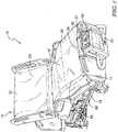
Fig. 1 is a perspective view from a foot end on the patient's right of a patient support apparatus including an air box and a patient support structure supported on a frame; -
Fig. 2 is a top plan view of the patient support apparatus ofFig. 1 where a targeted therapeutic region extends from a head section through a seat section of the patient support structure, covering an entire upper surface of the microclimate structure; -
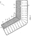
Fig. 3 is a cross section taken along section lines 3-3 ofFig. 2 showing an embodiment of the patient support structure encased by an outer ticking layer where an upper ticking covers the microclimate structure and a lower ticking encases a cushion layer; -
Fig. 4 is a perspective view of the patient support structure having a head end in an inclined position; and -
Fig. 5 is a side elevation view of the patient support structure having a head end in an inclined position. - An illustrative
patient support apparatus 10 embodied as a hospital bed is shown inFig. 1 . Thepatient support apparatus 10 includes aframe 18, apatient support structure 12 supported on theframe 18, and anair box 22. Thepatient support structure 12 is adapted to support a patient lying on thepatient support apparatus 10 and includes ahead section 32, aseat section 37, and afoot section 34. As will be discussed in further detail below, thepatient support structure 12 further includes amicroclimate structure 14 and acushion layer 16 which supports themicroclimate structure 14 as shown inFig. 3 . Thecushion layer 16 may include a plurality ofinflatable support bladders 48. Themicroclimate structure 14 is positioned on thecushion layer 16 on an occupant side and adjacent asupport surface 23 and is configured to conduct air adjacent thesupport surface 23 of thepatient support structure 12. The air conducted by themicroclimate structure 14 is pressurized and pushed through themicroclimate structure 14 by theair box 22. By conducting air along an interface of thesupport surface 23 and the patient, themicroclimate structure 14 transfers heat and moisture from the patient and cools and dries the patient's skin in order to reduce the risk of bed sore formation by the patient. - The
air box 22 further includes auser interface 60 that is configured to receive user inputs. Theuser interface 60 includes adisplay screen 21 and a plurality ofbuttons 20 for inputting patient information and for controlling operation of theair box 22 and thesupport surface 23. Particularly, theuser interface 60 allows a user to adjust the flow of air provided by theair box 22 to themicroclimate structure 14 and, in some embodiments, to adjust the temperature of air provided by theair box 22 to themicroclimate structure 14. Specifically, in some embodiments, theuser interface 60 may include a patient information input panel, an alarm panel, a lateral rotation therapy panel, an inflation mode panel, a normal inflation control panel, and a microclimate control panel. - The
microclimate structure 14 is configured to receive pressurized air from theair box 22 and to conduct air through themicroclimate structure 14 to cool and dry the interface between a patient and thepatient support apparatus 10 to promote skin health by removing patient heat and moisture along the interface when the patient is supported on thepatient support apparatus 10. Themicroclimate structure 14 generally spans laterally from aleft side 36 to aright side 38 and extends longitudinally from above alower end 86 of thehead section 32 to alower end 80 of theseat section 37, excluding thefoot section 34 of thepatient support structure 12 as shown inFig. 2 . - Referring to
Fig. 2 , in one embodiment, themicroclimate structure 14 further includes atherapeutic region 40 which is specifically configured to target specific areas of the patient's body where local climate control is most needed. This corresponds to the areas where the pressure of patient's weight against thesupport surface 23 is the greatest when the patient is lying supine and centered on themicroclimate structure 14. Thetherapeutic region 40 may be made from a highly breathable material or a perforated material. Because the patient's sweat glands are distributed non-uniformly throughout the patient's body, perspiration tends to accumulate on the skin of the patient's torso and pelvic region. Therefore, the shape of thetherapeutic region 40 is designed to provide a local climate control to those areas that are generally prone to moisture accumulation. Thetherapeutic region 40 is in thehead section 32 andseat section 37 of thepatient support structure 12 as shown inFig. 2 . The largetherapeutic region 40 ensures to underlie the patient's torso and pelvic region. By reducing the area of thetherapeutic region 40 through which theair box 22 is required to push air, themicroclimate structure 14 allows for reduction of the pressure and flow needed from an air source included in theair box 22. - The
microclimate structure 14 includes a fluid flowpath having aninlet port 42. The fluid flowpath spans laterally across themicroclimate structure 14 from itsright side 38 to itsleft side 36 and extends longitudinally through themicroclimate structure 14 to thehead section 32 of thepatient support structures 12. Theinlet port 42 is directly coupled to theair box 22 via adistribution sleeve 94 and is located at thelower end 80 of theseat section 37 of thepatient support structure 12. Thus, air from theair box 22 is introduced into themicroclimate structure 14 at the origination point orinlet port 42 near the pelvic region of the patient lying on themicroclimate structure 14. By directing the location of air introduction from theair box 22 closer to thetherapeutic region 40, themicroclimate structure 14 will provide an effective amount of cooling and drying to a patient's skin at the specific targeted areas, and achieve the effective result with minimal air. Having theinlet port 42 near thetherapeutic region 40 prevents air from diffusing out of themicroclimate structure 14 while the air flows from theinlet port 42 to thetherapeutic region 40, thus requiring less volume of air. However, in some embodiments, theinlet port 42 may be positioned at the foot end of themicroclimate structure 14. Further, themicroclimate structure 14 may have an outlet at thehead section 32 of thepatient support structure 12 to exhaust the air and/or liquid. Other inlet port and outlet designs may be used in other embodiments. When the outlet is omitted, the air that traverses themicroclimate structure 14 is pushed out through theperforations 41 in thetherapeutic region 40 and escapes through anouter ticking layer 24 of thepatient support 12. Theperforations 41 includehead section perforations 100 and seat section perforations 102. - An
outer ticking layer 24 encompasses themicroclimate structure 14 as shown inFig. 3 . Theouter ticking layer 24 includes anupper ticking layer 50 and alower ticking layer 52. Theupper ticking layer 50 covers themicroclimate structure 14 and thelower ticking layer 52 encases thecushion layer 16. Theupper ticking layer 50 includes a breathable material that is vapor permeable but liquid impermeable. This allows the patient heat and moisture to flow away from the patient's skin in form of vapor and pass through theupper ticking layer 50 into the area which encloses themicroclimate structure 14. The vapor then condenses between theupper ticking layer 50 and a first orupper layer 26 of themicroclimate structure 14. At least a portion of theupper layer 26 includes a vapor and liquid permeable material which defines thetherapeutic region 40. In the illustrative embodiment, thetherapeutic region 40 of theupper layer 26 includes a number ofperforations 41 that allows the condensed moisture and liquid from thetherapeutic region 40 to flow through theupper layer 26 into amiddle layer 28 of themicroclimate structure 14. Theupper layer 26 includes a vapor permeable but liquid impermeable material to allow vapor to flow through theupper layer 26. In the illustrated embodiments, themicroclimate structure 14 and thecushion layer 16 are separated by amiddle ticking layer 54, which is a top layer of thelower ticking layer 52. However, in some embodiments, a unitaryouter ticking layer 24 may encase the entirepatient support structure 12, including themicroclimate structure 14 and thecushion layer 16. - The material of the
middle layer 28 is a three-dimensional material. The three-dimensional material is arranged to extend from the upper end of thehead section 32 to the lower end of thefoot section 34 of thepatient support structure 12 as shown inFig. 3 . The three-dimensional material is air and liquid permeable. Theinlet port 42 is coupled to thelower end 80 of theseat section 37 of the three-dimensional material to allow air from theair box 22 to flow between theupper layer 26 and alower layer 30 of themicroclimate structure 14 and from thelower end 80 of theseat section 37 to thehead section 32 of thepatient support structure 12. Therefore, once the moisture and liquid reach themiddle layer 28 from theupper layer 26, the moisture and liquid are carried away and evaporated by air flowing through themiddle layer 28. The cooled-vapor can then be either directed toward the outlet or back toward thesupport surface 23 to cool and dry the patient's skin around the interface of the patient's skin with thesupport surface 23. The cooled-vapor directed toward thesupport surface 23 passes through thehead section perforations 100 and the seat section perforations 102. - Lastly, the
lower layer 30 of themicroclimate structure 14 includes a liquid impermeable material to prevent liquid from leaking through thelower layer 30 into thecushion layer 16. Illustratively, thecushion layer 16 includes theinflatable support bladders 48 to support themicroclimate structure 14 as shown inFig. 3 . Accordingly, theair box 22 is coupled to themicroclimate structure 14 and theinflatable support bladders 48 to provide pressurized air to thesupport surface 23 and thecushion layer 16. In other embodiments, thecushion layer 16 may omit some or all of theinflatable support bladders 48 and utilize foam cushioning structures instead of theinflatable support bladders 48. - The
patient support apparatus 10 is moveable between a declinedposition 104, shown inFigs. 2 and3 , and aninclined position 106, shown inFigs. 4 and5 . Thepatient support apparatus 10 moves between the declinedposition 104 and theinclined position 106 by altering an angle of thehead section 32 relative to theseat section 37. In the declinedposition 104, thehead section 32 extends substantially planar with theseat section 37 so that a patient may lie supine on thepatient support structure 12. In theinclined position 106, thehead section 32 is angled relative to theseat section 37 so that the patient may sit up in thepatient support structure 12, thereby applying pressure to theseat section 37. When thepatient support apparatus 10 is moved between the declinedposition 104 and theinclined position 106, thepatient support structure 12 and themicroclimate structure 14 also move between a declined and inclined position. When moved to the inclined position, theinflatable support bladders 48 may maintain an air pressure therein. Alternatively or in addition to, at least some of theinflatable support bladders 48 may deflate or inflate to accommodate the change in position of thepatient support structure 12 between the declined position and the inclined position. - In the declined
position 104, air flows from thedistribution sleeve 94 into themicroclimate structure 14 throughinlet 42. The moisture and liquid in themiddle layer 28 are carried away and evaporated by the air flowing through themiddle layer 28. The cooled-vapor can then be either directed toward the outlet or back toward thesupport surface 23 to cool and dry the patient's skin around the interface of the patient's skin with thesupport surface 23. The cooled-vapor directed toward thesupport surface 23 passes through both thehead section perforations 100 and the seat section perforations 102. - Referring to
Figs. 4 and5 , when in theinclined positon 106, acrease 108 is formed in themicroclimate structure 14. Thecrease 108 is formed between ahead section 110 of themicroclimate structure 14 and aseat section 112 of themicroclimate structure 14. Thecrease 108 spans laterally across themicroclimate structure 14 from itsright side 38 to itsleft side 36. Thecrease 108 is positioned between thehead section perforations 100 and the seat section perforations 102. Thecrease 108 extends from theupper layer 26 of themicroclimate structure 14 to thelower layer 30 of themicroclimate structure 14 through themiddle layer 28. Thecrease 108 limits the three-dimensional space within themiddle layer 28. - The
middle layer 28 may have additional material properties in the location of thecrease 108. Such additional material properties facilitate forming thecrease 108 and preventing airflow through themiddle layer 28. In some embodiments, themiddle layer 28 includes a crease material, e.g. a rubber material, a plastic material, a foam, etc., in the location where thecrease 108 is formed. Alternatively, or in addition to, themiddle layer 28 may have a higher density in the location where thecrease 108 is formed. The additional and/or thicker material facilitates forming thecrease 108 to pinch themiddle layer 28, thereby limiting the airflow through thecrease 108. In some embodiments, themiddle layer 28 has less material or a lower density at the location where thecrease 108 is formed. The reduction in material allows the ticking layer around themiddle layer 28 to fold over, thereby creating thecrease 108. - In some embodiments, the
crease 108 extends entirely from theupper layer 26 to thelower layer 28. In such an embodiment, air flow is substantially prevented from passing through thecrease 108. That is, air flow from thedistribution sleeve 94 passes frominlet 42 into theseat section 112 of themicroclimate structure 14, but is substantially prevented from entering thehead section 110 of themicroclimate structure 14. As such, the cooled-vapor formed in themiddle section 28 of themicroclimate structure 14 is directed toward thesupport surface 23 and passes through theseat section perforations 102, while being substantially prevented from passing through the head section perforations 100. - In some embodiments, the
crease 108 extends partially from theupper layer 26 to thelower layer 28. In such an embodiment, air flow is limited from passing through thecrease 108. The amount that airflow is limited may be determined by a size of thecrease 108, i.e. how far thecrease 108 extends from theupper layer 26 to thelower layer 28. Air flow from thedistribution sleeve 94 passes into aseat section 112 of themicroclimate structure 14 and is limited from entering thehead section 110 of themicroclimate structure 14, i.e. air flow into thehead section 110 is starved. As such, the cooled-vapor formed in themiddle section 28 of themicroclimate structure 14 is directed toward thesupport surface 23 and passes through theseat section perforations 102, while being limited from passing through the head section perforations 100. - Although this disclosure refers to specific embodiments, it will be understood by those skilled in the art that various changes in form and detail may be made.
Claims (17)
- A patient support apparatus comprising:a frame,an air box, anda patient support structure being supported by the frame and including a head section, a foot section, and a seat section between the head section and foot section, the patient support structure further comprising:a cushion layer,an outer ticking layer including an upper surface portion positioned to support a patient,a microclimate structure positioned within the outer ticking layer and between the cushion layer and the upper surface portion, the microclimate structure comprising an upper layer, at least a portion of the upper layer being vapor and liquid permeable, a middle layer being air permeable, and a lower layer being liquid impermeable,a first plurality of perforations extending through the upper layer of the microclimate structure in the seat section of the patient support structure, anda second plurality of perforations extending through the upper layer of the microclimate structure in the head section of the patient support structure,wherein, when the patient support structure is in a first position, the air box supplies air flow through the first plurality of perforations and the second plurality of perforations, and, when the patient support structure is in a second position, the air box supplies air flow through the first plurality of perforations and air flow through the second plurality of perforations is limited.
- The patient support apparatus of claim 1, wherein, when in the second position, a crease is formed in the microclimate structure between the first plurality of perforations and the second plurality of perforations.
- The patient support apparatus of claim 2, wherein the crease formed in the microclimate structure limits the air flow from the air box to the second plurality of perforations.
- The patient support apparatus of either claim 2 or claim 3, further comprising a crease material in the middle layer where the crease is formed.
- The patient support apparatus of claim 4, wherein the crease material comprises at least one of a rubber material, a plastic material, or a foam.
- The patient support apparatus of any one of claims 2 to 5, wherein the middle layer has a higher density or a lower density where the crease is formed.
- The patient support apparatus of any preceding claim, wherein, when in the first position, the head section is declined and/or when in the second position, the head section is inclined.
- The patient support apparatus of any preceding claim, wherein the microclimate structure extends from a lower end of the head section to a lower end of the seat section of the patient support structure, excluding the foot section of the patient support structure.
- The patient support apparatus of any preceding claim, wherein the air box is further coupled to a conduit to conduct pressurized air through the microclimate structure.
- The patient support apparatus of any preceding claim, wherein the vapor and liquid permeable portion of the upper layer of the microclimate structure defines a therapeutic region.
- The patient support apparatus of claim 10, wherein the therapeutic region of the upper layer of the microclimate structure comprises a highly breathable, vapor and liquid permeable material.
- The patient support apparatus of either claim 10 or claim 11, wherein a non-therapeutic region of the upper layer of the microclimate structure comprises a vapor permeable but liquid impermeable material.
- The patient support apparatus of any preceding claim, wherein the middle layer of the microclimate structure comprises a three-dimensional material configured to conduct air between the upper layer and the lower layer of the microclimate structure.
- The patient support apparatus of claim 13, wherein the middle layer of the microclimate structure comprises more than one section of the three dimensional material, in which at least one section of the three dimensional material conducts and delivers air along a therapeutic region.
- The patient support apparatus of any preceding claim, wherein the cushion layer includes a first inflatable support bladder and a second inflatable support bladder, and an air distribution sleeve extends between the first inflatable support bladder and the second inflatable support bladder.
- The patient support apparatus of claim 1, wherein the outer ticking layer comprises a vapor permeable and liquid impermeable material.
- The patient support apparatus of claim 1, wherein the outer ticking layer encases the microclimate structure and optionally also the cushion layer.
Applications Claiming Priority (1)
| Application Number | Priority Date | Filing Date | Title |
|---|---|---|---|
| US201762535324P | 2017-07-21 | 2017-07-21 |
Publications (2)
| Publication Number | Publication Date |
|---|---|
| EP3431066A1 true EP3431066A1 (en) | 2019-01-23 |
| EP3431066B1 EP3431066B1 (en) | 2020-12-16 |
Family
ID=62981130
Family Applications (1)
| Application Number | Title | Priority Date | Filing Date |
|---|---|---|---|
| EP18184040.6A Active EP3431066B1 (en) | 2017-07-21 | 2018-07-17 | Patient cooling system responsive to head elevation |
Country Status (4)
| Country | Link |
|---|---|
| US (1) | US20190021926A1 (en) |
| EP (1) | EP3431066B1 (en) |
| JP (1) | JP6680835B2 (en) |
| CN (1) | CN109276385B (en) |
Families Citing this family (2)
| Publication number | Priority date | Publication date | Assignee | Title |
|---|---|---|---|---|
| US20200253387A1 (en) * | 2019-02-08 | 2020-08-13 | Hill-Rom Services, Inc. | Method for optimizing skin cooling level of an occupant support surface |
| JP7017593B2 (en) * | 2020-03-04 | 2022-02-08 | 京華堂實業股▲ふん▼有限公司 | Nursing bed |
Citations (1)
| Publication number | Priority date | Publication date | Assignee | Title |
|---|---|---|---|---|
| US9226863B1 (en) * | 2015-03-30 | 2016-01-05 | King Saud University | Mattress for relieving pressure ulcers |
Family Cites Families (9)
| Publication number | Priority date | Publication date | Assignee | Title |
|---|---|---|---|---|
| US7685658B2 (en) * | 2004-04-30 | 2010-03-30 | Nitta Corporation | Body support apparatus having automatic pressure control and related methods |
| US7914611B2 (en) * | 2006-05-11 | 2011-03-29 | Kci Licensing, Inc. | Multi-layered support system |
| FR2907646B1 (en) * | 2006-10-26 | 2009-02-06 | Hill Rom Ind S A Sa | DEVICE AND METHOD FOR CONTROLLING MOISTURE AT THE SURFACE OF A MATTRESS TYPE SUPPORT ELEMENT. |
| JP4273358B2 (en) * | 2007-05-09 | 2009-06-03 | 株式会社オムニ商会 | Bedsore prevention mattress |
| KR20110086859A (en) * | 2008-11-19 | 2011-08-01 | 케이씨아이 라이센싱 인코포레이티드 | Multi-layered support system and method thereof |
| US8332975B2 (en) * | 2009-08-31 | 2012-12-18 | Gentherm Incorporated | Climate-controlled topper member for medical beds |
| US9538853B2 (en) * | 2010-05-27 | 2017-01-10 | Huntleigh Technology Limited | Multi-layer support system |
| US9433300B2 (en) * | 2013-02-28 | 2016-09-06 | Hill-Rom Services, Inc. | Topper for a patient surface |
| CN204337192U (en) * | 2014-12-19 | 2015-05-20 | 王国运 | Counteracting bedsores mattress |
-
2018
- 2018-07-05 US US16/027,533 patent/US20190021926A1/en not_active Abandoned
- 2018-07-13 JP JP2018133455A patent/JP6680835B2/en active Active
- 2018-07-17 EP EP18184040.6A patent/EP3431066B1/en active Active
- 2018-07-20 CN CN201810806708.4A patent/CN109276385B/en active Active
Patent Citations (1)
| Publication number | Priority date | Publication date | Assignee | Title |
|---|---|---|---|---|
| US9226863B1 (en) * | 2015-03-30 | 2016-01-05 | King Saud University | Mattress for relieving pressure ulcers |
Also Published As
| Publication number | Publication date |
|---|---|
| CN109276385B (en) | 2021-01-15 |
| EP3431066B1 (en) | 2020-12-16 |
| US20190021926A1 (en) | 2019-01-24 |
| JP6680835B2 (en) | 2020-04-15 |
| CN109276385A (en) | 2019-01-29 |
| JP2019048037A (en) | 2019-03-28 |
Similar Documents
| Publication | Publication Date | Title |
|---|---|---|
| US10426681B2 (en) | Topper for a patient surface with flexible fabric sleeves | |
| US7712171B2 (en) | Patient support including turn assist, low air loss, or integrated lateral transfer | |
| US7469436B2 (en) | Pressure relief surface | |
| US7469432B2 (en) | Method and apparatus for improving air flow under a patient | |
| US10265231B2 (en) | Self-powered microclimate controlled mattress | |
| US20140007353A1 (en) | Patient turner | |
| US20160213539A1 (en) | Sensors in a mattress cover | |
| US20110010855A1 (en) | Therapy and Low Air Loss Universal Coverlet | |
| US20200268163A1 (en) | Mattress with valve system | |
| EP3431066B1 (en) | Patient cooling system responsive to head elevation | |
| EP3964187B1 (en) | Hospital bed with inflatable bladders and cooling channels and related methods | |
| KR100904625B1 (en) | Dry device of mattress for preventing bedsore | |
| EP2520200B1 (en) | Temperature and moistrure regulating topper for non-powered person-support surfaces |
Legal Events
| Date | Code | Title | Description |
|---|---|---|---|
| PUAI | Public reference made under article 153(3) epc to a published international application that has entered the european phase |
Free format text: ORIGINAL CODE: 0009012 |
|
| STAA | Information on the status of an ep patent application or granted ep patent |
Free format text: STATUS: THE APPLICATION HAS BEEN PUBLISHED |
|
| AK | Designated contracting states |
Kind code of ref document: A1 Designated state(s): AL AT BE BG CH CY CZ DE DK EE ES FI FR GB GR HR HU IE IS IT LI LT LU LV MC MK MT NL NO PL PT RO RS SE SI SK SM TR |
|
| AX | Request for extension of the european patent |
Extension state: BA ME |
|
| STAA | Information on the status of an ep patent application or granted ep patent |
Free format text: STATUS: REQUEST FOR EXAMINATION WAS MADE |
|
| 17P | Request for examination filed |
Effective date: 20190722 |
|
| RBV | Designated contracting states (corrected) |
Designated state(s): AL AT BE BG CH CY CZ DE DK EE ES FI FR GB GR HR HU IE IS IT LI LT LU LV MC MK MT NL NO PL PT RO RS SE SI SK SM TR |
|
| STAA | Information on the status of an ep patent application or granted ep patent |
Free format text: STATUS: EXAMINATION IS IN PROGRESS |
|
| 17Q | First examination report despatched |
Effective date: 20191126 |
|
| GRAP | Despatch of communication of intention to grant a patent |
Free format text: ORIGINAL CODE: EPIDOSNIGR1 |
|
| STAA | Information on the status of an ep patent application or granted ep patent |
Free format text: STATUS: GRANT OF PATENT IS INTENDED |
|
| RIC1 | Information provided on ipc code assigned before grant |
Ipc: A61G 7/057 20060101AFI20200619BHEP Ipc: A61G 7/07 20060101ALN20200619BHEP Ipc: A61G 7/015 20060101ALN20200619BHEP |
|
| INTG | Intention to grant announced |
Effective date: 20200713 |
|
| GRAS | Grant fee paid |
Free format text: ORIGINAL CODE: EPIDOSNIGR3 |
|
| GRAA | (expected) grant |
Free format text: ORIGINAL CODE: 0009210 |
|
| STAA | Information on the status of an ep patent application or granted ep patent |
Free format text: STATUS: THE PATENT HAS BEEN GRANTED |
|
| AK | Designated contracting states |
Kind code of ref document: B1 Designated state(s): AL AT BE BG CH CY CZ DE DK EE ES FI FR GB GR HR HU IE IS IT LI LT LU LV MC MK MT NL NO PL PT RO RS SE SI SK SM TR |
|
| REG | Reference to a national code |
Ref country code: GB Ref legal event code: FG4D |
|
| REG | Reference to a national code |
Ref country code: DE Ref legal event code: R096 Ref document number: 602018010787 Country of ref document: DE |
|
| REG | Reference to a national code |
Ref country code: IE Ref legal event code: FG4D |
|
| REG | Reference to a national code |
Ref country code: AT Ref legal event code: REF Ref document number: 1344915 Country of ref document: AT Kind code of ref document: T Effective date: 20210115 |
|
| PG25 | Lapsed in a contracting state [announced via postgrant information from national office to epo] |
Ref country code: GR Free format text: LAPSE BECAUSE OF FAILURE TO SUBMIT A TRANSLATION OF THE DESCRIPTION OR TO PAY THE FEE WITHIN THE PRESCRIBED TIME-LIMIT Effective date: 20210317 Ref country code: NO Free format text: LAPSE BECAUSE OF FAILURE TO SUBMIT A TRANSLATION OF THE DESCRIPTION OR TO PAY THE FEE WITHIN THE PRESCRIBED TIME-LIMIT Effective date: 20210316 Ref country code: RS Free format text: LAPSE BECAUSE OF FAILURE TO SUBMIT A TRANSLATION OF THE DESCRIPTION OR TO PAY THE FEE WITHIN THE PRESCRIBED TIME-LIMIT Effective date: 20201216 Ref country code: FI Free format text: LAPSE BECAUSE OF FAILURE TO SUBMIT A TRANSLATION OF THE DESCRIPTION OR TO PAY THE FEE WITHIN THE PRESCRIBED TIME-LIMIT Effective date: 20201216 |
|
| REG | Reference to a national code |
Ref country code: AT Ref legal event code: MK05 Ref document number: 1344915 Country of ref document: AT Kind code of ref document: T Effective date: 20201216 |
|
| REG | Reference to a national code |
Ref country code: NL Ref legal event code: MP Effective date: 20201216 |
|
| PG25 | Lapsed in a contracting state [announced via postgrant information from national office to epo] |
Ref country code: BG Free format text: LAPSE BECAUSE OF FAILURE TO SUBMIT A TRANSLATION OF THE DESCRIPTION OR TO PAY THE FEE WITHIN THE PRESCRIBED TIME-LIMIT Effective date: 20210316 Ref country code: SE Free format text: LAPSE BECAUSE OF FAILURE TO SUBMIT A TRANSLATION OF THE DESCRIPTION OR TO PAY THE FEE WITHIN THE PRESCRIBED TIME-LIMIT Effective date: 20201216 Ref country code: LV Free format text: LAPSE BECAUSE OF FAILURE TO SUBMIT A TRANSLATION OF THE DESCRIPTION OR TO PAY THE FEE WITHIN THE PRESCRIBED TIME-LIMIT Effective date: 20201216 |
|
| PG25 | Lapsed in a contracting state [announced via postgrant information from national office to epo] |
Ref country code: HR Free format text: LAPSE BECAUSE OF FAILURE TO SUBMIT A TRANSLATION OF THE DESCRIPTION OR TO PAY THE FEE WITHIN THE PRESCRIBED TIME-LIMIT Effective date: 20201216 Ref country code: NL Free format text: LAPSE BECAUSE OF FAILURE TO SUBMIT A TRANSLATION OF THE DESCRIPTION OR TO PAY THE FEE WITHIN THE PRESCRIBED TIME-LIMIT Effective date: 20201216 |
|
| REG | Reference to a national code |
Ref country code: LT Ref legal event code: MG9D |
|
| PG25 | Lapsed in a contracting state [announced via postgrant information from national office to epo] |
Ref country code: SM Free format text: LAPSE BECAUSE OF FAILURE TO SUBMIT A TRANSLATION OF THE DESCRIPTION OR TO PAY THE FEE WITHIN THE PRESCRIBED TIME-LIMIT Effective date: 20201216 Ref country code: CZ Free format text: LAPSE BECAUSE OF FAILURE TO SUBMIT A TRANSLATION OF THE DESCRIPTION OR TO PAY THE FEE WITHIN THE PRESCRIBED TIME-LIMIT Effective date: 20201216 Ref country code: EE Free format text: LAPSE BECAUSE OF FAILURE TO SUBMIT A TRANSLATION OF THE DESCRIPTION OR TO PAY THE FEE WITHIN THE PRESCRIBED TIME-LIMIT Effective date: 20201216 Ref country code: LT Free format text: LAPSE BECAUSE OF FAILURE TO SUBMIT A TRANSLATION OF THE DESCRIPTION OR TO PAY THE FEE WITHIN THE PRESCRIBED TIME-LIMIT Effective date: 20201216 Ref country code: SK Free format text: LAPSE BECAUSE OF FAILURE TO SUBMIT A TRANSLATION OF THE DESCRIPTION OR TO PAY THE FEE WITHIN THE PRESCRIBED TIME-LIMIT Effective date: 20201216 Ref country code: RO Free format text: LAPSE BECAUSE OF FAILURE TO SUBMIT A TRANSLATION OF THE DESCRIPTION OR TO PAY THE FEE WITHIN THE PRESCRIBED TIME-LIMIT Effective date: 20201216 Ref country code: PT Free format text: LAPSE BECAUSE OF FAILURE TO SUBMIT A TRANSLATION OF THE DESCRIPTION OR TO PAY THE FEE WITHIN THE PRESCRIBED TIME-LIMIT Effective date: 20210416 |
|
| PG25 | Lapsed in a contracting state [announced via postgrant information from national office to epo] |
Ref country code: PL Free format text: LAPSE BECAUSE OF FAILURE TO SUBMIT A TRANSLATION OF THE DESCRIPTION OR TO PAY THE FEE WITHIN THE PRESCRIBED TIME-LIMIT Effective date: 20201216 Ref country code: AT Free format text: LAPSE BECAUSE OF FAILURE TO SUBMIT A TRANSLATION OF THE DESCRIPTION OR TO PAY THE FEE WITHIN THE PRESCRIBED TIME-LIMIT Effective date: 20201216 |
|
| REG | Reference to a national code |
Ref country code: DE Ref legal event code: R097 Ref document number: 602018010787 Country of ref document: DE |
|
| PG25 | Lapsed in a contracting state [announced via postgrant information from national office to epo] |
Ref country code: IS Free format text: LAPSE BECAUSE OF FAILURE TO SUBMIT A TRANSLATION OF THE DESCRIPTION OR TO PAY THE FEE WITHIN THE PRESCRIBED TIME-LIMIT Effective date: 20210416 |
|
| PLBE | No opposition filed within time limit |
Free format text: ORIGINAL CODE: 0009261 |
|
| STAA | Information on the status of an ep patent application or granted ep patent |
Free format text: STATUS: NO OPPOSITION FILED WITHIN TIME LIMIT |
|
| PG25 | Lapsed in a contracting state [announced via postgrant information from national office to epo] |
Ref country code: AL Free format text: LAPSE BECAUSE OF FAILURE TO SUBMIT A TRANSLATION OF THE DESCRIPTION OR TO PAY THE FEE WITHIN THE PRESCRIBED TIME-LIMIT Effective date: 20201216 Ref country code: IT Free format text: LAPSE BECAUSE OF FAILURE TO SUBMIT A TRANSLATION OF THE DESCRIPTION OR TO PAY THE FEE WITHIN THE PRESCRIBED TIME-LIMIT Effective date: 20201216 |
|
| 26N | No opposition filed |
Effective date: 20210917 |
|
| PG25 | Lapsed in a contracting state [announced via postgrant information from national office to epo] |
Ref country code: DK Free format text: LAPSE BECAUSE OF FAILURE TO SUBMIT A TRANSLATION OF THE DESCRIPTION OR TO PAY THE FEE WITHIN THE PRESCRIBED TIME-LIMIT Effective date: 20201216 |
|
| PG25 | Lapsed in a contracting state [announced via postgrant information from national office to epo] |
Ref country code: ES Free format text: LAPSE BECAUSE OF FAILURE TO SUBMIT A TRANSLATION OF THE DESCRIPTION OR TO PAY THE FEE WITHIN THE PRESCRIBED TIME-LIMIT Effective date: 20201216 |
|
| PG25 | Lapsed in a contracting state [announced via postgrant information from national office to epo] |
Ref country code: SI Free format text: LAPSE BECAUSE OF FAILURE TO SUBMIT A TRANSLATION OF THE DESCRIPTION OR TO PAY THE FEE WITHIN THE PRESCRIBED TIME-LIMIT Effective date: 20201216 |
|
| REG | Reference to a national code |
Ref country code: CH Ref legal event code: PL |
|
| PG25 | Lapsed in a contracting state [announced via postgrant information from national office to epo] |
Ref country code: MC Free format text: LAPSE BECAUSE OF FAILURE TO SUBMIT A TRANSLATION OF THE DESCRIPTION OR TO PAY THE FEE WITHIN THE PRESCRIBED TIME-LIMIT Effective date: 20201216 |
|
| REG | Reference to a national code |
Ref country code: BE Ref legal event code: MM Effective date: 20210731 |
|
| PG25 | Lapsed in a contracting state [announced via postgrant information from national office to epo] |
Ref country code: LI Free format text: LAPSE BECAUSE OF NON-PAYMENT OF DUE FEES Effective date: 20210731 Ref country code: CH Free format text: LAPSE BECAUSE OF NON-PAYMENT OF DUE FEES Effective date: 20210731 |
|
| PG25 | Lapsed in a contracting state [announced via postgrant information from national office to epo] |
Ref country code: IS Free format text: LAPSE BECAUSE OF FAILURE TO SUBMIT A TRANSLATION OF THE DESCRIPTION OR TO PAY THE FEE WITHIN THE PRESCRIBED TIME-LIMIT Effective date: 20210416 Ref country code: LU Free format text: LAPSE BECAUSE OF NON-PAYMENT OF DUE FEES Effective date: 20210717 |
|
| PG25 | Lapsed in a contracting state [announced via postgrant information from national office to epo] |
Ref country code: IE Free format text: LAPSE BECAUSE OF NON-PAYMENT OF DUE FEES Effective date: 20210717 Ref country code: BE Free format text: LAPSE BECAUSE OF NON-PAYMENT OF DUE FEES Effective date: 20210731 |
|
| PG25 | Lapsed in a contracting state [announced via postgrant information from national office to epo] |
Ref country code: CY Free format text: LAPSE BECAUSE OF FAILURE TO SUBMIT A TRANSLATION OF THE DESCRIPTION OR TO PAY THE FEE WITHIN THE PRESCRIBED TIME-LIMIT Effective date: 20201216 |
|
| PG25 | Lapsed in a contracting state [announced via postgrant information from national office to epo] |
Ref country code: HU Free format text: LAPSE BECAUSE OF FAILURE TO SUBMIT A TRANSLATION OF THE DESCRIPTION OR TO PAY THE FEE WITHIN THE PRESCRIBED TIME-LIMIT; INVALID AB INITIO Effective date: 20180717 |
|
| PGFP | Annual fee paid to national office [announced via postgrant information from national office to epo] |
Ref country code: FR Payment date: 20230621 Year of fee payment: 6 |
|
| PGFP | Annual fee paid to national office [announced via postgrant information from national office to epo] |
Ref country code: GB Payment date: 20230620 Year of fee payment: 6 |
|
| PGFP | Annual fee paid to national office [announced via postgrant information from national office to epo] |
Ref country code: DE Payment date: 20230620 Year of fee payment: 6 |