EP3431049A1 - Stent - Google Patents
Stent Download PDFInfo
- Publication number
- EP3431049A1 EP3431049A1 EP16894602.8A EP16894602A EP3431049A1 EP 3431049 A1 EP3431049 A1 EP 3431049A1 EP 16894602 A EP16894602 A EP 16894602A EP 3431049 A1 EP3431049 A1 EP 3431049A1
- Authority
- EP
- European Patent Office
- Prior art keywords
- upstream
- convex portion
- stent
- downstream
- axial direction
- Prior art date
- Legal status (The legal status is an assumption and is not a legal conclusion. Google has not performed a legal analysis and makes no representation as to the accuracy of the status listed.)
- Withdrawn
Links
- 238000011144 upstream manufacturing Methods 0.000 claims abstract description 116
- 230000017531 blood circulation Effects 0.000 claims abstract description 65
- 238000001746 injection moulding Methods 0.000 claims description 4
- 238000000465 moulding Methods 0.000 claims description 2
- 208000007536 Thrombosis Diseases 0.000 abstract description 23
- 230000015572 biosynthetic process Effects 0.000 abstract description 22
- 210000004204 blood vessel Anatomy 0.000 description 32
- 239000008280 blood Substances 0.000 description 18
- 210000004369 blood Anatomy 0.000 description 18
- 239000000463 material Substances 0.000 description 11
- 238000000926 separation method Methods 0.000 description 11
- 239000003814 drug Substances 0.000 description 7
- 230000000052 comparative effect Effects 0.000 description 6
- 238000000034 method Methods 0.000 description 6
- 230000004048 modification Effects 0.000 description 6
- 238000012986 modification Methods 0.000 description 6
- 239000011248 coating agent Substances 0.000 description 5
- 238000000576 coating method Methods 0.000 description 5
- 229910045601 alloy Inorganic materials 0.000 description 3
- 239000000956 alloy Substances 0.000 description 3
- 229920001577 copolymer Polymers 0.000 description 3
- 230000000694 effects Effects 0.000 description 3
- 238000010030 laminating Methods 0.000 description 2
- 238000004519 manufacturing process Methods 0.000 description 2
- 229910000531 Co alloy Inorganic materials 0.000 description 1
- 102000008186 Collagen Human genes 0.000 description 1
- 108010035532 Collagen Proteins 0.000 description 1
- 229910000599 Cr alloy Inorganic materials 0.000 description 1
- HKVAMNSJSFKALM-GKUWKFKPSA-N Everolimus Chemical compound C1C[C@@H](OCCO)[C@H](OC)C[C@@H]1C[C@@H](C)[C@H]1OC(=O)[C@@H]2CCCCN2C(=O)C(=O)[C@](O)(O2)[C@H](C)CC[C@H]2C[C@H](OC)/C(C)=C/C=C/C=C/[C@@H](C)C[C@@H](C)C(=O)[C@H](OC)[C@H](O)/C(C)=C/[C@@H](C)C(=O)C1 HKVAMNSJSFKALM-GKUWKFKPSA-N 0.000 description 1
- FYYHWMGAXLPEAU-UHFFFAOYSA-N Magnesium Chemical compound [Mg] FYYHWMGAXLPEAU-UHFFFAOYSA-N 0.000 description 1
- 208000034827 Neointima Diseases 0.000 description 1
- 229930012538 Paclitaxel Natural products 0.000 description 1
- 229920000954 Polyglycolide Polymers 0.000 description 1
- HCHKCACWOHOZIP-UHFFFAOYSA-N Zinc Chemical compound [Zn] HCHKCACWOHOZIP-UHFFFAOYSA-N 0.000 description 1
- WAIPAZQMEIHHTJ-UHFFFAOYSA-N [Cr].[Co] Chemical class [Cr].[Co] WAIPAZQMEIHHTJ-UHFFFAOYSA-N 0.000 description 1
- 239000000788 chromium alloy Substances 0.000 description 1
- MMAADVOQRITKKL-UHFFFAOYSA-N chromium platinum Chemical compound [Cr].[Pt] MMAADVOQRITKKL-UHFFFAOYSA-N 0.000 description 1
- 229920001436 collagen Polymers 0.000 description 1
- 239000000470 constituent Substances 0.000 description 1
- 229960005167 everolimus Drugs 0.000 description 1
- 239000012530 fluid Substances 0.000 description 1
- 239000004220 glutamic acid Substances 0.000 description 1
- 238000001727 in vivo Methods 0.000 description 1
- 229910052749 magnesium Inorganic materials 0.000 description 1
- 239000011777 magnesium Substances 0.000 description 1
- 229910052751 metal Inorganic materials 0.000 description 1
- 239000002184 metal Substances 0.000 description 1
- 239000007769 metal material Substances 0.000 description 1
- 229920005615 natural polymer Polymers 0.000 description 1
- 229910001000 nickel titanium Inorganic materials 0.000 description 1
- 229960001592 paclitaxel Drugs 0.000 description 1
- 229920000747 poly(lactic acid) Polymers 0.000 description 1
- 229920001610 polycaprolactone Polymers 0.000 description 1
- 239000004632 polycaprolactone Substances 0.000 description 1
- 239000004633 polyglycolic acid Substances 0.000 description 1
- 239000004626 polylactic acid Substances 0.000 description 1
- 239000002861 polymer material Substances 0.000 description 1
- 230000035755 proliferation Effects 0.000 description 1
- ZAHRKKWIAAJSAO-UHFFFAOYSA-N rapamycin Natural products COCC(O)C(=C/C(C)C(=O)CC(OC(=O)C1CCCCN1C(=O)C(=O)C2(O)OC(CC(OC)C(=CC=CC=CC(C)CC(C)C(=O)C)C)CCC2C)C(C)CC3CCC(O)C(C3)OC)C ZAHRKKWIAAJSAO-UHFFFAOYSA-N 0.000 description 1
- 238000004088 simulation Methods 0.000 description 1
- QFJCIRLUMZQUOT-HPLJOQBZSA-N sirolimus Chemical compound C1C[C@@H](O)[C@H](OC)C[C@@H]1C[C@@H](C)[C@H]1OC(=O)[C@@H]2CCCCN2C(=O)C(=O)[C@](O)(O2)[C@H](C)CC[C@H]2C[C@H](OC)/C(C)=C/C=C/C=C/[C@@H](C)C[C@@H](C)C(=O)[C@H](OC)[C@H](O)/C(C)=C/[C@@H](C)C(=O)C1 QFJCIRLUMZQUOT-HPLJOQBZSA-N 0.000 description 1
- 229960002930 sirolimus Drugs 0.000 description 1
- 239000000243 solution Substances 0.000 description 1
- 239000010935 stainless steel Substances 0.000 description 1
- 229910001220 stainless steel Inorganic materials 0.000 description 1
- RCINICONZNJXQF-MZXODVADSA-N taxol Chemical compound O([C@@H]1[C@@]2(C[C@@H](C(C)=C(C2(C)C)[C@H](C([C@]2(C)[C@@H](O)C[C@H]3OC[C@]3([C@H]21)OC(C)=O)=O)OC(=O)C)OC(=O)[C@H](O)[C@@H](NC(=O)C=1C=CC=CC=1)C=1C=CC=CC=1)O)C(=O)C1=CC=CC=C1 RCINICONZNJXQF-MZXODVADSA-N 0.000 description 1
- 229910052725 zinc Inorganic materials 0.000 description 1
- 239000011701 zinc Substances 0.000 description 1
- CGTADGCBEXYWNE-JUKNQOCSSA-N zotarolimus Chemical compound N1([C@H]2CC[C@@H](C[C@@H](C)[C@H]3OC(=O)[C@@H]4CCCCN4C(=O)C(=O)[C@@]4(O)[C@H](C)CC[C@H](O4)C[C@@H](/C(C)=C/C=C/C=C/[C@@H](C)C[C@@H](C)C(=O)[C@H](OC)[C@H](O)/C(C)=C/[C@@H](C)C(=O)C3)OC)C[C@H]2OC)C=NN=N1 CGTADGCBEXYWNE-JUKNQOCSSA-N 0.000 description 1
- 229950009819 zotarolimus Drugs 0.000 description 1
Images




Classifications
-
- A—HUMAN NECESSITIES
- A61—MEDICAL OR VETERINARY SCIENCE; HYGIENE
- A61F—FILTERS IMPLANTABLE INTO BLOOD VESSELS; PROSTHESES; DEVICES PROVIDING PATENCY TO, OR PREVENTING COLLAPSING OF, TUBULAR STRUCTURES OF THE BODY, e.g. STENTS; ORTHOPAEDIC, NURSING OR CONTRACEPTIVE DEVICES; FOMENTATION; TREATMENT OR PROTECTION OF EYES OR EARS; BANDAGES, DRESSINGS OR ABSORBENT PADS; FIRST-AID KITS
- A61F2/00—Filters implantable into blood vessels; Prostheses, i.e. artificial substitutes or replacements for parts of the body; Appliances for connecting them with the body; Devices providing patency to, or preventing collapsing of, tubular structures of the body, e.g. stents
- A61F2/82—Devices providing patency to, or preventing collapsing of, tubular structures of the body, e.g. stents
- A61F2/86—Stents in a form characterised by the wire-like elements; Stents in the form characterised by a net-like or mesh-like structure
- A61F2/90—Stents in a form characterised by the wire-like elements; Stents in the form characterised by a net-like or mesh-like structure characterised by a net-like or mesh-like structure
- A61F2/91—Stents in a form characterised by the wire-like elements; Stents in the form characterised by a net-like or mesh-like structure characterised by a net-like or mesh-like structure made from perforated sheets or tubes, e.g. perforated by laser cuts or etched holes
- A61F2/915—Stents in a form characterised by the wire-like elements; Stents in the form characterised by a net-like or mesh-like structure characterised by a net-like or mesh-like structure made from perforated sheets or tubes, e.g. perforated by laser cuts or etched holes with bands having a meander structure, adjacent bands being connected to each other
-
- A—HUMAN NECESSITIES
- A61—MEDICAL OR VETERINARY SCIENCE; HYGIENE
- A61F—FILTERS IMPLANTABLE INTO BLOOD VESSELS; PROSTHESES; DEVICES PROVIDING PATENCY TO, OR PREVENTING COLLAPSING OF, TUBULAR STRUCTURES OF THE BODY, e.g. STENTS; ORTHOPAEDIC, NURSING OR CONTRACEPTIVE DEVICES; FOMENTATION; TREATMENT OR PROTECTION OF EYES OR EARS; BANDAGES, DRESSINGS OR ABSORBENT PADS; FIRST-AID KITS
- A61F2/00—Filters implantable into blood vessels; Prostheses, i.e. artificial substitutes or replacements for parts of the body; Appliances for connecting them with the body; Devices providing patency to, or preventing collapsing of, tubular structures of the body, e.g. stents
- A61F2/82—Devices providing patency to, or preventing collapsing of, tubular structures of the body, e.g. stents
- A61F2/86—Stents in a form characterised by the wire-like elements; Stents in the form characterised by a net-like or mesh-like structure
- A61F2/90—Stents in a form characterised by the wire-like elements; Stents in the form characterised by a net-like or mesh-like structure characterised by a net-like or mesh-like structure
-
- A—HUMAN NECESSITIES
- A61—MEDICAL OR VETERINARY SCIENCE; HYGIENE
- A61F—FILTERS IMPLANTABLE INTO BLOOD VESSELS; PROSTHESES; DEVICES PROVIDING PATENCY TO, OR PREVENTING COLLAPSING OF, TUBULAR STRUCTURES OF THE BODY, e.g. STENTS; ORTHOPAEDIC, NURSING OR CONTRACEPTIVE DEVICES; FOMENTATION; TREATMENT OR PROTECTION OF EYES OR EARS; BANDAGES, DRESSINGS OR ABSORBENT PADS; FIRST-AID KITS
- A61F2/00—Filters implantable into blood vessels; Prostheses, i.e. artificial substitutes or replacements for parts of the body; Appliances for connecting them with the body; Devices providing patency to, or preventing collapsing of, tubular structures of the body, e.g. stents
- A61F2/82—Devices providing patency to, or preventing collapsing of, tubular structures of the body, e.g. stents
-
- A—HUMAN NECESSITIES
- A61—MEDICAL OR VETERINARY SCIENCE; HYGIENE
- A61F—FILTERS IMPLANTABLE INTO BLOOD VESSELS; PROSTHESES; DEVICES PROVIDING PATENCY TO, OR PREVENTING COLLAPSING OF, TUBULAR STRUCTURES OF THE BODY, e.g. STENTS; ORTHOPAEDIC, NURSING OR CONTRACEPTIVE DEVICES; FOMENTATION; TREATMENT OR PROTECTION OF EYES OR EARS; BANDAGES, DRESSINGS OR ABSORBENT PADS; FIRST-AID KITS
- A61F2/00—Filters implantable into blood vessels; Prostheses, i.e. artificial substitutes or replacements for parts of the body; Appliances for connecting them with the body; Devices providing patency to, or preventing collapsing of, tubular structures of the body, e.g. stents
- A61F2/02—Prostheses implantable into the body
- A61F2/04—Hollow or tubular parts of organs, e.g. bladders, tracheae, bronchi or bile ducts
- A61F2/06—Blood vessels
- A61F2002/068—Modifying the blood flow model, e.g. by diffuser or deflector
-
- A—HUMAN NECESSITIES
- A61—MEDICAL OR VETERINARY SCIENCE; HYGIENE
- A61F—FILTERS IMPLANTABLE INTO BLOOD VESSELS; PROSTHESES; DEVICES PROVIDING PATENCY TO, OR PREVENTING COLLAPSING OF, TUBULAR STRUCTURES OF THE BODY, e.g. STENTS; ORTHOPAEDIC, NURSING OR CONTRACEPTIVE DEVICES; FOMENTATION; TREATMENT OR PROTECTION OF EYES OR EARS; BANDAGES, DRESSINGS OR ABSORBENT PADS; FIRST-AID KITS
- A61F2/00—Filters implantable into blood vessels; Prostheses, i.e. artificial substitutes or replacements for parts of the body; Appliances for connecting them with the body; Devices providing patency to, or preventing collapsing of, tubular structures of the body, e.g. stents
- A61F2/82—Devices providing patency to, or preventing collapsing of, tubular structures of the body, e.g. stents
- A61F2/86—Stents in a form characterised by the wire-like elements; Stents in the form characterised by a net-like or mesh-like structure
- A61F2/90—Stents in a form characterised by the wire-like elements; Stents in the form characterised by a net-like or mesh-like structure characterised by a net-like or mesh-like structure
- A61F2/91—Stents in a form characterised by the wire-like elements; Stents in the form characterised by a net-like or mesh-like structure characterised by a net-like or mesh-like structure made from perforated sheets or tubes, e.g. perforated by laser cuts or etched holes
- A61F2/915—Stents in a form characterised by the wire-like elements; Stents in the form characterised by a net-like or mesh-like structure characterised by a net-like or mesh-like structure made from perforated sheets or tubes, e.g. perforated by laser cuts or etched holes with bands having a meander structure, adjacent bands being connected to each other
- A61F2002/9155—Adjacent bands being connected to each other
- A61F2002/91575—Adjacent bands being connected to each other connected peak to trough
-
- A—HUMAN NECESSITIES
- A61—MEDICAL OR VETERINARY SCIENCE; HYGIENE
- A61F—FILTERS IMPLANTABLE INTO BLOOD VESSELS; PROSTHESES; DEVICES PROVIDING PATENCY TO, OR PREVENTING COLLAPSING OF, TUBULAR STRUCTURES OF THE BODY, e.g. STENTS; ORTHOPAEDIC, NURSING OR CONTRACEPTIVE DEVICES; FOMENTATION; TREATMENT OR PROTECTION OF EYES OR EARS; BANDAGES, DRESSINGS OR ABSORBENT PADS; FIRST-AID KITS
- A61F2220/00—Fixations or connections for prostheses classified in groups A61F2/00 - A61F2/26 or A61F2/82 or A61F9/00 or A61F11/00 or subgroups thereof
- A61F2220/0025—Connections or couplings between prosthetic parts, e.g. between modular parts; Connecting elements
-
- A—HUMAN NECESSITIES
- A61—MEDICAL OR VETERINARY SCIENCE; HYGIENE
- A61F—FILTERS IMPLANTABLE INTO BLOOD VESSELS; PROSTHESES; DEVICES PROVIDING PATENCY TO, OR PREVENTING COLLAPSING OF, TUBULAR STRUCTURES OF THE BODY, e.g. STENTS; ORTHOPAEDIC, NURSING OR CONTRACEPTIVE DEVICES; FOMENTATION; TREATMENT OR PROTECTION OF EYES OR EARS; BANDAGES, DRESSINGS OR ABSORBENT PADS; FIRST-AID KITS
- A61F2230/00—Geometry of prostheses classified in groups A61F2/00 - A61F2/26 or A61F2/82 or A61F9/00 or A61F11/00 or subgroups thereof
- A61F2230/0002—Two-dimensional shapes, e.g. cross-sections
- A61F2230/0017—Angular shapes
- A61F2230/0023—Angular shapes triangular
-
- A—HUMAN NECESSITIES
- A61—MEDICAL OR VETERINARY SCIENCE; HYGIENE
- A61F—FILTERS IMPLANTABLE INTO BLOOD VESSELS; PROSTHESES; DEVICES PROVIDING PATENCY TO, OR PREVENTING COLLAPSING OF, TUBULAR STRUCTURES OF THE BODY, e.g. STENTS; ORTHOPAEDIC, NURSING OR CONTRACEPTIVE DEVICES; FOMENTATION; TREATMENT OR PROTECTION OF EYES OR EARS; BANDAGES, DRESSINGS OR ABSORBENT PADS; FIRST-AID KITS
- A61F2230/00—Geometry of prostheses classified in groups A61F2/00 - A61F2/26 or A61F2/82 or A61F9/00 or A61F11/00 or subgroups thereof
- A61F2230/0063—Three-dimensional shapes
- A61F2230/0069—Three-dimensional shapes cylindrical
-
- A—HUMAN NECESSITIES
- A61—MEDICAL OR VETERINARY SCIENCE; HYGIENE
- A61F—FILTERS IMPLANTABLE INTO BLOOD VESSELS; PROSTHESES; DEVICES PROVIDING PATENCY TO, OR PREVENTING COLLAPSING OF, TUBULAR STRUCTURES OF THE BODY, e.g. STENTS; ORTHOPAEDIC, NURSING OR CONTRACEPTIVE DEVICES; FOMENTATION; TREATMENT OR PROTECTION OF EYES OR EARS; BANDAGES, DRESSINGS OR ABSORBENT PADS; FIRST-AID KITS
- A61F2240/00—Manufacturing or designing of prostheses classified in groups A61F2/00 - A61F2/26 or A61F2/82 or A61F9/00 or A61F11/00 or subgroups thereof
- A61F2240/001—Designing or manufacturing processes
-
- A—HUMAN NECESSITIES
- A61—MEDICAL OR VETERINARY SCIENCE; HYGIENE
- A61F—FILTERS IMPLANTABLE INTO BLOOD VESSELS; PROSTHESES; DEVICES PROVIDING PATENCY TO, OR PREVENTING COLLAPSING OF, TUBULAR STRUCTURES OF THE BODY, e.g. STENTS; ORTHOPAEDIC, NURSING OR CONTRACEPTIVE DEVICES; FOMENTATION; TREATMENT OR PROTECTION OF EYES OR EARS; BANDAGES, DRESSINGS OR ABSORBENT PADS; FIRST-AID KITS
- A61F2250/00—Special features of prostheses classified in groups A61F2/00 - A61F2/26 or A61F2/82 or A61F9/00 or A61F11/00 or subgroups thereof
- A61F2250/0014—Special features of prostheses classified in groups A61F2/00 - A61F2/26 or A61F2/82 or A61F9/00 or A61F11/00 or subgroups thereof having different values of a given property or geometrical feature, e.g. mechanical property or material property, at different locations within the same prosthesis
- A61F2250/0036—Special features of prostheses classified in groups A61F2/00 - A61F2/26 or A61F2/82 or A61F9/00 or A61F11/00 or subgroups thereof having different values of a given property or geometrical feature, e.g. mechanical property or material property, at different locations within the same prosthesis differing in thickness
-
- A—HUMAN NECESSITIES
- A61—MEDICAL OR VETERINARY SCIENCE; HYGIENE
- A61F—FILTERS IMPLANTABLE INTO BLOOD VESSELS; PROSTHESES; DEVICES PROVIDING PATENCY TO, OR PREVENTING COLLAPSING OF, TUBULAR STRUCTURES OF THE BODY, e.g. STENTS; ORTHOPAEDIC, NURSING OR CONTRACEPTIVE DEVICES; FOMENTATION; TREATMENT OR PROTECTION OF EYES OR EARS; BANDAGES, DRESSINGS OR ABSORBENT PADS; FIRST-AID KITS
- A61F2250/00—Special features of prostheses classified in groups A61F2/00 - A61F2/26 or A61F2/82 or A61F9/00 or A61F11/00 or subgroups thereof
- A61F2250/0014—Special features of prostheses classified in groups A61F2/00 - A61F2/26 or A61F2/82 or A61F9/00 or A61F11/00 or subgroups thereof having different values of a given property or geometrical feature, e.g. mechanical property or material property, at different locations within the same prosthesis
- A61F2250/0039—Special features of prostheses classified in groups A61F2/00 - A61F2/26 or A61F2/82 or A61F9/00 or A61F11/00 or subgroups thereof having different values of a given property or geometrical feature, e.g. mechanical property or material property, at different locations within the same prosthesis differing in diameter
-
- A—HUMAN NECESSITIES
- A61—MEDICAL OR VETERINARY SCIENCE; HYGIENE
- A61F—FILTERS IMPLANTABLE INTO BLOOD VESSELS; PROSTHESES; DEVICES PROVIDING PATENCY TO, OR PREVENTING COLLAPSING OF, TUBULAR STRUCTURES OF THE BODY, e.g. STENTS; ORTHOPAEDIC, NURSING OR CONTRACEPTIVE DEVICES; FOMENTATION; TREATMENT OR PROTECTION OF EYES OR EARS; BANDAGES, DRESSINGS OR ABSORBENT PADS; FIRST-AID KITS
- A61F2250/00—Special features of prostheses classified in groups A61F2/00 - A61F2/26 or A61F2/82 or A61F9/00 or A61F11/00 or subgroups thereof
- A61F2250/0058—Additional features; Implant or prostheses properties not otherwise provided for
- A61F2250/0067—Means for introducing or releasing pharmaceutical products into the body
Definitions
- the present invention relates to a stent.
- a stent for example, is indwelled in an expanded state in a stenosed site or an occlusion site formed in a blood vessel and maintains an open state of the blood vessel.
- the stent has linear struts, which form an outer periphery of a cylindrical shape in which a gap is formed.
- a stent in which a cross section of the struts is formed in a rectangular shape is used.
- the stent in which a cross section of struts is formed in a rectangular shape is indwelled in the blood vessel, there is a concern that blood flow in a vicinity of the struts is disturbed by a wall on an upstream side of the struts and blood does not flow well.
- a stent including a shape (shape of isosceles triangle) that has a slope with respect to a blood flow direction as a cross-sectional shape of the struts is disclosed.
- a shape shape of isosceles triangle
- the stent having such a configuration since a slope is provided on an upstream side and a downstream side of the blood flow direction, it is possible to improve the blood flow in the vicinity of the struts, and to suppress formation of a thrombus around the struts.
- An object of the present invention is to provide a stent capable of suppressing formation of a thrombus caused by disturbance in blood flow.
- a stent including linear struts that form an outer periphery of a cylindrical shape in which a gap is formed, in which each strut has a convex portion that protrudes inward in a radial direction in at least a portion in a cross section along an axial direction of the cylindrical shape, and, in a state in which the stent is indwelled in a lumen in a living body, the convex portion has a vertex that is formed to be positioned on an upstream side of blood flow than a downstream side of blood flow and an upstream curved portion that curves and extends to protrude inward in the radial direction from the vertex toward the upstream side.
- the curved shape of the upstream curved portion of the convex portion is disposed along the blood flow direction. For this reason, the blood flows along the upstream curved portion.
- the upstream curved portion curves and extends to protrude inward in the radial direction, the blood gradually flows in a direction along the blood flow direction toward the vertex. Therefore, the separation of the blood from the vertex reduces.
- the vertex is provided at the upstream side, it is possible to lengthen the length of the downstream side from the vertex.
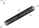
- Figs. 1 to 7 are schematic views showing a structure of a stent 100 of the embodiment.
- the stent 100 of the embodiment will be described with reference to Figs. 1 to 7 .
- the stent 100 of the embodiment has struts 110, which are linear components, and a plurality of link portions 120 connecting the struts 110 to each other.
- struts 110 which are linear components
- a plurality of link portions 120 connecting the struts 110 to each other an axial direction of a cylindrical shape formed using the struts 110 is simply denoted as an "axial direction D1" (refer to Figs. 1 and 2 )
- a circumferential direction of the cylindrical shape is simply denoted as a "circumferential direction D2" (refer to Fig. 2 )
- a radial direction of the cylindrical shape is simply denoted as a "radial direction R" (refer to Figs. 3 and 5 to 7).
- a side inserted into the blood vessel is denoted as a "distal side”
- a hand operation side that is opposite to the distal side is denoted as a "proximal side”.
- a direction of the blood flow in a location where the blood flow is not affected by the stent 100 is denoted as a blood flow direction, and in a case where the stent 100 is indwelled in the blood vessel, the blood flow direction coincides with the axial direction D1.
- the struts 110 form an outer periphery of the cylindrical shape in which a gap is formed, as shown in Fig. 1 .
- the struts 110 have a plurality of main strut portions 111 and a plurality of bent portions 112 interlocking the main strut portions 111 extending in directions different from each other.
- the struts 110 extend in the circumferential direction D2 while being folded back in a wave shape to form an endless tubular shape.
- the plurality of the struts 110 are provided along the axial direction D1 as shown in Fig. 2 .
- the plurality of struts 110 provided along the axial direction D1 are connected to each other through the link portions 120.
- the link portions 120 connect the struts 110 to each other (bent portions 112 to each other) in a gap between the struts 110 adjacent along the axial direction D1 as shown in Fig. 2 .
- the link portions 120 according to the present embodiment are provided along the axial direction D1. Note that, the link portions 120 may be provided along a direction intersecting with the axial direction D1.
- the plurality of link portions 120 are disposed at predetermined intervals in the circumferential direction D2. Note that, the location where the link portions 120 are disposed is not limited to the location shown in Fig. 2 and can be appropriately changed as long as the plurality of struts 110 provided along the axial direction D1 are connected to each other.
- the struts 110 and the link portions 120 are integrally formed.
- the material forming the stent 100 is, for example, a biodegradable material which is degraded in vivo.
- a biodegradable material examples include biodegradable synthetic polymeric materials such as polylactic acid, polyglycolic acid, lactic acid-glycolic acid copolymers, polycaprolactone, lactic acid-caprolactone copolymers, glycolic acid-caprolactone copolymers, and poly- ⁇ -glutamic acid, biodegradable natural polymer materials such as collagen, biodegradable metallic materials such as magnesium and zinc.
- the manufacturing method of the stent 100 is not particularly limited, but, examples thereof include a method of cutting out from a tube made of the above-described materials with laser or the like, a method by an injection molding, a method (laminate molding) of laminating using a 3D printer or the like. From a viewpoint of precisely finishing a complicated cross sectional shape, a method by an injection molding and a method of laminating using a 3D printer are preferable. Furthermore, from a viewpoint of manufacturing at a low cost and a viewpoint of finishing as a smooth surface condition, a method by an injection molding is particularly preferable.
- the stent 100 may include a coating body (not shown) containing a medicine on its surface.
- the coating body is formed on an outer surface side of the stent 100 which is to be come into contact with a blood vessel wall, but the present invention is not limited thereto.
- the coating body contains a medicine capable of suppressing proliferation of neointima, and a medicine carrier for carrying the medicine.
- the coating body may be formed of only the medicine.
- the medicine contained in the coating body is at least one selected from the group consisting, for example, of sirolimus, everolimus, zotarolimus, and paclitaxel.
- the constituent material of the medicine carrier is not particularly limited, but a biodegradable material is preferable, and the same material as that of the stent 100 is applicable.
- FIG. 3 is a cross-sectional view that is taken along line 3-3 of Fig. 2 that is taken along the axial direction D1 of the bent portions 112.
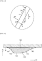
- Fig. 4 is an enlarged view of a portion A of Fig. 2 .
- Fig. 5 is a cross sectional view taken along line 5-5 of Fig.
- Fig. 4 is along the axial direction D1 of the main strut portion 111.
- Fig. 6 is a cross sectional view taken along line 6-6 of Fig. 4 that is along a width direction D3 of the main strut portion 111.
- Fig. 7 is a cross sectional view taken along line 7-7 of Fig. 2 that is along the axial direction D1 of a link portion 120.
- the stent 100 includes a first convex portion 130 (corresponds to convex portion) provided in the bent portions 112 of the struts 110, a second convex portion 140 (corresponds to convex portion) provided in the main strut portions 111 in the struts 110, a third convex portion 150 (corresponds to convex portion) provided in the link portions 120.
- the first convex portion 130, the second convex portion 140, and the third convex portion 150 protrude inward in a radial direction R, and have a streamline shape so as to improve the blood flow on an upstream side and a downstream side of the blood flow.
- the convex portion is provided in the bent portions 112 and the link portions 120 where the structure is relatively complicated and a vortex is likely to occur.
- the convex portion is provided between the bent portions 112 and the link portions 120, it is possible to reduce the vortex size in the bent portions 112 and the link portions 120 and to suppress the formation of a thrombus in the vicinity of the convex portion.
- the first convex portion 130 includes an upstream continuous portion 131, an upstream curved portion 132, a linear portion 133, a downstream curved portion 134, and a downstream continuous portion 135 provided in order from the upstream side (left side of Fig. 3 ) of the blood flow in a cross section along the axial direction D1 as shown in Fig. 3 .
- the upstream continuous portion 131, the upstream curved portion 132, the linear portion 133, the downstream curved portion 134, and the downstream continuous portion 135 are provided continuously. Note that, it is preferable that the above-described each portion is smoothly continuous at an interlocking point of each other from the viewpoint of suppressing the blood separation.
- smoothly means a state without stages and edges at the interlocking point.
- the upstream continuous portion 131 curves to be recessed outward (upper side of Fig. 3 ) in the radial direction R.
- the upstream continuous portion 131 is smoothly continuous with respect to the blood vessel wall W.
- the upstream curved portion 132 curves to protrude inward (lower side of Fig. 3 ) in the radial direction R.
- the upstream curved portion 132 and the linear portion 133 are continuous at a vertex 132a.
- the vertex 132a is positioned on the upstream side than the downstream side as shown in Fig. 3 . That is, when a length from an upstream edge 130a of the first convex portion 130 to the vertex 132a along the axial direction D1 is L1 (hereinafter, referred to as upstream length L1) and a length from a downstream edge 130b of the first convex portion 130 to the vertex 132a along the axial direction D1 is L2 (hereinafter, referred to as downstream length L2), the upstream length L1 is shorter than the downstream length L2.
- upstream length L1 a length from an upstream edge 130a of the first convex portion 130 to the vertex 132a along the axial direction D1
- L2 hereinafter, referred to as downstream length L2
- the linear portion 133 is provided along a tangent line T1 at the vertex 132a of the upstream curved portion 132.
- the linear portion 133 is provided substantially parallel to the axial direction D1. That is, the linear portion 133 is provided substantially parallel to the blood flow direction.
- a length W1 along the axial direction D1 of the linear portion 133 is not more than half of a length L (hereinafter, referred to as total length L) from the upstream edge 130a of the first convex portion 130 to the downstream edge 130b. With such a configuration, it is possible to restrain the length of the first convex portion 130 along the axial direction D1, and form a desired gap between the struts 110.
- the downstream curved portion 134 curves to protrude inward in the radial direction R.
- the downstream curved portion 134 is configured such that a tangent line T2 in an end portion 134a of the upstream side of the downstream curved portion 134 extends along the linear portion 133.
- the downstream continuous portion 135 curves to be recessed outward in the radial direction R.
- the downstream continuous portion 135 is smoothly continuous with respect to the blood vessel wall W.
- the total length L of the first convex portion 130 is longer than a height H along the radial direction R. With such a configuration, it is possible to make an incline in a streamline shape of the first convex portion 130 to be relatively smooth, and the blood flows more smoothly along the first convex portion 130. For this reason, it is possible to improve the blood flow, and to suppress the formation of a thrombus.
- the second convex portion 140 includes an upstream continuous portion 141, an upstream curved portion 142, a linear portion 143, a downstream curved portion 144, and a downstream continuous portion 145 provided in order from the upstream side (left side of Fig. 5 ) of the blood flow in a cross section along the axial direction D1 as shown in Fig. 5 .
- the upstream continuous portion 141, the upstream curved portion 142, the linear portion 143, the downstream curved portion 144, and the downstream continuous portion 145 are provided continuously.
- the second convex portion 140 includes the upstream continuous portion 141a, the upstream curved portion 142a, the linear portion 143a, the downstream curved portion 144a, and the downstream continuous portion 145a provided in order from left side of Fig. 6 in a cross section along a width direction D3 as shown in Fig. 6 .
- a cross section along the axial direction D1 in the main strut portions 111 of the struts 110 also has the same streamline shape.
- the third convex portion 150 includes an upstream continuous portion 151, an upstream curved portion 152, a linear portion 153, a downstream curved portion 154, and a downstream continuous portion 155 provided in order from the upstream side (left side of Fig. 7 ) of the blood flow in a cross section along the axial direction D1 as shown in Fig. 7 .
- the upstream continuous portion 151, the upstream curved portion 152, the linear portion 153, the downstream curved portion 154, and the downstream continuous portion 155 are provided continuously.
- the stent 100 is delivered to a stenosed site or an occlusion site formed in a blood vessel using medical equipment for stent delivery such as a balloon catheter.
- medical equipment for stent delivery such as a balloon catheter.
- a coronary stent in the vicinity of the blood vessel where the stent is indwelled, in a case where the stent is delivered from the upstream side to the downstream side of the blood flow, the downstream side of the stent is disposed on a distal side of the medical equipment for stent delivery and the upstream side of the stent is disposed on a hand operation side.
- a direction of the stent when the stent in the blood vessel is indwelled is positioned such that the upstream side of the stent is positioned on the upstream side and the downstream side of the stent is positioned on the downstream side along the blood flow direction.
- the direction for disposing the stent in the medical equipment for stent delivery is not only set based on the blood flow direction when delivering the stent, but is also preferably set in the consideration of the type of the blood vessel or running of the blood vessel in which the stent is indwelled.
- the delivered stent 100 expands in accordance with widening of a balloon in a stenosed site or an occlusion site within a blood vessel.
- the stent 100 may be a self-expanding type.
- the stent 500 of the comparative example first, blood flows to a vertex 501a (see symbol F1) along a linear slope 501 of the upstream side of an isosceles triangle, and is separated along an extension line of the linear slope 501 of the upstream side of an isosceles triangle (see symbol F2) . Then, the blood readheres on the blood vessel wall W at a position away from a downstream edge 500b of the isosceles triangle by a length L5 to the downstream side in the axial direction D1. At this time, on the downstream side of the stent 500, a vortex C2 is formed depending on the length L5.
- blood flow in a vicinity of the blood vessel wall W in a case where the stent 100 according to the embodiment is indwelled in an expanded state in the blood vessel will be described with reference to Fig. 8(A) .
- blood flow in a vicinity of the first convex portion 130 will be described as an example.
- the blood flowed to the vicinity of the first convex portion 130 is separated from the blood vessel wall W at a position away from the upstream edge 130a of the first convex portion 130 by a length L3 (hereinafter, referred to as separation length L3) on the upstream side, and flows along the upstream continuous portion 131 (see symbol f1).
- separation length L3 hereinafter, referred to as separation length L3
- the upstream continuous portion 131 and the upstream curved portion 132 are smoothly continuous at the interlocking point P1, it is possible to suppress the blood separation at the interlocking point P1. Accordingly, it is possible to suppress the formation of a thrombus at the interlocking point P1.
- the blood flows along the upstream curved portion 132 and flows to the vertex 132a (see symbol f2).
- the blood is slightly separated from the first convex portion 130 in the vicinity of the most distant location from a straight line that links the interlocking point P1 and the vertex 132a in the upstream curved portion 132.
- the upstream curved portion 132 curves and extends to protrude inward in the radial direction R
- the direction of blood flow in the vicinity of the first convex portion 130 gradually comes along with the axial direction D1 (blood flow direction) toward the vertex 132a. Therefore, the separation of blood from the vertex 132a reduces compared to the stent 500 (see Fig. 8 (B) ) including the linear slope 501 on the upstream side. For this reason, it is possible to reduce the size of the vortex on the downstream side of the vertex 132a, and to suppress the formation of a thrombus.
- the blood flows along the linear portion 133 (see symbol f3).
- the linear portion 133 is provided parallel to the axial direction D1 (blood flow direction)
- the blood slightly separated in the vicinity of the most distant location from a straight line that links the interlocking point P1 and the vertex 132a in the upstream curved portion 132 gradually flows along the axial direction D1 (blood flow direction) in the linear portion 133. Therefore, it is possible to reduce the size of a vortex at the vicinity of the linear portion 133, and to suppress the formation of a thrombus.
- the blood flows the end portion 134a of the upstream side of the downstream curved portion 134.
- the linear portion 133 and the downstream curved portion 134 are smoothly continuous in the end portion 134a of the downstream curved portion 134, it is possible to suppress the separation of blood from the first convex portion 130 in the end portion 134a. Therefore, it is possible to suppress the formation of a thrombus in the vicinity of the end portion 134a.
- the blood flows along the downstream curved portion 134 (see symbol f4).
- the downstream curved portion 134 extends to protrude inward in the radial direction R
- the blood flows along the downstream curved portion 134 compared to the stent 500 (see Fig. 8(B) ) including a linear slope 502 on the downstream side (compare symbol f4 in Fig. 8(A) symbol F3 in Fig. 8(B) ). Therefore, it is possible to suppress the separation of blood from the downstream curved portion 134, and to suppress formation of a thrombus in the vicinity of the downstream curved portion 134.
- the blood is gradually separated from the first convex portion 130 starting from the vicinity of the most distant location from a straight line that links the end portion 134a and the interlocking point P2 of the downstream curved portion 134 and the downstream continuous portion 135 in the downstream curved portion 134 (see symbol f5).
- the blood readheres on the blood vessel wall W at a position away from a downstream edge 130b of the first convex portion 130 by a length L4 (hereinafter, referred to as readhesion length L4) to the downstream side in the axial direction D1.
- readhesion length L4 a length L4 (hereinafter, referred to as readhesion length L4) to the downstream side in the axial direction D1.
- a vortex C1 is formed depending on the length L4.
- the stent 100 according to the present embodiment includes the first convex portion 130, the readhesion length is short compared to the stent according to the comparative example with reference to Fig. 8(A) and Fig. 8(B) . Then, due to short readhesion length, stagnation on the downstream side of the stent 100 is suppressed, and the size of the vortex C1 is reduced. Therefore, according to the stent 100 according to the embodiment, compared with the stent 500 according to the comparative example, it is possible to suppress the formation of a thrombus on the downstream side of the stent 100.
- Fig. 9 shows simulation results of a fluid analysis.
- a horizontal axis shows a ratio of the upstream length L1 with respect to the total length L.
- diamond-shaped plots indicate separation length L3
- rectangular plots indicate readhesion length L4, respectively.
- the separation length L3 is 0.03 mm or less from a viewpoint of suppressing the formation of a thrombus in the vicinity of the upstream edge 130a. Therefore, it is preferable that the ratio of the upstream length L1 with respect to the total length L is 12.5% (1/8) or more based on the graph in Fig. 9 .
- the readhesion length L4 is 0.125 mm or less from a viewpoint of suppressing the formation of a thrombus in the vicinity of the downstream edge 130b. Therefore, it is preferable that the ratio of the upstream length L1 with respect to the total length L is 37.5% (3/8) or less based on the graph in Fig. 9 .
- the ratio of lengths between the upstream length L1 and the downstream length L2 is within a range of 1:7 to 3:5.
- the stent 100 of the present embodiment is the stent 100 including the linear struts 110 that form an outer periphery of a cylindrical shape in which a gap is formed.
- Each strut 110 includes the first convex portion 130 that protrudes inward in the radial direction R in at least a portion in a cross section along the axial direction D1 of the cylindrical shape.
- the first convex portion 130 includes the vertex 132a that is formed to be positioned on the upstream side of blood flow than the downstream side of blood flow and the upstream curved portion 132 that curves and extends to protrude inward in the radial direction R from the vertex 132a toward the upstream in a cross section along the axial direction D1 of the cylindrical shape.
- a curved shape of the upstream curved portion 132 of the first convex portion 130 is disposed along the blood flow direction. For this reason, the blood flows along the upstream curved portion 132.
- the upstream curved portion 132 curves and extends to protrude inward in the radial direction R, the direction of blood flow in the vicinity of the upstream curved portion 132 gradually comes along with the blood flow direction toward the vertex 132a. Therefore, the separation of the blood from the vertex 132a reduces.
- the vertex 132a is provided on the upstream side of the first convex portion 130, it is possible to lengthen the length of the downstream side from the vertex 132a. Accordingly, compared with a case where the length to the downstream side is respectively short, since the blood flows more smoothly along the first convex portion 130, it is possible to improve the blood flow in the vicinity of the stent 100. From the above, in the vicinity of the downstream side of the vertex 132a, it is possible to reduce the size of a vortex and to suppress the formation of a thrombus caused by disturbance in the blood flow.
- the first convex portion 130 is provided on the downstream side from the vertex 132a in a cross section along the axial direction D1, and further includes the downstream curved portion 134 that curves and extends to protrude inward in the radial direction. For this reason, the blood flows along the downstream curved portion 134 more compared to the stent 500 including the slope 502 on the downstream side. Therefore, it is possible to improve the blood flow, and to suppress the formation of a thrombus in the vicinity of the downstream curved portion 134.
- the first convex portion 130 is configured so that the ratio of the upstream length L1 and the downstream length L2 is within a range of 1:7 to 3:5 in a cross section along the axial direction D1. According to the configuration, as described above, it is possible to set the separation length L3 and the readhesion length L4 to be a desired length, and to suitably suppress the formation of a thrombus.
- the first convex portion 130 further includes the linear portion 133 that interlocks the upstream curved portion 132 and the downstream curved portion 134, and is provided along a tangent line in the vertex 132a of the upstream curved portion 132, in a cross section along the axial direction D1. For this reason, the blood slightly separated from the vertex 132a gradually flows along the axial direction D1 (blood flow direction) in the linear portion 133. Accordingly, it is possible to reduce the size of a vortex in the vicinity of the linear portion 133.
- the first convex portion 130 in a cross section along the axial direction D1, further includes the upstream continuous portion 131 that is continuous to the upstream edge 130a of the first convex portion 130 from the end portion (interlocking point P1) of the upstream side in the upstream curved portion 132 and curves to be recessed outward in the radial direction R, and the downstream continuous portion 135 that is continuous to the downstream edge 130b of the first convex portion 130 from the end portion (interlocking point P2) of the downstream side in the downstream curved portion 134 and curves to be recessed outward in the radial direction R.
- the upstream continuous portion 131 and the downstream continuous portion 135 are smoothly continuous with respect to the blood vessel wall W. Therefore, the blood flow in the upstream edge 130a and the downstream edge 130b of the first convex portion 130 improves, and it is possible to reduce the size of a vortex in the upstream edge 130a and the downstream edge 130b of the first convex portion 130, and to suppress the formation of a thrombus.
- the stent 100 further includes the plurality of link portions 120 that connects the struts 110 with each other in a gap.
- the struts 110 include the plurality of main strut portions 111 and the plurality of bent portions 112 that include the main strut portions 111 extending in directions different from each other.
- Each bent portion 112 includes the first convex portion 130, and each link portion 120 includes the third convex portion 150.
- the first convex portion 130 and the third convex portion 150 are provided respectively in the bent portions 112 and the link portions 120 where the structure is comparatively complicated and a vortex is likely to occur, it is possible to reduce the size of vortex in the bent portions 112 and the link portions 120, and to suppress the formation of a thrombus.
- the first convex portion 130 had the upstream continuous portion 131, the upstream curved portion 132, the linear portion 133, the downstream curved portion 134, and the downstream continuous portion 135.
- a shape of a first convex portion is not particularly limited as long as the upstream curved portion 132 is provided, and the vertex 132a on the downstream side of the upstream curved portion 132 is positioned on the downstream side than the upstream side.
- a configuration in which the upstream continuous portion 131 is not provided and the upstream curved portion 132, the linear portion 133, the downstream curved portion 134, and the downstream continuous portion 135 are provided may be adopted as the first convex portion 230 in Fig. 10 .
- the first convex portion 130 had the upstream continuous portion 131, the upstream curved portion 132, the linear portion 133, the downstream curved portion 134, and the downstream continuous portion 135.
- a configuration that includes only the upstream curved portion 132 and the downstream curved portion 134 without the upstream continuous portion 131, the linear portion 133, and the downstream continuous portion 135 may be adopted as shown in the first convex portion 330 in Fig. 11 .
- the second convex portion 140 is provided in the main strut portions 111.
- the main strut portions may have a rectangular cross section.
- the cross sections at locations other than the bent portions 112 and the link portions 120 become a rectangular shape, and the area in a cross sectional view increases compared to a streamline shape, when the stent expands, it is possible to impart a desired expansion force with respect to the blood vessel wall W, and to suitably maintain the open state of the blood vessel.
- the first convex portion 130 and the third convex portion 150 are provided respectively in the bent portions 112 and the link portions 120 where a vortex easily occurs, it is possible to suppress formation of a thrombus.
- the link portions 120 are integrally configured with the struts 110.
- the link portions 120 may be configured separately from the struts 110.
- the link portions 120 are configured with, for example, a biodegradable material.
- the struts 110 may be configured with a non-biodegradable material. Examples of such a material include stainless steel, a cobalt-based alloy such as a cobalt-chromium alloy (for example, a CoCrWNi alloy), elastic metal such as a platinum-chromium alloy (for example, a PtFeCrNi alloy), and a super-elastic alloy such as a nickel-titanium alloy.
- the stent 100 is configured such that the plurality of struts 110 are continuous in the axial direction D1.
- the strut of the stent may be configured in a spiral shape.
- first convex portion 130, the second convex portion 140, and the third convex portion 150 have a substantially same shape.
- first convex portion 130, the second convex portion 140, and the third convex portion 150 may have different shapes as long as the upstream curved portions 132, 142, and 152 are provided.
Landscapes
- Health & Medical Sciences (AREA)
- Engineering & Computer Science (AREA)
- Biomedical Technology (AREA)
- Cardiology (AREA)
- Oral & Maxillofacial Surgery (AREA)
- Transplantation (AREA)
- Heart & Thoracic Surgery (AREA)
- Vascular Medicine (AREA)
- Life Sciences & Earth Sciences (AREA)
- Animal Behavior & Ethology (AREA)
- General Health & Medical Sciences (AREA)
- Public Health (AREA)
- Veterinary Medicine (AREA)
- Physics & Mathematics (AREA)
- Optics & Photonics (AREA)
- Media Introduction/Drainage Providing Device (AREA)
Abstract
Description
- The present invention relates to a stent.
- A stent, for example, is indwelled in an expanded state in a stenosed site or an occlusion site formed in a blood vessel and maintains an open state of the blood vessel. The stent has linear struts, which form an outer periphery of a cylindrical shape in which a gap is formed.
- As such a stent, generally, a stent in which a cross section of the struts is formed in a rectangular shape is used. However, in a case where the stent in which a cross section of struts is formed in a rectangular shape is indwelled in the blood vessel, there is a concern that blood flow in a vicinity of the struts is disturbed by a wall on an upstream side of the struts and blood does not flow well.
- Regarding this matter, for example, in PTL 1 described below, a stent including a shape (shape of isosceles triangle) that has a slope with respect to a blood flow direction as a cross-sectional shape of the struts is disclosed. According to the stent having such a configuration, since a slope is provided on an upstream side and a downstream side of the blood flow direction, it is possible to improve the blood flow in the vicinity of the struts, and to suppress formation of a thrombus around the struts.
- PTL 1:
JP-A-2015-177956 - However, in the stent disclosed in PTL 1, because the blood flow is separated from vertexes after the blood flows to the vertexes of the isosceles triangle, there is a possibility that disturbance (vortex) in the blood flow is caused and the thrombus is formed.
- From this viewpoint, there is a room for improvement in the stent disclosed in PTL 1 in terms of suppressing formation of the thrombus.
- An object of the present invention is to provide a stent capable of suppressing formation of a thrombus caused by disturbance in blood flow. Solution to Problem
- According to the present invention for achieving the above-described object, there is provided a stent including linear struts that form an outer periphery of a cylindrical shape in which a gap is formed, in which each strut has a convex portion that protrudes inward in a radial direction in at least a portion in a cross section along an axial direction of the cylindrical shape, and, in a state in which the stent is indwelled in a lumen in a living body, the convex portion has a vertex that is formed to be positioned on an upstream side of blood flow than a downstream side of blood flow and an upstream curved portion that curves and extends to protrude inward in the radial direction from the vertex toward the upstream side. Advantageous Effects of Invention
- In a case where the stent that has the above-described configuration is inserted into a blood vessel, the curved shape of the upstream curved portion of the convex portion is disposed along the blood flow direction. For this reason, the blood flows along the upstream curved portion. Here, since the upstream curved portion curves and extends to protrude inward in the radial direction, the blood gradually flows in a direction along the blood flow direction toward the vertex. Therefore, the separation of the blood from the vertex reduces. In addition, since the vertex is provided at the upstream side, it is possible to lengthen the length of the downstream side from the vertex. Therefore, compared with a case where the length of the downstream side is respectively short, since the blood flows more smoothly along the convex portion, it is possible to improve the blood flow in the vicinity of the stent. From the above, it is possible to provide a stent capable of reducing a size of a vortex, and suppressing the formation of a thrombus caused by disturbance in the blood flow in the downstream vicinity of the vertex.
-
- [
Fig. 1] Fig. 1 is a perspective view of a stent of an embodiment. - [
Fig. 2] Fig. 2 is a developed view in which a part of the outer periphery of the stent of the embodiment is developed by being linearly cut along an axial direction. - [
Fig. 3] Fig. 3 is a cross-sectional view taken along line 3-3 ofFig. 2 that is along an axial direction of a bent portion. - [
Fig. 4] Fig. 4 is an enlarged view of a portion A ofFig. 2 . - [
Fig. 5] Fig. 5 is a cross sectional view taken along line 5-5 ofFig. 4 that is along an axial direction of a main strut portion. - [
Fig. 6] Fig. 6 is a cross sectional view taken along line 6-6 ofFig. 4 that is along a width direction of the main strut portion. - [
Fig. 7] Fig. 7 is a cross sectional view taken along line 7-7 ofFig. 2 that is along an axial direction of a link portion. - [
Fig. 8] Fig. 8 is a view for illustrating an action and an effect of the stent of the embodiment.Fig. 8(A) shows blood movement in the vicinity of the stent of the embodiment.Fig. 8(B) shows blood movement in the vicinity of a stent of a comparative example. - [
Fig. 9] Fig. 9 is a graph that explains a preferable range of a ratio between an upstream length and a downstream length. - [
Fig. 10] Fig. 10 is a cross sectional view corresponding toFig. 3 of a stent according to Modification Example 1. - [
Fig. 11] Fig. 11 is a cross sectional view corresponding toFig. 3 of a stent according to Modification Example 2. - Hereinafter, an embodiment of the present invention will be described with reference to the accompanying drawings. Note that, dimensional ratios in the drawings are exaggerated and are different from the actual ratios for the convenience of description.
-
Figs. 1 to 7 are schematic views showing a structure of astent 100 of the embodiment. Hereinafter, thestent 100 of the embodiment will be described with reference toFigs. 1 to 7 . - As shown in
Figs. 1 and2 , thestent 100 of the embodiment hasstruts 110, which are linear components, and a plurality oflink portions 120 connecting thestruts 110 to each other. Note that, in the specification, an axial direction of a cylindrical shape formed using thestruts 110 is simply denoted as an "axial direction D1" (refer toFigs. 1 and2 ), a circumferential direction of the cylindrical shape is simply denoted as a "circumferential direction D2" (refer toFig. 2 ), a radial direction of the cylindrical shape is simply denoted as a "radial direction R" (refer toFigs. 3 and5 to 7). In addition, a side inserted into the blood vessel is denoted as a "distal side", and a hand operation side that is opposite to the distal side is denoted as a "proximal side". In addition, a direction of the blood flow in a location where the blood flow is not affected by thestent 100 is denoted as a blood flow direction, and in a case where thestent 100 is indwelled in the blood vessel, the blood flow direction coincides with the axial direction D1. - The
struts 110 form an outer periphery of the cylindrical shape in which a gap is formed, as shown inFig. 1 . As shown inFig. 2 , thestruts 110 have a plurality ofmain strut portions 111 and a plurality ofbent portions 112 interlocking themain strut portions 111 extending in directions different from each other. Thestruts 110 extend in the circumferential direction D2 while being folded back in a wave shape to form an endless tubular shape. - The plurality of the
struts 110 are provided along the axial direction D1 as shown inFig. 2 . The plurality ofstruts 110 provided along the axial direction D1 are connected to each other through thelink portions 120. - The
link portions 120 connect thestruts 110 to each other (bent portions 112 to each other) in a gap between thestruts 110 adjacent along the axial direction D1 as shown inFig. 2 . - The
link portions 120 according to the present embodiment are provided along the axial direction D1. Note that, thelink portions 120 may be provided along a direction intersecting with the axial direction D1. - The plurality of
link portions 120 are disposed at predetermined intervals in the circumferential direction D2. Note that, the location where thelink portions 120 are disposed is not limited to the location shown inFig. 2 and can be appropriately changed as long as the plurality ofstruts 110 provided along the axial direction D1 are connected to each other. - In the
stent 100, thestruts 110 and thelink portions 120 are integrally formed. - The material forming the
stent 100 is, for example, a biodegradable material which is degraded in vivo. Examples of such a material include biodegradable synthetic polymeric materials such as polylactic acid, polyglycolic acid, lactic acid-glycolic acid copolymers, polycaprolactone, lactic acid-caprolactone copolymers, glycolic acid-caprolactone copolymers, and poly-γ-glutamic acid, biodegradable natural polymer materials such as collagen, biodegradable metallic materials such as magnesium and zinc. - The manufacturing method of the
stent 100 is not particularly limited, but, examples thereof include a method of cutting out from a tube made of the above-described materials with laser or the like, a method by an injection molding, a method (laminate molding) of laminating using a 3D printer or the like. From a viewpoint of precisely finishing a complicated cross sectional shape, a method by an injection molding and a method of laminating using a 3D printer are preferable. Furthermore, from a viewpoint of manufacturing at a low cost and a viewpoint of finishing as a smooth surface condition, a method by an injection molding is particularly preferable. - In addition, the
stent 100 may include a coating body (not shown) containing a medicine on its surface. The coating body is formed on an outer surface side of thestent 100 which is to be come into contact with a blood vessel wall, but the present invention is not limited thereto. - The coating body contains a medicine capable of suppressing proliferation of neointima, and a medicine carrier for carrying the medicine. Note that the coating body may be formed of only the medicine. The medicine contained in the coating body is at least one selected from the group consisting, for example, of sirolimus, everolimus, zotarolimus, and paclitaxel. The constituent material of the medicine carrier is not particularly limited, but a biodegradable material is preferable, and the same material as that of the
stent 100 is applicable. - Next, a cross-sectional shape of the
stent 100 will be described with reference toFigs. 3 to 7 . Note that, inFigs. 3 and5 to 7 , a state where thestent 100 is compressed to a blood vessel wall W is shown. In addition, in each drawing, an upper side of the drawing is the blood vessel wall W side, and a lower side thereof is a blood flow side.Fig. 3 is a cross-sectional view that is taken along line 3-3 ofFig. 2 that is taken along the axial direction D1 of thebent portions 112.Fig. 4 is an enlarged view of a portion A ofFig. 2 .Fig. 5 is a cross sectional view taken along line 5-5 ofFig. 4 that is along the axial direction D1 of themain strut portion 111.Fig. 6 is a cross sectional view taken along line 6-6 ofFig. 4 that is along a width direction D3 of themain strut portion 111.Fig. 7 is a cross sectional view taken along line 7-7 ofFig. 2 that is along the axial direction D1 of alink portion 120. - The
stent 100 includes a first convex portion 130 (corresponds to convex portion) provided in thebent portions 112 of thestruts 110, a second convex portion 140 (corresponds to convex portion) provided in themain strut portions 111 in thestruts 110, a third convex portion 150 (corresponds to convex portion) provided in thelink portions 120. The firstconvex portion 130, the secondconvex portion 140, and the thirdconvex portion 150 protrude inward in a radial direction R, and have a streamline shape so as to improve the blood flow on an upstream side and a downstream side of the blood flow. - Note that, it is preferable that the convex portion is provided in the
bent portions 112 and thelink portions 120 where the structure is relatively complicated and a vortex is likely to occur. As the convex portion is provided between thebent portions 112 and thelink portions 120, it is possible to reduce the vortex size in thebent portions 112 and thelink portions 120 and to suppress the formation of a thrombus in the vicinity of the convex portion. - First, a configuration of the first
convex portion 130 provided in thebent portions 112 will be described with reference toFig. 3 . - The first
convex portion 130 includes an upstreamcontinuous portion 131, an upstreamcurved portion 132, alinear portion 133, a downstreamcurved portion 134, and a downstreamcontinuous portion 135 provided in order from the upstream side (left side ofFig. 3 ) of the blood flow in a cross section along the axial direction D1 as shown inFig. 3 . The upstreamcontinuous portion 131, the upstreamcurved portion 132, thelinear portion 133, the downstreamcurved portion 134, and the downstreamcontinuous portion 135 are provided continuously. Note that, it is preferable that the above-described each portion is smoothly continuous at an interlocking point of each other from the viewpoint of suppressing the blood separation. In the present specification, "smoothly" means a state without stages and edges at the interlocking point. - The upstream
continuous portion 131 curves to be recessed outward (upper side ofFig. 3 ) in the radial direction R. In addition, when thestent 100 is indwelled in the blood vessel, it is preferable that the upstreamcontinuous portion 131 is smoothly continuous with respect to the blood vessel wall W. - The upstream
curved portion 132 curves to protrude inward (lower side ofFig. 3 ) in the radial direction R. The upstreamcurved portion 132 and thelinear portion 133 are continuous at avertex 132a. - The
vertex 132a is positioned on the upstream side than the downstream side as shown inFig. 3 . That is, when a length from anupstream edge 130a of the firstconvex portion 130 to thevertex 132a along the axial direction D1 is L1 (hereinafter, referred to as upstream length L1) and a length from adownstream edge 130b of the firstconvex portion 130 to thevertex 132a along the axial direction D1 is L2 (hereinafter, referred to as downstream length L2), the upstream length L1 is shorter than the downstream length L2. - The
linear portion 133 is provided along a tangent line T1 at thevertex 132a of the upstreamcurved portion 132. Thelinear portion 133 is provided substantially parallel to the axial direction D1. That is, thelinear portion 133 is provided substantially parallel to the blood flow direction. - It is preferable that a length W1 along the axial direction D1 of the
linear portion 133 is not more than half of a length L (hereinafter, referred to as total length L) from theupstream edge 130a of the firstconvex portion 130 to thedownstream edge 130b. With such a configuration, it is possible to restrain the length of the firstconvex portion 130 along the axial direction D1, and form a desired gap between thestruts 110. - The downstream
curved portion 134 curves to protrude inward in the radial direction R. In addition, the downstreamcurved portion 134 is configured such that a tangent line T2 in anend portion 134a of the upstream side of the downstreamcurved portion 134 extends along thelinear portion 133. - The downstream
continuous portion 135 curves to be recessed outward in the radial direction R. In addition, when thestent 100 is indwelled in the blood vessel, it is preferable that the downstreamcontinuous portion 135 is smoothly continuous with respect to the blood vessel wall W. - It is preferable that the total length L of the first
convex portion 130 is longer than a height H along the radial direction R. With such a configuration, it is possible to make an incline in a streamline shape of the firstconvex portion 130 to be relatively smooth, and the blood flows more smoothly along the firstconvex portion 130. For this reason, it is possible to improve the blood flow, and to suppress the formation of a thrombus. - Next, a configuration of the second
convex portion 140 provided in themain strut portions 111 will be described with reference toFigs. 4 to 6 . Note that, since the configuration of the secondconvex portion 140 is substantially the same as the configuration of the firstconvex portion 130, a detailed description will be omitted. - The second
convex portion 140 includes an upstreamcontinuous portion 141, an upstreamcurved portion 142, alinear portion 143, a downstreamcurved portion 144, and a downstreamcontinuous portion 145 provided in order from the upstream side (left side ofFig. 5 ) of the blood flow in a cross section along the axial direction D1 as shown inFig. 5 . The upstreamcontinuous portion 141, the upstreamcurved portion 142, thelinear portion 143, the downstreamcurved portion 144, and the downstreamcontinuous portion 145 are provided continuously. - In addition, the second
convex portion 140 includes the upstreamcontinuous portion 141a, the upstreamcurved portion 142a, thelinear portion 143a, the downstreamcurved portion 144a, and the downstreamcontinuous portion 145a provided in order from left side ofFig. 6 in a cross section along a width direction D3 as shown inFig. 6 . - As is known from
Figs. 5 and6 , when the cross section along the width direction D3 in themain strut portions 111 of thestruts 110 has a uniform streamline shape along an extending direction D4 of themain strut portions 111, a cross section along the axial direction D1 in themain strut portions 111 of thestruts 110 also has the same streamline shape. - Next, a configuration of the third
convex portion 150 provided in thelink portions 120 will be described with reference toFig. 7 . Note that, since the configuration of the thirdconvex portion 150 is substantially the same as the configuration of the firstconvex portion 130, a detailed description will be omitted. - The third
convex portion 150 includes an upstreamcontinuous portion 151, an upstreamcurved portion 152, alinear portion 153, a downstreamcurved portion 154, and a downstreamcontinuous portion 155 provided in order from the upstream side (left side ofFig. 7 ) of the blood flow in a cross section along the axial direction D1 as shown inFig. 7 . The upstreamcontinuous portion 151, the upstreamcurved portion 152, thelinear portion 153, the downstreamcurved portion 154, and the downstreamcontinuous portion 155 are provided continuously. - Next, the action and the effect of the
stent 100 of the present embodiment will be described. - The
stent 100 is delivered to a stenosed site or an occlusion site formed in a blood vessel using medical equipment for stent delivery such as a balloon catheter. At this time, such as a coronary stent, in the vicinity of the blood vessel where the stent is indwelled, in a case where the stent is delivered from the upstream side to the downstream side of the blood flow, the downstream side of the stent is disposed on a distal side of the medical equipment for stent delivery and the upstream side of the stent is disposed on a hand operation side. - In this case, a direction of the stent when the stent in the blood vessel is indwelled is positioned such that the upstream side of the stent is positioned on the upstream side and the downstream side of the stent is positioned on the downstream side along the blood flow direction.
- Note that, the direction for disposing the stent in the medical equipment for stent delivery is not only set based on the blood flow direction when delivering the stent, but is also preferably set in the consideration of the type of the blood vessel or running of the blood vessel in which the stent is indwelled.
- The delivered
stent 100 expands in accordance with widening of a balloon in a stenosed site or an occlusion site within a blood vessel. Note that, thestent 100 may be a self-expanding type. - Hereinafter, blood flow of the
stent 100 according to the embodiment and astent 500 according to a comparative example will be compared with reference toFig. 8 (A) and Fig. 8(B) . - First, blood flow in a vicinity of the blood vessel wall W in a case where the
stent 500 of the comparative example having a triangular cross section is indwelled in an expanded state in the blood vessel will be described with reference toFig. 8(B) . - In the
stent 500 of the comparative example, first, blood flows to avertex 501a (see symbol F1) along alinear slope 501 of the upstream side of an isosceles triangle, and is separated along an extension line of thelinear slope 501 of the upstream side of an isosceles triangle (see symbol F2) . Then, the blood readheres on the blood vessel wall W at a position away from adownstream edge 500b of the isosceles triangle by a length L5 to the downstream side in the axial direction D1. At this time, on the downstream side of thestent 500, a vortex C2 is formed depending on the length L5. - Next, blood flow in a vicinity of the blood vessel wall W in a case where the
stent 100 according to the embodiment is indwelled in an expanded state in the blood vessel will be described with reference toFig. 8(A) . Here, blood flow in a vicinity of the firstconvex portion 130 will be described as an example. - First, the blood flowed to the vicinity of the first
convex portion 130 is separated from the blood vessel wall W at a position away from theupstream edge 130a of the firstconvex portion 130 by a length L3 (hereinafter, referred to as separation length L3) on the upstream side, and flows along the upstream continuous portion 131 (see symbol f1). Here, in order to be smoothly continuous with respect to the blood vessel wall W, it is possible to reduce the size of a vortex of the vicinity of theupstream edge 130a of the firstconvex portion 130, and to suppress the formation of a thrombus in the upstreamcontinuous portion 131. - Next, blood flows an interlocking point P1 that interlocks the upstream
continuous portion 131 and the upstreamcurved portion 132. Here, since the upstreamcontinuous portion 131 and the upstreamcurved portion 132 are smoothly continuous at the interlocking point P1, it is possible to suppress the blood separation at the interlocking point P1. Accordingly, it is possible to suppress the formation of a thrombus at the interlocking point P1. - Then, the blood flows along the upstream
curved portion 132 and flows to thevertex 132a (see symbol f2). At this time, the blood is slightly separated from the firstconvex portion 130 in the vicinity of the most distant location from a straight line that links the interlocking point P1 and thevertex 132a in the upstreamcurved portion 132. Here, since the upstreamcurved portion 132 curves and extends to protrude inward in the radial direction R, the direction of blood flow in the vicinity of the firstconvex portion 130 gradually comes along with the axial direction D1 (blood flow direction) toward thevertex 132a. Therefore, the separation of blood from thevertex 132a reduces compared to the stent 500 (seeFig. 8 (B) ) including thelinear slope 501 on the upstream side. For this reason, it is possible to reduce the size of the vortex on the downstream side of thevertex 132a, and to suppress the formation of a thrombus. - Next, the blood flows along the linear portion 133 (see symbol f3). Here, since the
linear portion 133 is provided parallel to the axial direction D1 (blood flow direction), even the blood slightly separated in the vicinity of the most distant location from a straight line that links the interlocking point P1 and thevertex 132a in the upstreamcurved portion 132 gradually flows along the axial direction D1 (blood flow direction) in thelinear portion 133. Therefore, it is possible to reduce the size of a vortex at the vicinity of thelinear portion 133, and to suppress the formation of a thrombus. - Next, the blood flows the
end portion 134a of the upstream side of the downstreamcurved portion 134. Here, since thelinear portion 133 and the downstreamcurved portion 134 are smoothly continuous in theend portion 134a of the downstreamcurved portion 134, it is possible to suppress the separation of blood from the firstconvex portion 130 in theend portion 134a. Therefore, it is possible to suppress the formation of a thrombus in the vicinity of theend portion 134a. - Next, the blood flows along the downstream curved portion 134 (see symbol f4). Here, since the downstream
curved portion 134 extends to protrude inward in the radial direction R, the blood flows along the downstreamcurved portion 134 compared to the stent 500 (seeFig. 8(B) ) including alinear slope 502 on the downstream side (compare symbol f4 inFig. 8(A) symbol F3 inFig. 8(B) ). Therefore, it is possible to suppress the separation of blood from the downstreamcurved portion 134, and to suppress formation of a thrombus in the vicinity of the downstreamcurved portion 134. - Next, the blood is gradually separated from the first
convex portion 130 starting from the vicinity of the most distant location from a straight line that links theend portion 134a and the interlocking point P2 of the downstreamcurved portion 134 and the downstreamcontinuous portion 135 in the downstream curved portion 134 (see symbol f5). - Next, the blood readheres on the blood vessel wall W at a position away from a
downstream edge 130b of the firstconvex portion 130 by a length L4 (hereinafter, referred to as readhesion length L4) to the downstream side in the axial direction D1. At this time, on the downstream side of the firstconvex portion 130, a vortex C1 is formed depending on the length L4. - Since the
stent 100 according to the present embodiment includes the firstconvex portion 130, the readhesion length is short compared to the stent according to the comparative example with reference toFig. 8(A) and Fig. 8(B) . Then, due to short readhesion length, stagnation on the downstream side of thestent 100 is suppressed, and the size of the vortex C1 is reduced. Therefore, according to thestent 100 according to the embodiment, compared with thestent 500 according to the comparative example, it is possible to suppress the formation of a thrombus on the downstream side of thestent 100. - Next, a preferred range of a ratio between the upstream length L1 and the downstream length L2 will be described with reference to
Fig. 9. Fig. 9 shows simulation results of a fluid analysis. - In
Fig. 9 , a horizontal axis shows a ratio of the upstream length L1 with respect to the total length L. In addition, between vertical axes, diamond-shaped plots indicate separation length L3, and rectangular plots indicate readhesion length L4, respectively. - It is preferable that the separation length L3 is 0.03 mm or less from a viewpoint of suppressing the formation of a thrombus in the vicinity of the
upstream edge 130a. Therefore, it is preferable that the ratio of the upstream length L1 with respect to the total length L is 12.5% (1/8) or more based on the graph inFig. 9 . - On the other hand, it is preferable that the readhesion length L4 is 0.125 mm or less from a viewpoint of suppressing the formation of a thrombus in the vicinity of the
downstream edge 130b. Therefore, it is preferable that the ratio of the upstream length L1 with respect to the total length L is 37.5% (3/8) or less based on the graph inFig. 9 . - Therefore, it is preferable that the ratio of lengths between the upstream length L1 and the downstream length L2 is within a range of 1:7 to 3:5.
- As described above, the
stent 100 of the present embodiment is thestent 100 including thelinear struts 110 that form an outer periphery of a cylindrical shape in which a gap is formed. Eachstrut 110 includes the firstconvex portion 130 that protrudes inward in the radial direction R in at least a portion in a cross section along the axial direction D1 of the cylindrical shape. In a state where thestent 100 is indwelled in a lumen in a living body, the firstconvex portion 130 includes thevertex 132a that is formed to be positioned on the upstream side of blood flow than the downstream side of blood flow and the upstreamcurved portion 132 that curves and extends to protrude inward in the radial direction R from thevertex 132a toward the upstream in a cross section along the axial direction D1 of the cylindrical shape. - In a case where the
stent 100 having the above-described configuration is inserted into a blood vessel, a curved shape of the upstreamcurved portion 132 of the firstconvex portion 130 is disposed along the blood flow direction. For this reason, the blood flows along the upstreamcurved portion 132. Here, since the upstreamcurved portion 132 curves and extends to protrude inward in the radial direction R, the direction of blood flow in the vicinity of the upstreamcurved portion 132 gradually comes along with the blood flow direction toward thevertex 132a. Therefore, the separation of the blood from thevertex 132a reduces. In addition, since thevertex 132a is provided on the upstream side of the firstconvex portion 130, it is possible to lengthen the length of the downstream side from thevertex 132a. Accordingly, compared with a case where the length to the downstream side is respectively short, since the blood flows more smoothly along the firstconvex portion 130, it is possible to improve the blood flow in the vicinity of thestent 100. From the above, in the vicinity of the downstream side of thevertex 132a, it is possible to reduce the size of a vortex and to suppress the formation of a thrombus caused by disturbance in the blood flow. - In addition, the first
convex portion 130 is provided on the downstream side from thevertex 132a in a cross section along the axial direction D1, and further includes the downstreamcurved portion 134 that curves and extends to protrude inward in the radial direction. For this reason, the blood flows along the downstreamcurved portion 134 more compared to thestent 500 including theslope 502 on the downstream side. Therefore, it is possible to improve the blood flow, and to suppress the formation of a thrombus in the vicinity of the downstreamcurved portion 134. - In addition, the first
convex portion 130 is configured so that the ratio of the upstream length L1 and the downstream length L2 is within a range of 1:7 to 3:5 in a cross section along the axial direction D1. According to the configuration, as described above, it is possible to set the separation length L3 and the readhesion length L4 to be a desired length, and to suitably suppress the formation of a thrombus. - In addition, the first
convex portion 130 further includes thelinear portion 133 that interlocks the upstreamcurved portion 132 and the downstreamcurved portion 134, and is provided along a tangent line in thevertex 132a of the upstreamcurved portion 132, in a cross section along the axial direction D1. For this reason, the blood slightly separated from thevertex 132a gradually flows along the axial direction D1 (blood flow direction) in thelinear portion 133. Accordingly, it is possible to reduce the size of a vortex in the vicinity of thelinear portion 133. - In addition, the first
convex portion 130, in a cross section along the axial direction D1, further includes the upstreamcontinuous portion 131 that is continuous to theupstream edge 130a of the firstconvex portion 130 from the end portion (interlocking point P1) of the upstream side in the upstreamcurved portion 132 and curves to be recessed outward in the radial direction R, and the downstreamcontinuous portion 135 that is continuous to thedownstream edge 130b of the firstconvex portion 130 from the end portion (interlocking point P2) of the downstream side in the downstreamcurved portion 134 and curves to be recessed outward in the radial direction R. Therefore, when thestent 100 is indwelled in the blood vessel, the upstreamcontinuous portion 131 and the downstreamcontinuous portion 135 are smoothly continuous with respect to the blood vessel wall W. Therefore, the blood flow in theupstream edge 130a and thedownstream edge 130b of the firstconvex portion 130 improves, and it is possible to reduce the size of a vortex in theupstream edge 130a and thedownstream edge 130b of the firstconvex portion 130, and to suppress the formation of a thrombus. - In addition, the
stent 100 further includes the plurality oflink portions 120 that connects thestruts 110 with each other in a gap. Thestruts 110 include the plurality ofmain strut portions 111 and the plurality ofbent portions 112 that include themain strut portions 111 extending in directions different from each other. Eachbent portion 112 includes the firstconvex portion 130, and eachlink portion 120 includes the thirdconvex portion 150. Accordingly, since the firstconvex portion 130 and the thirdconvex portion 150 are provided respectively in thebent portions 112 and thelink portions 120 where the structure is comparatively complicated and a vortex is likely to occur, it is possible to reduce the size of vortex in thebent portions 112 and thelink portions 120, and to suppress the formation of a thrombus. - The first
convex portion 130 according to the above-described embodiment had the upstreamcontinuous portion 131, the upstreamcurved portion 132, thelinear portion 133, the downstreamcurved portion 134, and the downstreamcontinuous portion 135. However, a shape of a first convex portion is not particularly limited as long as the upstreamcurved portion 132 is provided, and thevertex 132a on the downstream side of the upstreamcurved portion 132 is positioned on the downstream side than the upstream side. For example, a configuration in which the upstreamcontinuous portion 131 is not provided and the upstreamcurved portion 132, thelinear portion 133, the downstreamcurved portion 134, and the downstreamcontinuous portion 135 are provided may be adopted as the firstconvex portion 230 inFig. 10 . - In the above-described embodiment, the first
convex portion 130 had the upstreamcontinuous portion 131, the upstreamcurved portion 132, thelinear portion 133, the downstreamcurved portion 134, and the downstreamcontinuous portion 135. However, a configuration that includes only the upstreamcurved portion 132 and the downstreamcurved portion 134 without the upstreamcontinuous portion 131, thelinear portion 133, and the downstreamcontinuous portion 135 may be adopted as shown in the firstconvex portion 330 inFig. 11 . - In the above-described embodiment, the second
convex portion 140 is provided in themain strut portions 111. However, the main strut portions may have a rectangular cross section. In the case of a stent with such a configuration, since the cross sections at locations other than thebent portions 112 and thelink portions 120 become a rectangular shape, and the area in a cross sectional view increases compared to a streamline shape, when the stent expands, it is possible to impart a desired expansion force with respect to the blood vessel wall W, and to suitably maintain the open state of the blood vessel. In addition, since the firstconvex portion 130 and the thirdconvex portion 150 are provided respectively in thebent portions 112 and thelink portions 120 where a vortex easily occurs, it is possible to suppress formation of a thrombus. - The present invention is not limited to the embodiment and the modification examples described above, and can be variously modified within the claims.
- For example, in the above-described embodiment, the
link portions 120 are integrally configured with thestruts 110. However, thelink portions 120 may be configured separately from thestruts 110. At this time, thelink portions 120 are configured with, for example, a biodegradable material. On the other hand, thestruts 110, for example, may be configured with a non-biodegradable material. Examples of such a material include stainless steel, a cobalt-based alloy such as a cobalt-chromium alloy (for example, a CoCrWNi alloy), elastic metal such as a platinum-chromium alloy (for example, a PtFeCrNi alloy), and a super-elastic alloy such as a nickel-titanium alloy. - In addition, in the above-described embodiment, the
stent 100 is configured such that the plurality ofstruts 110 are continuous in the axial direction D1. However, the strut of the stent may be configured in a spiral shape. - In addition, in the above-described embodiment, the first
convex portion 130, the secondconvex portion 140, and the thirdconvex portion 150 have a substantially same shape. However, the firstconvex portion 130, the secondconvex portion 140, and the thirdconvex portion 150 may have different shapes as long as the upstreamcurved portions - In addition, even when the above-described convex portion is formed along the axial direction D1 before expansion deformation of the
stent 100, as long as the above-described convex portion is formed along the axial direction D1 after the expanded deformation of thestent 100, it is included in the present invention. - This application is based on Japanese Patent Application No.
2016-053080 filed on March 16, 2016 -
- 100 stent
- 110 strut
- 111 main strut portion
- 112 bent portion
- 120 link portion
- 130, 230, 330 first convex portion (convex portion)
- 140 second convex portion (convex portion)
- 150 third convex portion (convex portion)
- 130a upstream edge
- 130b downstream edge
- 131, 141, 151 upstream continuous portion
- 132, 142, 152 upstream curved portion
- 133, 143, 153 linear portion
- 134, 144, 154 downstream curved portion
- 135, 145, 155 downstream continuous portion
- D1 axial direction
- L1 upstream length (length along axial direction from upstream edge of convex portion to vertex)
- L2 downstream length (length along axial direction from downstream edge of convex portion to vertex)
- P1 interlocking point (end portion on upstream side in upstream curved portion)
- P2 interlocking point (end portion on downstream side in downstream curved portion)
- R radial direction
Claims (7)
- A stent comprising:linear struts that form an outer periphery of a cylindrical shape in which a gap is formed,wherein each strut has a convex portion that protrudes inward in a radial direction in at least a portion in a cross section along an axial direction of the cylindrical shape, andwherein, in a state in which the stent is indwelled in a lumen in a living body,the convex portion has,a vertex that is formed to be positioned on an upstream side of blood flow than a downstream side of blood flow, andan upstream curved portion that curves and extends to protrude inward in the radial direction from the vertex toward the upstream side.
- The stent according to Claim 1,
wherein, in the cross section along the axial direction,
the convex portion further has,
a downstream curved portion that is provided on the downstream side from the vertex and that curves and extends to protrude inward in the radial direction. - The stent according to Claim 2,
wherein, in the cross section along the axial direction, the convex portion is configured so that a ratio of a length along the axial direction from an upstream edge of the convex portion to the vertex and a length along the axial direction from a downstream edge of the convex portion to the vertex is within a range of 1:7 to 3:5. - The stent according to Claim 2 or 3,
wherein, in the cross section along the axial direction,
the convex portion further includes,
a linear portion that interlocks the upstream curved portion and the downstream curved portion and is provided along a tangent line at the vertex of the upstream curved portion. - The stent according to any one of Claims 2 to 4,
wherein, in the cross section along the axial direction,
the convex portion further includes,
an upstream continuous portion that is continuous from an end portion on the upstream side in the upstream curved portion to the upstream edge of the convex portion and curves to be recessed outward in the radial direction, and
a downstream continuous portion that is continuous from an end portion on the downstream side in the downstream curved portion to the downstream edge of the convex portion and curves to be recessed outward in the radial direction. - The stent according to any one of Claims 1 to 5, further comprising:a plurality of link portions that connects the struts to each other in the gap,wherein each strut has a plurality of main strut portions and a plurality of bent portions that interlocks the main strut portions that extend in different directions, andwherein at least one of the plurality of link portions and/or at least one of the plurality of bent portions has the convex portion.
- The stent according to any one of Claims 1 to 6, which is manufactured by injection molding or laminate molding.
Applications Claiming Priority (2)
| Application Number | Priority Date | Filing Date | Title |
|---|---|---|---|
| JP2016053080 | 2016-03-16 | ||
| PCT/JP2016/088237 WO2017158985A1 (en) | 2016-03-16 | 2016-12-21 | Stent |
Publications (2)
| Publication Number | Publication Date |
|---|---|
| EP3431049A1 true EP3431049A1 (en) | 2019-01-23 |
| EP3431049A4 EP3431049A4 (en) | 2019-10-02 |
Family
ID=59851823
Family Applications (1)
| Application Number | Title | Priority Date | Filing Date |
|---|---|---|---|
| EP16894602.8A Withdrawn EP3431049A4 (en) | 2016-03-16 | 2016-12-21 | Stent |
Country Status (5)
| Country | Link |
|---|---|
| US (1) | US20180368999A1 (en) |
| EP (1) | EP3431049A4 (en) |
| JP (1) | JPWO2017158985A1 (en) |
| CN (1) | CN108778194A (en) |
| WO (1) | WO2017158985A1 (en) |
Cited By (1)
| Publication number | Priority date | Publication date | Assignee | Title |
|---|---|---|---|---|
| EP3431050A4 (en) * | 2016-03-16 | 2019-10-16 | Terumo Kabushiki Kaisha | Stent |
Families Citing this family (2)
| Publication number | Priority date | Publication date | Assignee | Title |
|---|---|---|---|---|
| JP2022028088A (en) * | 2018-12-12 | 2022-02-15 | 住友電気工業株式会社 | Stent and method of manufacturing the stent |
| CN120267355A (en) * | 2021-04-30 | 2025-07-08 | 杭州亿科医疗科技有限公司 | Bolt taking support |
Family Cites Families (9)
| Publication number | Priority date | Publication date | Assignee | Title |
|---|---|---|---|---|
| US5344425A (en) * | 1990-09-14 | 1994-09-06 | Interface Biomedical Laboratories, Corp. | Intravascular stent and method for conditioning the surfaces thereof |
| US5718713A (en) * | 1997-04-10 | 1998-02-17 | Global Therapeutics, Inc. | Surgical stent having a streamlined contour |
| US6685737B1 (en) * | 2000-10-31 | 2004-02-03 | Advanced Cardiovascular Systems, Inc. | Endoluminal stent cross section for optimum biocompatibility |
| US8292944B2 (en) * | 2004-12-17 | 2012-10-23 | Reva Medical, Inc. | Slide-and-lock stent |
| US20080306581A1 (en) * | 2007-06-07 | 2008-12-11 | Medtronic Vascular, Inc. | Streamlined Stents |
| WO2009070624A1 (en) * | 2007-11-27 | 2009-06-04 | The Trustees Of The University Of Pennsylvania | Vascular stent |
| DE102008038367A1 (en) * | 2008-08-19 | 2010-02-25 | Biotronik Vi Patent Ag | Stent and method and apparatus for making the stent |
| US8747649B2 (en) * | 2011-05-13 | 2014-06-10 | Abbott Cardiovascular Systems Inc. | Electrochemical formation of foil-shaped stent struts |
| WO2014030982A1 (en) * | 2012-08-24 | 2014-02-27 | 연세대학교 산학협력단 | Wire stent |
-
2016
- 2016-12-21 JP JP2018505265A patent/JPWO2017158985A1/en active Pending
- 2016-12-21 CN CN201680083609.7A patent/CN108778194A/en active Pending
- 2016-12-21 WO PCT/JP2016/088237 patent/WO2017158985A1/en not_active Ceased
- 2016-12-21 EP EP16894602.8A patent/EP3431049A4/en not_active Withdrawn
-
2018
- 2018-08-31 US US16/118,687 patent/US20180368999A1/en not_active Abandoned
Cited By (2)
| Publication number | Priority date | Publication date | Assignee | Title |
|---|---|---|---|---|
| EP3431050A4 (en) * | 2016-03-16 | 2019-10-16 | Terumo Kabushiki Kaisha | Stent |
| US10786375B2 (en) | 2016-03-16 | 2020-09-29 | Terumo Kabushiki Kaisha | Stent |
Also Published As
| Publication number | Publication date |
|---|---|
| JPWO2017158985A1 (en) | 2019-01-24 |
| EP3431049A4 (en) | 2019-10-02 |
| WO2017158985A1 (en) | 2017-09-21 |
| CN108778194A (en) | 2018-11-09 |
| US20180368999A1 (en) | 2018-12-27 |
Similar Documents
| Publication | Publication Date | Title |
|---|---|---|
| US10098766B2 (en) | Stent and method and device for fabricating the stent | |
| EP2849688B1 (en) | Uniformly expandable stent | |
| US10828183B2 (en) | Low profile non-symmetrical stent | |
| JP5701776B2 (en) | Stent | |
| EP1729681B1 (en) | Partially biodegradable stent | |
| EP2537491A1 (en) | Helical stent | |
| EP2967828B1 (en) | Stent device having reduced foreshortening and recoil and method of making same | |
| US20090043374A1 (en) | Stent to be Placed in the Living Body | |
| EP3295902B1 (en) | Stent | |
| US20180368999A1 (en) | Stent | |
| EP3232993B1 (en) | Stent with anti-migration features | |
| US20080234800A1 (en) | Stent Including a Toggle Lock | |
| US9320628B2 (en) | Endoprosthesis devices including biostable and bioabsorable regions | |
| US20190133748A1 (en) | Longitudinally and radially flexible anastomosis stent | |
| US10786375B2 (en) | Stent | |
| EP3087957B1 (en) | Vascular stent | |
| US20170281374A1 (en) | Stent | |
| US20180116836A1 (en) | Stent | |
| WO2017130803A1 (en) | Stent | |
| US20070150042A1 (en) | Stents with beveled ends and methods of use thereof | |
| JP2024156724A (en) | Implant | |
| JP2017086094A (en) | Stent |
Legal Events
| Date | Code | Title | Description |
|---|---|---|---|
| STAA | Information on the status of an ep patent application or granted ep patent |
Free format text: STATUS: THE INTERNATIONAL PUBLICATION HAS BEEN MADE |
|
| PUAI | Public reference made under article 153(3) epc to a published international application that has entered the european phase |
Free format text: ORIGINAL CODE: 0009012 |
|
| STAA | Information on the status of an ep patent application or granted ep patent |
Free format text: STATUS: REQUEST FOR EXAMINATION WAS MADE |
|
| 17P | Request for examination filed |
Effective date: 20180824 |
|
| AK | Designated contracting states |
Kind code of ref document: A1 Designated state(s): AL AT BE BG CH CY CZ DE DK EE ES FI FR GB GR HR HU IE IS IT LI LT LU LV MC MK MT NL NO PL PT RO RS SE SI SK SM TR |
|
| AX | Request for extension of the european patent |
Extension state: BA ME |
|
| DAV | Request for validation of the european patent (deleted) | ||
| DAX | Request for extension of the european patent (deleted) | ||
| A4 | Supplementary search report drawn up and despatched |
Effective date: 20190829 |
|
| RIC1 | Information provided on ipc code assigned before grant |
Ipc: A61F 2/90 20130101ALI20190823BHEP Ipc: A61F 2/915 20130101ALI20190823BHEP Ipc: A61F 2/06 20130101ALI20190823BHEP Ipc: A61F 2/82 20130101AFI20190823BHEP |
|
| STAA | Information on the status of an ep patent application or granted ep patent |
Free format text: STATUS: THE APPLICATION IS DEEMED TO BE WITHDRAWN |
|
| 18D | Application deemed to be withdrawn |
Effective date: 20200603 |