EP3430824B1 - Procédés et systèmes de gestion d'une connectivité entre dispositifs - Google Patents
Procédés et systèmes de gestion d'une connectivité entre dispositifs Download PDFInfo
- Publication number
- EP3430824B1 EP3430824B1 EP17789888.9A EP17789888A EP3430824B1 EP 3430824 B1 EP3430824 B1 EP 3430824B1 EP 17789888 A EP17789888 A EP 17789888A EP 3430824 B1 EP3430824 B1 EP 3430824B1
- Authority
- EP
- European Patent Office
- Prior art keywords
- secondary devices
- devices
- connection
- primary
- user
- Prior art date
- Legal status (The legal status is an assumption and is not a legal conclusion. Google has not performed a legal analysis and makes no representation as to the accuracy of the status listed.)
- Active
Links
Images


Classifications
-
- H—ELECTRICITY
- H04—ELECTRIC COMMUNICATION TECHNIQUE
- H04L—TRANSMISSION OF DIGITAL INFORMATION, e.g. TELEGRAPHIC COMMUNICATION
- H04L41/00—Arrangements for maintenance, administration or management of data switching networks, e.g. of packet switching networks
- H04L41/22—Arrangements for maintenance, administration or management of data switching networks, e.g. of packet switching networks comprising specially adapted graphical user interfaces [GUI]
-
- H—ELECTRICITY
- H04—ELECTRIC COMMUNICATION TECHNIQUE
- H04L—TRANSMISSION OF DIGITAL INFORMATION, e.g. TELEGRAPHIC COMMUNICATION
- H04L12/00—Data switching networks
- H04L12/28—Data switching networks characterised by path configuration, e.g. LAN [Local Area Networks] or WAN [Wide Area Networks]
-
- H—ELECTRICITY
- H04—ELECTRIC COMMUNICATION TECHNIQUE
- H04L—TRANSMISSION OF DIGITAL INFORMATION, e.g. TELEGRAPHIC COMMUNICATION
- H04L41/00—Arrangements for maintenance, administration or management of data switching networks, e.g. of packet switching networks
- H04L41/08—Configuration management of networks or network elements
- H04L41/085—Retrieval of network configuration; Tracking network configuration history
- H04L41/0859—Retrieval of network configuration; Tracking network configuration history by keeping history of different configuration generations or by rolling back to previous configuration versions
-
- H—ELECTRICITY
- H04—ELECTRIC COMMUNICATION TECHNIQUE
- H04L—TRANSMISSION OF DIGITAL INFORMATION, e.g. TELEGRAPHIC COMMUNICATION
- H04L41/00—Arrangements for maintenance, administration or management of data switching networks, e.g. of packet switching networks
- H04L41/12—Discovery or management of network topologies
-
- H—ELECTRICITY
- H04—ELECTRIC COMMUNICATION TECHNIQUE
- H04W—WIRELESS COMMUNICATION NETWORKS
- H04W4/00—Services specially adapted for wireless communication networks; Facilities therefor
- H04W4/80—Services using short range communication, e.g. near-field communication [NFC], radio-frequency identification [RFID] or low energy communication
-
- H—ELECTRICITY
- H04—ELECTRIC COMMUNICATION TECHNIQUE
- H04W—WIRELESS COMMUNICATION NETWORKS
- H04W76/00—Connection management
- H04W76/10—Connection setup
- H04W76/14—Direct-mode setup
-
- H—ELECTRICITY
- H04—ELECTRIC COMMUNICATION TECHNIQUE
- H04W—WIRELESS COMMUNICATION NETWORKS
- H04W76/00—Connection management
- H04W76/10—Connection setup
- H04W76/15—Setup of multiple wireless link connections
Definitions
- Methods and apparatuses consistent with exemplary embodiments generally relate to inter-device connectivity, and more particularly to managing inter-device connectivity among a plurality of devices.
- IoT Internet of Things
- D2D Device to Device
- Similar technologies enable interconnection and communication between pluralities of devices (electronic devices) of a user. These electronic devices when connected with each other can communicate with each other and enable the user to access, control, and view a second device from a first device.
- setting up or configuring a connection between the electronic devices may be tedious, especially for novice users.
- connection-disconnection procedure may not be convenient for devices without a display, such as headphones, fitness trackers, and so on.
- this task can become more complicated for a general user.
- the connection between the devices may not be robust enough to enable communication between the connected devices in a seamless manner.
- each device may utilize different platforms that can create additional complexity for the user to manage these inter-connections due to incompatibility issues during setting up the connections among devices.
- the user currently when the user wants to mirror the user's mobile phone on a television, the user has to enable screen mirror settings both in the mobile phone and on the television, before setting up the connection between the devices. If the user wants to mirror a tablet on the same television, the user has to repeat the above mentioned steps for the tablet and the television. This effectively degrades the user experience.
- WO2016047902 discloses a mobile terminal that can detect the operation states of a plurality of devices and a method for controlling the mobile terminal.
- the present disclosure provides methods and systems for managing device connectivity in a multi device environment through a device connectivity management platform implemented on a primary device, wherein the device connectivity management platform provides a user with an interactive User Interface (UI) to manage device connections and services among a plurality of secondary electronic devices in the multi-device environment.
- UI User Interface
- the present disclosure also provides methods and systems to enable the user to access the device connectivity management platform through a cloud network for remotely managing device connectivity among a plurality of secondary devices.
- a method for managing device connectivity between a plurality of secondary devices by a primary device is provided according to independent Claim 1.
- the acquiring of the history information may include receiving advertised packets from the at least one secondary device periodically, determining that additional data is available from the at least one secondary device, establishing a connection between the primary device and the at least one secondary device, receiving the additional data from the at least one secondary device, and acquiring the history information from the additional data.
- the acquiring of the history information may include receiving advertised packets including the history information from the at least one secondary device periodically, and storing the history information, when the advertised packets are received.
- the method may further include identifying whether the primary device has an authority to control connections corresponding to each of the plurality of secondary devices, wherein the displaying of the plurality of secondary devices may include displaying a secondary device for which the primary device has the authority.
- the method may further include identifying a plurality of priority levels corresponding to the plurality of secondary devices in relation to the at least one secondary device, wherein the displaying of the plurality of secondary devices may include classifying the plurality of secondary devices according to the plurality of priority levels, and displaying the plurality of secondary devices according to the plurality of priority levels.
- the plurality of priority levels may be determined based on at least one from among hop count, ownership of the plurality of secondary devices, access points corresponding to the plurality of secondary devices, locations of the plurality of secondary devices, accessibility of the primary device, and number of previous connections.
- the selected secondary devices may include a first selected secondary device and a second selected secondary device, and in response to the first selected secondary device being connected with an unselected secondary device of the plurality of secondary devices, the unselected secondary device having a same priority level as the second selected secondary device, the changing of the connection may include disestablishing a connection between the first selected secondary device and the unselected secondary device, and establishing the connection between the selected secondary devices.
- the method may further include identifying a service available from the selected secondary devices, and changing the connection between the selected secondary devices using the service.
- the method may further include displaying a list of services, the list including the service, and changing the connection between the selected secondary devices using the service selected from the list.
- the method may further include updating the displayed plurality of connection states when the connection of the two secondary devices is changed.
- an electronic device is provided according to independent Claim 7.
- the processor may be further configured to receive advertised packets from the at least one secondary device periodically by the transceiver, determine that additional data is available from the at least one secondary device, establish a connection between the electronic device and the at least one secondary device, receive the additional data from the at least one secondary device by the transceiver, and acquire the history information from the additional data.
- the processor may be further configured to identify whether the electronic device has an authority to control connections corresponding to each of the plurality of secondary devices, and control the display to display a secondary device for which the electronic device has the authority.
- the processor may be further configured to identify a plurality of priority levels corresponding to the plurality of secondary devices in relation to the at least one secondary device, classify the plurality of secondary devices according to the plurality of priority levels, and control the display to display the plurality of secondary devices according to the plurality of priority levels.
- the plurality of priority levels may be determined based on at least one from among hop count, ownership of the plurality of secondary devices, access points corresponding to the plurality of secondary devices, locations of the plurality of secondary devices, accessibility of the primary device, and number of previous connections.
- the selected secondary devices may include a first selected secondary device and a second selected secondary device, and in response to the first selected secondary device being connected with an unselected secondary device of the plurality of secondary devices, the unselected secondary device having a same priority level as the second selected secondary device, the processor may be further configured to control to disestablish a connection between the first selected secondary device and the unselected secondary device, and establish the connection between the selected secondary devices.
- the processor may be further configured to identify a service available from the selected secondary devices, and change the connection between the selected secondary devices using the service.
- the processor may be further configured to control the display to display a list of services, the list including the service, and change the connection between the selected secondary devices using the service selected from the list.
- the processor may be further configured to update the displayed plurality of connection states when the connection of the two secondary devices is changed.
- the present disclosure provides methods and systems for managing device connectivity in a multi device environment through a device connectivity management platform implemented on a primary device, wherein the device connectivity management platform provides a user with an interactive User Interface (UI) to manage device connections and services among a plurality of secondary electronic devices in the multi-device environment.
- UI User Interface
- the present disclosure also provides methods and systems to enable the user to access the device connectivity management platform through a cloud network for remotely managing device connectivity among a plurality of secondary devices.
- Exemplary embodiments include methods and systems for managing device connectivity in a multi-device environment.
- Exemplary embodiments provide a device connectivity management platform that can be implemented on a primary device, for example an electronic device.
- the device connectivity management platform provides interactive User Interface (UI) that enables a user to manage device connections and services among a plurality of secondary devices, also referred as SDs, or as a plurality of electronic devices, in the multi-device environment from single point.
- UI User Interface
- exemplary embodiments not specifically claimed, allow a user to remotely access the device connectivity management platform through a cloud network enabling remote management of device connectivity among the plurality secondary devices.
- User here can refer to a subject authorized to access the primary device and utilize functions provided by the device connectivity management platform of the primary device 104.
- the user can further configure the primary device to decide on, which devices may be included as the secondary devices.
- the primary device implementing the device connectivity management platform can be a dedicated electronic device configured to perform device connectivity management functions, wherein the dedicated device is equipped with an interactive display (UI).
- UI interactive display
- the primary device can be one among a plurality of secondary devices of the user such as a smart phone, a laptop, a palmtop, a tablet, a wearable device or any other electronic device providing an interactive UI and capable of inter-device communication.
- a smart phone such as a laptop, a palmtop, a tablet, a wearable device or any other electronic device providing an interactive UI and capable of inter-device communication.
- the secondary devices may include electronic devices with or without display screens that are registered or identified by the user as permanent devices such as speakers, head phones, mobiles, tablet, smart TV, a plurality of devices of a smart home network and the like that can be discovered and connected. Further, the secondary devices may also include electronic devices with or without display screens that are registered or identified by the user as Temporary Devices (TDs), wherein the TDs are secondary devices added temporarily by the user for a preset time span.
- TDs Temporary Devices
- FIGS. 1 through 16 where similar reference characters denote corresponding features consistently throughout the figures, there are shown exemplary embodiments.
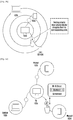
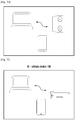
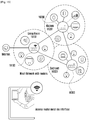
- FIG. 1 illustrates an example multi-device environment 100 providing a device connectivity management platform for managing inter-device connectivity among a plurality of secondary devices (for example, 102a to 102n) for services within the multi-device environment 100, wherein the device connectivity management platform is implemented in a primary device 104, according to exemplary embodiments as disclosed herein.
- the primary device 104 through the device connectivity management platform implemented on the primary device 104, can be configured to detect all the secondary devices within a pre-defined area based on one or more parameters and publish them on the UI provided for the device connectivity management platform.
- the detection of the secondary devices may be based on the one or more connectivity parameters.
- the detected secondary devices can include devices connected to a single or known Access Point (AP).
- AP Access Point
- the detected secondary devices can include devices registered with a same account or the like that may be discoverable through one or more available communication interfaces such as Bluetooth Low Energy (BLE), Wi-Fi, Wi-Fi HaLow, BLE, Oxygen MESH, or the like.
- BLE Bluetooth Low Energy
- Wi-Fi Wi-Fi
- Wi-Fi HaLow BLE
- Oxygen MESH Oxygen MESH
- the detected secondary devices may include devices that are not connected or not discoverable with reference to other secondary devices already detected.
- the unconnected or non-discoverable devices within the multi-device environment and lying within the pre-defined area may be known to detected secondary devices or may be relevant with respect to the primary device 104.
- non-compatible secondary devices can be displayed in the primary device 104 with a visual effect different from that of compatible secondary devices.
- non-compatible secondary devices may be displayed on the UI as grayed devices.
- the primary device does not have control authority to control the connection with other devices for some of the devices in the plurality of secondary devices.
- the control authority can be determined based on at least one of the attributes of a secondary device and the configuration of a user of the secondary device.
- the primary device only displays in the UI a secondary device with control authority, and can exclude secondary devices without control authority.
- the primary device identifies whether the primary device has an authority to control the connection with other secondary devices for each of the secondary devices.
- the primary device can identify a connection state between secondary devices based on a signal received from the secondary devices.
- the connection state between the secondary devices can be included in history information.
- history information may include information relating to a current connection and at least one previous connection with other secondary devices.
- the history information can include advertised packets output from the secondary devices and the primary device can identify the history information of each secondary device from the received advertised packets.
- the advertised packets output from the secondary devices can include simple information such as the device type (for example, mobile, TV, speaker, etc.), identity (for example, MAC, IP address, etc.), and so on, and in addition, can include whether the transmission of more data is available.
- the primary device can establish a connection with the secondary device and can request more data from the secondary device.
- more data can include the history information including current connection and at least one previous connection with other secondary devices, the possible connection media (for example, BLE, Wi-Fi, WFD), available service, connected subnet, and the like.
- the primary device may acquire the history information from at least one secondary device and identify the connection state between the detected secondary devices based on the history information.
- the primary device does not necessarily acquire the history information of all of the detected secondary devices. However, when the primary device can not identify a connection state for a particular secondary device among the detected secondary devices, the primary device may request the history information from another secondary device.
- the primary device 104 is a tablet owned by the user, while detected secondary devices (permanent devices including SD 102a through SD 102n) include a smart TV SD 102a, a laptop SD 102b, a mobile phone SD 102c, a slate SD 102d owned by the user and a robot cleaner SD 102n.
- detected secondary devices include a smart TV SD 102a, a laptop SD 102b, a mobile phone SD 102c, a slate SD 102d owned by the user and a robot cleaner SD 102n.
- other SDs that may be present in the area and detected by the primary device 104, including for example a mobile phone SD 102e belonging to a wife of the user, a washing machine SD 102f, a headphone SD 102g, a speaker SD 102h, and so on.
- the primary device 104 can be configured to identify one or more secondary devices selected by the user and connect them. Exemplary embodiments including interactive UIs for secondary device selection and connection are explained below in conjunction with FIG. 2A through FIG. 2C .
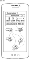
- FIG. 2A , FIG. 2B and Fig. 2C illustrate a UI of the primary device 104 enabling device connectivity management, according to exemplary embodiments as disclosed herein.
- FIG. 2A depicts the interactive UI, enabling connection among any two SDs from the plurality of SDs (102a through 102n) published on the UI on detection of a drag gesture from any one published SD to other SD.
- the interactive UI may display a connection state between the plurality of SDs (for example, active connection, inactive connection, connection procedure is pending, or error occurred).
- An input gesture (second input gesture such as drag) from one secondary device to other secondary device indicates to the primary device that the two SDs such as SD 102a (TV) and SD 102h (speaker) are selected and need to be connected.
- the drag gesture here can trigger the primary device 104 to initiate connection establishment process among the selected secondary devices (SD 102a and SD 102h) without the need for user to attend each secondary device individually.
- FIG. 2B illustrates a user selecting a secondary device of interest from the published secondary devices, wherein FIG. 2B depicts secondary devices which are registered as permanent devices.
- a gesture mechanism such as a tap gesture may be used to select the secondary device of interest, as depicted herein.
- a device focus mechanism such as camera assisted detection, may be used to select the secondary device of interest, which is explained further below in conjunction with FIG. 12A
- the primary device 104 can be configured to display all currently existing connections of the SD 102a, for example SD 102b, SD 102c and SD 102h.
- the other secondary devices that may be discovered by the primary device 104 but currently not connected with the secondary device of interest (SD 102a) can be displayed in a separate window, for example termed as discovered devices (here SD 102e, SD 102f, SD 102g ....and SD 102n).
- discovered devices here SD 102e, SD 102f, SD 102g ....and SD 102n.
- One or more of these discovered devices may be added to the SD 102a by tapping on the device of interest, displayed in the discovered devices window.
- SD 102e (wife's mobile phone) is added to the connected devices of the SD 102a.
- automatically a connection establishment is initiated between SD 102e and SD 102a on an appropriate communication interface identified by the primary device 104.
- the user may set the devices of friends or visitors as secondary devices that are registered as temporary devices for receiving services in the multi-device environment 100 for a preset time span.
- the example illustrated in FIG. 2C shows detected secondary devices that fall under temporary devices category in a separate window on the UI such as TD 202a and TD 202b.
- the user if intends, can tap on the TD 202a or 202b to add them and connect then to the SD 102a.
- the connection is established by identifying a suitable medium for communication. The connection establishment is explained below in conjunction with sequence diagram of FIG. 4 .
- FIG. 3A illustrates UI elements of the primary device 104 that represent device state with reference to connections among the plurality of secondary devices (102a to 102n), according to exemplary embodiments as disclosed herein.
- the processor of the primary device may cause the display to display a connection state between the plurality of secondary devices by using a plurality of connectors.
- the primary device 104 can be configured to display secondary devices connected to the secondary device of interest on the UI with connectors indicating device connection state.
- the secondary devices that are discovered but disconnected from the secondary device of interest are displayed in a separate window.
- a second input gesture connects at least one disconnected secondary device to the secondary device of interest.
- the UI elements (connectors) representing the device connection state or device connection status include a connector 302 indicating connection with user confirmation pending, a connector 304 indicating active connection, a connector 306 indicating an inactive connection, a connector 308 indicating an inactive connection with error, a connector 310 indicating a time bound connection for a temporary device, and the like.
- the connectors displayed convey the status of the connection to the user without need to check the settings for the secondary devices, whether permanent devices or temporary devices.
- a current device connection state between the selected secondary devices can be changed on detection of an input gesture on one or more connectors. Further, the changed device connection state can be updated, and the corresponding connector displayed on the UI can also be updated accordingly to display the updated device connection state.
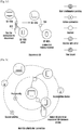
- FIG. 3B illustrates UI elements of the primary device 104, including a grid of concentric circles, provided to the user to assign a priority level (device priority status) to selected plurality of secondary devices, according to exemplary embodiments, not specifically claimed, as disclosed herein.
- the priority level can be a priority level when one secondary device is connected to other secondary devices.
- one secondary device can initially access a secondary device with a high priority level from among the searched secondary devices.
- secondary devices of the same type for example, earphone and speaker
- connection with the remaining secondary devices is disconnected.
- the priority level can be determined by at least one of hop count, ownership of the secondary device, connected AP, space currently located, accessibility (or control authority) of the primary device, number of previous connections, and the like.
- the primary device 104 can be configured to allow the user to assign the priority level to the selected secondary devices by placing each selected secondary device on a circle among the grid of concentric circles displayed on the UI. Each circle of the grid corresponds to a unique priority level.
- SD 102c placed on the highest proximity circle with respect to the SD 102a is assigned the highest priority, however currently has an inactive connection with SD 102a, while SD 102d has a second priority but has an active connection.
- the SD 102b is discovered but not connected to the SD 102a.
- FIG. 3C illustrates UI elements of the primary device, providing options to the user to select a communication interface for the selected connection between the selected secondary devices.
- the primary device may present an option for selecting at least one function relating to the connection state between the two secondary devices, in response to detecting an input gesture on a connector of the two secondary devices.
- the at least one function can include various functions related to the communication with the secondary device, such as the type of the accessed communication interface, channel, communication quality, access duration time, and the like.
- the primary device identifies at least one available service between the selected secondary devices.
- the available service can include available communication interfaces, type of service, type of network, and the like.
- the primary device displays in the UI a list of the at least one available service, and can establish a connection with the secondary devices through one of the services selected from the list.
- primary device can establish a connection of the selected secondary devices with one of the at least one available service.
- the primary device 104 can provide advanced interaction for granular control.
- a long press and scroll up/down on a connector can open and switch between different types of connections or communication interfaces between the connected secondary devices SD 102a and SD 102d.
- user can select a medium for communication interface from available communication interfaces between the SDs, such as Wi-Fi, Bluetooth or Screencast.
- FIGs. 3D and FIG. 3E illustrate device convergence provided by the primary device 104, according to exemplary embodiments as disclosed herein.
- FIG. 3D depicts a tap gesture performed by the user on the connection between the SD 102a and SD 102c displayed on the interactive UI.
- the user is able to control the connection state by simple gesture on the connector.
- a tap gesture 312 performed on the SD 102a can cause the connection between the SD 102a and the SD 102c to be disconnected.
- a tap gesture 314 on the connector can cause the connection to be established.
- the device connectivity management platform of the primary device 104 retains history information of all previous connections that may be used later for suggesting connection of interest to the user for similar intents.
- the connection state can be identified by the user based on the connectors displayed in accordance with connectors for connection state described in FIG. 3A .
- FIG. 3E depicts an exemplary embodiment, not specifically claimed, in which the user is allowed to override the device priority status, or priority level, defined by the grid when the user attempts to connect any two SDs.
- the user can drag and move the priority so that the SDs can be prioritized on-the-fly as desired by the user.
- FIG. 4 illustrates an example sequence diagram for discovery and connection establishment of the plurality of secondary devices from the primary device 104, according to exemplary embodiments.
- the primary device 104 may establish a connection between selected secondary devices.
- the primary device 104 may transmit a connection request message to each of selected two secondary devices.
- the two secondary devices can transmit the ACK message to the primary device 104.
- FIG. 4 depicts a user 400 utilizing the primary device 104 (tablet) that provides a device connectivity management platform for connectivity management among the plurality of secondary devices in the multi-device environment 100.
- the primary device 104 detects and publishes secondary devices present in the multi-device environment on the UI of the primary device 104 along with temporary devices, if any, that are registered with the primary device by the user.
- the secondary devices in the multi-device environment include the SD 102b (user's Laptop), the SD 102h (user's speaker), SD 102g (user's head phone).
- the temporary device TD 202a can be a visitor's mobile phone that may be included in the multi-device environment 100 and identified as valid device for a pre-defined time span set by the user 400.
- the user 400 launches the device connectivity management platform on the primary device 104 that initiates an automatic scan 404 to detect the devices in the multi-device environment 100 and publish the detected devices along with their current inter-device connection states.
- the primary device 104 receives advertised packets (packet 406, packet 408, and packet 410) over various communication interfaces from the SD 102b, the SD 102h, the SD 102g and the TD 202a.
- the primary device 104 receives UPnP packets over Wi-Fi from the SD 102b, over Bluetooth from SD 102h, over Bluetooth Low Energy (BLE) from the SD 102g and over Wi-Fi Direct from TD 202a.
- BLE Bluetooth Low Energy
- the primary device 104 performs a periodic scan 414 and stores the scan result in a cache.
- the scan result indicates the laptop SD 102b, speaker SD 102h, head phone SD 102g and visitor's mobile phone TD 202a as detected secondary devices along with their connection parameters such as capability, preference, priority, trust zone, and the like.
- the connection parameters can be included in the advertised packet transmitted from each secondary device, and can be transmitted to the primary device.
- the primary device 104 provides an update 416 to the UI and displays or publishes the updated information on the UI of the primary device with notification to the user 400.
- the UI displays classification of the devices as connected or disconnected with respect to other secondary devices published on the UI. For example, here present status display 418 indicates that speaker SD 102h already connected with laptop SD 102b with music on SD 102b being played in speaker SD 102h.
- the UI of the primary device 104 displays device status 420.
- FIG. 5 and FIG. 6 illustrate sequence diagrams describing switching of connections among the plurality of secondary devices from the UI of the primary device 104 for providing services in the multi-device environment 100, according to exemplary embodiments as disclosed herein.
- the current device status 502 in FIG. 5 may correspond to device status 420 where, the SD 102b (laptop) and the SD 102h (speaker) are connected.
- the user 400 intends to switch between devices in order to listen to the music played on laptop SD 102b on headphone SD 102g, the user performs a drag gesture from SD 102g to SD 102b.
- the gesture triggers an interface request 504 in the primary device 104, wherein the device connectivity management platform of the primary device 104 sends disconnect requests 506 and 508 to the SD 102b and the SD 102h.
- the disconnect request is over UPnP packet over Wi-Fi for SD 102b, and over Bluetooth packet for SD 102h.
- the primary device 104 receives ACK 512 and interface update ACK 514 from the SD 102b and SD 102h that are now disconnected. Further, the disconnected status is provided as an update 516 to the UI of the primary device 104.
- the primary device 104 selects a connection with a secondary device that has the same priority level as the selected secondary device (for example, user's laptop 102b) and the currently connected secondary device (for example, user's speaker 102h) or with the same type of secondary device (for example, user's head phone 102g), a request is made to automatically release the connection with the previously connected secondary device (for example, user's speaker 102h).
- a secondary device that has the same priority level as the selected secondary device (for example, user's laptop 102b) and the currently connected secondary device (for example, user's speaker 102h) or with the same type of secondary device (for example, user's head phone 102g)
- the primary device 104 sends connect requests 518 and 520 to the SD 102b over Wi-Fi and the SD 102g over BLE and then sends enable request 522 to enable configuration of the BLE communication interface on the SD 102b in order to connect over BLE with the SD 102g. Because the BLE interface for the head phone SD 102g is already enabled a discover procedure 524 and a connect procedure 526 is performed between the two secondary devices and SD 102b and the SD 102g to establish a connected state 528 over the BLE. The SD 102b sends ACK 530 and the SD 102g sends interface update ACK 532 to the primary device 104. In response, the primary device 104 provides an update 534 to the UI and displays updated device status 536, with the current status 538 indicating music played in headphone
- the current device status 602 in FIG. 6 may correspond to updated device status 536 where, the SD 102b (laptop) and the SD 102g (headphone) are connected.
- the user 400 intends to switch between devices to listen to the music played on visitor's mobile phone TD 202a, on the headphone SD 102g the user performs a drag gesture 602 from SD 102g to TD 202a.
- the gesture triggers an interface request 604 in the primary device 104, wherein the device connectivity management platform of the primary device 104 sends a disconnect requests 606 and 608 to the SD 102b and the SD 102g.
- the disconnect request is over UPnP packet over Wi-Fi for SD 102b while over BLE packet for SD 102g.
- the primary device 104 receives ACK 612 and interface update ACK 614 from the SD 102b and SD 102h that are now disconnected. Further, the disconnected status is provided as an update 616 by the primary device 104 on the UI.
- the primary device 104 sends connect requests 618 and 620 to the TD 202a over Wi-Fi Direct and the SD 102g (headphone) over BLE and then sends enable request 622 to enable configuration of BLE communication interface on the TD 202a in order to connect over BLE with the SD 102g. Because the BLE interface for the head phone SD 102g is already enabled a discover procedure 624, and a connect procedure 626 are performed between the two devices, and TD 202a and the SD 102g establish a connected status 628 over the BLE.
- the SD 102g sends ACK 630 and the TD 202a sends interface update ACK 632 to the primary device 104.
- the primary device 104 provides an update 634 to the UI and displays updated device status 636 with current status 638 indicating music from visitor's mobile played in headphone.
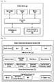
- FIG. 7A and 7B illustrate a plurality of components of the primary device 104 implementing the device connectivity management platform, according to the exemplary embodiments.
- the primary device 104 (electronic device) is illustrated in accordance with an exemplary embodiment of the present subject matter.
- the primary device 104 may include an input device 701, a processor 702, a display 703, an input/output (I/O) interface 704 (for example a configurable user interface), and a memory module 706.
- the display 703, for example, can include an LCD, an LED display, an OLED display, or an MEMS display, or an electronic paper display.
- the display 701 can display the user interface illustrated in FIGs. 2A to 2C .
- the input device 701, for example, can include a touch panel, a digital pen sensor, keys, or an ultrasonic input device.
- the input device 701 acquires the input generated in the user interface displayed in the display 703 and provides the input to the processor 702.
- the I/O interface 704 may include, for example, a web interface, and a graphical user interface (UI), a communication interface and the like.
- the communication interface allows the primary device 104 to communicate with other devices such plurality of secondary device 102a to 102n, a plurality of temporary devices such as TD 202a and TD 202b, also referred as plurality of electronic devices.
- the communication interface also allows communication with a server in a cloud network. Further, the communication interface may also enable communication through cellular networks, Wi-Fi networks, and device to device communication and the like.
- the memory module 706 maintains the data to be stored during the device connectivity management functions.
- the primary device 104 includes a device connectivity management platform 708 configured to manage inter-device connectivity among a plurality of secondary devices for services within the multi-device environment 100 as described in conjunction with FIG. 1 through FIG. 6 and FIG. 8 through FIG. 14 , not repeated for brevity.
- FIG. 7B illustrates a plurality of modular layers within the device connectivity management platform 708 including an application layer 710, a connectivity services layer 712 and a communication layer 714.
- the application layer includes a plurality of applications of the primary device 104.
- FIGs. 7C through 7E illustrate a method for discovering the plurality of secondary devices by the primary device, according to exemplary embodiments as disclosed herein.
- FIG. 7C is a flow diagram depicting a method 700c for discovering the plurality of secondary devices (for example herein, Device A corresponding to SD 102b and Device B corresponding to SD 102h) by a Device C (corresponding to primary device 104) in the multi-device environment 100.
- the Devices A, B, C advertise (operation 702c) over respective available media.
- Device connectivity management platform 708 of the primary device 104 launches (operation 704c) an interactive UI on the Device C
- the Device C scans (operation 706c) through available media such as BLE/WFD and receives advertisement from Device A and the Device B.
- the Device A is discovered with:
- the More Data may include history information relating to a current connection and at least one previous connection with other secondary devices.
- the method 700c enables the device connectivity management platform 708 to check whether More Data is available with Device A. Because, in the current example, More Data is available, the method 700c enables the device connectivity management platform 708 to connect (operation 710c) Device C with Device A and send a Discovery Request for More Data, wherein the More Data of Device A includes:
- More Data can be included in the advertised packets.
- primary device 104 can acquire the More Data (for example, history information) from the advertised packets, without establishing a connection with a secondary device.
- the Device C receives (operation 712c) a Discovery Response Packet from the Device A and adds (operation 714c) or connects the Device A to Device C as shown in FIG. 7D and displays it on the interactive UI as shown in the FIG. 7E .
- the various operations in the method 700c may be performed in the order presented, in a different order or simultaneously. Further, in some exemplary embodiments, some operations listed in FIG. 7C may be omitted.
- FIGs. 7F through FIG. 7H illustrate a method for connectivity services provided by the primary device to the discovered plurality of secondary devices, according to exemplary embodiments as disclosed herein.
- FIG. 7G is a flow diagram depicting a method 700g for connecting the plurality of secondary devices (for example herein, Device A corresponding to SD 102b and Device B corresponding to SD 102a) in the multi-device environment 100 on detection of a input gesture such as a drag gesture on the UI of Device C corresponding to primary device 104 as depicted in FIG. 7F .
- the method 700g allows the device interconnectivity management platform 708 of the primary device 104 (Device C) to provide (operation 702g) interaction gesture (such as drag gesture) to connect the Device A and Device B.
- the method 700g includes connecting (operation 704g) the Device C with Device A and Device B, using a medium selected based on parameters. Further, the method 700g includes deriving (operation 706g) possible services of the Device A and the Device B and publishing the derived services on the UI of the Device C. Further, the method 700g includes identifying (operation 708g) a service based on parameters to connect the Device A and the Device B (for example Miracast). Simultaneously, the method 700g includes listing (operation 710g) the available services between the Device A and the Device B (Miracast, WFD, Chromecast) and selecting (operation 712g) a required service (manual/auto) to connect the Device A and the Device B (for example WFD). Further, the method 700g includes interconnecting (operation 714g) Device A and Device B with the intended service and sending an ACK from the Device A and the Device B and disconnecting from the Device C (operation 716g) as shown in more detail in FIG. 7H .
- the various operations in the method 700g may be performed in the order presented, in a different order or simultaneously. Further, in some exemplary embodiments, some operations listed in FIG. 7G may be omitted.
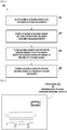
- FIG. 8 is a flow diagram illustrating a method 800 of providing the device connectivity management platform for managing device connectivity in the multi-device environment 100, according to exemplary embodiments.
- the method 800 includes allowing the device connectivity management platform 708 to detect the plurality of secondary devices (including for example secondary device SD 102a through SD 102n or temporary devices added by the user for pre-set time span) in an area (the pre-defined area defined by coverage of an AP, a femto-cell or the like) based on at least one parameter.
- the detection of the secondary devices may be based on the parameters such as connected devices such as devices connected to single or known Access Point (AP), a same account or the like, that may be discoverable through one or more available communication interfaces such as the BLE, Wi-Fi HaLow, BLE, Wi-Fi, Oxygen MESH, or the like.
- the method 800 includes allowing the device connectivity management platform 708 to publish the plurality of secondary devices on the UI provided for the device connectivity management platform 708 on the primary device 104.
- the method 800 includes allowing the device connectivity management platform 708 to identify the secondary devices selected from the published plurality of secondary devices, wherein the secondary devices are selected on detection of the input gesture (for example a first input gesture such as a tap gesture).
- the method 800 includes allowing the device connectivity management platform 708 to establish connections among the selected secondary devices on detection of the input gesture (for example a second input gesture such as a drag gesture).
- the primary device may disestablish the connection of the selected secondary devices.
- the connection establishment includes identifying a suitable medium from a plurality of media available for establishing the connection between the selected secondary devices. Further, requesting the selected secondary devices to enable the identified medium by configuring the medium at each selected secondary device end. Thereafter, initiating a discovery and connection establishment procedure between the selected secondary devices to establish the connection and displaying status of the connection among the selected secondary devices on the UI. An example of a connection establishment procedure is explained above in conjunction with sequence diagram of FIG. 4 .
- the method 800 includes allowing the device connectivity management platform 708 to assign the priority level to the selected secondary devices by placing each selected secondary device on a circle among concentric circles displayed on the UI, wherein each circle corresponds to a unique priority level.
- a priority assignment is explained above in conjunction with FIG. 3B .
- the method 800 includes allowing the device connectivity management platform 708 to enable access of the UI and the device connectivity management platform 708 through the cloud network to remotely select the secondary devices and establish the connection among the selected secondary devices.
- An example of remote access to the device management platform is explained below in conjunction with FIG. 11 .
- the method 800 includes allowing the device connectivity management platform 708 to identify a secondary device of interest among the plurality of secondary devices using a gesture, wherein secondary devices connected to the secondary device of interest are displayed on the UI with connectors indicating device connection state. Further, the secondary devices that are discovered but disconnected from the secondary device of interest are displayed in a separate window, wherein a second input gesture connects at least one disconnected secondary device to the secondary device of interest.
- the method 800 includes allowing the device connectivity management platform 708 to provide commands for execution of at least one action by the secondary device of interest through an interactive UI element (for example a microphone) of the device connectivity management platform 708.
- the interactive UI element is activated for the secondary device of interest on detecting a third input gesture on the UI, an example of which is explained below in conjunction with FIG. 12B .
- the method 800 includes allowing the device connectivity management platform 708 to display contents of the selected secondary devices on the UI of the primary device 104. Further, the content of a first secondary device is dragged and dropped on a second secondary device to initiate connection establishment and content transfer between the first secondary device and the second secondary device, an example of which is explained below in conjunction with FIG. 14
- the method 800 includes allowing the device connectivity management platform 708 to detect and add a secondary device of interest to the plurality of secondary devices detected by the device connectivity management platform 708 using the device focus mechanism, an example of which is explained below in conjunction with FIG. 12B .
- method 800 may be performed in the order presented, in a different order or simultaneously. Further, in some exemplary embodiments, some operations listed in FIG. 8 may be omitted.
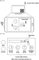
- FIG. 9 illustrates device connectivity management platform 708 implemented on primary device 104 when the primary device 104 is dedicated for device connectivity management functions, according to exemplary embodiments as disclosed herein.
- the dedicated primary device 104 can be a standalone accessory installed in the house, which can be accessed by one or more authorized users for managing device connectivity among the plurality of secondary devices in the multi-device environment at the user's home.
- Various exemplary embodiments of the present subject matter are not limited to the type illustrated in FIG. 9 .
- the device connectivity management platform 708 can be realized in various types of primary devices, including smartphones, tablet PCs, mobile telephones, video telephones, electronic book readers, desktop PCs, laptop PCs, netbook computers, work stations, servers, PDAs, PMPs (portable multimedia player), MP3 players, medical devices, cameras, and wearable devices.
- primary devices including smartphones, tablet PCs, mobile telephones, video telephones, electronic book readers, desktop PCs, laptop PCs, netbook computers, work stations, servers, PDAs, PMPs (portable multimedia player), MP3 players, medical devices, cameras, and wearable devices.
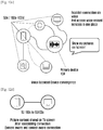
- FIG. 10A and FIG. 10B illustrate UI with the plurality of secondary devices displayed after classifying the secondary devices based on one or more criteria, according to exemplary embodiments as disclosed herein.
- FIG. 10A depicts detected permanent secondary devices displayed in a primary zone 1010 while detected temporary devices displayed in secondary zone 1020 on the UI of the primary device 104.
- a gesture such as tap gesture can select the temporary devices and shift them into primary zone 1010.
- FIG. 10B depicts a UI of the primary device 104 that can display relationship graphs of all users at home on the UI of the primary device 104.
- the figure depicts, for example, how User 1, User 2 and User 3 are connected to each other, wherein each relationship graph displayed on the primary device 104 represents a corresponding user.
- the relationship graph also depicts that the priority of other connected devices for every user is different. Hence, based on a priority of devices with respect to a particular user's device, the relationship graph can be represented in a different manner.
- FIG. 11 illustrates accessing of the device connectivity management platform of the primary device 104 through a cloud network 1104 for remotely managing connectivity among the plurality of secondary devices, according to exemplary embodiments.
- the user 400 when the user 400 is away from home (which can be multi-device environment 100) with the user's mobile phone SD 102c, the user is provided access to the primary device 104 and can effectively access the device connectivity management platform 708 to remotely manage device connectivity among one or more secondary devices at home.
- the user 400 may be busy on a video call with his wife, user 1102, corresponding to communication between SD 102c and SD 102e.
- the user 400 can do so by accessing the UI of the primary device 104 through the cloud network 1104.
- the user 400 can remotely perform device connectivity management without need for his wife, user 1102, to worry about operating the primary device 104.
- FIG. 12A illustrates detecting and adding a secondary device of interest to the plurality of secondary devices using a device focus mechanism, according to exemplary embodiments as disclosed herein.
- the SD 102a if not included in the list of detected SDs can be added using the device focus mechanism, wherein a camera interface on the primary device 104 can be focused on the secondary device of interest 102a.
- the primary device 104 can correctly identify the SD 102a as a smart TV based on a QR code or image recognition techniques.
- the secondary device of interest SD 102a can be connected to another secondary device SD 102c by an automatically triggered connection establishment, or using a drag gesture between SD 102a and SD 102e.
- FIG. 12B illustrates providing voice commands through a microphone of the primary device 104 for execution of at least one action by the secondary device of interest, according to exemplary embodiments.
- a third input gesture such as dragging of a UI element such as a microphone icon on the primary device 104 and dropping it onto the secondary device of interest, for example SD 102a, selected by the user enables providing instruction to SD 102a through voice commands from the microphone of the primary device 104 for management of device connectivity among the SDs.
- FIG. 12C and FIG. 12D illustrates exemplary embodiments in which the primary device provides voice extended device convergence for the interconnected plurality of secondary devices, according to exemplary embodiments.
- a voice input query is provided by the user in the primary device 104.
- the voice input query is interpreted by the device connectivity management platform 708 of the primary device 104 based on parameters, establishes corresponding connection, and processes voice input query on the SD 102c.
- the user is able to view contents of SD 102c (mobile phone) on the SD 102a (Smart TV).
- FIG. 13 illustrates an exemplary embodiment, not specifically claimed, including implementation of the device connectivity management platform 708 on a smart watch, which functions as the primary device 104, according to exemplary embodiments.
- the primary device 104 publishes all detected SDs.
- a drag gesture between an icon representing SD 102c (phone)and an icon representing SD 102a (TV) establishes connection between them.
- the primary device 104 displays all existing connections of the SD 102 (phone) with other published SDs.
- FIG. 14A illustrates an interactive UI of the primary device 104 and FIG. 14B illustrates operations performed by the device connectivity management platform 708 for enabling playing of audio/video content from one secondary device on a second secondary device with control commands performed at the UI of the primary device 104, according to exemplary embodiments.
- FIG. 14A depicts the UI of the primary device 104, publishing SD 102a, SD 102h, SD 102c, SD 102e on the UI. Current screen contents of SD 102c and SD 102e are also displayed.
- a user can perform a drag gesture dragging a content of interest, such as a video from SD 102c or SD 102e to another SD, for example SD 102a or SD 102h.
- this automatically establishes a connection between the selected SDs, initiates screening of contents from selected SD to other selected SDs, as explained below in an example method 1400 of the FIG. 14B .
- SDs are displayed (operation 1402) on the UI of the primary device, including SD 102a, SD 102c, SD 102e and SD 102h.
- the SD 102a smartt TV
- the SD 102c mobile phone
- the SD 102e wife's mobile phone
- the SD 102h the SD 102h
- the device management platform 708 of the primary device 104 can be configured to provide (operation 1406) interaction from the SD 102c to the SD 102a and from the SD 102e to the SD 102h by detecting dragging of content from the SD 102c and dropping on the SD 102a.
- the device management platform 708 of can be configured to identify (operation 1408) the SDs (SD 102a, SD 102c, SD 102e and SD 102h) and initiate (operation 1410) a connection request between the identified SDs (SD 102c to SD 102a, SD 102e to SD 102h). Further, the device management platform 708 can be configured to identify (operation 1412) the medium for the connection between the identified SDs (SD 102c to SD 102a, SD 102e to SD 102h) and ping (operation 1414) the identified SDs for enabling the medium.
- the device management platform 708 can be configured to establish (operation 1418) discovery and connection procedure between SD 102c and SD 102a, and between SD 102e and SD 102h. Further, the device management platform 708 can be configured to establish (operation 1420) connection between the SDs (SD 102c to SD 102a, and SD 102e to SD 102h) and transfer (operation 1422) selected video content (for example, a video clip) between SD 102c and SD 102a. and a selected audio content (for example, a song) between SD 102e and SD 102h.
- selected video content for example, a video clip
- FIG. 15 illustrates an exemplary embodiment not specifically claimed, in which the primary device 104 classifies an interconnected plurality of secondary devices into one or more subsets, and displays the subsets on the interactive UI.
- the primary device 104 displays the interconnection between the SDs, wherein the device connectivity management platform represents the SDs by classifying the connected SDs into one or more subsets such as a subset 1502, a subset 1504 and a subset 1506.
- the SDs belonging to a subset are related with a predefined parameter, for example herein, the subsets 1502, 1504 and 1506 display SDs classified based on spaces at home.
- subset 1502 displays SDs and their interconnection in a living room
- subset 1506 displays SDs and their interconnection in a bed room
- the device connectivity management platform 708 also displays a subset 1508 with current temporary devices in the multi-device environment 100. For example, when a friend is visiting the home, and when the friend's device is connected to Wi-Fi Access Point (AP) or other SDs, it can be displayed separately as the subset 1508. Further, any additional discovered devices can be displayed separately as subset 1510.
- AP Wi-Fi Access Point
- the UI also displays a voice icon, through which voice commands can be executed in the primary device 104 or SDs displayed on the UI.
- a voice control can be a command to initiate connection among SDs or command to execute operations in the connected SDs.
- the voice control can also be a query to fetch content from current / connected SDs.
- Table 1 below depicts a manner in which device connectivity management platform 708 can be configured to classify or form subset with 2 levels.
- Table 1 Parameters to define levels Hop/Link Ownership (Contact) Selection Channel-izing Device ⁇ >User Mapping AP Spaces At home Accessibil-ity Other-Prio rity Other - Parameters Level 1 Hop / Direct Link My device User moves and prioritize in UX (Order of devices) Listening to the port (Only listen to first device) User1 priority (mobile TV Tab) User2 priority (Washing machine Refrigera tor oven) Wifi AP Router Proximi ty of devices (Device priority at home) Home Proximity Most/Frequently/ Recently used devices Level 2 2 hop/ Indirect Link Third party (Friend's) device Block Secondary devices Wifi Share Hotspot Tether Extender Remote (cloud) No.
- the priority level can also be determined by number of previous connections, in addition to the above examples. For example, if secondary device 102a is more frequently connected to secondary device 102c rather than secondary device 102b, , the priority level of secondary device 102a regarding secondary device 102c is higher than the priority level regarding secondary device 102b. In addition, the priority level for the most recently connected secondary device can be higher than the above priority level. Furthermore, the priority level can be determined based on the type of the secondary device.
- the priority assigned to the SDs differs with each SD.
- Table 2 depicts capturing a priority of each SD with respect to each other SD.
- Table2 Current Device Level 1 Level 2 Level 3 Level 4 Smart phone Smart watch Fit Gears Tab Laptop Smart TV Speaker Player Home entertainment Washing Machine Refrigerator Oven and other home needs Sensor Priority
- FIG. 16 illustrates an example wherein the primary device 104 provides seamless continuity with a mesh network, according to exemplary embodiments.
- The. FIG. 16 depicts the interactive UI of the primary device 104 for enabling the user to quickly configure elements of the mesh network such as routers and their connections. Further, allows time bound and temporary connections among visible SDs and enables sharing access and connectivity to friends.
- the figure depicts multiple APs available at home. Multiple APs connected to multiple modem or single modem. As shown in FIG. 16 , AP 16100 is available in a living room 16101, AP 16200 is available in a kitchen 16201 and AP 16300 is available in a bedroom 16301 respectively, wherein some SDs are connected to each of the APs. Thus, based on the AP connection, the SDs can be classified and can be listed on the UI of the primary device 104.
- the user can move or drag the SDs from one AP to another AP. For example, dragging a first SD in a first AP to a second AP. Also, establishing connections among SDs connected to different APs are also possible.
- the exemplary embodiments disclosed herein can be implemented through at least one software program running on at least one hardware device and performing network management functions to control the network elements.
- the network elements shown in FIG. 1 through FIG. 16 include blocks which can be at least one of a hardware device, or a combination of hardware device and software module.
Claims (15)
- Procédé de gestion de connectivité de dispositif entre une pluralité de dispositifs secondaires (102a-n), par un dispositif primaire (104), le procédé comprenant :détecter tous les dispositifs secondaires (102a-n) dans une zone prédéfinie,acquérir des informations d'historique à partir d'au moins un dispositif secondaire de la pluralité de dispositifs secondaires (102a-n), les informations d'historique incluant des informations relatives à une connexion actuelle et au moins une connexion précédente parmi la pluralité de dispositifs secondaires (102a-n) ;identifier une pluralité d'états de connexion entre la pluralité de dispositifs secondaires (102a-n) sur la base des informations d'historique ;afficher la pluralité de dispositifs secondaires (102a-n) et la pluralité d'états de connexion entre la pluralité de dispositifs secondaires (102a-n) ; eten réponse à la réception d'une entrée pour deux dispositifs secondaires de la pluralité affichée de dispositifs secondaires (102a-n), identifier au moins un service disponible entre le deux dispositifs secondaires (102a-n), et changer un état de connexion ou une connectivité entre les deux dispositifs secondaires (102a-n) sur la base de l'au moins un service disponible.
- Procédé selon la revendication 1, où l'acquisition des informations d'historique comprend :recevoir des paquets annoncés à partir de l'au moins un dispositif secondaire périodiquement ;déterminer que des données supplémentaires sont disponibles à partir de l'au moins un dispositif secondaire ;établir une connexion entre le dispositif primaire (104) et l'au moins un dispositif secondaire ;recevoir les données supplémentaires à partir de l'au moins un dispositif secondaire ; etacquérir les informations d'historique à partir des données supplémentaires.
- Procédé selon la revendication 1, comprenant en outre :identifier si le dispositif primaire (104) a une autorité pour contrôler des connexions correspondant à chacun de la pluralité de dispositifs secondaires (102a-n),où l'affichage de la pluralité de dispositifs secondaires (102a-n) comprend l'affichage d'un dispositif secondaire sur lequel le dispositif primaire (104) a l'autorité.
- Procédé selon la revendication 1, comprenant en outre :identifier une pluralité de niveaux de priorité correspondant à la pluralité de dispositifs secondaires (102a-n) par rapport à l'au moins un dispositif secondaire,où l'affichage de la pluralité de dispositifs secondaires (102a-n) comprend la classification de la pluralité de dispositifs secondaires (102a-n) selon la pluralité de niveaux de priorité, et l'affichage de la pluralité de dispositifs secondaires (102a-n) selon la pluralité de niveaux de priorité.
- Procédé selon la revendication 4, où la pluralité de niveaux de priorité sont déterminés sur la base d'au moins l'un parmi le nombre de sauts, la propriété de la pluralité de dispositifs secondaires, des points d'accès correspondant à la pluralité de dispositifs secondaires, des positions de la pluralité de dispositifs secondaires (102a-n), l'accessibilité du dispositif primaire (104), et le nombre de connexions précédentes.
- Procédé selon la revendication 1, où le changement de l'état de connexion ou de la connectivité comprend :l'identification d'un service disponible à partir des deux dispositifs secondaires ; etle changement de l'état de connexion ou de la connectivité entre les deux dispositifs secondaires utilisant le service.
- Dispositif électronique (104) comprenant :une unité d'affichage (703) ;un émetteur-récepteur ; etun processeur (702) configuré pour gérer une connectivité de dispositif entre une pluralité de dispositifs secondaires (102a-n) :détecter tous les dispositifs secondaires (102a-n) dans une zone prédéfinie,acquérir des informations d'historique à partir d'au moins un dispositif secondaire de la pluralité de dispositifs secondaires (102a-n), les informations d'historique incluant des informations relatives à une connexion actuelle et au moins à une connexion précédente parmi la pluralité de dispositifs secondaires (102a-n) ;
identifier une pluralité d'états de connexion entre la pluralité de dispositifs secondaires (102a-n) sur la base des informations d'historique ;commander l'unité d'affichage (703) pour afficher la pluralité de dispositifs secondaires (102a-n) et la pluralité d'états de connexion entre les dispositifs secondaires ; eten réponse à la réception d'une entrée pour deux dispositifs secondaires de la pluralité affichée de dispositifs secondaires, commander pour identifier au moins un service disponible entre les deux dispositifs secondaires (102a-n), et changer un état de connexion ou une connectivité entre les deux dispositifs secondaires (102a-n) sur la base de l'au moins un service disponible. - Dispositif électronique (104) selon la revendication 7, où le processeur (702) est configuré en outre pour :recevoir des paquets annoncés à partir de l'au moins un dispositif secondaire périodiquement par l'émetteur-récepteur ;déterminer que des données supplémentaires sont disponibles à partir de l'au moins un dispositif secondaire ;établir une connexion entre le dispositif électronique (104) et l'au moins un dispositif secondaire ;recevoir les données supplémentaires à partir de l'au moins un dispositif secondaire par l'émetteur-récepteur ; etacquérir les informations d'historique à partir des données supplémentaires.
- Dispositif électronique (104) selon la revendication 7, où le processeur (702) est configuré en outre pour :identifier si le dispositif électronique (104) a une autorité pour contrôler des connexions correspondant à chacun de la pluralité de dispositifs secondaires (102a-n), etcommander l'unité d'affichage (703) pour afficher un dispositif secondaire sur lequel le dispositif électronique (104) a l'autorité.
- Dispositif électronique (104) selon la revendication 7, où le processeur (702) est configuré en outre pour :identifier une pluralité de niveaux de priorité correspondant à la pluralité de dispositifs secondaires (102a-n) par rapport à l'au moins un dispositif secondaire ;classifier la pluralité de dispositifs secondaires (102a-n) selon la pluralité de niveaux de priorité ; etcommander l'unité d'affichage (703) pour afficher la pluralité de dispositifs secondaires (102a-n) selon la pluralité de niveaux de priorité.
- Dispositif électronique (104) selon la revendication 10, où la pluralité de niveaux de priorité (102a-n) sont déterminés sur la base d'au moins l'un parmi le nombre de sauts, la propriété de la pluralité de dispositifs secondaires, les points d'accès correspondant à la pluralité de dispositifs secondaires, des positions de la pluralité de dispositifs secondaires, l'accessibilité du dispositif primaire et le nombre de connexions précédentes.
- Dispositif électronique (104) selon la revendication 10, où les deux dispositifs secondaires comprennent un premier dispositif secondaire et un deuxième dispositif secondaire, et
si le premier dispositif secondaire est connecté à un troisième dispositif secondaire de la pluralité de dispositifs secondaires et que le troisième dispositif secondaire a un même niveau de priorité que le deuxième dispositif secondaire, le processeur est configuré en outre pour :commander pour désactiver une connexion entre le premier dispositif secondaire et le troisième dispositif secondaire, etétablir la connexion entre les deux dispositifs secondaires. - Dispositif électronique (104) selon la revendication 7, où le processeur (702) est configuré en outre pour :identifier un service disponible à partir des deux dispositifs secondaires ; etchanger l'état de connexion ou la connectivité entre les deux dispositifs secondaires utilisant le service.
- Dispositif électronique (104) selon la revendication 7, où le processeur est configuré en outre pour :commander l'unité d'affichage (703) pour afficher une liste de services, la liste incluant le service ; etchanger la connexion entre les deux dispositifs secondaires sur la base du service sélectionné dans la liste.
- Dispositif électronique (104) selon la revendication 7, où le processeur est configuré en outre pour :
mettre à jour la pluralité affichée d'états de connexion lorsque l'état de connexion ou la connectivité des deux dispositifs secondaires est changé.
Applications Claiming Priority (2)
| Application Number | Priority Date | Filing Date | Title |
|---|---|---|---|
| IN201641014347 | 2016-04-25 | ||
| PCT/KR2017/004384 WO2017188704A2 (fr) | 2016-04-25 | 2017-04-25 | Procédés et systèmes de gestion d'une connectivité entre dispositifs |
Publications (3)
| Publication Number | Publication Date |
|---|---|
| EP3430824A2 EP3430824A2 (fr) | 2019-01-23 |
| EP3430824A4 EP3430824A4 (fr) | 2019-03-27 |
| EP3430824B1 true EP3430824B1 (fr) | 2021-02-24 |
Family
ID=60088273
Family Applications (1)
| Application Number | Title | Priority Date | Filing Date |
|---|---|---|---|
| EP17789888.9A Active EP3430824B1 (fr) | 2016-04-25 | 2017-04-25 | Procédés et systèmes de gestion d'une connectivité entre dispositifs |
Country Status (3)
| Country | Link |
|---|---|
| US (1) | US20170311368A1 (fr) |
| EP (1) | EP3430824B1 (fr) |
| WO (1) | WO2017188704A2 (fr) |
Families Citing this family (21)
| Publication number | Priority date | Publication date | Assignee | Title |
|---|---|---|---|---|
| US10608864B2 (en) * | 2011-08-24 | 2020-03-31 | Barco Limited | Method of establishing paid connection using screen mirroring application between multi-platforms |
| CN105160854B (zh) * | 2015-09-16 | 2019-01-11 | 小米科技有限责任公司 | 设备控制方法、装置和终端设备 |
| US10270875B1 (en) * | 2016-09-19 | 2019-04-23 | Amazon Technologies, Inc. | Dynamic grouping of device representations |
| US10270738B1 (en) * | 2016-09-19 | 2019-04-23 | Amazon Technologies, Inc. | Aggregated group state for a group of device representations |
| US10887174B2 (en) * | 2016-09-19 | 2021-01-05 | Amazon Technologies, Inc. | Group command management for device groups |
| US10929081B1 (en) * | 2017-06-06 | 2021-02-23 | United Services Automobile Association (Usaa) | Context management for multiple devices |
| US10986674B2 (en) * | 2017-06-07 | 2021-04-20 | Kubota Corporation | Communication processing system for working machine and communication processing method for working machine |
| US10531247B2 (en) | 2017-10-19 | 2020-01-07 | Libre Wireless Technologies Inc. | Internet-of-things devices and related methods for performing in-call interactions |
| US10887123B2 (en) * | 2017-10-19 | 2021-01-05 | Libre Wireless Technologies, Inc. | Multiprotocol audio/voice internet-of-things devices and related system |
| US11044764B2 (en) * | 2017-10-31 | 2021-06-22 | Ayla Networks, Inc. | Roaming of a device between stationary devices and mobile devices |
| US11297369B2 (en) * | 2018-03-30 | 2022-04-05 | Apple Inc. | Remotely controlling playback devices |
| US11026083B2 (en) * | 2018-09-27 | 2021-06-01 | Apple Inc. | Identification and user notification of mismatched devices |
| KR20200084587A (ko) * | 2019-01-03 | 2020-07-13 | 삼성전자주식회사 | 디스플레이 장치 및 그 제어 방법 |
| US11000759B2 (en) * | 2019-03-29 | 2021-05-11 | Valve Corporation | Game controller operable in bluetooth low energy (BLE) mode |
| US11445107B2 (en) * | 2019-08-08 | 2022-09-13 | Qorvo Us, Inc. | Supervised setup for control device with imager |
| US11868754B2 (en) | 2020-07-17 | 2024-01-09 | Sensia Llc | Systems and methods for edge device management |
| US20220018231A1 (en) | 2020-07-17 | 2022-01-20 | Sensia Llc | Systems and methods for a hydrocarbon configuration tool |
| CN114153531A (zh) * | 2020-08-18 | 2022-03-08 | 华为技术有限公司 | 管理物联网设备的方法和装置 |
| US20220182964A1 (en) * | 2020-12-09 | 2022-06-09 | Arris Enterprises Llc | Network presence detection |
| US11522927B2 (en) | 2020-12-15 | 2022-12-06 | Hio Inc. | Methods and systems for multimedia communication while accessing network resources |
| US11201900B1 (en) * | 2020-12-15 | 2021-12-14 | Hio Inc. | Methods and systems for multimedia communication while accessing network resources |
Family Cites Families (14)
| Publication number | Priority date | Publication date | Assignee | Title |
|---|---|---|---|---|
| US7937484B2 (en) * | 2004-07-09 | 2011-05-03 | Orb Networks, Inc. | System and method for remotely controlling network resources |
| JP4851354B2 (ja) * | 2007-02-01 | 2012-01-11 | アラクサラネットワークス株式会社 | ネットワーク設定情報管理システム |
| US7990897B2 (en) * | 2009-03-11 | 2011-08-02 | Sony Corporation | Method and apparatus for a wireless home mesh network with network topology visualizer |
| JP5163766B2 (ja) * | 2011-03-15 | 2013-03-13 | オムロン株式会社 | 設計支援システム |
| JP5782791B2 (ja) * | 2011-04-08 | 2015-09-24 | 株式会社バッファロー | 管理装置、管理方法、プログラムおよび記録媒体 |
| WO2012149724A1 (fr) * | 2011-09-05 | 2012-11-08 | 华为技术有限公司 | Procédé, dispositif et système de surveillance de liaison d'interconnexion de chemins rapide |
| EP2890138A1 (fr) * | 2013-12-30 | 2015-07-01 | Samsung Electronics Co., Ltd | Procédé de commande de dispositif d'affichage pour fournir un contenu et dispositif d'affichage mettant en oeuvre ce procédé |
| US9832804B2 (en) * | 2014-02-03 | 2017-11-28 | Sony Corporation | Device and method for wireless communication |
| KR20150092454A (ko) * | 2014-02-05 | 2015-08-13 | 삼성전자주식회사 | 디스플레이 장치, 디스플레이 장치의 제어 방법 및 컴퓨터 판독가능 기록매체 |
| CN106537848B (zh) * | 2014-04-28 | 2020-08-11 | 皇家飞利浦有限公司 | 无线通信系统 |
| TWI506528B (zh) * | 2014-05-26 | 2015-11-01 | Senao Networks Inc | Visual network management method |
| AU2015311069B2 (en) * | 2014-09-03 | 2019-12-12 | Electrolux Appliances Aktiebolag | Method for data communication with a domestic appliance by a mobile computer device, mobile computer device and domestic appliance |
| US10104218B2 (en) * | 2014-09-23 | 2018-10-16 | Lg Electronics Inc. | Mobile terminal and method for controlling same |
| US10401473B2 (en) * | 2015-07-30 | 2019-09-03 | Roku, Inc. | Mobile device based control device locator |
-
2017
- 2017-04-25 WO PCT/KR2017/004384 patent/WO2017188704A2/fr active Application Filing
- 2017-04-25 US US15/496,661 patent/US20170311368A1/en not_active Abandoned
- 2017-04-25 EP EP17789888.9A patent/EP3430824B1/fr active Active
Non-Patent Citations (1)
| Title |
|---|
| None * |
Also Published As
| Publication number | Publication date |
|---|---|
| WO2017188704A2 (fr) | 2017-11-02 |
| EP3430824A2 (fr) | 2019-01-23 |
| WO2017188704A3 (fr) | 2018-07-19 |
| EP3430824A4 (fr) | 2019-03-27 |
| US20170311368A1 (en) | 2017-10-26 |
Similar Documents
| Publication | Publication Date | Title |
|---|---|---|
| EP3430824B1 (fr) | Procédés et systèmes de gestion d'une connectivité entre dispositifs | |
| US11722528B2 (en) | Extending management control to IoT devices | |
| JP6394677B2 (ja) | 無線通信装置、通信システムおよび通信方法 | |
| EP2798779B1 (fr) | Transfert d'un évènement de communication | |
| WO2017097088A1 (fr) | Procédé et système de commande de projection à écrans-multiples, dispositif terminal, et support de stockage informatique | |
| EP4033773B1 (fr) | Procede de connexion pour dispositif de lecture multimedia, dispositif de lecture multimedia et terminal de commande | |
| JP6383109B2 (ja) | ネットワーク接続方法、ネットワーク接続機器、端末、通信機器、ネットワーク接続システム、プログラム及び記録媒体 | |
| JP5849173B2 (ja) | 装置とサービスの発見方法及び装置ミドルウェア | |
| GB2514856A (en) | Universal Environment Extender | |
| EP3515047B1 (fr) | Appareil de communication, appareil de capture d'images, procédé de commande et programme | |
| JP4649295B2 (ja) | 通信機器及び通信方法 | |
| WO2017031870A1 (fr) | Procédé de commande de groupement de dispositifs de lecture, et terminal d'utilisateur | |
| EP3398297B1 (fr) | Établissement d'une connexion entre deux dispositifs locaux connectés à différents réseaux | |
| US9888381B2 (en) | Method of controlling electronic device, electronic device, method of controlling access point and access point | |
| WO2023151423A1 (fr) | Procédé et appareil de connexion de dispositif, dispositif, et support de stockage | |
| US10028312B2 (en) | Communication apparatus, control method thereof, and storage medium | |
| CN106464759A (zh) | 一种局域网内消息发送方法、局域网网关和可穿戴设备 | |
| JP6001586B2 (ja) | ゲートウェイ装置におけるデバイス装置の設定方法、ゲートウェイ装置及びデバイス装置設定プログラム |
Legal Events
| Date | Code | Title | Description |
|---|---|---|---|
| STAA | Information on the status of an ep patent application or granted ep patent |
Free format text: STATUS: THE INTERNATIONAL PUBLICATION HAS BEEN MADE |
|
| PUAI | Public reference made under article 153(3) epc to a published international application that has entered the european phase |
Free format text: ORIGINAL CODE: 0009012 |
|
| STAA | Information on the status of an ep patent application or granted ep patent |
Free format text: STATUS: REQUEST FOR EXAMINATION WAS MADE |
|
| 17P | Request for examination filed |
Effective date: 20181018 |
|
| AK | Designated contracting states |
Kind code of ref document: A2 Designated state(s): AL AT BE BG CH CY CZ DE DK EE ES FI FR GB GR HR HU IE IS IT LI LT LU LV MC MK MT NL NO PL PT RO RS SE SI SK SM TR |
|
| AX | Request for extension of the european patent |
Extension state: BA ME |
|
| REG | Reference to a national code |
Ref country code: DE Ref legal event code: R079 Ref document number: 602017033383 Country of ref document: DE Free format text: PREVIOUS MAIN CLASS: H99Z9999999999 Ipc: H04L0012240000 |
|
| A4 | Supplementary search report drawn up and despatched |
Effective date: 20190221 |
|
| RIC1 | Information provided on ipc code assigned before grant |
Ipc: H04W 76/14 20180101ALI20190215BHEP Ipc: H04W 76/15 20180101ALI20190215BHEP Ipc: H04L 12/24 20060101AFI20190215BHEP Ipc: H04L 12/28 20060101ALI20190215BHEP Ipc: H04W 4/80 20180101ALI20190215BHEP |
|
| DAV | Request for validation of the european patent (deleted) | ||
| DAX | Request for extension of the european patent (deleted) | ||
| STAA | Information on the status of an ep patent application or granted ep patent |
Free format text: STATUS: EXAMINATION IS IN PROGRESS |
|
| 17Q | First examination report despatched |
Effective date: 20200422 |
|
| GRAP | Despatch of communication of intention to grant a patent |
Free format text: ORIGINAL CODE: EPIDOSNIGR1 |
|
| STAA | Information on the status of an ep patent application or granted ep patent |
Free format text: STATUS: GRANT OF PATENT IS INTENDED |
|
| INTG | Intention to grant announced |
Effective date: 20201118 |
|
| GRAS | Grant fee paid |
Free format text: ORIGINAL CODE: EPIDOSNIGR3 |
|
| GRAA | (expected) grant |
Free format text: ORIGINAL CODE: 0009210 |
|
| STAA | Information on the status of an ep patent application or granted ep patent |
Free format text: STATUS: THE PATENT HAS BEEN GRANTED |
|
| AK | Designated contracting states |
Kind code of ref document: B1 Designated state(s): AL AT BE BG CH CY CZ DE DK EE ES FI FR GB GR HR HU IE IS IT LI LT LU LV MC MK MT NL NO PL PT RO RS SE SI SK SM TR |
|
| REG | Reference to a national code |
Ref country code: CH Ref legal event code: EP |
|
| REG | Reference to a national code |
Ref country code: DE Ref legal event code: R096 Ref document number: 602017033383 Country of ref document: DE |
|
| REG | Reference to a national code |
Ref country code: AT Ref legal event code: REF Ref document number: 1365875 Country of ref document: AT Kind code of ref document: T Effective date: 20210315 |
|
| REG | Reference to a national code |
Ref country code: IE Ref legal event code: FG4D |
|
| REG | Reference to a national code |
Ref country code: LT Ref legal event code: MG9D |
|
| REG | Reference to a national code |
Ref country code: NL Ref legal event code: MP Effective date: 20210224 |
|
| PG25 | Lapsed in a contracting state [announced via postgrant information from national office to epo] |
Ref country code: PT Free format text: LAPSE BECAUSE OF FAILURE TO SUBMIT A TRANSLATION OF THE DESCRIPTION OR TO PAY THE FEE WITHIN THE PRESCRIBED TIME-LIMIT Effective date: 20210624 Ref country code: NO Free format text: LAPSE BECAUSE OF FAILURE TO SUBMIT A TRANSLATION OF THE DESCRIPTION OR TO PAY THE FEE WITHIN THE PRESCRIBED TIME-LIMIT Effective date: 20210524 Ref country code: HR Free format text: LAPSE BECAUSE OF FAILURE TO SUBMIT A TRANSLATION OF THE DESCRIPTION OR TO PAY THE FEE WITHIN THE PRESCRIBED TIME-LIMIT Effective date: 20210224 Ref country code: GR Free format text: LAPSE BECAUSE OF FAILURE TO SUBMIT A TRANSLATION OF THE DESCRIPTION OR TO PAY THE FEE WITHIN THE PRESCRIBED TIME-LIMIT Effective date: 20210525 Ref country code: FI Free format text: LAPSE BECAUSE OF FAILURE TO SUBMIT A TRANSLATION OF THE DESCRIPTION OR TO PAY THE FEE WITHIN THE PRESCRIBED TIME-LIMIT Effective date: 20210224 Ref country code: LT Free format text: LAPSE BECAUSE OF FAILURE TO SUBMIT A TRANSLATION OF THE DESCRIPTION OR TO PAY THE FEE WITHIN THE PRESCRIBED TIME-LIMIT Effective date: 20210224 Ref country code: BG Free format text: LAPSE BECAUSE OF FAILURE TO SUBMIT A TRANSLATION OF THE DESCRIPTION OR TO PAY THE FEE WITHIN THE PRESCRIBED TIME-LIMIT Effective date: 20210524 |
|
| PGFP | Annual fee paid to national office [announced via postgrant information from national office to epo] |
Ref country code: DE Payment date: 20210420 Year of fee payment: 5 |
|
| REG | Reference to a national code |
Ref country code: AT Ref legal event code: MK05 Ref document number: 1365875 Country of ref document: AT Kind code of ref document: T Effective date: 20210224 |
|
| PG25 | Lapsed in a contracting state [announced via postgrant information from national office to epo] |
Ref country code: PL Free format text: LAPSE BECAUSE OF FAILURE TO SUBMIT A TRANSLATION OF THE DESCRIPTION OR TO PAY THE FEE WITHIN THE PRESCRIBED TIME-LIMIT Effective date: 20210224 Ref country code: LV Free format text: LAPSE BECAUSE OF FAILURE TO SUBMIT A TRANSLATION OF THE DESCRIPTION OR TO PAY THE FEE WITHIN THE PRESCRIBED TIME-LIMIT Effective date: 20210224 Ref country code: RS Free format text: LAPSE BECAUSE OF FAILURE TO SUBMIT A TRANSLATION OF THE DESCRIPTION OR TO PAY THE FEE WITHIN THE PRESCRIBED TIME-LIMIT Effective date: 20210224 Ref country code: NL Free format text: LAPSE BECAUSE OF FAILURE TO SUBMIT A TRANSLATION OF THE DESCRIPTION OR TO PAY THE FEE WITHIN THE PRESCRIBED TIME-LIMIT Effective date: 20210224 Ref country code: SE Free format text: LAPSE BECAUSE OF FAILURE TO SUBMIT A TRANSLATION OF THE DESCRIPTION OR TO PAY THE FEE WITHIN THE PRESCRIBED TIME-LIMIT Effective date: 20210224 |
|
| PGFP | Annual fee paid to national office [announced via postgrant information from national office to epo] |
Ref country code: GB Payment date: 20210422 Year of fee payment: 5 |
|
| PG25 | Lapsed in a contracting state [announced via postgrant information from national office to epo] |
Ref country code: IS Free format text: LAPSE BECAUSE OF FAILURE TO SUBMIT A TRANSLATION OF THE DESCRIPTION OR TO PAY THE FEE WITHIN THE PRESCRIBED TIME-LIMIT Effective date: 20210624 |
|
| PG25 | Lapsed in a contracting state [announced via postgrant information from national office to epo] |
Ref country code: AT Free format text: LAPSE BECAUSE OF FAILURE TO SUBMIT A TRANSLATION OF THE DESCRIPTION OR TO PAY THE FEE WITHIN THE PRESCRIBED TIME-LIMIT Effective date: 20210224 Ref country code: SM Free format text: LAPSE BECAUSE OF FAILURE TO SUBMIT A TRANSLATION OF THE DESCRIPTION OR TO PAY THE FEE WITHIN THE PRESCRIBED TIME-LIMIT Effective date: 20210224 Ref country code: EE Free format text: LAPSE BECAUSE OF FAILURE TO SUBMIT A TRANSLATION OF THE DESCRIPTION OR TO PAY THE FEE WITHIN THE PRESCRIBED TIME-LIMIT Effective date: 20210224 Ref country code: CZ Free format text: LAPSE BECAUSE OF FAILURE TO SUBMIT A TRANSLATION OF THE DESCRIPTION OR TO PAY THE FEE WITHIN THE PRESCRIBED TIME-LIMIT Effective date: 20210224 |
|
| REG | Reference to a national code |
Ref country code: DE Ref legal event code: R097 Ref document number: 602017033383 Country of ref document: DE |
|
| REG | Reference to a national code |
Ref country code: DE Ref legal event code: R079 Ref document number: 602017033383 Country of ref document: DE Free format text: PREVIOUS MAIN CLASS: H04L0012240000 Ipc: H04L0041000000 |
|
| PG25 | Lapsed in a contracting state [announced via postgrant information from national office to epo] |
Ref country code: DK Free format text: LAPSE BECAUSE OF FAILURE TO SUBMIT A TRANSLATION OF THE DESCRIPTION OR TO PAY THE FEE WITHIN THE PRESCRIBED TIME-LIMIT Effective date: 20210224 Ref country code: SK Free format text: LAPSE BECAUSE OF FAILURE TO SUBMIT A TRANSLATION OF THE DESCRIPTION OR TO PAY THE FEE WITHIN THE PRESCRIBED TIME-LIMIT Effective date: 20210224 Ref country code: RO Free format text: LAPSE BECAUSE OF FAILURE TO SUBMIT A TRANSLATION OF THE DESCRIPTION OR TO PAY THE FEE WITHIN THE PRESCRIBED TIME-LIMIT Effective date: 20210224 Ref country code: MC Free format text: LAPSE BECAUSE OF FAILURE TO SUBMIT A TRANSLATION OF THE DESCRIPTION OR TO PAY THE FEE WITHIN THE PRESCRIBED TIME-LIMIT Effective date: 20210224 |
|
| PG25 | Lapsed in a contracting state [announced via postgrant information from national office to epo] |
Ref country code: LU Free format text: LAPSE BECAUSE OF NON-PAYMENT OF DUE FEES Effective date: 20210425 |
|
| PLBE | No opposition filed within time limit |
Free format text: ORIGINAL CODE: 0009261 |
|
| STAA | Information on the status of an ep patent application or granted ep patent |
Free format text: STATUS: NO OPPOSITION FILED WITHIN TIME LIMIT |
|
| REG | Reference to a national code |
Ref country code: BE Ref legal event code: MM Effective date: 20210430 |
|
| PG25 | Lapsed in a contracting state [announced via postgrant information from national office to epo] |
Ref country code: FR Free format text: LAPSE BECAUSE OF NON-PAYMENT OF DUE FEES Effective date: 20210430 Ref country code: ES Free format text: LAPSE BECAUSE OF FAILURE TO SUBMIT A TRANSLATION OF THE DESCRIPTION OR TO PAY THE FEE WITHIN THE PRESCRIBED TIME-LIMIT Effective date: 20210224 Ref country code: CH Free format text: LAPSE BECAUSE OF NON-PAYMENT OF DUE FEES Effective date: 20210430 Ref country code: AL Free format text: LAPSE BECAUSE OF FAILURE TO SUBMIT A TRANSLATION OF THE DESCRIPTION OR TO PAY THE FEE WITHIN THE PRESCRIBED TIME-LIMIT Effective date: 20210224 Ref country code: LI Free format text: LAPSE BECAUSE OF NON-PAYMENT OF DUE FEES Effective date: 20210430 |
|
| 26N | No opposition filed |
Effective date: 20211125 |
|
| PG25 | Lapsed in a contracting state [announced via postgrant information from national office to epo] |
Ref country code: SI Free format text: LAPSE BECAUSE OF FAILURE TO SUBMIT A TRANSLATION OF THE DESCRIPTION OR TO PAY THE FEE WITHIN THE PRESCRIBED TIME-LIMIT Effective date: 20210224 |
|
| PG25 | Lapsed in a contracting state [announced via postgrant information from national office to epo] |
Ref country code: IT Free format text: LAPSE BECAUSE OF FAILURE TO SUBMIT A TRANSLATION OF THE DESCRIPTION OR TO PAY THE FEE WITHIN THE PRESCRIBED TIME-LIMIT Effective date: 20210224 Ref country code: IE Free format text: LAPSE BECAUSE OF NON-PAYMENT OF DUE FEES Effective date: 20210425 |
|
| PG25 | Lapsed in a contracting state [announced via postgrant information from national office to epo] |
Ref country code: IS Free format text: LAPSE BECAUSE OF FAILURE TO SUBMIT A TRANSLATION OF THE DESCRIPTION OR TO PAY THE FEE WITHIN THE PRESCRIBED TIME-LIMIT Effective date: 20210624 |
|
| PG25 | Lapsed in a contracting state [announced via postgrant information from national office to epo] |
Ref country code: BE Free format text: LAPSE BECAUSE OF NON-PAYMENT OF DUE FEES Effective date: 20210430 |
|
| REG | Reference to a national code |
Ref country code: DE Ref legal event code: R119 Ref document number: 602017033383 Country of ref document: DE |
|
| GBPC | Gb: european patent ceased through non-payment of renewal fee |
Effective date: 20220425 |
|
| PG25 | Lapsed in a contracting state [announced via postgrant information from national office to epo] |
Ref country code: GB Free format text: LAPSE BECAUSE OF NON-PAYMENT OF DUE FEES Effective date: 20220425 Ref country code: DE Free format text: LAPSE BECAUSE OF NON-PAYMENT OF DUE FEES Effective date: 20221103 |
|
| PG25 | Lapsed in a contracting state [announced via postgrant information from national office to epo] |
Ref country code: CY Free format text: LAPSE BECAUSE OF FAILURE TO SUBMIT A TRANSLATION OF THE DESCRIPTION OR TO PAY THE FEE WITHIN THE PRESCRIBED TIME-LIMIT Effective date: 20210224 |
|
| PG25 | Lapsed in a contracting state [announced via postgrant information from national office to epo] |
Ref country code: HU Free format text: LAPSE BECAUSE OF FAILURE TO SUBMIT A TRANSLATION OF THE DESCRIPTION OR TO PAY THE FEE WITHIN THE PRESCRIBED TIME-LIMIT; INVALID AB INITIO Effective date: 20170425 |