EP3430668B1 - In-situ gravitational separation of electrolyte solutions in flow redox battery systems - Google Patents
In-situ gravitational separation of electrolyte solutions in flow redox battery systems Download PDFInfo
- Publication number
- EP3430668B1 EP3430668B1 EP17712677.8A EP17712677A EP3430668B1 EP 3430668 B1 EP3430668 B1 EP 3430668B1 EP 17712677 A EP17712677 A EP 17712677A EP 3430668 B1 EP3430668 B1 EP 3430668B1
- Authority
- EP
- European Patent Office
- Prior art keywords
- anolyte
- catholyte
- carrier slurry
- slurry
- active material
- Prior art date
- Legal status (The legal status is an assumption and is not a legal conclusion. Google has not performed a legal analysis and makes no representation as to the accuracy of the status listed.)
- Active
Links
- 239000008151 electrolyte solution Substances 0.000 title description 3
- 229940021013 electrolyte solution Drugs 0.000 title description 3
- 238000011065 in-situ storage Methods 0.000 title description 2
- 238000000926 separation method Methods 0.000 title description 2
- 239000002002 slurry Substances 0.000 claims description 222
- 239000011149 active material Substances 0.000 claims description 191
- 230000037361 pathway Effects 0.000 claims description 51
- 238000010248 power generation Methods 0.000 claims description 35
- 239000003014 ion exchange membrane Substances 0.000 claims description 24
- 239000002245 particle Substances 0.000 claims description 14
- LEONUFNNVUYDNQ-UHFFFAOYSA-N vanadium atom Chemical compound [V] LEONUFNNVUYDNQ-UHFFFAOYSA-N 0.000 claims description 9
- -1 ferrocyanide Chemical compound 0.000 claims description 8
- 229910052720 vanadium Inorganic materials 0.000 claims description 7
- 239000011701 zinc Substances 0.000 claims description 7
- GDTBXPJZTBHREO-UHFFFAOYSA-N bromine Substances BrBr GDTBXPJZTBHREO-UHFFFAOYSA-N 0.000 claims description 4
- WKBOTKDWSSQWDR-UHFFFAOYSA-N Bromine atom Chemical compound [Br] WKBOTKDWSSQWDR-UHFFFAOYSA-N 0.000 claims description 2
- 229910052684 Cerium Inorganic materials 0.000 claims description 2
- ZAMOUSCENKQFHK-UHFFFAOYSA-N Chlorine atom Chemical compound [Cl] ZAMOUSCENKQFHK-UHFFFAOYSA-N 0.000 claims description 2
- VYZAMTAEIAYCRO-UHFFFAOYSA-N Chromium Chemical compound [Cr] VYZAMTAEIAYCRO-UHFFFAOYSA-N 0.000 claims description 2
- NINIDFKCEFEMDL-UHFFFAOYSA-N Sulfur Chemical compound [S] NINIDFKCEFEMDL-UHFFFAOYSA-N 0.000 claims description 2
- HCHKCACWOHOZIP-UHFFFAOYSA-N Zinc Chemical compound [Zn] HCHKCACWOHOZIP-UHFFFAOYSA-N 0.000 claims description 2
- 229910052794 bromium Inorganic materials 0.000 claims description 2
- GWXLDORMOJMVQZ-UHFFFAOYSA-N cerium Chemical compound [Ce] GWXLDORMOJMVQZ-UHFFFAOYSA-N 0.000 claims description 2
- 239000000460 chlorine Substances 0.000 claims description 2
- 229910052801 chlorine Inorganic materials 0.000 claims description 2
- 229910052804 chromium Inorganic materials 0.000 claims description 2
- 239000011651 chromium Substances 0.000 claims description 2
- 239000004020 conductor Substances 0.000 claims description 2
- YAGKRVSRTSUGEY-UHFFFAOYSA-N ferricyanide Chemical compound [Fe+3].N#[C-].N#[C-].N#[C-].N#[C-].N#[C-].N#[C-] YAGKRVSRTSUGEY-UHFFFAOYSA-N 0.000 claims description 2
- WPBNNNQJVZRUHP-UHFFFAOYSA-L manganese(2+);methyl n-[[2-(methoxycarbonylcarbamothioylamino)phenyl]carbamothioyl]carbamate;n-[2-(sulfidocarbothioylamino)ethyl]carbamodithioate Chemical compound [Mn+2].[S-]C(=S)NCCNC([S-])=S.COC(=O)NC(=S)NC1=CC=CC=C1NC(=S)NC(=O)OC WPBNNNQJVZRUHP-UHFFFAOYSA-L 0.000 claims description 2
- 239000007787 solid Substances 0.000 claims description 2
- 239000011593 sulfur Substances 0.000 claims description 2
- 229910052717 sulfur Inorganic materials 0.000 claims description 2
- 229910052725 zinc Inorganic materials 0.000 claims description 2
- 239000000243 solution Substances 0.000 description 47
- 239000000376 reactant Substances 0.000 description 18
- 238000007599 discharging Methods 0.000 description 16
- 238000007254 oxidation reaction Methods 0.000 description 15
- 238000006722 reduction reaction Methods 0.000 description 15
- 239000012530 fluid Substances 0.000 description 14
- 230000003647 oxidation Effects 0.000 description 12
- 230000009467 reduction Effects 0.000 description 10
- MCMNRKCIXSYSNV-UHFFFAOYSA-N Zirconium dioxide Chemical compound O=[Zr]=O MCMNRKCIXSYSNV-UHFFFAOYSA-N 0.000 description 5
- 230000007423 decrease Effects 0.000 description 5
- 230000000694 effects Effects 0.000 description 5
- 229920002465 poly[5-(4-benzoylphenoxy)-2-hydroxybenzenesulfonic acid] polymer Polymers 0.000 description 5
- 229920000557 Nafion® Polymers 0.000 description 4
- 230000008859 change Effects 0.000 description 3
- 229910052751 metal Inorganic materials 0.000 description 3
- 239000002184 metal Substances 0.000 description 3
- 229910000478 neptunium(IV) oxide Inorganic materials 0.000 description 3
- 238000005086 pumping Methods 0.000 description 3
- 101150114085 soc-2 gene Proteins 0.000 description 3
- 239000004693 Polybenzimidazole Substances 0.000 description 2
- VYPSYNLAJGMNEJ-UHFFFAOYSA-N Silicium dioxide Chemical compound O=[Si]=O VYPSYNLAJGMNEJ-UHFFFAOYSA-N 0.000 description 2
- GWEVSGVZZGPLCZ-UHFFFAOYSA-N Titan oxide Chemical compound O=[Ti]=O GWEVSGVZZGPLCZ-UHFFFAOYSA-N 0.000 description 2
- 238000007667 floating Methods 0.000 description 2
- 238000007306 functionalization reaction Methods 0.000 description 2
- 230000007246 mechanism Effects 0.000 description 2
- 229910044991 metal oxide Inorganic materials 0.000 description 2
- 150000004706 metal oxides Chemical class 0.000 description 2
- 238000000034 method Methods 0.000 description 2
- VAOCPAMSLUNLGC-UHFFFAOYSA-N metronidazole Chemical compound CC1=NC=C([N+]([O-])=O)N1CCO VAOCPAMSLUNLGC-UHFFFAOYSA-N 0.000 description 2
- 229910003455 mixed metal oxide Inorganic materials 0.000 description 2
- 229920002480 polybenzimidazole Polymers 0.000 description 2
- 229920003934 Aciplex® Polymers 0.000 description 1
- KZBUYRJDOAKODT-UHFFFAOYSA-N Chlorine Chemical compound ClCl KZBUYRJDOAKODT-UHFFFAOYSA-N 0.000 description 1
- 229910017518 Cu Zn Inorganic materials 0.000 description 1
- 229910017752 Cu-Zn Inorganic materials 0.000 description 1
- 229910017943 Cu—Zn Inorganic materials 0.000 description 1
- 229920003935 Flemion® Polymers 0.000 description 1
- 229910052493 LiFePO4 Inorganic materials 0.000 description 1
- 229910052781 Neptunium Inorganic materials 0.000 description 1
- 239000002033 PVDF binder Substances 0.000 description 1
- 229920003295 Radel® Polymers 0.000 description 1
- 229910052770 Uranium Inorganic materials 0.000 description 1
- 229910009474 Y2O3—ZrO2 Inorganic materials 0.000 description 1
- MOPDXFDBEISTFG-UHFFFAOYSA-N [O--].[O--].[O--].[O--].[O--].[Np+5].[Np+5] Chemical compound [O--].[O--].[O--].[O--].[O--].[Np+5].[Np+5] MOPDXFDBEISTFG-UHFFFAOYSA-N 0.000 description 1
- WZECUPJJEIXUKY-UHFFFAOYSA-N [O-2].[O-2].[O-2].[U+6] Chemical compound [O-2].[O-2].[O-2].[U+6] WZECUPJJEIXUKY-UHFFFAOYSA-N 0.000 description 1
- PNEYBMLMFCGWSK-UHFFFAOYSA-N aluminium oxide Inorganic materials [O-2].[O-2].[O-2].[Al+3].[Al+3] PNEYBMLMFCGWSK-UHFFFAOYSA-N 0.000 description 1
- 239000012491 analyte Substances 0.000 description 1
- 230000004888 barrier function Effects 0.000 description 1
- 230000008901 benefit Effects 0.000 description 1
- CETPSERCERDGAM-UHFFFAOYSA-N ceric oxide Chemical compound O=[Ce]=O CETPSERCERDGAM-UHFFFAOYSA-N 0.000 description 1
- 229910000422 cerium(IV) oxide Inorganic materials 0.000 description 1
- 238000006243 chemical reaction Methods 0.000 description 1
- 239000003638 chemical reducing agent Substances 0.000 description 1
- TVZPLCNGKSPOJA-UHFFFAOYSA-N copper zinc Chemical compound [Cu].[Zn] TVZPLCNGKSPOJA-UHFFFAOYSA-N 0.000 description 1
- 239000003792 electrolyte Substances 0.000 description 1
- 238000005516 engineering process Methods 0.000 description 1
- 125000000524 functional group Chemical group 0.000 description 1
- 239000010954 inorganic particle Substances 0.000 description 1
- 150000002500 ions Chemical class 0.000 description 1
- 239000000463 material Substances 0.000 description 1
- 238000005259 measurement Methods 0.000 description 1
- 239000012528 membrane Substances 0.000 description 1
- LFNLGNPSGWYGGD-UHFFFAOYSA-N neptunium atom Chemical compound [Np] LFNLGNPSGWYGGD-UHFFFAOYSA-N 0.000 description 1
- 239000011146 organic particle Substances 0.000 description 1
- 239000007800 oxidant agent Substances 0.000 description 1
- 230000001590 oxidative effect Effects 0.000 description 1
- 230000008259 pathway mechanism Effects 0.000 description 1
- 229920002246 poly[2-(dimethylamino)ethyl methacrylate] polymer Polymers 0.000 description 1
- 229920000570 polyether Polymers 0.000 description 1
- 229920000642 polymer Polymers 0.000 description 1
- 229920001343 polytetrafluoroethylene Polymers 0.000 description 1
- 239000004810 polytetrafluoroethylene Substances 0.000 description 1
- 229920002981 polyvinylidene fluoride Polymers 0.000 description 1
- 238000006479 redox reaction Methods 0.000 description 1
- 230000002441 reversible effect Effects 0.000 description 1
- HBMJWWWQQXIZIP-UHFFFAOYSA-N silicon carbide Chemical compound [Si+]#[C-] HBMJWWWQQXIZIP-UHFFFAOYSA-N 0.000 description 1
- 229910010271 silicon carbide Inorganic materials 0.000 description 1
- 239000000377 silicon dioxide Substances 0.000 description 1
- 239000000126 substance Substances 0.000 description 1
- 229910000439 uranium oxide Inorganic materials 0.000 description 1
- JFALSRSLKYAFGM-UHFFFAOYSA-N uranium(0) Chemical compound [U] JFALSRSLKYAFGM-UHFFFAOYSA-N 0.000 description 1
Images


Classifications
-
- H—ELECTRICITY
- H01—ELECTRIC ELEMENTS
- H01M—PROCESSES OR MEANS, e.g. BATTERIES, FOR THE DIRECT CONVERSION OF CHEMICAL ENERGY INTO ELECTRICAL ENERGY
- H01M8/00—Fuel cells; Manufacture thereof
- H01M8/18—Regenerative fuel cells, e.g. redox flow batteries or secondary fuel cells
- H01M8/184—Regeneration by electrochemical means
- H01M8/188—Regeneration by electrochemical means by recharging of redox couples containing fluids; Redox flow type batteries
-
- H—ELECTRICITY
- H01—ELECTRIC ELEMENTS
- H01M—PROCESSES OR MEANS, e.g. BATTERIES, FOR THE DIRECT CONVERSION OF CHEMICAL ENERGY INTO ELECTRICAL ENERGY
- H01M8/00—Fuel cells; Manufacture thereof
- H01M8/04—Auxiliary arrangements, e.g. for control of pressure or for circulation of fluids
- H01M8/04276—Arrangements for managing the electrolyte stream, e.g. heat exchange
-
- H—ELECTRICITY
- H01—ELECTRIC ELEMENTS
- H01M—PROCESSES OR MEANS, e.g. BATTERIES, FOR THE DIRECT CONVERSION OF CHEMICAL ENERGY INTO ELECTRICAL ENERGY
- H01M8/00—Fuel cells; Manufacture thereof
- H01M8/20—Indirect fuel cells, e.g. fuel cells with redox couple being irreversible
-
- Y—GENERAL TAGGING OF NEW TECHNOLOGICAL DEVELOPMENTS; GENERAL TAGGING OF CROSS-SECTIONAL TECHNOLOGIES SPANNING OVER SEVERAL SECTIONS OF THE IPC; TECHNICAL SUBJECTS COVERED BY FORMER USPC CROSS-REFERENCE ART COLLECTIONS [XRACs] AND DIGESTS
- Y02—TECHNOLOGIES OR APPLICATIONS FOR MITIGATION OR ADAPTATION AGAINST CLIMATE CHANGE
- Y02E—REDUCTION OF GREENHOUSE GAS [GHG] EMISSIONS, RELATED TO ENERGY GENERATION, TRANSMISSION OR DISTRIBUTION
- Y02E60/00—Enabling technologies; Technologies with a potential or indirect contribution to GHG emissions mitigation
- Y02E60/30—Hydrogen technology
- Y02E60/50—Fuel cells
Definitions
- the present disclosure relates to flow redox battery systems. More specifically, the present disclosure introduces technology for flow redox battery systems that include electrolyte carrier slurries.
- Jia et al. published in Science Advances 2015, vol. 1 n. 10, page e1500886 discloses a redox flow battery comprising anode, cathode, Nafion®/PVDF membrane, anolyte tank and catholyte tank, wherein the anolyte tank comprises a TiO 2 slurry and the catholyte tank a LiFePO 4 slurry.
- a flow redox battery system includes an electrochemical cell, an anolyte tank, a catholyte tank , a first anolyte carrier slurry, a second anolyte carrier slurry, a first catholyte carrier slurry, a second catholyte carrier slurry, and a power generation circuit.
- the electrochemical cell includes an ion-exchange membrane positioned between and electrochemically engaged with an anode and a cathode.
- the power generation circuit is electrically coupled to the anode and the cathode.
- the anolyte tank comprises an anolyte upper end fluidly coupled to the anode and an anolyte lower end fluidly coupled to the anode.
- the catholyte tank includes a catholyte upper end fluidly coupled to the cathode and a catholyte lower end fluidly coupled to the cathode.
- the first anolyte carrier slurry includes a density that is less than a density of the second anolyte carrier slurry and an electronegativity that is different than an electronegativity of the second anolyte carrier slurry.
- the first catholyte carrier slurry includes a density that is less than a density of the second catholyte carrier slurry and an electronegativity that is different than an electronegativity of the second catholyte carrier slurry.
- a flow redox battery system includes an electrochemical cell, an anolyte tank, a catholyte tank, a first anolyte carrier slurry, a second anolyte carrier slurry, a first catholyte carrier slurry, a second catholyte carrier slurry, an anolyte solution, a catholyte solution, and a power generation circuit.
- the electrochemical cell includes an ion-exchange membrane positioned between and electrochemically engaged with an anode and a cathode.
- the power generation circuit is electrically coupled to the anode and the cathode.
- the anolyte tank includes an anolyte upper end fluidly coupled to the anode and an anolyte lower end fluidly coupled to the anode.
- the catholyte tank includes a catholyte upper end fluidly coupled to the cathode and a catholyte lower end fluidly coupled to the cathode.
- the anolyte solution is chemically engageable with the first anolyte carrier slurry and the second anolyte carrier slurry.
- the catholyte solution is chemically engageable with the first catholyte carrier slurry and the second catholyte carrier slurry.
- the first anolyte carrier slurry includes a density that is less than a density of the second anolyte carrier slurry and an electronegativity that is different than an electronegativity of the second anolyte carrier slurry.
- the first catholyte carrier slurry includes a density that is less than a density of the second catholyte carrier slurry and an electronegativity that is different than an electronegativity of the second catholyte carrier slurry.
- first and second anolyte carrier slurries and the first and second catholyte carrier slurries each comprise a plurality of slurry grains, each slurry grain comprising an inert core and one or more active particles chemically engaged with the inert core.
- a flow redox battery system includes an electrochemical cell, an anolyte tank, a catholyte tank, a first anolyte carrier slurry, a second anolyte carrier slurry, a first catholyte carrier slurry, a second catholyte carrier slurry, and a power generation circuit.
- the electrochemical cell includes an ion-exchange membrane positioned between and electrochemically engaged with an anode and a cathode.
- the power generation circuit is electrically coupled to the anode and the cathode.
- the anolyte tank includes an anolyte upper end fluidly coupled to the anode and an anolyte lower end fluidly coupled to the anode.
- the catholyte tank includes a catholyte upper end fluidly coupled to the cathode and a catholyte lower end fluidly coupled to the cathode.
- the first anolyte carrier slurry includes a density that is less than a density of the second anolyte carrier slurry such that the first anolyte carrier slurry floats above the second anolyte carrier slurry when the first and second anolyte carrier slurries are housed within the anolyte tank.
- the first anolyte carrier slurry includes an electronegativity that is greater than an electronegativity of the second anolyte carrier slurry such that the first anolyte carrier slurry electrochemically attracts a discharged anolyte active material and the second anolyte carrier slurry electrochemically attracts a charged anolyte active material.
- the first catholyte carrier slurry includes a density that is less than a density of the second catholyte carrier slurry such that the first catholyte carrier slurry floats above the second catholyte carrier slurry when the first and second catholyte carrier slurries are housed within the catholyte tank.
- the first catholyte carrier slurry includes an electronegativity that is less than the electronegativity of the second catholyte carrier slurry such that the first catholyte carrier slurry electrochemically attracts a discharged catholyte and the second catholyte carrier slurry electrochemically attracts a charged catholyte active material.
- Fig. 1 is a schematic illustration of a flow reduction/oxidation (redox) battery system 100.
- the flow redox battery system 100 comprises an electrochemical cell 110, an anolyte tank 130, a catholyte tank 140, and a power generation circuit 170.
- the electrochemical cell 110 is fluidly coupled to the anolyte tank 130 and the catholyte tank 140 and is electrically coupled to the power generation circuit 170.
- the flow redox battery system 100 comprises a first anolyte carrier slurry 150 and a second anolyte carrier slurry 152, which may each be housed within the anolyte tank 130 and may each flow between the anolyte tank 130 and the electrochemical cell 110.
- the flow redox battery system 100 also comprises a first catholyte carrier slurry 154 and a second catholyte carrier slurry 156, which may each be housed within the catholyte tank 140 and may each flow between the catholyte tank 140 and the electrochemical cell 110. Moreover, the flow redox battery system 100 includes electrolyte solutions such as an anolyte solution and a catholyte solution.
- the anolyte solution may be housed within the anolyte tank 130 and may flow between the anolyte tank 130 and the electrochemical cell 110.
- the anolyte solution may comprise a plurality of charged anolyte active materials, a plurality of discharged anolyte active materials, or combinations thereof and is compositionally configured to oxidize at the electrochemical cell 110 during a discharging operation of the flow redox battery system 100 and reduce at the electrochemical cell 110 during a charging operation of the flow redox battery system 100.
- active material refers to a chemical component such as an atom, ion, molecule, or the like, that is compositionally configured to change oxidation states when undergoing a redox reaction.
- the active materials of the anolyte solution may comprise vanadium, chromium, zinc, sulfur, neptunium, uranium, or a combination thereof.
- each of the plurality of charged anolyte active materials comprise a lower positive charge and a lower oxidation state than each of the plurality of discharged anolyte active materials.
- the catholyte solution may be housed within the catholyte tank 140 and may flow between the catholyte tank 140 and the electrochemical cell 110.
- the catholyte solution may comprise a plurality of charged catholyte active materials, a plurality of discharged catholyte active materials, or combinations thereof and is compositionally configured to reduce at the electrochemical cell 110 during the discharging operation and oxidize at the electrochemical cell 100 during the charging operation.
- Each of the plurality of charged catholyte active materials comprise a higher positive charge and a higher oxidation state than each of the plurality of discharged catholyte active materials.
- the active materials of the catholyte solution may comprise vanadium, bromine, cerium, chlorine, ferricyanide, ferrocyanide, manganese, neptunium oxide, uranium oxide, or a combination thereof.
- anolyte solution and catholyte solution may each comprise any active material having redox pairs which exhibit different standard reduction potentials. Further, the anolyte solution may comprise an active material with a lower standard reduction than the active material of the catholyte solution.
- the table below depicts a non-exhaustive list of active material redox pairs that may be used as the catholyte solution and the analyte solution.
- Catholyte Solution Active Materials Anolyte Solution Active Materials Anolyte Solution Active Materials Cr 3+ /Cr 2+ Fe 3+ /F 2+ V 3+ /N 2+ V 5+ /V 4+ V 3+ /V 2+ Br 2 /Br- V 3+ /V 2+ Fe 3+ /F 2+ V 3+ /V 2+ Ce 4+ /Ce 3+ Zn 2+ /Zn Cl-/Cl 2 Zn 2+ /Zn Br-/Br 2 Zn 2+ /Zn Ce 4+ /Ce 3+ Zn 2+ /Zn V 5+ /V 4+ Zn 2+ /Zn [Fe(CN) 6 ] 4- /[Fe(CN) 6 ] 3- V 3+ /V 2+ Ce 4+ /Ce 3+ V 3+ /V 2+ Mn 3+ /Mn 2+ S 2 2- /S 4 2- Br - /Br 3 - Np 4+
- the electrochemical cell 110 comprises an ion-exchange membrane 120 positioned between and electrochemically engaged with an anode 112 and a cathode 122.
- the anode 112 includes an anode conductive portion 116 electrically coupled to the power generation circuit 170 such that electrons may flow between the anode 112 and the power generation circuit 170.
- the anode 112 also includes an anolyte receiving portion 114 fluidly coupled to the anolyte tank 130 such that the first and second anolyte carrier slurries 150, 152 and the anolyte solution may flow between the anolyte tank 130 and the anolyte receiving portion 114 of the anode 112.
- the anolyte solution may electrochemically contact the ion-exchange membrane 120 and the anode conductive portion 116.
- the cathode 122 includes a cathode conductive portion 126 electrically coupled to the power generation circuit 170 such that electrons may flow between the cathode 122 and the power generation circuit 170.
- the cathode 122 also includes a catholyte receiving portion 124 fluidly coupled to the catholyte tank 140 such that the first and second catholyte carrier slurries 156, 158 and the catholyte solution may flow between the catholyte tank 140 and the catholyte receiving portion 124 of the cathode 122.
- the catholyte solution may electrochemically contact the ion-exchange membrane 120 and the cathode conductive portion 126.
- the ion-exchange membrane 120 may comprise a solid state proton conducting material, for example, Nafion®, Nafion® 117, Flemion®, Fumapem®, Aciplex®, Dow® materials, Selemion®, TPS®, Gore® L01854, Gore® M04494, ABT3, ABT4, SZ, Hipore®, SPEEK, Nafion®/SPEEK, PSSS, SPTK, Radel®, PVDF-PSSA, ETFE-PDMAEMA, SPEEK/TPA, TPA/PP, SPEEK/PTFE, SPEEK/PFSA, PBI, PSf-ABIm, polybenzimidazole, polyether polymer, or the like.
- a solid state proton conducting material for example, Nafion®, Nafion® 117, Flemion®, Fumapem®, Aciplex®, Dow® materials, Selemion®, TPS®, Gore® L01854, Go
- the ion-exchange membrane 120 is positioned within the electrochemical cell 110 and may provide a physical barrier between the anolyte receiving portion 114 of the anode 112 and the catholyte receiving portion 124 of the cathode 122. Further, the ion-exchange membrane 120 is structurally configured to provide a proton pathway 108 between the anode 112 and the cathode 122 such that protons may flow therebetween to facilitate oxidation and reduction reactions within the anode 112 and the cathode 122 during the discharging operation and the charging operation of the flow redox battery system 100.
- the proton pathway 108 of the ion-exchange membrane 120 may close a circuit between the anode 112, the power generation circuit 170, and the cathode 122 such that oxidation and reduction reactions may generate electron flow between the anode 112 and the cathode 122 and through the power generation circuit 170, and may generate proton flow between the anode 112 and the cathode 122 and through the ion-exchange membrane 120.
- protons may traverse the proton pathway 108 provided by the ion-exchange membrane 120 in a proton discharging flow direction 104 from the cathode 122 to the anode 112 and during the charging operation, protons may traverse the proton pathway 108 of the ion-exchange membrane 120 in a proton charging flow direction 105 from the anode 112 to the cathode 122.
- the power generation circuit 170 comprises a power generation unit 174.
- the circuit pathway 172 is electrically coupled to the anode 112, the power generation unit 174 and the cathode 122.
- the circuit pathway 172 may extend between and electrically couple the anode 112 and the power generation unit 174 and the circuit pathway may extend between and electrically coupled the cathode 122 and the power generation unit 174.
- the power generation unit 174 may comprise a power source and an electrical load.
- the power generation unit 174 is structurally configured to receive current generated by electrons output by the anode 112 and, upon receiving current, generate power.
- the power generation unit 174 is also structurally configured to output current receivable by the anode 112 to charge the anolyte solution and the catholyte solution.
- the first anolyte carrier slurry 150 and the second anolyte carrier slurry 152 are each compositionally configured to attract active materials of an anolyte solution and chemically engage the active materials of the anolyte solution.
- the first anolyte carrier slurry 150 may be compositionally configured to attract and chemically engage one of the plurality of discharged or charged anolyte active materials
- the second anolyte carrier slurry 152 may be compositionally configured to attract and chemically engage the other of the plurality of discharged or charged anolyte active materials, for example, to separate the pluralities of charged and discharged anolyte active materials within the anolyte tank 130.
- first catholyte carrier slurry 154 and the second catholyte carrier slurry 156 are each compositionally configured to attract active materials of the catholyte solution and chemically engage the catholyte solution.
- first catholyte carrier slurry 154 may be compositionally configured to attract and chemically engage one of the plurality of discharged or charged catholyte active materials
- the second catholyte carrier slurry 156 may be compositionally configured to attract and chemically engage the other of the plurality of discharged or charged catholyte active materials, for example, to separate the pluralities of charged and discharged catholyte active materials.
- the first and second anolyte carrier slurries 150, 152 and the first and second catholyte carrier slurries 154, 156 of Fig. 1 may each comprise a plurality of slurry grains 160.
- Each slurry grain 160 includes an inert core 162 and one or more active particles 166 chemically engaged with the inert core 162.
- the inert core 162 may comprise an organic particle, an inorganic particle, or a combination thereof.
- the inert core 162 may comprise alumina, silica, silicon carbide, zirconia, ceria, a polymer particle, a single metal oxide, a mixed metal oxide, or a combination thereof.
- the inert core 162 of the slurry grains 160 of the first anolyte carrier slurry 150 may have a lower density than the inert core 162 of the slurry grains 160 of the second anolyte carrier slurry 152, such that the first anolyte carrier slurry 150 may float above the second anolyte carrier slurry 152.
- the inert core 162 of the slurry grains 160 of the first catholyte carrier slurry 154 may have a lower density than the inert core 162 of the slurry grains 160 of the second catholyte carrier slurry 156, such that the first catholyte carrier slurry 154 may float above the second catholyte carrier slurry 156.
- the slurry grains 160 further comprise one or more functionalized surface regions 164 positioned along the surface of the inert core 162 and one or more active particles 166 chemically engaged with the inert core 162 at the one or more functionalized surface regions 164.
- the functionalized surface regions 164 may be chemically configured to bond with one or more functional groups of the active particles 166, for example, using a functionalization method such as a chemo-functionalization method.
- the one or more active particles 166 may comprise a metal, for example, Cu, a metal oxide, for example, ZrO 2 , a mixed metal, for example, Cu-Zn, a mixed metal oxide, for example, .
- the one or more active particles 166 are compositionally configured to attract and chemically engage the discharged or charged catholyte active materials and the discharged or charged anolyte active materials.
- the one or more active particles 166 of the first anolyte carrier slurry 150 may comprise a different electronegativity the one or more active particles 166 of the second carrier slurry 152 and the one or more active particles 166 of the first catholyte carrier slurry 154 may comprise a different electronegativity than the one or more active particles 166 the second catholyte carrier slurry 156.
- the first and second anolyte carrier slurries 150, 152 are immiscible such that the first and second anolyte carrier slurries 150, 152 separate when housed within anolyte tank 130.
- the first anolyte carrier slurry 150 comprises a density that is less than a density of the second anolyte carrier slurry 152 such that the first anolyte carrier slurry 150 floats above the second anolyte carrier slurry 152 when the first and second anolyte carrier slurries 150, 152 are housed within the anolyte tank 130.
- the first anolyte carrier slurry 150 comprises an electronegativity that is different than an electronegativity of the second anolyte carrier slurry 152 such that one of the first and second anolyte carrier slurries 150, 152 electrochemically attract the charged anolyte active materials of the anolyte solution and the other of the first and second anolyte carrier slurries 150, 152 electrochemically attracts the discharged anolyte active materials of the anolyte solution.
- the electronegativity of the first anolyte carrier slurry 150 may be greater than the electronegativity of the second anolyte carrier slurry 152 such that the first anolyte carrier slurry 150 electrochemically attracts the plurality of discharged anolyte active materials, the second anolyte carrier slurry 152 electrochemically attracts the plurality of charged anolyte active materials, and the plurality of discharged anolyte active materials float above the plurality of charged anolyte active materials.
- the electronegativity of the first anolyte carrier slurry 150 may be less than the electronegativity of the second anolyte carrier slurry 152 such that the first anolyte carrier slurry 150 electrochemically attracts the plurality of charged anolyte active materials, the second anolyte carrier slurry 152 electrochemically attracts the plurality of discharged anolyte active materials, and the plurality of charged anolyte active materials float above the plurality of discharged anolyte active materials.
- the first and second catholyte carrier slurries 154, 156 are immiscible such that the first and second catholyte carrier slurries 154, 156 separate when housed within catholyte tank 140.
- the first catholyte carrier slurry 154 comprises a density that is less than a density of the second catholyte carrier slurry 156 such that the first catholyte carrier slurry 154 floats above the second catholyte carrier slurry 156 when the first and second catholyte carrier slurries 154, 156 are housed within the catholyte tank 140.
- the first catholyte carrier slurry 154 comprises an electronegativity that is different than an electronegativity of the second catholyte carrier slurry 156 such that one of the first and second catholyte carrier slurries 154, 156 electrochemically attract the charged catholyte active materials of the catholyte solution and the other of the first and second catholyte carrier slurries 154, 156 electrochemically attracts the discharged catholyte active materials of the catholyte solution.
- the electronegativity of the first catholyte carrier slurry 154 may be greater than the electronegativity of the second catholyte carrier slurry 156 such that the first catholyte carrier slurry 154 electrochemically attracts the plurality of charged catholyte active materials, the second catholyte carrier slurry 156 electrochemically attracts the plurality of discharged catholyte, and the plurality of charged catholyte active materials float above the plurality of discharged catholyte active materials.
- the electronegativity of the first catholyte carrier slurry 154 may be less than the electronegativity of the second catholyte carrier slurry 156 such that the first catholyte carrier slurry 154 electrochemically attracts the plurality of discharged catholyte active materials, the second catholyte carrier slurry 156 electrochemically attracts the plurality of charged catholyte active materials, and the plurality of discharged catholyte active materials float above the plurality of charged catholyte active materials.
- the anolyte tank 130 comprises an anolyte upper end 132 and an anolyte lower end 134 each fluidly coupled to the anode 112.
- a low density anolyte pathway 136 extends between and fluidly couples the anolyte upper end 132 of the anolyte tank 130 and the anode 112 and a high density anolyte pathway 138 extends between and fluidly couples the anolyte lower end 134 of the anolyte tank 130 and the anode 112.
- the low density anolyte pathway 136 and the high density anolyte pathway 138 each comprise a tube, pipe or other fluid pathway mechanism.
- An anolyte pump 139 is fluidly coupled to one of the low density anolyte pathway 136 or the high density anolyte pathway 138.
- the anolyte pump 139 comprises any fluid pumping mechanism and is structurally configured to generate fluid flow between the anolyte tank 130 and the anode 112. While the anolyte pump 139 depicted in Fig. 1 is fluidly coupled to the low density anolyte pathway 136, the anolyte pump 139 may be fluidly coupled to the high density anolyte pathway 138 or multiple anolyte pumps 139 may be fluidly coupled to one or both of the low density anolyte pathway 136 or the high density anolyte pathway 138.
- the catholyte tank 140 comprises a catholyte upper end 142 and a catholyte lower end 144 each fluidly coupled to the cathode 122.
- a low density catholyte pathway 146 extends between and fluidly couples the catholyte upper end 142 of the catholyte tank 140 and the cathode 122 and a high density catholyte pathway 148 extends between and fluidly couples the catholyte lower end 144 of the catholyte tank 140 and the cathode 122.
- the low density catholyte pathway 146 and the high density catholyte pathway 148 may comprise a tube, or any other fluid pathway.
- a catholyte pump 149 fluidly coupled to one of the low density catholyte pathway 146 or the high density catholyte pathway 148.
- the catholyte pump 149 comprises any fluid pumping mechanism and is structurally configured to generate fluid flow between the catholyte tank 140 and the cathode 122. While the catholyte pump 149 depicted in Fig. 1 is fluidly coupled to the low density catholyte pathway 146, the catholyte pump 149 may be fluidly coupled to the high density catholyte pathway 148 or multiple catholyte pumps 149 may be coupled to one or both of the low density catholyte pathway 146 or the high density catholyte pathway 148.
- the anode 112 may receive a charged anolyte active material chemically engaged with the first or second anolyte carrier slurry 150, 152.
- the anode 112 may also receive a proton output by the cathode 122 from the proton pathway 108 formed by the ion-exchange membrane 120 to oxidize the charged anolyte active material and chemically separate the oxidized active material from the first or second anolyte carrier slurry 150, 152 at the anode 112.
- the charged anolyte active material When oxidized, the charged anolyte active material outputs an electron receivable by the anode conductive portion 116 such that the electrons flow in an electron discharging direction 106 along the circuit pathway 172 to the power generation circuit 170. Moreover, after oxidation, the previously charged anolyte active material comprises a discharged anolyte active material and flows from the anode 112 back to the anolyte tank 130.
- the anolyte pump 139 may generate fluid flow in a first flow direction 102 from the anolyte lower end 134 to the anode 112 and from the anode 112 to the anolyte upper end 132.
- the charged anolyte active materials chemically engaged with the higher density second anolyte carrier slurry 152 may flow along the high density anolyte pathway 138 in the first flow direction 102 from the anolyte lower end 134 to the anode 112 such that anode 112 fills with charged anolyte active materials compositionally configured to undergo oxidation and discharge.
- the now discharged anolyte active materials may flow along the low density anolyte pathway 136 in the first flow direction 102 from the anode 112 to the anolyte upper end 132 such that the first anolyte carrier slurry 150 floating above the second anolyte carrier slurry 152 may attract and chemically engage the discharged anolyte active materials.
- the anolyte pump 139 may generate fluid flow in a second flow direction 103 from the anolyte upper end 132 to the anode 112 and from the anode 112 to the anolyte lower end 134.
- the cathode 122 may receive a charged catholyte active material chemically engaged with the first or second catholyte carrier slurry 154, 156.
- the cathode 122 may also receive an electron from the power generation circuit 170 to reduce the charged catholyte active material and chemically separate the charged catholyte active material from the first or second catholyte carrier slurry 154, 156.
- the charged catholyte active material outputs a proton receivable by the proton pathway 108 of the ion-exchange membrane 120 (for example, the proton received by the anode 112).
- the previously charged catholyte active material comprises a discharged catholyte active material and flows from the cathode 122 back to the catholyte tank 140.
- the catholyte pump 149 may generate fluid flow in the first flow direction 102 from the catholyte lower end 144 to the cathode 122 and from the cathode 122 to the catholyte upper end 142.
- the charged catholyte active materials chemically engaged with the higher density second catholyte carrier slurry 156 may flow along the high density catholyte pathway 148 in the first flow direction 102 from the catholyte lower end 144 to the cathode 122, such that cathode 122 fills with charged catholyte active materials compositionally configured to undergo reduction and discharge.
- the now discharged catholyte active material may flow along the low density catholyte pathway 146 in the first flow direction 102 from the cathode 122 to the catholyte upper end 142 such that the first catholyte carrier slurry 154 floating above the second catholyte carrier slurry 156 may attract and chemically engage the discharged catholyte active material.
- the catholyte pump 149 may generate fluid flow in the second flow direction 103 from the catholyte upper end 142 to the cathode 122 and from the cathode 122 to the catholyte lower end 144.
- the anode 112 may receive the discharged anolyte active material chemically engaged with the first or second anolyte carrier slurry 150, 152.
- the anode 112 may also receive an electron from the power generation circuit 170 to reduce the discharged anolyte active material and chemically separate the discharged anolyte active material from the first or second anolyte carrier slurry 150, 152.
- the discharged anolyte active material outputs a proton receivable by the proton pathway 108 of the ion-exchange membrane 120.
- the previously discharged anolyte active material comprises a charged anolyte active material and flows from the anode 112 back to the anolyte tank 130.
- the anolyte pump 139 may generate fluid flow in the second flow direction 103 from the anolyte upper end 132 to the anode 112 and from the anode 112 to the anolyte lower end 134.
- the discharged anolyte active materials chemically engaged with the lower density first anolyte carrier slurry 150 may flow along the low density anolyte pathway 136 in the second flow direction 103 from the anolyte upper end 132 to the anode 112, such that anode 112 fills with discharged anolyte active materials compositionally configured to undergo reduction and charge.
- the now charged anolyte active material may flow along the high density anolyte pathway 138 in the second flow direction 103 from the anode 112 to the anolyte lower end 134 such that the second anolyte carrier slurry 152 positioned below the first anolyte carrier slurry 150 may attract and chemically engage the charged anolyte active material.
- the anolyte pump 139 may generate fluid flow in the first flow direction 102 from the anolyte upper end 132 to the anode 112 and from the anode 112 to the anolyte lower end 134.
- the cathode 122 may receive the discharged catholyte active material chemically engaged with the first or second catholyte carrier slurry 154, 156.
- the cathode 122 may also receive the proton output by the anode 112 from the proton pathway 108 formed by the ion-exchange membrane 120 to oxidize the discharged catholyte active material and chemically separate the oxidized active material from the first or second catholyte carrier slurry 154, 156 at the cathode 122.
- the discharged catholyte active material When oxidized, the discharged catholyte active material outputs an electron receivable by the cathode conductive port 126 such that the electrons flow in an electron charging direction 107 along the circuit pathway 172 to the power generation circuit 170. Moreover, after oxidation, the previously discharged catholyte active material comprises a charged catholyte active material and flows from the cathode 122 back to the catholyte tank 140.
- the catholyte pump 149 may generate fluid flow in the second flow direction 103 from the catholyte upper end 142 to the cathode 122 and from the cathode 122 to the catholyte lower end 144.
- the discharged catholyte active materials chemically engaged with the lower density first catholyte carrier slurry 154 may flow along the low density catholyte pathway 146 in the second flow direction 103 from the catholyte upper end 142 to the cathode 122, such that cathode 122 fills with discharged catholyte active materials compositionally configured to undergo oxidation and charge.
- the now charged catholyte active material may flow along the high density catholyte pathway 148 in the second flow direction 103 from the cathode 122 to the catholyte lower end 144 such that the second catholyte carrier slurry 156 positioned below the first catholyte carrier slurry 154 may attract and chemically engage the charged catholyte active material.
- the catholyte pump 149 may generate fluid flow in the first flow direction 102 from the catholyte upper end 142 to the cathode 122 and from the cathode 122 to the catholyte lower end 144.
- an increased concentration of reactant anolyte active materials within the anode 112 and reactant catholyte active materials within the cathode 122 during operation of the electrochemical cell 110 decreases the electrochemical loss of the flow redox battery system 100.
- charged anolyte active materials are reactant anolyte active materials and charged catholyte active materials are reactant catholyte active materials
- discharged anolyte active materials are the reactant anolyte active materials and discharged catholyte active materials are the reactant catholyte active materials.
- separating the charged and discharged anolyte active materials within the anolyte tank 130 and separating the charged and discharged catholyte active materials within catholyte tank 140 and selectively pumping reactant anolyte active materials into the anode 112 and reactant catholyte active materials into the cathode 122 may increase the efficiency of the flow redox battery system 100 by reducing electrochemical losses of the flow redox battery system 100.
- the flow redox battery system 100 comprises an open-circuit voltage V OC or electromotive force (EMF), which is the maximum voltage that may be generated by the flow redox battery system 100 under open-circuit conditions, for example, when there is zero current in the power generation circuit 170.
- V OC open-circuit voltage
- EMF electromotive force
- the open-circuit voltage V OC is affected by the reduction and oxidation reactions at the electrochemical cell 110, the concentration of the reactant anolyte active materials in the anode 112 and reactant catholyte active materials in the cathode 122 (the Nernst voltage) and the operation temperature.
- V OC ⁇ is the reversible, maximum voltage between the anode 112 and the cathode 122
- R is the universal gas constant
- T is the operation temperature of the electrochemical cell 110
- n is the number of moles of electrons transferred in the electrochemical cell 110 redox half-reactions, for example, the number of moles of electrons transferred between the anolyte solution and the catholyte solution along the circuit pathway 172
- F is the Faraday constant, which is 96485 coulomb/mol
- a ox is the activity of the oxidant species (for example, the anolyte solution during a discharging operation or the catholyte solution during the charging operation)
- a red is the activity of the reductant species (for example, the anolyte solution during the charging operation
- the activity ratio a ox a red changes when discharging or charging of the flow redox battery system 100. For example, the activity ratio is maximized at full charge. Further, the activity ratio decreases at a lower charge, because the concentration of the reactant active materials decreases and the concentration of the non-reactant active materials increases, which may decrease the open-circuit voltage V OC . Accordingly, separating the charged and discharged anolyte and catholyte active materials in each of the anolyte and catholyte solutions may maximize the concentration of reactant active materials within the electrochemical cell 110 and increase the open-circuit voltage V OC of the flow redox battery system 100.
- the plurality of charged anolyte active materials may each comprise V 2+ and the plurality of discharged anolyte active materials may each comprise V 3+ .
- the oxidation reaction at the anode 112 may be chemically described as V 2+ ⁇ V 3+ + e - .
- the charged anolyte active material V 2+ is oxidized into the discharged anolyte active material V 3+ and an electron e - is output into the circuit pathway 172 of the power generation circuit 170.
- the voltage generated the anode 112 at about 25 °C V anode , 25 C ⁇ may be about -0.26 V. Further, it should be understood that during the charging operation, the reduction reaction at the anode 112 may be chemically described as V 3+ + e- ⁇ V 2+.
- the plurality of charged catholyte active materials may each comprise V 5+ (for example, VO 2 + ) and the plurality of discharged catholyte active material may each comprise V 4+ (for example, VO 2+ ).
- the reduction reaction at the cathode 122 may be chemically described as VO 2 + + e ⁇ + 2 H + ⁇ VO 2 + + H 2 O .
- the charged catholyte active material V 5 + VO 2 + is reduced into the discharged catholyte active material V 4+ ( VO 2+ ) upon receipt of an electron e - from the circuit pathway 172 of the power generation circuit 170, for example, electron e - output by the anode 112 during the oxidation reaction.
- the voltage generated the cathode 122 at about 25 °C V cathode , 25 C ⁇ is equal to about 1.0 V .
- the reduction reaction at the cathode 122 may be chemically described as VO 2 + + H 2 O ⁇ VO 2 + + e ⁇ + 2 H + .
- VO 2 + is the concentration of charged catholyte active materials in the electrochemical cell 110
- [ VO 2+ ] is the concentration of discharged catholyte active materials in the electrochemical cell 110
- [ V 2+ ] is the concentration of charged anolyte active materials in the electrochemical cell 110
- [ V 3+ ] is the concentration of discharged anolyte active materials in the electrochemical cell 110
- [ H + ] is the concentration of H + protons in the electrochemical cell 110.
- the electrochemical cell 110 also comprises a Donnan overpotential V Don , which is generated along the proton pathway 108 of the ion-exchange membrane 120 by the H + proton concentration difference between the anode 112 and the cathode 122.
- SOC state of charge
- Separating the charged and discharged anolyte active materials and charged and discharged catholyte active materials within the anolyte tank 130 and the catholyte tank 140, respectively, may minimize the recirculation of the reactant active materials back to the anolyte tank 130 and the catholyte tank 140, respectively and minimize the amount of non-reactant active materials introduced into the electrochemical cell 110.
- a graph 190 is depicted showing the open-circuit voltage V OC cell over the SOC percentage of the flow redox battery system 100.
- Curve 194, labeled "mixed active materials” depicts the open-circuit voltage V OC cell over the SOC percentage of the flow redox battery system 100 without the anolyte or catholyte carrier slurries 150, 152, 154, 156 such that the charged and discharged anolyte active materials are mixed within both the anolyte tank 130 and the anode 112 and the charged and discharged catholyte active materials are mixed within both the catholyte tank 140 and the cathode 122.
- Curve 192 depicts the open-circuit voltage V OC cell over the SOC percentage of the flow redox battery system 100 using anolyte and catholyte carrier slurries 150, 152, 154, 156 to separate the charged and discharged anolyte active materials within the anolyte tank 130 separate the charged and discharged catholyte active materials within the catholyte tank 140, as described supra.
- curve 192 shows a higher open circuit voltage V OC cell at every SOC percentage of the flow redox battery system 100 when compared to curve 194. Further, as the SOC percentage decreases, the gap between the open circuit voltage of curve 192 and curve 194 increases.
- references herein of a component of the present disclosure being "configured” in a particular way, to embody a particular property, or to function in a particular manner, are structural recitations, as opposed to recitations of intended use. More specifically, the references herein to the manner in which a component is “configured” denotes an existing physical condition of the component and, as such, is to be taken as a definite recitation of the structural characteristics of the component.
Landscapes
- Life Sciences & Earth Sciences (AREA)
- Engineering & Computer Science (AREA)
- Manufacturing & Machinery (AREA)
- Sustainable Development (AREA)
- Sustainable Energy (AREA)
- Chemical & Material Sciences (AREA)
- Chemical Kinetics & Catalysis (AREA)
- Electrochemistry (AREA)
- General Chemical & Material Sciences (AREA)
- Fuel Cell (AREA)
Description
- This application claims the benefit of
U.S. Patent Application Serial Number 15/072,912 filed March 17, 2016 , and entitled IN-SITU GRAVITATIONAL SEPARATION OF ELECTROLYTE SOLUTIONS IN FLOW REDOX BATTERY SYSTEMS. - The present disclosure relates to flow redox battery systems. More specifically, the present disclosure introduces technology for flow redox battery systems that include electrolyte carrier slurries. In this context, Jia et al. published in Science Advances 2015, vol. 1 n. 10, page e1500886 discloses a redox flow battery comprising anode, cathode, Nafion®/PVDF membrane, anolyte tank and catholyte tank, wherein the anolyte tank comprises a TiO2 slurry and the catholyte tank a LiFePO4 slurry.
- According to the subject matter of the present invention as defined in the appended claims, a flow redox battery system includes an electrochemical cell, an anolyte tank, a catholyte tank , a first anolyte carrier slurry, a second anolyte carrier slurry, a first catholyte carrier slurry, a second catholyte carrier slurry, and a power generation circuit. The electrochemical cell includes an ion-exchange membrane positioned between and electrochemically engaged with an anode and a cathode. The power generation circuit is electrically coupled to the anode and the cathode. The anolyte tank comprises an anolyte upper end fluidly coupled to the anode and an anolyte lower end fluidly coupled to the anode. The catholyte tank includes a catholyte upper end fluidly coupled to the cathode and a catholyte lower end fluidly coupled to the cathode. The first anolyte carrier slurry includes a density that is less than a density of the second anolyte carrier slurry and an electronegativity that is different than an electronegativity of the second anolyte carrier slurry. Further, the first catholyte carrier slurry includes a density that is less than a density of the second catholyte carrier slurry and an electronegativity that is different than an electronegativity of the second catholyte carrier slurry.
- In accordance with one embodiment of the present disclosure, a flow redox battery system includes an electrochemical cell, an anolyte tank, a catholyte tank, a first anolyte carrier slurry, a second anolyte carrier slurry, a first catholyte carrier slurry, a second catholyte carrier slurry, an anolyte solution, a catholyte solution, and a power generation circuit. The electrochemical cell includes an ion-exchange membrane positioned between and electrochemically engaged with an anode and a cathode. The power generation circuit is electrically coupled to the anode and the cathode. The anolyte tank includes an anolyte upper end fluidly coupled to the anode and an anolyte lower end fluidly coupled to the anode. The catholyte tank includes a catholyte upper end fluidly coupled to the cathode and a catholyte lower end fluidly coupled to the cathode. The anolyte solution is chemically engageable with the first anolyte carrier slurry and the second anolyte carrier slurry. The catholyte solution is chemically engageable with the first catholyte carrier slurry and the second catholyte carrier slurry. The first anolyte carrier slurry includes a density that is less than a density of the second anolyte carrier slurry and an electronegativity that is different than an electronegativity of the second anolyte carrier slurry. The first catholyte carrier slurry includes a density that is less than a density of the second catholyte carrier slurry and an electronegativity that is different than an electronegativity of the second catholyte carrier slurry. Further, the first and second anolyte carrier slurries and the first and second catholyte carrier slurries each comprise a plurality of slurry grains, each slurry grain comprising an inert core and one or more active particles chemically engaged with the inert core.
- In accordance with another embodiment of the present disclosure, a flow redox battery system includes an electrochemical cell, an anolyte tank, a catholyte tank, a first anolyte carrier slurry, a second anolyte carrier slurry, a first catholyte carrier slurry, a second catholyte carrier slurry, and a power generation circuit. The electrochemical cell includes an ion-exchange membrane positioned between and electrochemically engaged with an anode and a cathode. The power generation circuit is electrically coupled to the anode and the cathode. The anolyte tank includes an anolyte upper end fluidly coupled to the anode and an anolyte lower end fluidly coupled to the anode. The catholyte tank includes a catholyte upper end fluidly coupled to the cathode and a catholyte lower end fluidly coupled to the cathode. The first anolyte carrier slurry includes a density that is less than a density of the second anolyte carrier slurry such that the first anolyte carrier slurry floats above the second anolyte carrier slurry when the first and second anolyte carrier slurries are housed within the anolyte tank. The first anolyte carrier slurry includes an electronegativity that is greater than an electronegativity of the second anolyte carrier slurry such that the first anolyte carrier slurry electrochemically attracts a discharged anolyte active material and the second anolyte carrier slurry electrochemically attracts a charged anolyte active material. The first catholyte carrier slurry includes a density that is less than a density of the second catholyte carrier slurry such that the first catholyte carrier slurry floats above the second catholyte carrier slurry when the first and second catholyte carrier slurries are housed within the catholyte tank. Further, the first catholyte carrier slurry includes an electronegativity that is less than the electronegativity of the second catholyte carrier slurry such that the first catholyte carrier slurry electrochemically attracts a discharged catholyte and the second catholyte carrier slurry electrochemically attracts a charged catholyte active material.
- Although the concepts of the present disclosure are described herein with primary reference to some specific flow redox battery system configurations, it is contemplated that the concepts will enjoy applicability to flow redox battery systems having any configuration.
- The following detailed description of specific embodiments of the present disclosure can be best understood when read in conjunction with the following drawings, where like structure is indicated with like reference numerals and in which:
-
FIG. 1 is a schematic illustration of a flow redox battery system according to one or more embodiments shown and described herein; -
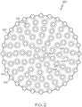
FIG. 2 is schematic illustration of an example slurry grain of an anolyte carrier slurry or a catholyte carrier slurry according to one or more embodiments shown and described herein; and -
FIG. 3 is a graphical illustration of the open-circuit voltage over the state of charge percentage of the flow redox battery system ofFig. 1 according to one or more embodiments shown and described herein. -
Fig. 1 is a schematic illustration of a flow reduction/oxidation (redox)battery system 100. The flowredox battery system 100 comprises anelectrochemical cell 110, ananolyte tank 130, acatholyte tank 140, and apower generation circuit 170. Theelectrochemical cell 110 is fluidly coupled to theanolyte tank 130 and thecatholyte tank 140 and is electrically coupled to thepower generation circuit 170. The flowredox battery system 100 comprises a firstanolyte carrier slurry 150 and a secondanolyte carrier slurry 152, which may each be housed within theanolyte tank 130 and may each flow between theanolyte tank 130 and theelectrochemical cell 110. The flowredox battery system 100 also comprises a firstcatholyte carrier slurry 154 and a secondcatholyte carrier slurry 156, which may each be housed within thecatholyte tank 140 and may each flow between thecatholyte tank 140 and theelectrochemical cell 110. Moreover, the flowredox battery system 100 includes electrolyte solutions such as an anolyte solution and a catholyte solution. - The anolyte solution may be housed within the
anolyte tank 130 and may flow between theanolyte tank 130 and theelectrochemical cell 110. The anolyte solution may comprise a plurality of charged anolyte active materials, a plurality of discharged anolyte active materials, or combinations thereof and is compositionally configured to oxidize at theelectrochemical cell 110 during a discharging operation of the flowredox battery system 100 and reduce at theelectrochemical cell 110 during a charging operation of the flowredox battery system 100. As used herein, "active material" refers to a chemical component such as an atom, ion, molecule, or the like, that is compositionally configured to change oxidation states when undergoing a redox reaction. For example, it is contemplated that the active materials of the anolyte solution may comprise vanadium, chromium, zinc, sulfur, neptunium, uranium, or a combination thereof. Moreover, each of the plurality of charged anolyte active materials comprise a lower positive charge and a lower oxidation state than each of the plurality of discharged anolyte active materials. - The catholyte solution may be housed within the
catholyte tank 140 and may flow between thecatholyte tank 140 and theelectrochemical cell 110. The catholyte solution may comprise a plurality of charged catholyte active materials, a plurality of discharged catholyte active materials, or combinations thereof and is compositionally configured to reduce at theelectrochemical cell 110 during the discharging operation and oxidize at theelectrochemical cell 100 during the charging operation. Each of the plurality of charged catholyte active materials comprise a higher positive charge and a higher oxidation state than each of the plurality of discharged catholyte active materials. For example, it is contemplated that the active materials of the catholyte solution may comprise vanadium, bromine, cerium, chlorine, ferricyanide, ferrocyanide, manganese, neptunium oxide, uranium oxide, or a combination thereof. - Further, the anolyte solution and catholyte solution may each comprise any active material having redox pairs which exhibit different standard reduction potentials. Further, the anolyte solution may comprise an active material with a lower standard reduction than the active material of the catholyte solution. The table below depicts a non-exhaustive list of active material redox pairs that may be used as the catholyte solution and the analyte solution.
Catholyte Solution Active Materials Anolyte Solution Active Materials Cr3+/Cr2+ Fe3+/F2+ V3+/N2+ V5+/V4+ V3+/V2+ Br2/Br- V3+/V2+ Fe3+/F2+ V3+/V2+ Ce4+/Ce3+ Zn2+/Zn Cl-/Cl2 Zn2+/Zn Br-/Br2 Zn2+/Zn Ce4+/Ce3+ Zn2+/Zn V5+/V4+ Zn2+/Zn [Fe(CN)6]4-/[Fe(CN)6]3- V3+/V2+ Ce4+/Ce3+ V3+/V2+ Mn3+/Mn2+ S2 2-/S4 2- Br-/Br3 - Np4+/Np3+ NpO2 +/NpO2 2+ U4+/U3+ UO2 +/UO2 2+ - As depicted in
Fig. 1 , theelectrochemical cell 110 comprises an ion-exchange membrane 120 positioned between and electrochemically engaged with ananode 112 and acathode 122. Theanode 112 includes an anodeconductive portion 116 electrically coupled to thepower generation circuit 170 such that electrons may flow between theanode 112 and thepower generation circuit 170. Theanode 112 also includes an anolyte receivingportion 114 fluidly coupled to theanolyte tank 130 such that the first and second anolyte carrier slurries 150, 152 and the anolyte solution may flow between theanolyte tank 130 and theanolyte receiving portion 114 of theanode 112. When the anolyte solution is located within theanolyte receiving portion 114, the anolyte solution may electrochemically contact the ion-exchange membrane 120 and the anodeconductive portion 116. - The
cathode 122 includes a cathodeconductive portion 126 electrically coupled to thepower generation circuit 170 such that electrons may flow between thecathode 122 and thepower generation circuit 170. Thecathode 122 also includes a catholyte receiving portion 124 fluidly coupled to thecatholyte tank 140 such that the first and secondcatholyte carrier slurries 156, 158 and the catholyte solution may flow between thecatholyte tank 140 and the catholyte receiving portion 124 of thecathode 122. When the catholyte solution is located within the catholyte receiving portion 124, the catholyte solution may electrochemically contact the ion-exchange membrane 120 and the cathodeconductive portion 126. - The ion-
exchange membrane 120 may comprise a solid state proton conducting material, for example, Nafion®, Nafion® 117, Flemion®, Fumapem®, Aciplex®, Dow® materials, Selemion®, TPS®, Gore® L01854, Gore® M04494, ABT3, ABT4, SZ, Hipore®, SPEEK, Nafion®/SPEEK, PSSS, SPTK, Radel®, PVDF-PSSA, ETFE-PDMAEMA, SPEEK/TPA, TPA/PP, SPEEK/PTFE, SPEEK/PFSA, PBI, PSf-ABIm, polybenzimidazole, polyether polymer, or the like. The ion-exchange membrane 120 is positioned within theelectrochemical cell 110 and may provide a physical barrier between theanolyte receiving portion 114 of theanode 112 and the catholyte receiving portion 124 of thecathode 122. Further, the ion-exchange membrane 120 is structurally configured to provide aproton pathway 108 between theanode 112 and thecathode 122 such that protons may flow therebetween to facilitate oxidation and reduction reactions within theanode 112 and thecathode 122 during the discharging operation and the charging operation of the flowredox battery system 100. - Further, the
proton pathway 108 of the ion-exchange membrane 120 may close a circuit between theanode 112, thepower generation circuit 170, and thecathode 122 such that oxidation and reduction reactions may generate electron flow between theanode 112 and thecathode 122 and through thepower generation circuit 170, and may generate proton flow between theanode 112 and thecathode 122 and through the ion-exchange membrane 120. For example, during the discharging operation, protons may traverse theproton pathway 108 provided by the ion-exchange membrane 120 in a proton discharging flow direction 104 from thecathode 122 to theanode 112 and during the charging operation, protons may traverse theproton pathway 108 of the ion-exchange membrane 120 in a protoncharging flow direction 105 from theanode 112 to thecathode 122. - Referring still to
Fig. 1 , thepower generation circuit 170 comprises apower generation unit 174. Thecircuit pathway 172 is electrically coupled to theanode 112, thepower generation unit 174 and thecathode 122. For example, thecircuit pathway 172 may extend between and electrically couple theanode 112 and thepower generation unit 174 and the circuit pathway may extend between and electrically coupled thecathode 122 and thepower generation unit 174. Thepower generation unit 174 may comprise a power source and an electrical load. Thepower generation unit 174 is structurally configured to receive current generated by electrons output by theanode 112 and, upon receiving current, generate power. Thepower generation unit 174 is also structurally configured to output current receivable by theanode 112 to charge the anolyte solution and the catholyte solution. - The first
anolyte carrier slurry 150 and the secondanolyte carrier slurry 152 are each compositionally configured to attract active materials of an anolyte solution and chemically engage the active materials of the anolyte solution. For example, the firstanolyte carrier slurry 150 may be compositionally configured to attract and chemically engage one of the plurality of discharged or charged anolyte active materials and the secondanolyte carrier slurry 152 may be compositionally configured to attract and chemically engage the other of the plurality of discharged or charged anolyte active materials, for example, to separate the pluralities of charged and discharged anolyte active materials within theanolyte tank 130. - Further, the first
catholyte carrier slurry 154 and the secondcatholyte carrier slurry 156 are each compositionally configured to attract active materials of the catholyte solution and chemically engage the catholyte solution. For example, the firstcatholyte carrier slurry 154 may be compositionally configured to attract and chemically engage one of the plurality of discharged or charged catholyte active materials and the secondcatholyte carrier slurry 156 may be compositionally configured to attract and chemically engage the other of the plurality of discharged or charged catholyte active materials, for example, to separate the pluralities of charged and discharged catholyte active materials. - Referring now to
Fig. 2 , the first and secondanolyte carrier slurries catholyte carrier slurries Fig. 1 may each comprise a plurality ofslurry grains 160. Eachslurry grain 160 includes aninert core 162 and one or moreactive particles 166 chemically engaged with theinert core 162. Theinert core 162 may comprise an organic particle, an inorganic particle, or a combination thereof. For example, it is contemplated that theinert core 162 may comprise alumina, silica, silicon carbide, zirconia, ceria, a polymer particle, a single metal oxide, a mixed metal oxide, or a combination thereof. Theinert core 162 of theslurry grains 160 of the firstanolyte carrier slurry 150 may have a lower density than theinert core 162 of theslurry grains 160 of the secondanolyte carrier slurry 152, such that the firstanolyte carrier slurry 150 may float above the secondanolyte carrier slurry 152. Further, theinert core 162 of theslurry grains 160 of the firstcatholyte carrier slurry 154 may have a lower density than theinert core 162 of theslurry grains 160 of the secondcatholyte carrier slurry 156, such that the firstcatholyte carrier slurry 154 may float above the secondcatholyte carrier slurry 156. - As depicted in
Fig. 2 , theslurry grains 160 further comprise one or morefunctionalized surface regions 164 positioned along the surface of theinert core 162 and one or moreactive particles 166 chemically engaged with theinert core 162 at the one or morefunctionalized surface regions 164. Thefunctionalized surface regions 164 may be chemically configured to bond with one or more functional groups of theactive particles 166, for example, using a functionalization method such as a chemo-functionalization method. It is contemplated that the one or moreactive particles 166 may comprise a metal, for example, Cu, a metal oxide, for example, ZrO2, a mixed metal, for example, Cu-Zn, a mixed metal oxide, for example, . TiO2-ZrO2, a doped metal, for example, Y2O3-ZrO2, or a combination thereof. Further, the one or moreactive particles 166 are compositionally configured to attract and chemically engage the discharged or charged catholyte active materials and the discharged or charged anolyte active materials. Moreover, the one or moreactive particles 166 of the firstanolyte carrier slurry 150 may comprise a different electronegativity the one or moreactive particles 166 of thesecond carrier slurry 152 and the one or moreactive particles 166 of the firstcatholyte carrier slurry 154 may comprise a different electronegativity than the one or moreactive particles 166 the secondcatholyte carrier slurry 156. - Referring again to
Fig. 1 , the first and secondanolyte carrier slurries anolyte carrier slurries anolyte tank 130. Further, the firstanolyte carrier slurry 150 comprises a density that is less than a density of the secondanolyte carrier slurry 152 such that the firstanolyte carrier slurry 150 floats above the secondanolyte carrier slurry 152 when the first and secondanolyte carrier slurries anolyte tank 130. Moreover, the firstanolyte carrier slurry 150 comprises an electronegativity that is different than an electronegativity of the secondanolyte carrier slurry 152 such that one of the first and secondanolyte carrier slurries anolyte carrier slurries - For example, the electronegativity of the first
anolyte carrier slurry 150 may be greater than the electronegativity of the secondanolyte carrier slurry 152 such that the firstanolyte carrier slurry 150 electrochemically attracts the plurality of discharged anolyte active materials, the secondanolyte carrier slurry 152 electrochemically attracts the plurality of charged anolyte active materials, and the plurality of discharged anolyte active materials float above the plurality of charged anolyte active materials. Moreover, the electronegativity of the firstanolyte carrier slurry 150 may be less than the electronegativity of the secondanolyte carrier slurry 152 such that the firstanolyte carrier slurry 150 electrochemically attracts the plurality of charged anolyte active materials, the secondanolyte carrier slurry 152 electrochemically attracts the plurality of discharged anolyte active materials, and the plurality of charged anolyte active materials float above the plurality of discharged anolyte active materials. - The first and second
catholyte carrier slurries catholyte carrier slurries catholyte tank 140. Further, the firstcatholyte carrier slurry 154 comprises a density that is less than a density of the secondcatholyte carrier slurry 156 such that the firstcatholyte carrier slurry 154 floats above the secondcatholyte carrier slurry 156 when the first and secondcatholyte carrier slurries catholyte tank 140. Moreover, the firstcatholyte carrier slurry 154 comprises an electronegativity that is different than an electronegativity of the secondcatholyte carrier slurry 156 such that one of the first and secondcatholyte carrier slurries catholyte carrier slurries - For example, the electronegativity of the first
catholyte carrier slurry 154 may be greater than the electronegativity of the secondcatholyte carrier slurry 156 such that the firstcatholyte carrier slurry 154 electrochemically attracts the plurality of charged catholyte active materials, the secondcatholyte carrier slurry 156 electrochemically attracts the plurality of discharged catholyte, and the plurality of charged catholyte active materials float above the plurality of discharged catholyte active materials. Moreover, the electronegativity of the firstcatholyte carrier slurry 154 may be less than the electronegativity of the secondcatholyte carrier slurry 156 such that the firstcatholyte carrier slurry 154 electrochemically attracts the plurality of discharged catholyte active materials, the secondcatholyte carrier slurry 156 electrochemically attracts the plurality of charged catholyte active materials, and the plurality of discharged catholyte active materials float above the plurality of charged catholyte active materials. - Referring again to
Fig. 1 , theanolyte tank 130 comprises an anolyteupper end 132 and an anolytelower end 134 each fluidly coupled to theanode 112. A lowdensity anolyte pathway 136 extends between and fluidly couples the anolyteupper end 132 of theanolyte tank 130 and theanode 112 and a highdensity anolyte pathway 138 extends between and fluidly couples the anolytelower end 134 of theanolyte tank 130 and theanode 112. The lowdensity anolyte pathway 136 and the highdensity anolyte pathway 138 each comprise a tube, pipe or other fluid pathway mechanism. Ananolyte pump 139 is fluidly coupled to one of the lowdensity anolyte pathway 136 or the highdensity anolyte pathway 138. Theanolyte pump 139 comprises any fluid pumping mechanism and is structurally configured to generate fluid flow between theanolyte tank 130 and theanode 112. While theanolyte pump 139 depicted inFig. 1 is fluidly coupled to the lowdensity anolyte pathway 136, theanolyte pump 139 may be fluidly coupled to the highdensity anolyte pathway 138 or multiple anolyte pumps 139 may be fluidly coupled to one or both of the lowdensity anolyte pathway 136 or the highdensity anolyte pathway 138. - The
catholyte tank 140 comprises a catholyteupper end 142 and a catholytelower end 144 each fluidly coupled to thecathode 122. A lowdensity catholyte pathway 146 extends between and fluidly couples the catholyteupper end 142 of thecatholyte tank 140 and thecathode 122 and a highdensity catholyte pathway 148 extends between and fluidly couples the catholytelower end 144 of thecatholyte tank 140 and thecathode 122. The lowdensity catholyte pathway 146 and the highdensity catholyte pathway 148 may comprise a tube, or any other fluid pathway. Acatholyte pump 149 fluidly coupled to one of the lowdensity catholyte pathway 146 or the highdensity catholyte pathway 148. Thecatholyte pump 149 comprises any fluid pumping mechanism and is structurally configured to generate fluid flow between thecatholyte tank 140 and thecathode 122. While thecatholyte pump 149 depicted inFig. 1 is fluidly coupled to the lowdensity catholyte pathway 146, thecatholyte pump 149 may be fluidly coupled to the highdensity catholyte pathway 148 or multiple catholyte pumps 149 may be coupled to one or both of the lowdensity catholyte pathway 146 or the highdensity catholyte pathway 148. - Referring again to
Fig. 1 , during the discharging operation of the flowredox battery system 100, theanode 112 may receive a charged anolyte active material chemically engaged with the first or secondanolyte carrier slurry anode 112 may also receive a proton output by thecathode 122 from theproton pathway 108 formed by the ion-exchange membrane 120 to oxidize the charged anolyte active material and chemically separate the oxidized active material from the first or secondanolyte carrier slurry anode 112. When oxidized, the charged anolyte active material outputs an electron receivable by the anodeconductive portion 116 such that the electrons flow in anelectron discharging direction 106 along thecircuit pathway 172 to thepower generation circuit 170. Moreover, after oxidation, the previously charged anolyte active material comprises a discharged anolyte active material and flows from theanode 112 back to theanolyte tank 130. - Further, during the discharging operation, when the first
anolyte carrier slurry 150 is compositionally configured to attract and chemically engage discharged anolyte active materials and the secondanolyte carrier slurry 152 is compositionally configured to attract and chemically engage charged anolyte active materials such that the discharged anolyte active materials float above the charged anolyte active materials, theanolyte pump 139 may generate fluid flow in afirst flow direction 102 from the anolytelower end 134 to theanode 112 and from theanode 112 to the anolyteupper end 132. Thus, the charged anolyte active materials chemically engaged with the higher density secondanolyte carrier slurry 152 may flow along the highdensity anolyte pathway 138 in thefirst flow direction 102 from the anolytelower end 134 to theanode 112 such thatanode 112 fills with charged anolyte active materials compositionally configured to undergo oxidation and discharge. - After oxidation, the now discharged anolyte active materials may flow along the low
density anolyte pathway 136 in thefirst flow direction 102 from theanode 112 to the anolyteupper end 132 such that the firstanolyte carrier slurry 150 floating above the secondanolyte carrier slurry 152 may attract and chemically engage the discharged anolyte active materials. Moreover, when the firstanolyte carrier slurry 150 is compositionally configured to chemically attract and engage the charged anolyte active materials and the secondanolyte carrier slurry 152 is compositionally configured to chemically attract and engage the discharged anolyte active materials such that the charged anolyte active materials float above the discharged anolyte active materials, theanolyte pump 139 may generate fluid flow in asecond flow direction 103 from the anolyteupper end 132 to theanode 112 and from theanode 112 to the anolytelower end 134. - During the discharging operation, the
cathode 122 may receive a charged catholyte active material chemically engaged with the first or secondcatholyte carrier slurry cathode 122 may also receive an electron from thepower generation circuit 170 to reduce the charged catholyte active material and chemically separate the charged catholyte active material from the first or secondcatholyte carrier slurry proton pathway 108 of the ion-exchange membrane 120 (for example, the proton received by the anode 112). Moreover, after reduction, the previously charged catholyte active material comprises a discharged catholyte active material and flows from thecathode 122 back to thecatholyte tank 140. - Further, during the discharging operation, when the first
catholyte carrier slurry 154 is compositionally configured to attract and chemically engage discharged catholyte active materials and the secondcatholyte carrier slurry 156 is compositionally configured to attract and chemically engage charged catholyte active materials such that the discharged anolyte active materials float above the charged catholyte active materials, thecatholyte pump 149 may generate fluid flow in thefirst flow direction 102 from the catholytelower end 144 to thecathode 122 and from thecathode 122 to the catholyteupper end 142. Thus, the charged catholyte active materials chemically engaged with the higher density secondcatholyte carrier slurry 156 may flow along the highdensity catholyte pathway 148 in thefirst flow direction 102 from the catholytelower end 144 to thecathode 122, such thatcathode 122 fills with charged catholyte active materials compositionally configured to undergo reduction and discharge. - After reduction, the now discharged catholyte active material may flow along the low
density catholyte pathway 146 in thefirst flow direction 102 from thecathode 122 to the catholyteupper end 142 such that the firstcatholyte carrier slurry 154 floating above the secondcatholyte carrier slurry 156 may attract and chemically engage the discharged catholyte active material. Moreover, when the firstcatholyte carrier slurry 154 is compositionally configured to attract and chemically engage the charged catholyte active materials and the secondcatholyte carrier slurry 156 is compositionally configured to attract and chemically engage the discharged catholyte active materials such that the charged catholyte active materials float above the charged catholyte active materials, thecatholyte pump 149 may generate fluid flow in thesecond flow direction 103 from the catholyteupper end 142 to thecathode 122 and from thecathode 122 to the catholytelower end 144. - Referring still to
Fig. 1 , during the charging operation of the flowredox battery system 100, theanode 112 may receive the discharged anolyte active material chemically engaged with the first or secondanolyte carrier slurry anode 112 may also receive an electron from thepower generation circuit 170 to reduce the discharged anolyte active material and chemically separate the discharged anolyte active material from the first or secondanolyte carrier slurry proton pathway 108 of the ion-exchange membrane 120. Moreover, after reduction, the previously discharged anolyte active material comprises a charged anolyte active material and flows from theanode 112 back to theanolyte tank 130. - Further, during the charging operation, when the first
anolyte carrier slurry 150 is compositionally configured to attract and chemically engage discharged anolyte active materials and the secondanolyte carrier slurry 152 is compositionally configured to attract and chemically engage charged anolyte active materials such that the discharged anolyte active materials float above the charged anolyte active materials, theanolyte pump 139 may generate fluid flow in thesecond flow direction 103 from the anolyteupper end 132 to theanode 112 and from theanode 112 to the anolytelower end 134. Thus, the discharged anolyte active materials chemically engaged with the lower density firstanolyte carrier slurry 150 may flow along the lowdensity anolyte pathway 136 in thesecond flow direction 103 from the anolyteupper end 132 to theanode 112, such thatanode 112 fills with discharged anolyte active materials compositionally configured to undergo reduction and charge. - After reduction, the now charged anolyte active material may flow along the high
density anolyte pathway 138 in thesecond flow direction 103 from theanode 112 to the anolytelower end 134 such that the secondanolyte carrier slurry 152 positioned below the firstanolyte carrier slurry 150 may attract and chemically engage the charged anolyte active material. Moreover, when the firstanolyte carrier slurry 150 is compositionally configured to attract and chemically engage the charged anolyte active material and the secondanolyte carrier slurry 152 is compositionally configured to attract and chemically engage the discharged anolyte active materials such that the charged anolyte active materials float above the discharged anolyte active materials, theanolyte pump 139 may generate fluid flow in thefirst flow direction 102 from the anolyteupper end 132 to theanode 112 and from theanode 112 to the anolytelower end 134. - During the charging operation, the
cathode 122 may receive the discharged catholyte active material chemically engaged with the first or secondcatholyte carrier slurry cathode 122 may also receive the proton output by theanode 112 from theproton pathway 108 formed by the ion-exchange membrane 120 to oxidize the discharged catholyte active material and chemically separate the oxidized active material from the first or secondcatholyte carrier slurry cathode 122. When oxidized, the discharged catholyte active material outputs an electron receivable by thecathode conductive port 126 such that the electrons flow in anelectron charging direction 107 along thecircuit pathway 172 to thepower generation circuit 170. Moreover, after oxidation, the previously discharged catholyte active material comprises a charged catholyte active material and flows from thecathode 122 back to thecatholyte tank 140. - Further, during the charging operation, when the first
catholyte carrier slurry 154 is compositionally configured to attract and chemically engage discharged catholyte active materials and the secondcatholyte carrier slurry 156 is compositionally configured to attract and chemically engage charged catholyte active materials such that the discharged catholyte active materials float above the charged catholyte active materials, thecatholyte pump 149 may generate fluid flow in thesecond flow direction 103 from the catholyteupper end 142 to thecathode 122 and from thecathode 122 to the catholytelower end 144. Thus, the discharged catholyte active materials chemically engaged with the lower density firstcatholyte carrier slurry 154 may flow along the lowdensity catholyte pathway 146 in thesecond flow direction 103 from the catholyteupper end 142 to thecathode 122, such thatcathode 122 fills with discharged catholyte active materials compositionally configured to undergo oxidation and charge. - After oxidation, the now charged catholyte active material may flow along the high
density catholyte pathway 148 in thesecond flow direction 103 from thecathode 122 to the catholytelower end 144 such that the secondcatholyte carrier slurry 156 positioned below the firstcatholyte carrier slurry 154 may attract and chemically engage the charged catholyte active material. Moreover, when the firstcatholyte carrier slurry 154 is compositionally configured to attract and chemically engage the charged catholyte active materials and the secondcatholyte carrier slurry 156 is compositionally configured to attract and chemically engage the discharged catholyte active materials such that the charged catholyte active materials float above the charged catholyte active materials, thecatholyte pump 149 may generate fluid flow in thefirst flow direction 102 from the catholyteupper end 142 to thecathode 122 and from thecathode 122 to the catholytelower end 144. - In operation, an increased concentration of reactant anolyte active materials within the
anode 112 and reactant catholyte active materials within thecathode 122 during operation of theelectrochemical cell 110 decreases the electrochemical loss of the flowredox battery system 100. For example, when discharging the flowredox battery system 100, charged anolyte active materials are reactant anolyte active materials and charged catholyte active materials are reactant catholyte active materials and when charging the flowredox battery system 100, discharged anolyte active materials are the reactant anolyte active materials and discharged catholyte active materials are the reactant catholyte active materials. Accordingly, separating the charged and discharged anolyte active materials within theanolyte tank 130 and separating the charged and discharged catholyte active materials withincatholyte tank 140 and selectively pumping reactant anolyte active materials into theanode 112 and reactant catholyte active materials into thecathode 122 may increase the efficiency of the flowredox battery system 100 by reducing electrochemical losses of the flowredox battery system 100. - For example, the flow
redox battery system 100 comprises an open-circuit voltage VOC or electromotive force (EMF), which is the maximum voltage that may be generated by the flowredox battery system 100 under open-circuit conditions, for example, when there is zero current in thepower generation circuit 170. The open-circuit voltage VOC is affected by the reduction and oxidation reactions at theelectrochemical cell 110, the concentration of the reactant anolyte active materials in theanode 112 and reactant catholyte active materials in the cathode 122 (the Nernst voltage) and the operation temperature. - The open-circuit voltage VOC of the flow
redox battery system 100 may be mathematically described as

anode 112 and thecathode 122, R is the universal gas constant, T is the operation temperature of theelectrochemical cell 110, n is the number of moles of electrons transferred in theelectrochemical cell 110 redox half-reactions, for example, the number of moles of electrons transferred between the anolyte solution and the catholyte solution along thecircuit pathway 172, F is the Faraday constant, which is 96485 coulomb/mol, aox is the activity of the oxidant species (for example, the anolyte solution during a discharging operation or the catholyte solution during the charging operation) and ared is the activity of the reductant species (for example, the anolyte solution during the charging operation or the catholyte solution during the discharging operation). - The activity ratio

redox battery system 100. For example, the activity ratio is maximized at full charge. Further, the activity ratio decreases at a lower charge, because the concentration of the reactant active materials decreases and the concentration of the non-reactant active materials increases, which may decrease the open-circuit voltage VOC. Accordingly, separating the charged and discharged anolyte and catholyte active materials in each of the anolyte and catholyte solutions may maximize the concentration of reactant active materials within theelectrochemical cell 110 and increase the open-circuit voltage VOC of the flowredox battery system 100. - As an illustrative example, when the anolyte solution comprises vanadium, the plurality of charged anolyte active materials may each comprise V 2+ and the plurality of discharged anolyte active materials may each comprise V 3+. During the discharging operation, the oxidation reaction at the
anode 112 may be chemically described as V 2+ → V 3+ + e-. At theanode 112, the charged anolyte active material V 2+ is oxidized into the discharged anolyte active material V 3+ and an electron e - is output into thecircuit pathway 172 of thepower generation circuit 170. The voltage generated theanode 112 at about 25 °C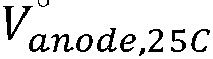
anode 112 may be chemically described as V 3+ + e- →V2+. - When the catholyte solution comprises vanadium, the plurality of charged catholyte active materials may each comprise V 5+ (for example,

cathode 122 may be chemically described as
cathode 122, the charged catholyte active material
circuit pathway 172 of thepower generation circuit 170, for example, electron e - output by theanode 112 during the oxidation reaction. The voltage generated thecathode 122 at about 25 °C
cathode 122 may be chemically described as
- Moreover, an electrode potential of the anode 112
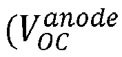


electrochemical cell 110, [VO 2+] is the concentration of discharged catholyte active materials in theelectrochemical cell 110, [V 2+] is the concentration of charged anolyte active materials in theelectrochemical cell 110, [V 3+] is the concentration of discharged anolyte active materials in theelectrochemical cell 110, and [H +] is the concentration of H + protons in theelectrochemical cell 110. - The
electrochemical cell 110 also comprises a Donnan overpotential VDon, which is generated along theproton pathway 108 of the ion-exchange membrane 120 by the H + proton concentration difference between theanode 112 and thecathode 122. The Donnan overpotential may be mathematically described as
cathode 122 and [H +] anode is the concentration of H + protons in theanode 112. Accordingly, the overall open-circuit voltage of the flow redox battery system 100


- Further, the amount of charge remaining within the flow
redox battery system 100 is a state of charge (SOC) and may be mathematically represented by

anode 112 or thecathode 122, for example, the difference between the original H + proton concentration and the current H + proton. Thus, the overall open-circuit voltage of the flow redox battery system 100

- Separating the charged and discharged anolyte active materials and charged and discharged catholyte active materials within the
anolyte tank 130 and thecatholyte tank 140, respectively, may minimize the recirculation of the reactant active materials back to theanolyte tank 130 and thecatholyte tank 140, respectively and minimize the amount of non-reactant active materials introduced into theelectrochemical cell 110. This increases the open circuit voltage of the flowredox battery system 100 because the concentrations of the products reactant active materials may be constant during operation, as mathematically described by [A β+] = a[A α+]° and [B γ+] = a[B δ+]°, where α is the percentage of the reactant active materials re-circulated back to theanolyte tank 130 andcatholyte tank 140, respectively, and [Aα+]° and [Bδ+]° are the initial (full charge) concentration of the reactant active materials, respectively. Thus, the state of charge SOC may be mathematically described as

- Referring now to
Fig. 3 , agraph 190 is depicted showing the open-circuit voltage
redox battery system 100.Curve 194, labeled "mixed active materials" depicts the open-circuit voltage
redox battery system 100 without the anolyte orcatholyte carrier slurries anolyte tank 130 and theanode 112 and the charged and discharged catholyte active materials are mixed within both thecatholyte tank 140 and thecathode 122.Curve 192, labeled "carrier slurry separated active materials" depicts the open-circuit voltage
redox battery system 100 using anolyte andcatholyte carrier slurries anolyte tank 130 separate the charged and discharged catholyte active materials within thecatholyte tank 140, as described supra. As depicted inFig. 3 ,curve 192 shows a higher open circuit voltage
redox battery system 100 when compared tocurve 194. Further, as the SOC percentage decreases, the gap between the open circuit voltage ofcurve 192 andcurve 194 increases. - It is noted that recitations herein of a component of the present disclosure being "configured" in a particular way, to embody a particular property, or to function in a particular manner, are structural recitations, as opposed to recitations of intended use. More specifically, the references herein to the manner in which a component is "configured" denotes an existing physical condition of the component and, as such, is to be taken as a definite recitation of the structural characteristics of the component.
- For the purposes of describing and defining the present invention it is noted that the term "about" is utilized herein to represent the inherent degree of uncertainty that may be attributed to any quantitative comparison, value, measurement, or other representation. The term "about" is also utilized herein to represent the degree by which a quantitative representation may vary from a stated reference without resulting in a change in the basic function of the subject matter at issue.
- Having described the subject matter of the present disclosure in detail and by reference to specific embodiments thereof, it is noted that the various details disclosed herein should not be taken to imply that these details relate to elements that are essential components of the various embodiments described herein, even in cases where a particular element is illustrated in each of the drawings that accompany the present description. More specifically, although some aspects of the present disclosure are identified herein as preferred or particularly advantageous, it is contemplated that the present disclosure is not necessarily limited to these aspects.
- It is noted that one or more of the following claims utilize the term "wherein" as a transitional phrase. For the purposes of defining the present invention, it is noted that this term is introduced in the claims as an open-ended transitional phrase that is used to introduce a recitation of a series of characteristics of the structure and should be interpreted in like manner as the more commonly used open-ended preamble term "comprising."
Claims (12)
- A flow redox battery system (100) comprising an electrochemical cell (110), an anolyte tank (130), a catholyte tank (140), a first anolyte carrier slurry (150), a second anolyte carrier slurry (152), a first catholyte carrier slurry (154), a second catholyte carrier slurry (156), and a power generation circuit (170), wherein:the electrochemical cell (110) comprises an ion-exchange membrane (120) positioned between and electrochemically engaged with an anode (112) and a cathode (122);the power generation circuit (170) is electrically coupled to the anode (112) and the cathode (122);the anolyte tank (130) comprises an anolyte upper end (132) fluidly coupled to the anode (112) and an anolyte lower end (134) fluidly coupled to the anode (112);the catholyte tank (140) comprises a catholyte upper end (142) fluidly coupled to the cathode (122) and a catholyte lower end (144) fluidly coupled to the cathode (122);the first anolyte carrier slurry (150) comprises a density that is less than a density of the second anolyte carrier slurry and an electronegativity that is different than an electronegativity of the second anolyte carrier slurry (152), wherein the first and second anolyte carrier slurries each comprise a plurality of slurry grains, each slurry grain comprising an inert core and one or more active particles chemically engaged with the inert core;the first catholyte carrier slurry (154) comprises a density that is less than a density of the second catholyte carrier slurry and an electronegativity that is different than an electronegativity of the second catholyte carrier slurry (156), wherein the first and second catholyte carrier slurries each comprise a plurality of slurry grains, each slurry grain comprising an inert core and one or more active particles chemically engaged with the inert core;the first anolyte carrier slurry floats above the second anolyte carrier slurry when the first and second anolyte carrier slurries are housed within the anolyte tank; andthe first catholyte carrier slurry floats above the second catholyte carrier slurry when the first and second catholyte carrier slurries are housed within the catholyte tank.
- The flow redox battery system (100) of claim 1, wherein when the electronegativity of the first anolyte carrier slurry (150) is greater than the electronegativity of the second anolyte carrier slurry (152), the first anolyte carrier slurry (150) electrochemically attracts a discharged anolyte active material and the second anolyte carrier slurry (152) electrochemically attracts a charged anolyte active material, or wherein the electronegativity of the first anolyte carrier slurry (150) is less than the electronegativity of the second anolyte carrier slurry (152), the first anolyte carrier slurry (150) electrochemically attracts a charged anolyte active material and the second anolyte carrier slurry (152) electrochemically attracts a discharged anolyte active material.
- The flow redox battery system (100) of claim 1, wherein the electronegativity of the first catholyte carrier slurry (154) is greater than the electronegativity of the second catholyte carrier slurry (156), the first catholyte carrier slurry (154) electrochemically attracts a charged catholyte active material and the second catholyte carrier slurry (156) electrochemically attracts a discharged catholyte, or wherein when the electronegativity of the first catholyte carrier slurry (154) is less than the electronegativity of the second catholyte carrier slurry (156), the first catholyte carrier slurry (154) electrochemically attracts a discharged catholyte and the second catholyte carrier slurry (156) electrochemically attracts a charged catholyte active material.
- The flow redox battery system (100) of claim 1, further comprising a low density anolyte pathway (136) that extends between and fluidly couples the anolyte upper end (132) of the anolyte tank (130) and the anode (112) and a high density anolyte pathway (138) that extends between and fluidly couples the anolyte lower end (134) of the anolyte tank (130) and the anode (112); and further comprising a low density catholyte pathway (146) that extends between and fluidly couples the catholyte upper end (142) of the catholyte tank (140) and the cathode (122) and a high density catholyte pathway (148) that extends between and fluidly couples the catholyte lower end (144) of the catholyte tank (140) and the cathode (122).
- The flow redox battery system (100) of claim 1, further comprising an anolyte solution disposed within the anolyte tank (130) to be chemically engageable with the first anolyte carrier slurry (150) and the second anolyte carrier slurry (152); and further comprising a catholyte solution chemically engageable with the first catholyte carrier slurry (154) and the second catholyte carrier slurry (156).
- The flow redox battery system (100) of claim 5, wherein one or more active materials of the anolyte solution comprises vanadium, chromium, zinc, sulfur, or a combination thereof.
- The flow redox battery system (100) of claim 5, wherein the anode (122) is electrochemically configured to:chemically separate a charged anolyte active material from the first or second anolyte carrier slurry (150, 152) and oxidize the charged anolyte active material such that the charged anolyte active material outputs an electron receivable by the power generation circuit (170) upon receiving both the charged anolyte active material chemically engaged with the first or second anolyte carrier slurry (150, 152) and a proton from the ion-exchange membrane (120); andchemically separate a discharged anolyte active material from the first or second anolyte carrier slurry (150, 152) and reduce the discharged anolyte active material such that the discharged anolyte active material outputs a proton receivable by the ion-exchange membrane (120) upon receiving both the discharged anolyte active material chemically engaged with the first or second anolyte carrier slurry (150, 152) and an electron from the power generation circuit (170).
- The flow redox battery system (100) of claim 5, wherein one or more active materials of the catholyte solution comprises vanadium, bromine, cerium, chlorine, ferricyanide, ferrocyanide, manganese, or a combination thereof.
- The flow redox battery system (100) of claim 5, wherein the cathode (122) is electrochemically configured to:chemically separate a charged catholyte active material from the first or second catholyte carrier slurry (154, 156) and reduce the charged catholyte active material such that the charged catholyte active material outputs a proton receivable by the ion-exchange membrane (120) upon receiving both the charged catholyte active material chemically engaged with the first or second catholyte carrier slurry (154, 156) and an electron from the power generation circuit (170); andchemically separate a discharged catholyte active material from the first or second catholyte carrier slurry (154, 156) and oxidize the discharged catholyte active material such that the discharged catholyte active material outputs an electron receivable by the power generation circuit (170) upon receiving both the discharged catholyte active material chemically engaged with the first or second catholyte carrier slurry (154, 156) and a proton from the ion-exchange membrane (120).
- The flow redox battery system (100) of claim 1, wherein the ion-exchange membrane (120) comprises a solid state proton conducting material structurally configured to provide a proton pathway between the anode (112) and the cathode (112).
- A flow redox battery system (100) according to claim 1, wherein:the anolyte solution is chemically engageable with the first anolyte carrier slurry (150) and the second anolyte carrier slurry (152);the catholyte solution is chemically engageable with the first catholyte carrier slurry (154) and the second catholyte carrier slurry (156).
- The flow redox battery system (100) of claim 1, wherein the inert core (162) comprises one or more functionalized surface regions (164) and the one or more active particles (166) are chemically engaged with the inert core (162) at the one or more functionalized surface regions (164).
Applications Claiming Priority (2)
| Application Number | Priority Date | Filing Date | Title |
|---|---|---|---|
| US15/072,912 US10069161B2 (en) | 2016-03-17 | 2016-03-17 | In-situ gravitational separation of electrolyte solutions in flow redox battery systems |
| PCT/US2017/022092 WO2017160712A1 (en) | 2016-03-17 | 2017-03-13 | In-situ gravitational separation of electrolyte solutions in flow redox battery systems |
Publications (2)
| Publication Number | Publication Date |
|---|---|
| EP3430668A1 EP3430668A1 (en) | 2019-01-23 |
| EP3430668B1 true EP3430668B1 (en) | 2021-05-26 |
Family
ID=58387982
Family Applications (1)
| Application Number | Title | Priority Date | Filing Date |
|---|---|---|---|
| EP17712677.8A Active EP3430668B1 (en) | 2016-03-17 | 2017-03-13 | In-situ gravitational separation of electrolyte solutions in flow redox battery systems |
Country Status (8)
| Country | Link |
|---|---|
| US (1) | US10069161B2 (en) |
| EP (1) | EP3430668B1 (en) |
| JP (1) | JP2019508866A (en) |
| KR (1) | KR102217398B1 (en) |
| CN (1) | CN108780912B (en) |
| SA (1) | SA518400041B1 (en) |
| SG (1) | SG11201807925RA (en) |
| WO (1) | WO2017160712A1 (en) |
Families Citing this family (2)
| Publication number | Priority date | Publication date | Assignee | Title |
|---|---|---|---|---|
| EP3671928A1 (en) * | 2018-12-21 | 2020-06-24 | Fundación Imdea Energía | Redox-flow battery for energy storage |
| WO2024175589A1 (en) * | 2023-02-24 | 2024-08-29 | Litricity Gmbh | Redox battery system |
Family Cites Families (12)
| Publication number | Priority date | Publication date | Assignee | Title |
|---|---|---|---|---|
| JPS58176880A (en) * | 1982-04-12 | 1983-10-17 | Agency Of Ind Science & Technol | Operation control method of redox-flow type battery |
| WO2002095855A1 (en) * | 2001-05-18 | 2002-11-28 | Unisearch Limited | Vanadium redox battery electrolyte |
| US9786944B2 (en) | 2008-06-12 | 2017-10-10 | Massachusetts Institute Of Technology | High energy density redox flow device |
| US20130011702A1 (en) | 2008-07-07 | 2013-01-10 | Enervault Corporation | Redox Flow Battery System with Divided Tank System |
| US7820321B2 (en) | 2008-07-07 | 2010-10-26 | Enervault Corporation | Redox flow battery system for distributed energy storage |
| CA2757969C (en) | 2009-04-06 | 2018-01-09 | 24M Technologies, Inc. | Fuel system using redox flow battery |
| WO2010143634A1 (en) * | 2009-06-09 | 2010-12-16 | シャープ株式会社 | Redox flow battery |
| WO2011137239A1 (en) * | 2010-04-28 | 2011-11-03 | Flexel, Llc | A thin flexible electrochemical energy cell |
| CN103155257B (en) * | 2010-08-18 | 2016-08-17 | 麻省理工学院 | Fixing liquid redox electrode |
| CN103620845B (en) | 2011-06-27 | 2016-10-05 | 住友电气工业株式会社 | Redox flow batteries |
| KR101327741B1 (en) * | 2011-10-19 | 2013-11-11 | 한국에너지기술연구원 | Nanoparticles as a support for redox couple and redox flow battery including the same |
| CN103618094B (en) | 2013-12-02 | 2016-03-16 | 浙江大学 | The preparation method of a kind of high-capacity lithium sulfur flow battery and electrode thereof |
-
2016
- 2016-03-17 US US15/072,912 patent/US10069161B2/en active Active
-
2017
- 2017-03-13 CN CN201780018078.8A patent/CN108780912B/en active Active
- 2017-03-13 SG SG11201807925RA patent/SG11201807925RA/en unknown
- 2017-03-13 WO PCT/US2017/022092 patent/WO2017160712A1/en not_active Ceased
- 2017-03-13 EP EP17712677.8A patent/EP3430668B1/en active Active
- 2017-03-13 JP JP2018548914A patent/JP2019508866A/en active Pending
- 2017-03-13 KR KR1020187028409A patent/KR102217398B1/en active Active
-
2018
- 2018-09-17 SA SA518400041A patent/SA518400041B1/en unknown
Non-Patent Citations (1)
| Title |
|---|
| None * |
Also Published As
| Publication number | Publication date |
|---|---|
| JP2019508866A (en) | 2019-03-28 |
| KR20180124057A (en) | 2018-11-20 |
| SG11201807925RA (en) | 2018-10-30 |
| CN108780912A (en) | 2018-11-09 |
| US10069161B2 (en) | 2018-09-04 |
| KR102217398B1 (en) | 2021-02-22 |
| US20170271703A1 (en) | 2017-09-21 |
| SA518400041B1 (en) | 2022-05-08 |
| EP3430668A1 (en) | 2019-01-23 |
| CN108780912B (en) | 2021-10-08 |
| WO2017160712A1 (en) | 2017-09-21 |
Similar Documents
| Publication | Publication Date | Title |
|---|---|---|
| US12512499B2 (en) | Methods and systems for determining average oxidation state of redox flow battery systems | |
| US12451528B2 (en) | In-situ electrolyte preparation in flow battery | |
| US7927731B2 (en) | Redox flow cell | |
| JP6549572B2 (en) | Redox flow battery and method for balancing the charge state of the flow battery | |
| KR102380325B1 (en) | Electrochemical-based purification of electrolyte solutions, and related systems and methods | |
| EP3240083A1 (en) | Method of operating redox flow battery, and redox flow battery system | |
| US10014547B2 (en) | Flow battery | |
| US20150380760A1 (en) | ALL-VANADIUM REDOX FLOW BATTERY SYSTEM EMPLOYING A V+4/V+5 REDOX COUPLE AND AN ANCILLARY Ce+3/Ce+4 REDOX COUPLE IN THE POSITIVE ELECTROLYTE SOLUTION | |
| EP3277861B1 (en) | Method of treating liquid electrolyte solution | |
| EP3087628B1 (en) | Distribution of electrolytes in a flow battery | |
| Lee et al. | Analysis of the effect of MnO2 precipitation on the performance of a vanadium/manganese redox flow battery | |
| EP3566257B1 (en) | Mechanical energy storage in flow batteries to enhance energy storage | |
| US11831054B2 (en) | Method of maintaining health of a flow battery | |
| Loktionov et al. | Reduction of VO2+ in electrolysis cell combined with chemical regeneration of oxidized VO2+ electrolyte for operando capacity recovery of vanadium redox flow battery | |
| US20150349369A1 (en) | High-Energy-Density, Nonaqueous, Redox Flow Batteries Having Iodine-based Species | |
| EP3742534B1 (en) | Redox flow battery system with electrochemical recovery cell | |
| US10069161B2 (en) | In-situ gravitational separation of electrolyte solutions in flow redox battery systems | |
| US20140377681A1 (en) | Air-breathing fuel cell and cell stack for the oxidation of ions using oxygen | |
| KR102144745B1 (en) | Redox Flow Battery with Porous Electrode in Which Mixing Plate Is Inserted | |
| EP3067977A1 (en) | Method for operating redox flow battery | |
| JP2018503222A (en) | Method for regenerating electrolyte solution of redox flow battery |
Legal Events
| Date | Code | Title | Description |
|---|---|---|---|
| STAA | Information on the status of an ep patent application or granted ep patent |
Free format text: STATUS: UNKNOWN |
|
| STAA | Information on the status of an ep patent application or granted ep patent |
Free format text: STATUS: THE INTERNATIONAL PUBLICATION HAS BEEN MADE |
|
| PUAI | Public reference made under article 153(3) epc to a published international application that has entered the european phase |
Free format text: ORIGINAL CODE: 0009012 |
|
| STAA | Information on the status of an ep patent application or granted ep patent |
Free format text: STATUS: REQUEST FOR EXAMINATION WAS MADE |
|
| 17P | Request for examination filed |
Effective date: 20181017 |
|
| AK | Designated contracting states |
Kind code of ref document: A1 Designated state(s): AL AT BE BG CH CY CZ DE DK EE ES FI FR GB GR HR HU IE IS IT LI LT LU LV MC MK MT NL NO PL PT RO RS SE SI SK SM TR |
|
| AX | Request for extension of the european patent |
Extension state: BA ME |
|
| DAV | Request for validation of the european patent (deleted) | ||
| DAX | Request for extension of the european patent (deleted) | ||
| STAA | Information on the status of an ep patent application or granted ep patent |
Free format text: STATUS: EXAMINATION IS IN PROGRESS |
|
| 17Q | First examination report despatched |
Effective date: 20200514 |
|
| GRAP | Despatch of communication of intention to grant a patent |
Free format text: ORIGINAL CODE: EPIDOSNIGR1 |
|
| STAA | Information on the status of an ep patent application or granted ep patent |
Free format text: STATUS: GRANT OF PATENT IS INTENDED |
|
| INTG | Intention to grant announced |
Effective date: 20201221 |
|
| GRAS | Grant fee paid |
Free format text: ORIGINAL CODE: EPIDOSNIGR3 |
|
| GRAA | (expected) grant |
Free format text: ORIGINAL CODE: 0009210 |
|
| STAA | Information on the status of an ep patent application or granted ep patent |
Free format text: STATUS: THE PATENT HAS BEEN GRANTED |
|
| AK | Designated contracting states |
Kind code of ref document: B1 Designated state(s): AL AT BE BG CH CY CZ DE DK EE ES FI FR GB GR HR HU IE IS IT LI LT LU LV MC MK MT NL NO PL PT RO RS SE SI SK SM TR |
|
| REG | Reference to a national code |
Ref country code: GB Ref legal event code: FG4D |
|
| REG | Reference to a national code |
Ref country code: CH Ref legal event code: EP |
|
| REG | Reference to a national code |
Ref country code: AT Ref legal event code: REF Ref document number: 1397139 Country of ref document: AT Kind code of ref document: T Effective date: 20210615 |
|
| REG | Reference to a national code |
Ref country code: DE Ref legal event code: R096 Ref document number: 602017039216 Country of ref document: DE |
|
| REG | Reference to a national code |
Ref country code: IE Ref legal event code: FG4D |
|
| REG | Reference to a national code |
Ref country code: NL Ref legal event code: FP |
|
| REG | Reference to a national code |
Ref country code: LT Ref legal event code: MG9D |
|
| REG | Reference to a national code |
Ref country code: NO Ref legal event code: T2 Effective date: 20210526 |
|
| REG | Reference to a national code |
Ref country code: AT Ref legal event code: MK05 Ref document number: 1397139 Country of ref document: AT Kind code of ref document: T Effective date: 20210526 |
|
| PG25 | Lapsed in a contracting state [announced via postgrant information from national office to epo] |
Ref country code: LT Free format text: LAPSE BECAUSE OF FAILURE TO SUBMIT A TRANSLATION OF THE DESCRIPTION OR TO PAY THE FEE WITHIN THE PRESCRIBED TIME-LIMIT Effective date: 20210526 Ref country code: FI Free format text: LAPSE BECAUSE OF FAILURE TO SUBMIT A TRANSLATION OF THE DESCRIPTION OR TO PAY THE FEE WITHIN THE PRESCRIBED TIME-LIMIT Effective date: 20210526 Ref country code: HR Free format text: LAPSE BECAUSE OF FAILURE TO SUBMIT A TRANSLATION OF THE DESCRIPTION OR TO PAY THE FEE WITHIN THE PRESCRIBED TIME-LIMIT Effective date: 20210526 Ref country code: BG Free format text: LAPSE BECAUSE OF FAILURE TO SUBMIT A TRANSLATION OF THE DESCRIPTION OR TO PAY THE FEE WITHIN THE PRESCRIBED TIME-LIMIT Effective date: 20210826 Ref country code: AT Free format text: LAPSE BECAUSE OF FAILURE TO SUBMIT A TRANSLATION OF THE DESCRIPTION OR TO PAY THE FEE WITHIN THE PRESCRIBED TIME-LIMIT Effective date: 20210526 |
|
| PG25 | Lapsed in a contracting state [announced via postgrant information from national office to epo] |
Ref country code: GR Free format text: LAPSE BECAUSE OF FAILURE TO SUBMIT A TRANSLATION OF THE DESCRIPTION OR TO PAY THE FEE WITHIN THE PRESCRIBED TIME-LIMIT Effective date: 20210827 Ref country code: LV Free format text: LAPSE BECAUSE OF FAILURE TO SUBMIT A TRANSLATION OF THE DESCRIPTION OR TO PAY THE FEE WITHIN THE PRESCRIBED TIME-LIMIT Effective date: 20210526 Ref country code: IS Free format text: LAPSE BECAUSE OF FAILURE TO SUBMIT A TRANSLATION OF THE DESCRIPTION OR TO PAY THE FEE WITHIN THE PRESCRIBED TIME-LIMIT Effective date: 20210926 Ref country code: SE Free format text: LAPSE BECAUSE OF FAILURE TO SUBMIT A TRANSLATION OF THE DESCRIPTION OR TO PAY THE FEE WITHIN THE PRESCRIBED TIME-LIMIT Effective date: 20210526 Ref country code: RS Free format text: LAPSE BECAUSE OF FAILURE TO SUBMIT A TRANSLATION OF THE DESCRIPTION OR TO PAY THE FEE WITHIN THE PRESCRIBED TIME-LIMIT Effective date: 20210526 Ref country code: PT Free format text: LAPSE BECAUSE OF FAILURE TO SUBMIT A TRANSLATION OF THE DESCRIPTION OR TO PAY THE FEE WITHIN THE PRESCRIBED TIME-LIMIT Effective date: 20210927 Ref country code: PL Free format text: LAPSE BECAUSE OF FAILURE TO SUBMIT A TRANSLATION OF THE DESCRIPTION OR TO PAY THE FEE WITHIN THE PRESCRIBED TIME-LIMIT Effective date: 20210526 |
|
| PG25 | Lapsed in a contracting state [announced via postgrant information from national office to epo] |
Ref country code: SM Free format text: LAPSE BECAUSE OF FAILURE TO SUBMIT A TRANSLATION OF THE DESCRIPTION OR TO PAY THE FEE WITHIN THE PRESCRIBED TIME-LIMIT Effective date: 20210526 Ref country code: SK Free format text: LAPSE BECAUSE OF FAILURE TO SUBMIT A TRANSLATION OF THE DESCRIPTION OR TO PAY THE FEE WITHIN THE PRESCRIBED TIME-LIMIT Effective date: 20210526 Ref country code: RO Free format text: LAPSE BECAUSE OF FAILURE TO SUBMIT A TRANSLATION OF THE DESCRIPTION OR TO PAY THE FEE WITHIN THE PRESCRIBED TIME-LIMIT Effective date: 20210526 Ref country code: ES Free format text: LAPSE BECAUSE OF FAILURE TO SUBMIT A TRANSLATION OF THE DESCRIPTION OR TO PAY THE FEE WITHIN THE PRESCRIBED TIME-LIMIT Effective date: 20210526 Ref country code: EE Free format text: LAPSE BECAUSE OF FAILURE TO SUBMIT A TRANSLATION OF THE DESCRIPTION OR TO PAY THE FEE WITHIN THE PRESCRIBED TIME-LIMIT Effective date: 20210526 Ref country code: CZ Free format text: LAPSE BECAUSE OF FAILURE TO SUBMIT A TRANSLATION OF THE DESCRIPTION OR TO PAY THE FEE WITHIN THE PRESCRIBED TIME-LIMIT Effective date: 20210526 Ref country code: DK Free format text: LAPSE BECAUSE OF FAILURE TO SUBMIT A TRANSLATION OF THE DESCRIPTION OR TO PAY THE FEE WITHIN THE PRESCRIBED TIME-LIMIT Effective date: 20210526 |
|
| REG | Reference to a national code |
Ref country code: DE Ref legal event code: R097 Ref document number: 602017039216 Country of ref document: DE |
|
| PLBE | No opposition filed within time limit |
Free format text: ORIGINAL CODE: 0009261 |
|
| STAA | Information on the status of an ep patent application or granted ep patent |
Free format text: STATUS: NO OPPOSITION FILED WITHIN TIME LIMIT |
|
| 26N | No opposition filed |
Effective date: 20220301 |
|
| PG25 | Lapsed in a contracting state [announced via postgrant information from national office to epo] |
Ref country code: IS Free format text: LAPSE BECAUSE OF FAILURE TO SUBMIT A TRANSLATION OF THE DESCRIPTION OR TO PAY THE FEE WITHIN THE PRESCRIBED TIME-LIMIT Effective date: 20210926 Ref country code: AL Free format text: LAPSE BECAUSE OF FAILURE TO SUBMIT A TRANSLATION OF THE DESCRIPTION OR TO PAY THE FEE WITHIN THE PRESCRIBED TIME-LIMIT Effective date: 20210526 |
|
| PG25 | Lapsed in a contracting state [announced via postgrant information from national office to epo] |
Ref country code: IT Free format text: LAPSE BECAUSE OF FAILURE TO SUBMIT A TRANSLATION OF THE DESCRIPTION OR TO PAY THE FEE WITHIN THE PRESCRIBED TIME-LIMIT Effective date: 20210526 |
|
| PG25 | Lapsed in a contracting state [announced via postgrant information from national office to epo] |
Ref country code: MC Free format text: LAPSE BECAUSE OF FAILURE TO SUBMIT A TRANSLATION OF THE DESCRIPTION OR TO PAY THE FEE WITHIN THE PRESCRIBED TIME-LIMIT Effective date: 20210526 |
|
| REG | Reference to a national code |
Ref country code: CH Ref legal event code: PL |
|
| REG | Reference to a national code |
Ref country code: BE Ref legal event code: MM Effective date: 20220331 |
|
| PG25 | Lapsed in a contracting state [announced via postgrant information from national office to epo] |
Ref country code: LU Free format text: LAPSE BECAUSE OF NON-PAYMENT OF DUE FEES Effective date: 20220313 Ref country code: LI Free format text: LAPSE BECAUSE OF NON-PAYMENT OF DUE FEES Effective date: 20220331 Ref country code: IE Free format text: LAPSE BECAUSE OF NON-PAYMENT OF DUE FEES Effective date: 20220313 Ref country code: CH Free format text: LAPSE BECAUSE OF NON-PAYMENT OF DUE FEES Effective date: 20220331 |
|
| PG25 | Lapsed in a contracting state [announced via postgrant information from national office to epo] |
Ref country code: BE Free format text: LAPSE BECAUSE OF NON-PAYMENT OF DUE FEES Effective date: 20220331 |
|
| P01 | Opt-out of the competence of the unified patent court (upc) registered |
Effective date: 20230514 |
|
| PG25 | Lapsed in a contracting state [announced via postgrant information from national office to epo] |
Ref country code: HU Free format text: LAPSE BECAUSE OF FAILURE TO SUBMIT A TRANSLATION OF THE DESCRIPTION OR TO PAY THE FEE WITHIN THE PRESCRIBED TIME-LIMIT; INVALID AB INITIO Effective date: 20170313 |
|
| PG25 | Lapsed in a contracting state [announced via postgrant information from national office to epo] |
Ref country code: MK Free format text: LAPSE BECAUSE OF FAILURE TO SUBMIT A TRANSLATION OF THE DESCRIPTION OR TO PAY THE FEE WITHIN THE PRESCRIBED TIME-LIMIT Effective date: 20210526 Ref country code: CY Free format text: LAPSE BECAUSE OF FAILURE TO SUBMIT A TRANSLATION OF THE DESCRIPTION OR TO PAY THE FEE WITHIN THE PRESCRIBED TIME-LIMIT Effective date: 20210526 |
|
| PG25 | Lapsed in a contracting state [announced via postgrant information from national office to epo] |
Ref country code: TR Free format text: LAPSE BECAUSE OF FAILURE TO SUBMIT A TRANSLATION OF THE DESCRIPTION OR TO PAY THE FEE WITHIN THE PRESCRIBED TIME-LIMIT Effective date: 20210526 |
|
| PG25 | Lapsed in a contracting state [announced via postgrant information from national office to epo] |
Ref country code: MT Free format text: LAPSE BECAUSE OF FAILURE TO SUBMIT A TRANSLATION OF THE DESCRIPTION OR TO PAY THE FEE WITHIN THE PRESCRIBED TIME-LIMIT Effective date: 20210526 |
|
| PGFP | Annual fee paid to national office [announced via postgrant information from national office to epo] |
Ref country code: NL Payment date: 20250219 Year of fee payment: 9 |
|
| PGFP | Annual fee paid to national office [announced via postgrant information from national office to epo] |
Ref country code: DE Payment date: 20250218 Year of fee payment: 9 |
|
| PGFP | Annual fee paid to national office [announced via postgrant information from national office to epo] |
Ref country code: NO Payment date: 20250219 Year of fee payment: 9 |
|
| PGFP | Annual fee paid to national office [announced via postgrant information from national office to epo] |
Ref country code: FR Payment date: 20250218 Year of fee payment: 9 |
|
| PGFP | Annual fee paid to national office [announced via postgrant information from national office to epo] |
Ref country code: GB Payment date: 20250221 Year of fee payment: 9 |