EP3430456B1 - Protective fiber optic termination, system, and method of using the same - Google Patents
Protective fiber optic termination, system, and method of using the same Download PDFInfo
- Publication number
- EP3430456B1 EP3430456B1 EP17713862.5A EP17713862A EP3430456B1 EP 3430456 B1 EP3430456 B1 EP 3430456B1 EP 17713862 A EP17713862 A EP 17713862A EP 3430456 B1 EP3430456 B1 EP 3430456B1
- Authority
- EP
- European Patent Office
- Prior art keywords
- termination
- manifold
- cable
- tube
- tubes
- Prior art date
- Legal status (The legal status is an assumption and is not a legal conclusion. Google has not performed a legal analysis and makes no representation as to the accuracy of the status listed.)
- Active
Links
- 239000000835 fiber Substances 0.000 title claims description 229
- 238000000034 method Methods 0.000 title claims description 40
- 230000001681 protective effect Effects 0.000 title claims description 12
- 239000013307 optical fiber Substances 0.000 claims description 202
- 230000003287 optical effect Effects 0.000 claims description 100
- 238000003860 storage Methods 0.000 claims description 92
- 239000012530 fluid Substances 0.000 claims description 33
- 230000008878 coupling Effects 0.000 claims description 22
- 238000010168 coupling process Methods 0.000 claims description 22
- 238000005859 coupling reaction Methods 0.000 claims description 22
- 238000004891 communication Methods 0.000 description 70
- 239000010410 layer Substances 0.000 description 48
- 238000007789 sealing Methods 0.000 description 35
- 239000000463 material Substances 0.000 description 34
- 238000003466 welding Methods 0.000 description 14
- 239000004020 conductor Substances 0.000 description 13
- 238000009826 distribution Methods 0.000 description 12
- 230000000712 assembly Effects 0.000 description 9
- 238000000429 assembly Methods 0.000 description 9
- 238000000576 coating method Methods 0.000 description 9
- 239000011248 coating agent Substances 0.000 description 8
- 238000009413 insulation Methods 0.000 description 8
- 239000000956 alloy Substances 0.000 description 7
- 229920003023 plastic Polymers 0.000 description 7
- 239000004033 plastic Substances 0.000 description 7
- PXHVJJICTQNCMI-UHFFFAOYSA-N Nickel Chemical compound [Ni] PXHVJJICTQNCMI-UHFFFAOYSA-N 0.000 description 6
- 229910045601 alloy Inorganic materials 0.000 description 6
- 238000002788 crimping Methods 0.000 description 6
- 238000010586 diagram Methods 0.000 description 6
- 229920001169 thermoplastic Polymers 0.000 description 6
- 239000004416 thermosoftening plastic Substances 0.000 description 6
- 239000004593 Epoxy Substances 0.000 description 5
- 239000004696 Poly ether ether ketone Substances 0.000 description 5
- 239000004697 Polyetherimide Substances 0.000 description 5
- 229920002873 Polyethylenimine Polymers 0.000 description 5
- JUPQTSLXMOCDHR-UHFFFAOYSA-N benzene-1,4-diol;bis(4-fluorophenyl)methanone Chemical compound OC1=CC=C(O)C=C1.C1=CC(F)=CC=C1C(=O)C1=CC=C(F)C=C1 JUPQTSLXMOCDHR-UHFFFAOYSA-N 0.000 description 5
- 238000005260 corrosion Methods 0.000 description 5
- 230000007797 corrosion Effects 0.000 description 5
- 229920001971 elastomer Polymers 0.000 description 5
- 238000004519 manufacturing process Methods 0.000 description 5
- 229920002530 polyetherether ketone Polymers 0.000 description 5
- 229920001601 polyetherimide Polymers 0.000 description 5
- 238000005476 soldering Methods 0.000 description 5
- 238000005516 engineering process Methods 0.000 description 4
- 229910052751 metal Inorganic materials 0.000 description 4
- 239000002184 metal Substances 0.000 description 4
- 210000002445 nipple Anatomy 0.000 description 4
- 230000008569 process Effects 0.000 description 4
- 239000000126 substance Substances 0.000 description 4
- VYZAMTAEIAYCRO-UHFFFAOYSA-N Chromium Chemical compound [Cr] VYZAMTAEIAYCRO-UHFFFAOYSA-N 0.000 description 3
- UFHFLCQGNIYNRP-UHFFFAOYSA-N Hydrogen Chemical compound [H][H] UFHFLCQGNIYNRP-UHFFFAOYSA-N 0.000 description 3
- 239000004676 acrylonitrile butadiene styrene Substances 0.000 description 3
- 229920000122 acrylonitrile butadiene styrene Polymers 0.000 description 3
- 230000004888 barrier function Effects 0.000 description 3
- 238000005219 brazing Methods 0.000 description 3
- 229910052804 chromium Inorganic materials 0.000 description 3
- 239000011651 chromium Substances 0.000 description 3
- 239000002131 composite material Substances 0.000 description 3
- 238000010894 electron beam technology Methods 0.000 description 3
- 239000007789 gas Substances 0.000 description 3
- 239000001257 hydrogen Substances 0.000 description 3
- 229910052739 hydrogen Inorganic materials 0.000 description 3
- 238000005304 joining Methods 0.000 description 3
- 238000012423 maintenance Methods 0.000 description 3
- 230000013011 mating Effects 0.000 description 3
- 229910052759 nickel Inorganic materials 0.000 description 3
- 239000005020 polyethylene terephthalate Substances 0.000 description 3
- 229920000139 polyethylene terephthalate Polymers 0.000 description 3
- 229920000642 polymer Polymers 0.000 description 3
- 239000004810 polytetrafluoroethylene Substances 0.000 description 3
- 229920001343 polytetrafluoroethylene Polymers 0.000 description 3
- 239000005060 rubber Substances 0.000 description 3
- 239000013535 sea water Substances 0.000 description 3
- LYCAIKOWRPUZTN-UHFFFAOYSA-N Ethylene glycol Chemical compound OCCO LYCAIKOWRPUZTN-UHFFFAOYSA-N 0.000 description 2
- 239000004677 Nylon Substances 0.000 description 2
- 239000007977 PBT buffer Substances 0.000 description 2
- 239000004698 Polyethylene Substances 0.000 description 2
- 229910001069 Ti alloy Inorganic materials 0.000 description 2
- 238000005299 abrasion Methods 0.000 description 2
- 238000007792 addition Methods 0.000 description 2
- 229910000963 austenitic stainless steel Inorganic materials 0.000 description 2
- 238000005266 casting Methods 0.000 description 2
- 230000015556 catabolic process Effects 0.000 description 2
- 238000010276 construction Methods 0.000 description 2
- 238000006731 degradation reaction Methods 0.000 description 2
- 230000009977 dual effect Effects 0.000 description 2
- 229910001039 duplex stainless steel Inorganic materials 0.000 description 2
- 239000000806 elastomer Substances 0.000 description 2
- 229920006351 engineering plastic Polymers 0.000 description 2
- -1 etc.) Substances 0.000 description 2
- 238000007667 floating Methods 0.000 description 2
- 210000004907 gland Anatomy 0.000 description 2
- 238000009434 installation Methods 0.000 description 2
- 230000014759 maintenance of location Effects 0.000 description 2
- 150000002739 metals Chemical class 0.000 description 2
- 238000012986 modification Methods 0.000 description 2
- 230000004048 modification Effects 0.000 description 2
- 229920001778 nylon Polymers 0.000 description 2
- 229920001707 polybutylene terephthalate Polymers 0.000 description 2
- 238000012545 processing Methods 0.000 description 2
- 229910001220 stainless steel Inorganic materials 0.000 description 2
- 239000010935 stainless steel Substances 0.000 description 2
- 230000007704 transition Effects 0.000 description 2
- XLYOFNOQVPJJNP-UHFFFAOYSA-N water Substances O XLYOFNOQVPJJNP-UHFFFAOYSA-N 0.000 description 2
- 229910000851 Alloy steel Inorganic materials 0.000 description 1
- RYGMFSIKBFXOCR-UHFFFAOYSA-N Copper Chemical compound [Cu] RYGMFSIKBFXOCR-UHFFFAOYSA-N 0.000 description 1
- 229910000881 Cu alloy Inorganic materials 0.000 description 1
- 229920000271 Kevlar® Polymers 0.000 description 1
- FAPWRFPIFSIZLT-UHFFFAOYSA-M Sodium chloride Chemical compound [Na+].[Cl-] FAPWRFPIFSIZLT-UHFFFAOYSA-M 0.000 description 1
- 229910000831 Steel Inorganic materials 0.000 description 1
- RTAQQCXQSZGOHL-UHFFFAOYSA-N Titanium Chemical compound [Ti] RTAQQCXQSZGOHL-UHFFFAOYSA-N 0.000 description 1
- 230000005540 biological transmission Effects 0.000 description 1
- 230000001680 brushing effect Effects 0.000 description 1
- 238000004210 cathodic protection Methods 0.000 description 1
- 239000000919 ceramic Substances 0.000 description 1
- 150000001875 compounds Chemical class 0.000 description 1
- 229910052802 copper Inorganic materials 0.000 description 1
- 239000010949 copper Substances 0.000 description 1
- 239000008367 deionised water Substances 0.000 description 1
- 230000001419 dependent effect Effects 0.000 description 1
- 230000006866 deterioration Effects 0.000 description 1
- 230000001627 detrimental effect Effects 0.000 description 1
- 238000007598 dipping method Methods 0.000 description 1
- 230000000694 effects Effects 0.000 description 1
- 239000013536 elastomeric material Substances 0.000 description 1
- 238000009503 electrostatic coating Methods 0.000 description 1
- 238000007526 fusion splicing Methods 0.000 description 1
- 239000000499 gel Substances 0.000 description 1
- 239000004519 grease Substances 0.000 description 1
- 229930195733 hydrocarbon Natural products 0.000 description 1
- 150000002430 hydrocarbons Chemical class 0.000 description 1
- WGCNASOHLSPBMP-UHFFFAOYSA-N hydroxyacetaldehyde Natural products OCC=O WGCNASOHLSPBMP-UHFFFAOYSA-N 0.000 description 1
- 238000011065 in-situ storage Methods 0.000 description 1
- 238000003780 insertion Methods 0.000 description 1
- 230000037431 insertion Effects 0.000 description 1
- 239000012774 insulation material Substances 0.000 description 1
- 238000002955 isolation Methods 0.000 description 1
- 239000004761 kevlar Substances 0.000 description 1
- 239000011159 matrix material Substances 0.000 description 1
- 229910001092 metal group alloy Inorganic materials 0.000 description 1
- 239000000203 mixture Substances 0.000 description 1
- 238000000465 moulding Methods 0.000 description 1
- 230000005693 optoelectronics Effects 0.000 description 1
- 229920001296 polysiloxane Polymers 0.000 description 1
- 238000004382 potting Methods 0.000 description 1
- 230000002265 prevention Effects 0.000 description 1
- 239000011241 protective layer Substances 0.000 description 1
- 230000009467 reduction Effects 0.000 description 1
- 230000002787 reinforcement Effects 0.000 description 1
- 230000008439 repair process Effects 0.000 description 1
- 230000000717 retained effect Effects 0.000 description 1
- 239000011780 sodium chloride Substances 0.000 description 1
- 239000007787 solid Substances 0.000 description 1
- 238000005507 spraying Methods 0.000 description 1
- 229910001256 stainless steel alloy Inorganic materials 0.000 description 1
- 239000010959 steel Substances 0.000 description 1
- 230000002277 temperature effect Effects 0.000 description 1
- 229920002725 thermoplastic elastomer Polymers 0.000 description 1
- 229910052719 titanium Inorganic materials 0.000 description 1
- 239000010936 titanium Substances 0.000 description 1
- 231100000331 toxic Toxicity 0.000 description 1
- 230000002588 toxic effect Effects 0.000 description 1
Images


Classifications
-
- G—PHYSICS
- G02—OPTICS
- G02B—OPTICAL ELEMENTS, SYSTEMS OR APPARATUS
- G02B6/00—Light guides; Structural details of arrangements comprising light guides and other optical elements, e.g. couplings
- G02B6/24—Coupling light guides
- G02B6/42—Coupling light guides with opto-electronic elements
- G02B6/4201—Packages, e.g. shape, construction, internal or external details
- G02B6/4248—Feed-through connections for the hermetical passage of fibres through a package wall
-
- G—PHYSICS
- G02—OPTICS
- G02B—OPTICAL ELEMENTS, SYSTEMS OR APPARATUS
- G02B6/00—Light guides; Structural details of arrangements comprising light guides and other optical elements, e.g. couplings
- G02B6/24—Coupling light guides
- G02B6/36—Mechanical coupling means
- G02B6/38—Mechanical coupling means having fibre to fibre mating means
- G02B6/3807—Dismountable connectors, i.e. comprising plugs
- G02B6/381—Dismountable connectors, i.e. comprising plugs of the ferrule type, e.g. fibre ends embedded in ferrules, connecting a pair of fibres
- G02B6/3816—Dismountable connectors, i.e. comprising plugs of the ferrule type, e.g. fibre ends embedded in ferrules, connecting a pair of fibres for use under water, high pressure connectors
-
- G—PHYSICS
- G02—OPTICS
- G02B—OPTICAL ELEMENTS, SYSTEMS OR APPARATUS
- G02B6/00—Light guides; Structural details of arrangements comprising light guides and other optical elements, e.g. couplings
- G02B6/24—Coupling light guides
- G02B6/42—Coupling light guides with opto-electronic elements
- G02B6/4292—Coupling light guides with opto-electronic elements the light guide being disconnectable from the opto-electronic element, e.g. mutually self aligning arrangements
-
- G—PHYSICS
- G02—OPTICS
- G02B—OPTICAL ELEMENTS, SYSTEMS OR APPARATUS
- G02B6/00—Light guides; Structural details of arrangements comprising light guides and other optical elements, e.g. couplings
- G02B6/44—Mechanical structures for providing tensile strength and external protection for fibres, e.g. optical transmission cables
- G02B6/4401—Optical cables
- G02B6/4415—Cables for special applications
- G02B6/4427—Pressure resistant cables, e.g. undersea cables
- G02B6/4428—Penetrator systems in pressure-resistant devices
-
- G—PHYSICS
- G02—OPTICS
- G02B—OPTICAL ELEMENTS, SYSTEMS OR APPARATUS
- G02B6/00—Light guides; Structural details of arrangements comprising light guides and other optical elements, e.g. couplings
- G02B6/44—Mechanical structures for providing tensile strength and external protection for fibres, e.g. optical transmission cables
- G02B6/4439—Auxiliary devices
- G02B6/4471—Terminating devices ; Cable clamps
- G02B6/4472—Manifolds
-
- E—FIXED CONSTRUCTIONS
- E21—EARTH DRILLING; MINING
- E21B—EARTH DRILLING, e.g. DEEP DRILLING; OBTAINING OIL, GAS, WATER, SOLUBLE OR MELTABLE MATERIALS OR A SLURRY OF MINERALS FROM WELLS
- E21B41/00—Equipment or details not covered by groups E21B15/00 - E21B40/00
- E21B41/0007—Equipment or details not covered by groups E21B15/00 - E21B40/00 for underwater installations
-
- G—PHYSICS
- G02—OPTICS
- G02B—OPTICAL ELEMENTS, SYSTEMS OR APPARATUS
- G02B6/00—Light guides; Structural details of arrangements comprising light guides and other optical elements, e.g. couplings
- G02B6/24—Coupling light guides
- G02B6/36—Mechanical coupling means
- G02B6/38—Mechanical coupling means having fibre to fibre mating means
- G02B6/3807—Dismountable connectors, i.e. comprising plugs
- G02B6/381—Dismountable connectors, i.e. comprising plugs of the ferrule type, e.g. fibre ends embedded in ferrules, connecting a pair of fibres
- G02B6/3817—Dismountable connectors, i.e. comprising plugs of the ferrule type, e.g. fibre ends embedded in ferrules, connecting a pair of fibres containing optical and electrical conductors
Landscapes
- Physics & Mathematics (AREA)
- General Physics & Mathematics (AREA)
- Optics & Photonics (AREA)
- Mechanical Coupling Of Light Guides (AREA)
Description
- The present disclosure relates generally to communication technology. More specifically, the present disclosure relates to optical and/or electrical communication usable at facilities, such as offshore wellsite and/or other harsh environments.
- Fiber optics are used at facilities, such as well sites, for providing communication between various equipment. For example, fiber optics have been used at offshore wellsites for providing communication between surface and subsea equipment. Offshore well sites have various equipment for performing wellsite operations at offshore locations. Such wellsite operations involve underwater or subsea applications, such as offshore seabed surveys, oceanographic pursuits, marine telecommunication, and well control, communication, and sensing systems. Such wellsite operations may occur under harsh conditions at various water depths.
- Various systems, such as conventional copper based communication systems, have been used for communicating about offshore facilities. In harsh environment applications, such as offshore oil and gas fields, fiber optics have been employed for communication with sensors and control systems involved in exploration and production of hydrocarbons.
- Fiber optics use optical fibers to transmit light between locations for the transmission of data signals. Fiber optics technology has been developed to facilitate communication at enhanced bandwidth connections over distances. Examples of fiber optic technology are provided in Patent/Application Nos.
US4598290 ,US20140233898 ;US6796821 ,US4545645 ,US6584253 ,US6028974 ,US7338215 ,US4516830 ,US5048921 ,US6338579 ,US5076657 ,US4580874 andEP1291694 . - Further,
U.S. Patent No. 7,182,617 discloses that a sealing apparatus is operative between a cable end and a cable termination and includes an elastomeric inner seal and an elastic outer seal. The sealing apparatus is for a cable end including a cable jacket and at least one cable member extending outwardly therefrom, with the cable termination including a base and at least one nipple extending outwardly therefrom. The elastomeric inner seal may have at least one nipple passageway for receiving and defining a seal with the at least one nipple, and at least one cable member passageway in communication with the at least one nipple passageway for receiving and defining a seal with the at least one cable member. The elastomeric outer seal may have opposing first and second open ends, with the first open end for engaging and defining a seal with the base. The elastomeric outer seal may also have an elastomeric inner seal passageway for receiving the elastomeric inner seal, and a cable end passageway extending in communication with the elastomeric inner seal passageway to the second open end for receiving and defining a seal with the cable jacket. - In
U.S. Patent Application Publication No. US 2016/0004016 A1 , optical connector arrangements terminate at least seventy-two optical fibers. The optical connector arrangements include multiple optical ferrules that each terminates multiple optical fibers. Some example optical connectors can terminate about 144 optical fibers. Each optical connector includes a fiber take-up arrangement and a flange extending outwardly from a connector housing arrangement. The fiber take-up arrangement manages excess length of the optical fibers. A threadable coupling nut can be disposed on the connector housing arrangement to engage the outwardly extending flange. Certain types of optical connector arrangements include furcation cables spacing the connector housing arrangement form the fiber take-up arrangement. -
U.S. Patent Application Publication No. US 2015/0280355 A1 relates generally to an electrical, optical, or electro-optical connector for use in harsh environments such as subsea environments, and is particularly concerned with the seal assembly in such connectors for closing and sealing contact chambers in mating plug and receptacle units of the connector when de-mated, and for allowing communication between the two units on mating to allow first contacts in one unit to extend through or past the seals into other unit for contact with second contacts in the other unit, while still sealing the contacts from the external environment. -
U.S. Patent Application Publication No. US 2015/0055926 A1 andU.S. Patent Application Publication No. US 2015/0155697 A1 disclose environmentally sealed cable breakout assemblies. - Despite the advancements in fiber optic technology, there remains a need for communication and/or fiber optic devices, capable of operation in even harsh environments, such as offshore and/or subsea conditions. The present disclosure is directed at providing such needs.
- The invention is defined in the independent claims. Particular embodiments are set out in the dependent claims.
- So that the features and advantages of the present invention can be understood in detail, a more particular description of the invention may be had by reference to the embodiments thereof that are illustrated in the appended drawings. The appended drawings illustrate example embodiments and are, therefore, not to be considered limiting of its scope. The figures are not necessarily to scale and certain features, and certain views of the figures may be shown exaggerated in scale or in schematic in the interest of clarity and conciseness.
-
Figure 1 is a schematic diagram depicting an offshore well with a fiber optic system including a fiber optic source, fiber optic cable, and a protective fiber optic termination according to the claimed invention. -
Figures 2A and 2B are cross-sectional views of example versions of the fiber optic cable suitable to be used with the fiber optic termination of the claimed invention. -
Figures 3A and 3B are schematic diagrams depicting example configurations of the fiber optic system ofFigure 1 , the fiber optic termination including a fiber optic housing, a fiber connection assembly, and an equipment connector. -
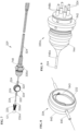
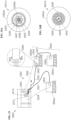
Figures 4A-4C are perspective, longitudinal cross-sectional, and exploded views, respectively, of the fiber optic termination ofFigure 3A . -
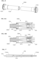
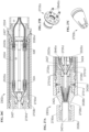
Figure 5 is a longitudinal, cross-sectional view of another version of the fiber optic termination ofFigure 4B . -
Figure 6 is a cross-sectional view of an entry portion of the fiber optic termination ofFigure 5 . -
Figure 7 is a perspective view of the fiber connection assembly ofFigure 4B . -
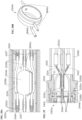
Figure 8 is a perspective view of a portion of the fiber storage base ofFigure 7 . -
Figure 9 is a perspective view of the integral manifold ofFigure 7 . -
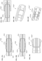
Figures 10A and 10B are longitudinal, cross-sectional view of the manifold portion of the fiber optic termination ofFigure 5 depicting example configurations of the integral manifold. -
Figures 11A and 11B are longitudinal, cross-sectional views of manifold portions of the fiber optic termination depicting additional example configurations of integral manifold integral manifold. -
Figures 12A and 12B are perspective and longitudinal, cross-sectional views, respectively, of the integral manifold. -
Figures 13A and 13B are perspective views of additional configurations of the fiber connection assembly with integral manifolds. -
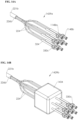
Figures 14A-14B are perspective views of more additional configurations of the fiber optic connection assembly including extended and cube manifolds, respectively. -
Figure 15 is a perspective view of a flexible hose. -
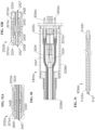
Figures 16A and 16B are longitudinal, cross-sectional views of a connector portion of the fiber optic terminations ofFigures 4B and5 , respectively. -
Figure 17 is a longitudinal, cross-sectional view of a fiber optic contact. -
Figures 18A-18G are cross-sectional views of hermetic tube joints positionable about the optical fibers. -
Figures 19A-19F are cross-sectional views of non-hermetic tube joints positionable about the optical fibers. -
Figures 20A and 20B are perspective views of fiber optic termination assemblies comprising a plurality of fiber optic terminations having a dedicated and a combined fiber storage chamber, respectively. -
Figure 21 is a flow chart depicting a method of assembling a protective fiber optic termination. -
Figures 22A and22B are flow charts depicting additional methods of assembling a protective fiber optic termination. -
Figure 23 is a schematic diagram depicting an equipment site with multiple equipment units, the equipment site having a multi-link communication system including sources, communication cables, and multi-link terminations. -
Figures 24A and 24B are cross-sectional views of example versions of multi-link cables suitable to be used with the fiber optic termination of the claimed invention. -
Figures 25A and 25B are schematic diagrams depicting example configurations of the fiber optic system ofFigure 23 with the multi-link termination in an electro-optical and processed configuration, respectively. -
Figure 26A is a longitudinal, cross-sectional view of an example electro-optical configuration of the multi-link termination ofFigure 25A , according to the claimed invention. -
Figure 26B is a longitudinal, cross-sectional view of an example processed-optical configuration of the multi-link termination ofFigure 25B , according to the claimed invention. -
Figure 26C is a longitudinal, cross-sectional view of an example electrical configuration of the multi-link termination, according to the claimed invention. -
Figure 27A is a cross-sectional view of an entry portion of the multi-link termination ofFigure 26A including a sealed connector with a multi-link retaining nut. -
Figure 27B is a perspective view of an outer portion of the multi-link retaining nut ofFigure 27A . -
Figure 27C is a perspective view of the inner portion of the multi-link retaining nut ofFigure 27A . -
Figure 28A is a cross-sectional view of a manifold and tube portion of the multi-link termination ofFigure 26A . -
Figure 28B is a perspective view of a mutli-link fiber storage base ofFigure 26B . -
Figure 29 is a cross-sectional view of a manifold portion of the multi-link termination ofFigure 26A . -
Figure 30 is a cross-sectional view of a connector portion of the multi-link termination ofFigure 26A having both optical and electrical contacts. -
Figure 31 is a longitudinal, cross-sectional view of the electrical contact ofFigure 30 . -
Figures 32A and 32B are cross-sectional views of the electrical tube joints ofFigure 26A . -
Figure 33 is a perspective view of another fiber optic termination assembly comprising a plurality of multi-link terminations. -
Figures 34A and34B are flow charts depicting methods of assembling a protective multi-link termination. - The description that follows includes exemplary apparatus, methods, techniques, and/or instruction sequences that embody techniques of the present subject matter. However, it is understood that the described embodiments may be practiced without these specific details.
- A termination for use in harsh environments, such as offshore underwater oil and gas fields, is provided. A "harsh environment" as used herein refers to any location where the disclosed termination may be used in which conditions may be damaging to the termination (or components thereof), communication cable, communication links carried by the communication cable (e.g., optical fibers, electrical wires, etc.), and/or other portions of the termination and/or equipment usable therewith. The harsh environment may include harsh conditions, such as damaging materials (e.g., corrosive or toxic materials and/or fluids (e.g., seawater, saline, etc.), chemicals (e.g., compositions that are either naturally present or disposed to ambient hydrogen from cathodic protection system and other gases), high pressure and temperature (e.g., above ambient), and/or other conditions that may lead to damage (e.g., functional performance degradation) of the termination, communication cable, and/or other portions of the termination and/or equipment usable therewith suddenly or over time.
- The termination includes a sealed housing, a connection assembly, and an equipment connector. The connection assembly may be, for example, a fiber connection assembly including a manifold to distribute links, such as optical fibers of a fiber optic cable, to optical contacts of the equipment connector. The termination may be a fiber optic and/or electrical termination configured to define a sealed chamber to maintain the optical fibers in a protected environment against ambient pressure. The termination may be used to provide a releasable connection to equipment, and/or a modular configuration capable of replacement of portions of the termination system in a sealed environment.
- The termination may be provided with modular and/or pressure balanced housings capable of receiving a variety of optical cables for connection to equipment. The termination may have redundant layers, such as housings, bladders, tubes, etc., to isolate the optical fibers from harsh conditions and house the optical fibers in their native environment and/or within a pressure balanced environment. The termination may also be provided with connectable features, such as a storage base, manifold, connector, and optical contacts, which permit pre-assembly of the cable for quick disconnect.
- The termination may be capable of operation in even harsh conditions and connectable in a variety of configurations for flexibility of use. The termination may be provided with modular features to enable pre-assembly and replacement of parts as needed. The termination may be configured to provide one or more of the following: protection of cables (e.g., isolation of optical fibers from harsh conditions), maintenance of communication links of the cables in its native environment at connection, housing of the communication links (e.g., optical fibers) where exposed for connection, prevention of degradation of the cable (e.g., optical fibers), sealing about exposed portions of the communication links (e.g., hermetically, redundantly, mechanically), distribution of the communication links for contact, reduced assembly size, efficient manufacture, usability with existing commercial components, manufacturing flexibility and efficiency, facilitation of assembly, storage of optical fibers, higher bandwidth, longer optical fiber communication distance, lower cost, reduction in electromagnetic interference, etc.
-
Figure 1 depicts an example environment in which various terminations, such as afiber optic termination 102, may be used. While anoffshore wellsite 100 is depicted, thefiber optic termination 102 may be used in a variety of applications, such as applications in any harsh or non-harsh environment. In the example shown, thewellsite 100 includessurface equipment 104 andsubsea equipment 106. Also, whileFigure 1 depicts afiber optic termination 102, other terminations disclosed herein may be used. - The
surface equipment 104 includes aplatform 108, arig 110, and asurface unit 112. Therig 110 may optionally be placed on an offshore vessel, an onshore rig site, or other location. Thesurface unit 112 may be an operator's facility including a central processing unit (CPU) and associated electronics (e.g., database, power, communication, control, and/or other devices). Thesurface unit 112 may also include asource 114 usable with thefiber optic termination 102 for communication about the wellsite. - The
subsea equipment 106 includes ariser 118,sea floor equipment 120, and afiber optic system 122 including thefiber optic termination 102. Theriser 118 extends from therig 110 to thewellbore 116 for passing fluid therebetween. Theriser 118 may have conduits (e.g., choke and kill lines) and/or other equipment usable therewith. - The
sea floor equipment 120 is positioned on thesea floor 115 about thewellbore 116 for performing wellsite operations. Thesea floor equipment 120 may include a variety of equipment, such as a blowout preventer, low riser marine package (LRMP), a production tree, subsea distribution, and/or other devices used for performing wellsite operations. - Communication couplings 124 may be provided about the
wellsite 100 for passing data, power, control, and/or other signals therebetween. Communication couplings may be provided with on or offsite locations for operating the various equipment. Thefiber optic system 122 may be usable as one or more of the communication couplings 124 for communication about the wellsite. Thefiber optic system 122 may be used to provide the communication coupling between the various equipment above the wellsite, such as thesea floor equipment 120 and/or thesurface unit 112, for passing data therebetween. Thefiber optic system 122 may be part of or separate from the communication couplings 124. - The
fiber optic system 122 includes one or morefiber optic cables 121 and/orfiber optic terminations 102. Thefiber optic system 122 may be coupled between thesource 114 and thesea floor equipment 120 for communication therebetween. Thefiber optic termination 102 may be positioned about (e.g., coupled to or positioned in) thesurface unit 112 and/or the sea floor equipment 120 (e.g., near or away from the wellbore, e.g., at subsea distribution equipment). Thefiber optic termination 102 may also be coupled to thesource 114 and/orother surface equipment 104 by thefiber optic cable 121 for operation therewith. Thefiber optic cable 121 may be connected between thesource 114 and thefiber optic termination 102 and/or between thesea floor equipment 120 and thefiber optic termination 102 for passing signals therebetween. - The
source 114 may have a laser to pass light through thefiber optic cable 121 for measuring wellsite parameters as described further herein. The CPU and/or electronics at thesurface unit 112 may be used for sending signals (e.g., command, control, etc.) and/or receiving signals (e.g., measured data) from thefiber optic system 122 and/or thesource 114. - The
fiber optic termination 102 may be a variety of devices capable of connecting thefiber optic cable 121 to the wellsite equipment for operation (e.g., communication) therewith. For example, thefiber optic termination 102 may be a conventional termination usable with loose tube type optical cables. At least some such conventional terminations may expose optical fibers from a tube of the fiber optic cable in a compartment maintained at atmospheric pressure. Examples of conventional terminations are provided inUS Patent/Application Nos. US4598290 ,US20140233898 ;US6796821 ,US4545645 ,US6584253 ,US6028974 ,US7338215 ,US4516830 , andUS5048921 . - In another example, the
fiber optic termination 102 may be a protective fiber optic termination provided with a housing having multiple barriers and sealed at atmospheric pressure. This protective fiber optic termination may be used to maintain a pressure within thetermination tubes 324 consistent with that within the optical cable, and may be positioned within layers of redundant barriers intended to prevent exposure of the optical fibers to conditions (e.g., harsh environment conditions) that may negatively affect the optical fibers. Pressure within the cable may be, for example, about 14.5 psi (1 Bar). -
Figures 2A and 2B are cross-sectional views of variousfiber optic cables 221a,b usable with thefiber optic system 122.Fiber optic cables 221a,b includeoptical fibers 222, one ormore cable tubes 224, and one ormore layers 226a-d. Thecable tubes 224 are positioned withinconcentric layers 226a-d. Theoptical fibers 222 are housed within thecable tubes 224. - As shown in the example of
Figure 2A , the fiber optic cable may be a 'loose tube'fiber optic cable 221a includingoptical fibers 222 floating in a gel withincable tube 224. The gel may be used to scavenge hydrogen to prevent deterioration of optical fibers and its ability to transmit light (e.g., hydrogen darkening). Theoptical fibers 222 may be protected within thecable tube 224 in the gel (or other fluid) at a given manufactured pressure (e.g., an atmospheric pressure of about 14.7 pounds per square inch (101.3 kPa). - As shown in the example of
Figure 2B , thefiber optic cable 221b may havemultiple cable tubes 224 withoptical fibers 222 floating therein. Thecable tubes 224 may be helically disposed within thelayers 226a-d. - As shown in
Figures 2A and 2B , theoptical cables 221a,b have multipleconcentric layers 226a-d disposed around the tube(s) 224.Layer 226d is an insulation layer disposed around the tube(s) 224.Outer layer 226a surrounds theinsulation layer 226d. Armored (e.g., steel)wires 225 are provided along an outer surface of theinner layer 226b. Anouter insulation layer 226c is positioned betweenouter layer 226a andinner layer 226b. While a specific configuration of examplefiber optic cables 221a,b are shown, various configurations of one ormore layers 226a-d and/or other features, such as armored wires, jackets, sheaths, insulation, and/or other features, may be provided to house and protect theoptical fibers 222. - While
Figures 2A and 2B show example versions of a 'loose tube' concentric and coaxial fiber optic cable, other versions may be used, such as a tight buffer cable with a single fiber therein. The cable may have various features, such as one or more optical fibers within one or more tubes, a circular or non-circular cross section, one or more layers about one or more of the tubes, gel and/or other substance to support the optical fibers in the tubes, maintained pressure within the tubes. Examples of various fiber optic cables that may be used are commercially available from GENERAL CABLE™ at www.generalcable.com. -
Figures 3A and 3B are schematic diagrams depicting thefiber optic system 122 ofFigure 1 in greater detail. As shown in these views, thefiber optic termination 102 includes a fiberoptic housing 328, afiber connection assembly 329, andconnector 335. Thefiber optic housing 328 has apassage 327 therethrough to receive the fiber optic cable 121 (which may be in the form ofcables 221a,b ofFigures 2A,2B ) at one end and connects viaconnector 335 at an opposite end to equipment (e.g., the sea floor equipment 120). - The
fiber optic cable 121 extends into one or moresealed chamber 331 alongpassage 327 of thehousing 328 where it is stripped of its outer layers to expose thecable tube 224. Thecable tube 224 is connected to thefiber connection assembly 329 to distributeoptical fibers 222 for connection to thesea floor equipment 120. Thefiber connection assembly 329 provides a sealed container about the exposed portions of the fiber optic cable 121 (e.g., thecable tubes 224 and/or optical fibers 222). These exposed portions may be protectably sealed within thechamber 331 of thehousing 328. The sealedchamber 331 may be filled with the gel (or other fluid) maintained under pressure. The gel may be similar to the gel in the fiber optic cable maintained at a similar pressure or pressure balanced to ambient pressure. - The
fiber connection assembly 329 is positioned within thefiber optic housing 328 and is disposed about exposed portions of thefiber optic cable 121 to provide sealing protection thereabout. Thefiber connection assembly 329 includes one ormore termination tubes 324, astorage base 334, and a manifold 330 for receiving and distributingoptical fibers 222. Thefiber connection assembly 329 is sealable about the exposed portions of thefiber optic cable 121 to create a redundant sealed layer thereabout. Thefiber connection assembly 329 also provides a second container within which theoptical fibers 222 may be exposed for connection to wellsite equipment. - The
termination tubes 324 are tubular members disposable about exposed portions of thefiber optic cable 121 to seal thereabout. While depicted as being circular tubes with a central passage therethrough, thetermination tubes 324 may be of any shape. Thetermination tubes 324 may receive the exposedcable 121 therethrough and seal (e.g., hermetically or non-hermetically) to the exposedoptical cable 121. Thesetermination tubes 324 may receive thecable tube 224 and/oroptical fibers 222 therethrough. Thetermination tubes 324 may be located about the exposed portions of theoptical cable 121, for example, between thecable tube 224 and thestorage base 334, between the storage base and the manifold 330, and/or between the manifold 330 and theoptical contacts 336. - Tube joints 323 may be provided about the
fiber optic cable 121, thetermination tubes 324 and/or portions of thefiber connection assembly 329 to seal portions thereof. For example, tube joints 323 may adjoin a portion of thefiber optic cable 121 to atermination tube 324 for sealing connection together. Thetermination tubes 324, tube joints 323, and/or portions of thefiber connection assembly 329 may be attached to or integral therewith. - The
termination tubes 324 may be, for example, seamless straight tubes and/or flexible tubes capable of sealing operation in thetermination 102. Thetermination tubes 324 may be provided with flexibility by, for example applying a pattern (e.g., longitudinal geometric pattern) on the tube (e.g., using a metal forming processes). In an example, the termination tubes may be seam welded tubes. - Various lengths of
termination tubes 324 may be used and staggered along the length of portions of thefiber optic cable 121. Optical epoxy may be applied for a predetermined length to fill the space betweenoptical fiber 222 and an inner surface of the tube joint 323 to adjoin thetermination tubes 324 to the tube joints 323 and/or to portions of the components of thetermination 102, such as the manifold 330 and/orstorage base 334, and cured thereto. Upon curing, the epoxy may sealingly engage with theoptical fibers 222 and jumper thetermination tube 324. - The
storage base 334 receives a length of the exposed portion of thefiber optic cable 121 from one ormore termination tubes 324. Thestorage base 334 allows for a length of theoptical fibers 222 to be enclosed therein so that a necessary length ofoptical fibers 222 is present to provide the needed length for splicing operations as is described further herein. The exposed portions of thefiber optic cable 121 extend through thestorage base 334 and to the manifold 330 via the termination tube(s) 324. - The manifold 330 receives the exposed portions of the
fiber optic cable 121 at one end and passes them through distribution paths in themanifold 330. The distribution paths extend through the manifold 330 for distributing one ormore cable tubes 224 and/oroptical fibers 222 for connection withoptical contacts 336 ofconnector 335. The manifold 330 may have various configurations as described further herein. - The
cable tubes 224 and/oroptical fibers 222 pass from the distribution paths to theoptical contacts 336 via thetermination tubes 324. -
Connector 335 hasoptical contacts 336 on an end thereof receivable by acorresponding plug 338 of thesea floor equipment 120. Theoptical fibers 222 pass through thetermination tubes 324 and are coupled to theoptical contacts 336 for communication therewith. As shown byFigure 3B , thetermination 102 may be modular for connection and/or disconnection as is described further herein. - The termination may be a modular or unitary device. The components of the
termination 102 may be replaceable, for example, for maintenance and/or repair. Additional connectors and/or other portions of thetermination 102 may be modularly provided along the termination to vary a length of components of thefiber optic termination 102. Part or all of the components of the termination may be rigid and/or flexible. -
Figures 4A-4C are perspective, cross-sectional, and exploded views, respectively, of thefiber optic termination 102.Figure 4B is a cross-sectional view of the fiber optic termination ofFigure 4A taken alongline 4B-4B. Some internal portions are in cross-section for descriptive purposes. As shown in this view, thehousing 328 defines apassage 327 therethrough and the sealedchambers 331a-c therein for receiving thefiber optic cable 121 therein. - The
housing 328 may be provided with one or more layers and/or chambers to seal theoptical cable 121 as it is exposed within thehousing 328. Thehousing 328 may be sealed such that the sealedchamber 331 defines a waterproof environment isolated from exposure to external (e.g., harsh) conditions. The chamber(s) may be pressure balanced to maintain pressure (e.g., atmospheric or ambient pressure) therein. Thehousing 328 may be filled with a fluid to maintain a pressure balance within thehousing 328 to support theoptical fibers 222 within theoptical cable 121. The pressure may be maintained, for example, to prevent pressure to the termination and/or optical cables when thetermination 102 is deployed to subsea locations at increased pressure. - The
housing 328 may be a unitary or modular container made from materials capable of, for example, withstanding various operations, such as assembly, handling, installation and/or in-service loading (e.g., loading from the harsh environment), corrosion resistance (e.g., to sea water), and/or compatibility with the operating environment and/or other components in physical and/or electrochemical contact with the housing. - The
housing 328 may be made of a variety of materials, such as metallic, plastic, alloy, and/or other materials (e.g., stainless steel, nickel, chromium, titanium, polymer, plastic, nylon, PEEK, ABS, PE, PET, PBT, PTFE, PEI, and/or other materials of various grades). Example materials include corrosion resistant metal alloys (e.g., super duplex stainless steel alloys, titanium alloys, nickel and chromium based alloys and/or austenitic stainless steel alloys, cathodic protected metals, etc.) and/or nonmetallic materials (e.g., thermoplastics, engineering plastics, polymers, Nylon, ABS, PE, PET, PBT, PTFE, PEI, PEEK, etc.), and/or rigid composites (e.g., metallic or nonmetallic materials). Coatings, corrosion protection, and/or other materials may be applied or integrated into the housing. - As shown in the example of
Figures 4A-4C , thehousing 328 of thefiber optic termination 102 may include modular portions, such as anentry housing 328a, atube housing 328b, a manifold housing (or tube) 328c, aflexible housing 328d, and aconnector housing 328e. Theentry housing 328a includes a taperedportion 430a and a sealedconnector 430b. The taperedportion 430a is coupled to an entry end of thetube housing 328b by the sealedconnector 430b and ahousing seal 429. A larger end of the taperedportion 430a receives a portion of the sealedconnector 430b. The taperedportion 430a and the sealedconnector 430b are aligned to receive thecable 121 therethrough. Further details about theentry housing 328a are described further herein with respect toFigure 6 . - The
tube housing 328b is positioned between theentry housing 328a and themanifold housing 328c. Thetube housing 328b receives a portion of the sealedconnector 430b in its entry end. As shown, the sealedconnector 430b extends a distance into the one end of thetube housing 328b and anintegral manifold 330a extends into an opposite end of thetube housing 328b and defines a sealedchamber 331a therebetween. Theintegral manifold 330a may be rigidly connected to taps in thetube housing 328b. - The
manifold housing 328c is sealingly coupled between thetube housing 328b and theflexible housing 328d. Theintegral manifold 330a may include a sealed interface (e.g., o-ring seal) for sealing engagement between thetube housing 328b and themanifold housing 328c. Themanifold housing 328c has a portion of theintegral manifold 330a extending into one end and a portion of theflexible housing 328d extending into an opposite end thereof to define the sealedchamber 331b therein. - The
manifold housing 328c may be coupled to theintegral manifold 330a and to thetube housing 328b by various connection means, such as press fit, bonding, threading, clamping, crimping, fastener, and/or other means. For example, themanifold housing 328c may be coupled to thetube housing 328b by theintegral manifold 330a, which may act as a sealed connector therebetween. - The
flexible housing 328d is sealingly coupled at one end to themanifold housing 328c and at an opposite end to theconnector housing 328e. Theflexible housing 328d may be rigidly connected to taps in thehousing flexible housing 328d for sealing connection with themanifold housing 328c and theconnector housing 328e. In this version, theconnector housing 328e is integrally connected to theconnector 335. - Each
housing 328a-e is a hollow tubular or non-tubular member with thepassage 327 therethrough shaped to receive thecable 121 and thefiber connection assembly 329 used therewith. An entry end of the taperedportion 430a of theentry housing 328a is shaped to receive thecable 121 therein. Thefiber optic cable 121 extends into the sealedconnector portion 430b where anouter layer 226a and armored wires 225 (as inFigs. 2A, 2B ) of thecable 121 are stripped away. Theinner layer 226b is stripped away in the sealedconnector 430b to reveal the inner cable tube(s) 224 with theoptical fibers 222 therein. - The
cable tube 224 extends from the sealedconnector 430b into afirst chamber 331a in thetube housing 328b. Thetermination tubes 324 are connected to the exposedcable tubes 224 by a tube joint 323 and receive thecable tubes 224 and/or theoptical fibers 222 therethrough. The optical fibers 222 (with or without the cable tubes 224) within thetermination tubes 324 extend through thehousing 328. Theoptical fibers 222 are supported in themanifold housing 328c,flexible housing 328d and to theconnector housing 328e by thetermination tubes 324. - The
termination tubes 324 carrying thecable tube 224 connect to thestorage base 334 and theintegral manifold 330a to pass theoptical fibers 222 therethrough. As shown, thecable tube 224 may extend from thetermination tubes 324, through thestorage base 334, through another set oftermination tubes 324 and into theintegral manifold 330a. Thecable tube 224 extends through distributor paths of the manifold and into another set oftermination tubes 324. Asecond chamber 331b may be defined in themanifold housing 328c, andflexible housing 328d. Theconnector housing 328e defines another fluidtight chamber 331c about thefiber optic cable 121. - The
termination tubes 324 also extend from theflexible housing 328d and to theoptical contacts 336 in theconnector housing 328e. Theoptical fibers 222 are protected within thefiber connection assembly 329 as they pass through thehousing 328 to theconnector 335 for connection viacontacts 336 to theplug 338 of the equipment (e.g.,sea floor equipment 120 ofFigures 3A and 3B ). - The
optical contacts 336 extend into theconnector housing 328e to directly receive thetermination tubes 324 containing thecable tubes 224 and theoptical fibers 222. Theoptical fibers 222 may be exposed within thetermination tubes 324 of the connector housing for optical coupling within theoptical contacts 336. Theoptical fibers 222 are optically coupled to the equipment via a connection between theoptical contacts 336 and thecorresponding plug 338 of the equipment (e.g., sea floor equipment 120 (Figures 3A, 3B )). - The
housing 328 may have one or more sealedchambers 331 defined therein alongpassage 327 extending through thehousing 328. As shown, thehousing 328 has thechambers 331a-c defining water tight and pressure secure chambers about thefiber connection assembly 329 with the exposed portions of thecable 121 protectively housed therein. The chambers may be surrounded by one or more layers and/or bladders. As shown, thechamber 331a may have abladder 435 therein made of a tubular or non-tubular flexible material (e.g., elastomer) that may be stretched in the radial direction as needed. Thebladder 435 lines thetube housing 328b between the sealedconnector 430b and theintegral manifold 330a to define a fluidtight chamber 331a therein. Thebladder 435 may be secured in place between theintegral manifold 330a, the sealedconnector 430b and thetube housing 328b by a retainer ring, plates, and/or other devices. Thebladder 435 may have a fluid source to maintain fluid pressure therein as is described further herein. -
Figure 5 shows another cross-sectional view of thefiber optic termination 102 ofFigure 4A taken at a different angle along line 5-5. Thefiber optic termination 102 has been modified to define a modified fiber optic termination 102' with a modified connection assembly 329'. As shown in this view, the modifiedconnector housing 328e' may optionally be modular as is described further herein. - As also shown in this view, the
bladder 435 in thetube housing 328b is supported byplates 533 and the manifold has thedistribution paths 532 therethrough. Thefiber storage base 334 may be secured in place in thetube housing 328b by a plastic or metallic bushing and/or by a fastener connected to thestructural plates 533. - While a specific configuration is provided, various combinations of one or more housings, connectors, seals, and/or other features may be provided to protect the
fiber optic cable 121, thefiber optic system 122, and/or its components. The housing(s) 328 may include rigid and/or flexible portions as needed to facilitate assembly, removal, maintenance, operation, and/or other needs. Thehousing 328 may also be provided with other features, such as taps therethrough to receive fasteners, and/or holes to provide passage for the free flooding of ambient fluid (e.g., sea water) to flow around the external surface of thebladder 435. Fluid may be flooded in thehousing 328, for example, to provide pressure balancing of thechamber 331a. -
Figure 6 shows anentry portion 6 of the fiber optic termination ofFigure 5 in greater detail. Thefiber optic cable 121 is sealingly engageable with the taperedportion 430a upon entry therein. The material of theentry housing 328a may be sealingly engageable with an outer surface of thefiber optic cable 121. For example, theentry housing 328a may be made from an elastomeric material (e.g., rubber, thermoplastic, thermoplastic elastomer, etc.) sealingly engageable with the outer layer of thecable 121. The diameter and length of theentry housing 328a may be defined to facilitate sealing therebetween.. - Sealing about the
fiber optic cable 121 may also be provided by various portions of thehousing 328 and/or seals (e.g., seal 429 ofFig. 4B ,5 ). Theentry housing 328a may be configured to provide an entry seal against the ambient pressure of the environment. The fiber optic cable, housing, seals, fiber connection assembly, and/or portions thereof may be made of materials that provide sealing engagement therebetween. In at least some cases, such features may stretch and/or respond to pressure (e.g., deform) to facilitate sealing engagement therebetween. - The housing may also be provided with seals (e.g., seal 429 of
Fig. 4B ,5 ) for sealing with thecable 121. Theseal 429 may be, for example, a ring-shaped backup seal having a cylindrical body receivable within theconnector portion 430b of the entry housing in an annular space between an outer surface of thefiber optic cable 121 and theentry housing 328a. - As shown in this view, sealed
connector 430b has atip 637a, atapered shaft 637b, and anend 637c with a passage to receive theoptical cable 121 therethrough. Thetip 637a is receivable into the taperedportion 430a of theentry housing 328a. A seal ring (e.g., housing seal 429) may optionally be provided in thetip 637a to sealingly engage theoptical cable 121. Seals may be provided about theouter sleeve 639b for sealing engagement therebetween. - The tapered
portion 637b extends between theentry housing 328a and thetube housing 328b, and is receivable in theend 637c (e.g., by threading). Theend 637c has aninner sleeve 639a, anouter sleeve 639b, and an extension sleeve 639c. Theouter sleeve 639b is receivable along the inner surface of thetube housing 328b. Theinner sleeve 639a is receivably supported within theouter sleeve 639b, and has a passage to receive portions of thecable tube 224 therein. The extension sleeve 639c extends from an end of theinner sleeve 639a within an end of theouter sleeve 639b. A retaining nut 639d may optionally be connected about thesleeves 639a-c to secure the sleeves in position. - As shown, the sealed
connector 430b may have one or more portions shaped to receive portions of theoptical cable 121 as they are stripped to expose thetube 224 containing theoptical fibers 222. Theinner sleeve 639a may sealingly engage theinner layer 226b and thetube 224 as they are exposed from thecable 121. Theinner sleeve 639a may have a shape to receive thecable 121 and have a step to receive the outer diameters of portions thereof. - The
outer layer 226a of thecable 121 may be stripped such that thearmored wires 225 are exposed within the sealedconnector 430b. Thearmored wires 225 are spread to provide mechanical support to thecable 121. Thearmored wires 225 are disposed about a tapered portion of theinner sleeve 639a to axially retain thecable 121 in place against longitudinal pulling away. A retention material (e.g., a matrix formed from a potting compound, such as a two part wire rope termination chemical) may optionally be placed about the armored wires to secure them in place between thesleeve 639a and the sealedconnector 430b. - The exposed
cable tube 224 extends from theinner sleeve 639a and through the extension sleeve 639c and the retaining nut 639d. The exposedcable tube 224 extends into thefiber connection assembly 329 as it passes through the remainder of the termination (not shown in this figure).Optical fibers 222 are protectively maintained within thecable tube 224 and/or thefiber connection assembly 329. Theoptical fibers 222 may optionally pass through thefiber connection assembly 329 with or without thecable tube 224 thereabout. - As also shown in this view, the
bladder 435 may be filled by a fluid. Theouter sleeve 639b has afluid conduit 639 therethrough alignable with a port through thetube housing 328b. Fluid (e.g., oil, glycol, de-ionized water, grease, gel, and/or other compatible fluid) may be provided inchamber 331a. Thefluid conduit 639 may be used to fill thechamber 331a (and other chambers) with fluid. - A valve is optionally provided therein to selectively allow fluid exchange between the
chamber 331a and an exterior of thehousing 328. The fluid filledchamber 331a may be sealed from ambient pressure by a plug that is in sealing engagement withchamber 331a. The plug may have an o-ring seal and be retained in place by a retaining ring. When the ambient pressure of the environment is experienced by thebladder 435, the bladder may flex under the ambient pressure until pressure in thebladder 435 is equalized with the pressure outside of thehousing 328. -
Figure 7 is a perspective view of an example configuration of thefiber connection assembly 329. Thefiber connection assembly 329 is depicted as being removed from thehousing 328 to show its components in greater detail. As shown by this view, thefiber connection assembly 329 may have various configurations for protectively housing the exposed portions of thecable 121 as it passes through thetermination 102. As shown by these views, thefiber connection assembly 329 includes various components sealingly enclosed about the exposedcable 121 to provide a second layer of protection about thecable tubes 224 andoptical fibers 222 within thehousing 328. - The
fiber connection assembly 329 as is shown inFigure 7 includes thestorage base 334, theintegral manifold 330a, and thetermination tubes 324 for receiving optical fibers from the exposedoptical cable 121. Theoptical fibers 222 are protectively maintained within thetermination tubes 324 in their natural environment surrounded by gel. Thetermination tubes 324 may be connected to thestorage base 334, theintegral manifold 330a, and/or other tubular connections by mechanical bundling aids, such as equally spaced tray and tape. - The
outer layer 226a of theoptical cable 121 is stripped back to expose thearmored wires 225 andinner layer 226b. Theinner layer 226b is stripped back to expose thecable tube 224. The termination tube(s) 324 are sealingly connected to thecable tube 224 to receive thecable tube 224 and/oroptical fibers 222 therethrough. - The
optical fibers 222 are passed from theoptical cable 121 into thestorage base 334 and theintegral manifold 330a via thetermination tubes 324. Thetermination tubes 324 extend fromcable tube 224 to thestorage base 334, from thestorage base 334 to theintegral manifold 330a, and from theintegral manifold 330a to the connector 335 (not shown). Thetermination tubes 324 may be integrally formed with or connectable to thestorage base 334,integral manifold 330a, theconnector 335, and/or other components of thetermination 102. - As also shown in this view, the
cable tube 224 extends from theinner layer 226b, through thestorage base 334 and into theintegral manifold 330a. Thecable tubes 224 and/oroptical fibers 222 are dispersed through theintegral manifold 330a and out a plurality ofoutlets 748 of theintegral manifold 330a. Thecable tubes 224 and/oroptical fibers 222 pass through thetermination tubes 324 to certain optical contacts ofconnector 335 for optical connection therewith. - The tube joints 323 are also provided to connect the
termination tubes 324 tocable tubes 224,other termination tubes 324, and/or other components (e.g.,storage base 334,integral manifold 330a, etc.). The tube joints 323 may be discrete tubular seals that receivably seal about the various portions of thefiber optic cable 121 and thefiber connection assembly 329 to provide a seal thereabout. - The
termination tubes 324 andtube joints 323 may be made of various materials, such as elastomers and/or plastics sealable with the various portions of thefiber optic cable 121 and/or various portions of the fiber connection assembly 329.Thetermination tubes 324 may be identical to the cable tubes 224 (Figures 2A and 2B ). -
Figure 8 shows thefiber storage base 334 in greater detail. A cover of thestorage base 334 has been removed to reveal achamber 843 therein. Thestorage base 334 is positionable in thehousing 328 for hosting a length of theoptical fibers 222 therein. - The
fiber storage base 334 may have a circular,rigid body 842 to protect the optical fibers therein. The body 842 (and/or cover) may have a shaft portion and a shoulder collar with at least one groove along an outer surface thereof to accommodate a seal.Tubular arms 840 may extend radially from opposite sides of thebody 842. Theoptical fibers 222 may extend through thetubes 324 and thetubular arms 840 into thechamber 843 defined within thecircular body 842. - As needed, a length of the
optical fibers 222 may be provided for operation with the fiber optic system described herein. Theoptical fibers 222 may be spliced together using, for example, optical fusion splicing. The splicedoptical fibers 222 stored inside thefiber storage base 334 may be surrounded by gel. Theoptical fibers 222 may be coiled and held inside the chamber prior to use. Gel may be added to fill up the space beyond thecable tube 224 that contained the same gel and/or to maintain the optical fibers at pressure. The cover (shown inFigures 4B ,5 , and7 ) is positionable over thecircular body 842 to sealably contain theoptical fibers 222 therein. - The
tubular arms 840 may be rigid or flexible tubular supports to receivingly support theoptical fibers 222 therein. Thetubular arms 840 may abuttingly engage thecable tube 224 and/ortermination tube 324 to maintain a seal about theoptical fibers 222 extending therethrough. This abutting engagement may be provided on one or both sides of thefiber storage base 334. Tube joints 323 may also be provided. - The
storage base 334 and/ortubular arms 840 may be made from various materials, such as stainless steel alloys, copper alloys, and thermoplastic (e.g., PEI or PEEK). Thetubular arms 840 may also be made out of elastomeric tubing, such as surgical tubing. Thetubular arms 840 may be integrally formed with thebody 842, or secured thereto by laser beam welding, welding, ultrasonic welding, electron beam welding, brazing, soldering, and/or other connection method and/or means. Portions of thefiber storage base 334 may be joined, for example, using laser beam welding, welding, ultrasonic welding, electron beam welding, brazing or soldering. In another example, an elastomeric suction cup seal may be stretched over thefiber storage base 334 to enclose it therein. - The
fiber storage base 334 may be provided with additional features. Optionally, a spool may be provided in thestorage base 334 for coiling theoptical fibers 222 therein. Hermetic and/or non-hermetic seals may be provided about a periphery of the body, between the cover and the body, and/or between the arms and the tubular connections. "Hermetic" as used herein refers a seal that is fluid (or air) tight. To prevent passage of the fluids past the seal. - While the
storage base 334 is shown in thehousing 328b, it will be appreciated that one ormore storages bases 334 may be positioned in various locations about thetermination 102, such as in themanifold housing 328c. -
Figures 9-12B show various configurations of manifolds usable with the fiber optic terminations ofFigures 4A - 5 .Figure 9 is a detailed view of theintegral manifold 330a ofFigure 7 in a sealed configuration.Figure 10A is a cross-sectional view of aportion 10A of thetermination 102 ofFigure 5 depicting theintegral manifold 330a.Figure 10B is a cross-sectional view of a modified version of theintegral manifold 330a'. Theintegral manifold 330a is used to route theoptical fibers 222 from thefiber optic cable 121 tooptical contacts 336 of the connector 335 (see, e.g.,Figure 4B ). - The
integral manifold 330a includes amanifold base 942, amanifold cover 944, and adistributor 946. Themanifold base 942 is a ring-shaped member with themanifold cover 944 on one end and thedistributor 946 supported therein. - An outer surface of the
integral manifold 330a may be provided with threading or other connection means to sealingly secure theintegral manifold 330a in position. Themanifold base 942 may have an outer surface connectable to thetube housing 328b and themanifold housing 328c. An outer surface of themanifold cover 944 may have a profile for sealing engagement withbladder 435. This outer surface may be stepped for interface with portions of thetube housing 328b. The outer surface of themanifold cover 944 may be connected between thetube housing 328b and themanifold housing 328c. As shown inFigures 4B and5 , seals 429 may also be provided. - The
manifold cover 944 may sealingly engage thetermination tube 324 at the inlet end to receive theoptical fibers 222 therefrom. Themanifold cover 944 is a funnel-shaped member with aninlet 948a tapered to sealingly engage thetermination tube 324 and receive theoptical fibers 222 therethrough. Thecover 944 abuttingly engages themanifold base 942. A base end of themanifold cover 944 is connectable to themanifold base 942 by various connection means. - The
integral manifold 330a may be filleted to provide a transition for protecting the routed optical fibers 222 (e.g., from detrimental abrasion and stress concentration). This transition may be provided between themanifold cover 944 and thedistributor 946. Thedistributor 946 is a solid member receivable in themanifold cover 944 and supported by themanifold base 942. Thedistributor 946 defines thepath 532 for distributing theoptical fibers 222 through theintegral manifold 330a. Thepath 532 is a tubular channel defined between an internal surface of themanifold cover 944 and an outer surface of thedistributor 946. - The
path 532 may extend from theinlet 948a tooutlets 948b at an outlet end of theintegral manifold 330a. Thepath 532 may be arranged (e.g., at a predefined pitch circle diameter) for space distribution of theoptical fibers 222 through thetermination 102. Thepaths 532 may be stepped with various diameters as useful to convey thecable tubes 224 and/oroptical fibers 222 therethrough. - The
distributor 946 has a plurality ofoutlets 948b extending axially from an outlet end thereof, and shaped to pass a portion of theoptical fiber 222 therethrough. Theoutlets 948b are connectable totermination tubes 324 that extend from theintegral manifold 330a for connection to theconnector 335. Thefiber outlets 948b may be spaced about thedistributor 946 for connection with the optical contacts 336 (Figure 4A ). Thefiber outlets 948b may be positioned in alignment with theoptical contacts 336 with theoptical fibers 222 extending linearly therebetween. - The
termination tubes 324 may be hermetically joined to theinlet 948a and/oroutlets 948b of theintegral manifold 330a. Thetermination tubes 324 may be coupled to, or integrally formed with, theintegral manifold 330a. Theoptical fibers 222 may be distributed out theoutlets 948b and into thetermination tubes 324 under the protection of the tube joints 323. - The
integral manifold 330a may be provided with various features and/or variations.
Themanifold cover 944 may be integrally formed or sealed to themanifold base 942. As shown inFigure 10A , themanifold cover 944 may have an end positioned adjacent to themanifold base 942 in abutting engagement therewith. As shown by the modified version of theintegral manifold 330a' ofFigure 10B , a portion of the modified cover 944' may optionally be received into the modified manifold base 942' with a seal therebetween. The modified manifold cover 944' may have a stepped end receivable into an adjacent end of the modified manifold base 942'. The modified manifold cover 944' and the modified manifold base 942' may be provided with matable ends for mating connection therebetween. A seal may be provided therebetween for sealing engagement between the manifold base 942' and cover 944'. The modified manifold 330a' may have a modified distributor 946' therein. - The
integral manifold 330a, a' may be formed from a single component from manufacturing process, such as casting, or formed of separate components joined together permanently or temporarily (e.g., by bonding or fasteners). Theintegral manifold 330a,a' may provide a hermetic or non-hermetic seal about the optical fibers. Additional seals (e.g., o-rings) may be provided. Theintegral manifold 330a,a' may be dimensioned with a desired thickness and shape for operation in thetermination 102. -
Figures 11A-11B show additional versions of aplate manifold separate manifold 330c in a radially compliant configuration. In this version, theplate manifold 330b includes a modifiedmanifold base 942b andmanifold cover 944b. In place of thedistributor 946, theseparate manifold 330c is coupled to themanifold cover 944b adjacent the hole to receive and distribute theoptical fibers 222 therethrough. - The
manifold cover 944b is a circular plate receivable in an end of themanifold base 942b. Theplate cover 944b has a hole to receivingly engage thetermination tube 324 through this hole. Thetermination tube 324 may be in sealing engagement with themanifold cover 944b by a seal. Themanifold base 942b also has an opening therethrough. Themanifold cover 944b closes an inlet end of themanifold base 942b. The external surface of themanifold base 942b is positionable in sealing engagement with thetube housing 328b and themanifold housing 328c. - The
separate manifold 330c is receivable in an outlet end of themanifold base 942b.Termination tubes 324 extending through theplate cover 944b are coupled directly to theseparate manifold 330c to pass theoptical fibers 222 therethrough. Theseparate manifold 330c haspaths 1132 to distribute theoptical fibers 222 therethrough. Thetermination tube 324 extends through themanifold cover 944b and is coupled to theseparate manifold 330c. Theoptical fibers 222 are dispersed through theseparate manifold 330c. Tube joints 323 may be provided along thetermination tubes 324 to connect sections of thetermination tubes 324 and/oroptical fibers 222 passing therethrough. - As shown by
Figure 11B , a modifiedmanifold cover 944b' may be provided. In the example shown, themanifold cover 944b' has multiple concentric holes therethrough, with theseparate manifold 330c threaded through themanifold cover 944b'. As shown, one or more holes may be provided in themanifold cover 944b' to define a conduit for fluid exchange between thehousing chamber 331a and themanifold chamber 331b. In this version, the fluid filled in therespective chambers 331a,b is the same. -
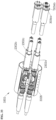
Figures 12A and 12B shows additional views of theseparate manifold 330c. As shown in these views, theseparate manifold 330c hasinlet tubes 1148a at an inlet end to receive thetermination tubes 324 andoutlet tubes 1148b to pass theoptical fibers 222 therethrough with thepath 1132 therebetween. Theoutlet tubes 1148b extend from the body of theseparate manifold 330c to define extended passages to pass theoptical fibers 222 therethrough. Theoutlet tubes 1148b may be in the form of tubular chambers with webbing therebetween extending axially from the body. The inlet andoutlet tubes 1148a,b in this version are integral with the body of theseparate manifold 330c, but optionally may be coupled thereto.Termination tubes 324 may be coupled to theoutlet tubes 1148b and sealed therewith to pass theoptical fibers 222 therethrough. -
Figures 13A - 14B show additional configurations of multi-layerfiber optic assemblies 1329a,b and 1429a,b, respectively. Thefiber optic assemblies 1329a,b ofFigures 13A-13B are used with thestorage base 334. Thefiber optic assemblies 1429a,b ofFigures 14A-14B are used without thestorage base 334. - The
fiber optic assembly 1329a ofFigure 13A is similar to thefiber optic assembly 329 ofFigure 7 , except that eachtermination tube 324 exiting theintegral manifold 330a is received by theseparate manifold 330c to distributeoptical fibers 222 therethrough. This provides for distribution of a portion of theoptical fibers 222 through theintegral manifold 330, and a second distribution of each of these portions ofoptical fibers 222 into subsets via theseparate manifolds 330c. As shown, theseparate manifolds 330c are the same distance from theintegral manifold 330a to provide a parallel arrangement of secondary distribution. - The
separate manifold 330c may be used in series to cascade and distribute theoptical fibers 222 of thefiber optic cable 121. Thecable tube 224 may be terminated to thefiber storage base 334, and then to theintegral manifold 330a. As shown inFigure 13A , thetermination tubes 324 of theintegral manifold 330a may be terminated to theseparate manifold 330c in series to theintegral manifold 330a and in parallel to each other. Themanifold 330a includes fouroutlets 948b integrally formed at the outlet end thereof. Accordingly, theintegral manifold 330a is terminated to separatemanifolds 330c that are in series with theintegral manifold 330a, whileseparate manifolds 330c are in parallel to each other. - The fiber optic assembly of Figure 1329b of
Figure 13B is similar to thefiber optic assembly 329 ofFigure 11A , except that one of thetermination tubes 324 exiting theseparate manifold 330c passes into a secondseparate manifold 330c to distributeoptical fibers 222 therethrough. As shown inFigure 13B , thetermination tubes 324 may be connected in series by theseparate manifolds 330c. Theseseparate manifolds 330c are connected to an end of the previousseparate manifold 330c. -
Termination tubes 324 may join therespective manifolds 330a-c. As inFigure 13A , this secondseparate manifold 330c provides a further distribution of theoptical fibers 222 from thetermination tube 324. In this version, theseparate manifolds 330c are in series along thefiber connection assembly 1329b. Theseseparate manifolds 330c may be terminated atintegral manifolds 330a and/or connect to theconnector 335. -
Figures 14A-14B show example versions of afiber connection assemblies 1429a,b usable with the multi-tubefiber optic cable 221b ofFigure 2B . In thefiber optic assemblies 1429a,b ofFigures 14A-14B , thetermination tubes 324 pass directly intoseparate manifolds 330c from theoptical cable 221b without passing through a storage base. InFigure 14A , upon exposure of theinner layer 226b of thefiber optic cable 221b, eachcable tube 224 is covered withtermination tubes 324 separated for entry into individualseparate manifolds 330c. As inFigure 13A , the separate manifolds are parallel and further distribute theoptical fibers 222. As also shown by this example, theseparate manifolds 330c are provided with inlet andoutlet tubes 1148a,b. - As shown in
Figure 14A , theseparate manifolds 330c may be in a parallel configuration in direct connection tomultiple cable tubes 224 of thefiber optic cable 221b. Each of thecable tubes 224 extend from thefiber optic cable 221b and are terminated to separatemanifolds 330c.Termination tubes 324 separate from and/or integral with theseparate manifolds 330c may be provided. In this example, theoptical fibers 222 are routed from thefiber optic cable 221b via theseparate manifolds 330c and directly terminated to theoptical contacts 336 of the connector 335 (see, e.g.,Fig. 4A ,5 ). - In the version of
Figure 14B , adedicated fiber storage 1434 may be used to distributecable tubes 224 of afiber optic cable 221b. Thecable tubes 224 pass throughtermination tubes 324 and thefiber storage 1434. As shown inFigure 14B , adedicated fiber storage 1434 may be utilized to receive thecable tubes 224 of thecable 221b. In this example, theoptical fibers 222 from thecable tubes 224 may be spliced to optical fibers connectable to theoptical contacts 336 and maintained inside thededicated fiber storage 1434 in a gel. As inFigures 13A and14A , theseparate manifolds 330c receive thecable tubes 224 and distribute theoptical fibers 222 therethrough. -
Figure 15 is a detailed view of theflexible housing 328d. Theflexible housing 328d may be a tubular member, such as a flexible hose, for flexibly connecting themanifold housing 328c andconnector housing 328e. Each end of theflexible housing 328d may include aflex connector 1555 receivable in the manifold andconnector housings 328c,e. Theflex connector 1555 may include a fitting, crimp sleeve, seals and/or other features to sealingly engage the adjacent housings. - A
flexible hose 1556 extends between theflex connectors 1555 to sealingly housing thetube 224 containing theoptical fibers 222. The flexible hose may have a chamber therein filled with fluid to protectively support thetermination tubes 324 with theoptical fibers 222 therein. Theflexible hose 1556 may fluidly connectchamber 331b of themanifold housing 328c and thechamber 331c of theconnector housing 328e to pass fluid therebetween (see, e.g.,Fig.4B ). - The
flexible housing 328d is an optional feature that may be of any length and/or rigidity to support thetube 224 and facilitate connection thereof. Theflexible housing 328d may elastically deform under pressure in a radial direction. Pressure may be imparted to fluid within the flexible housing to balance pressure load across the flexible housing. - The
flexible housing 328d may be made of a variety of flexible and/or rigid materials of one or more layers defining a passage to receive thetube 224 therethrough. The materials and/or layer(s) of theflexible housing 328e may be defined to provide desired strength and/or abrasion resistance while being compliant to pressure and/or similar loading. The construction may be a homogenous single material (e.g., rubber, metallic, non-metallic, composite, etc.) or composite arrangement. Layers of materials, such as rubber, thermoplastic wire, corrosion resistant metallic spring wire, Kevlar, thermoplastic, etc., may be used. -
Figures 16A and 16B show detailed views of theconnector housings Figures 4B and5 , respectively. As shown inFigure 16A , the connector housing receives theflexible housing 328d at one end and has theconnector 335 at an opposite end thereof. Theconnector housing 328e defines theconnector chamber 331c therein to receive and support thetermination tubes 324 with theoptical fibers 222 therein. Thetermination tubes 324 may pass through openings in theconnector housing 328e to enter thechamber 331c. - The
connector housing 328e may be in fluid communication with the flexible housing to exchange fluid (e.g., gel) therebetween. Passage conduits may also be provided to fill theconnector chamber 331c with the gel. Aplug 1681 may be provided to selectively provide access to the passage conduits. The fluid may be provided in thechamber 331c to maintain pressure therein. - In the version of
Figure 16A , theconnector 335 is shaped for receipt by subsurface equipment and provided with thecontacts 336 thereon. Theoptical fibers 222 withintermination tubes 324 may be removably connected to thecontacts 336. Theconnector 335 may be a platelike (or disc shaped) member with inlets connectable totermination tubes 324 to receive the optical fibers in thetermination tubes 324 for connection to theoptical contacts 336. Theoptical contacts 336 extend through openings in theconnector 335 to engage thetermination tubes 324 and connect to theoptical fibers 222. Tube joints 323 may optionally be provided about the connection between thetermination tubes 324 and theoptical contacts 336 as shown. - The
connector 335 has holes to receivably support theoptical contacts 336 therein. Theoptical contacts 336 extend through theconnector 335 to sealingly engage thetermination tubes 324 and to receive theoptical fibers 222 therein at one end, and to connectively engage the subsea equipment (e.g.,sea floor equipment 120 ofFigure 1 ) at an opposite end. - In the version of
Figure 16B , the connector 335' may be a conventional connector with optical contacts therein. To enable the connector 335' to receive thetermination tubes 324 and connect with theoptical fibers 222 therein, acontact adapter 1635 supported on an internal end of the connector 335' with the optical contacts 336' therethrough. Thecontact adapter 1635 has inlet tubes to receivingly engage thetermination tubes 324 and receive theoptical fibers 222 therethrough for splicing with the optical contact 336'. Tube joints 323 may optionally be provided about the connection between thetermination tubes 324 and the inlet tubes of thecontact adapter 1635 as shown. -
Figure 17 is a detailed view of theoptical contact 336. As shown in this view, theoptical contact 336 is a linear member with a receivingportion 1765a and a contact portion (or optical ferrule) 1765b. As shown, thecontact portion 1765b may be a separate member receivable in the receivingportion 1765a. Theoptical contact 336 may have various configurations with one or more integral or modular portions. - The receiving
portion 1765a may be a slender body having a taperedinner bore 1767 to receivingly engage thetermination tube 324. Theoptical fiber 222 may be stripped and cleaned of its outer jacket, and inserted in to the receivingportion 1765a. Theoptical fibers 222 extend into a passage in the receivingportion 1765a and into thecontact portion 1765b. Epoxy may be used to bond to theoptical fiber 222, fill in the receivingportion 1765a and to thecontact portion 1765b thereby forming a pressure seal engagement between them. - In the example shown, the receiving
portion 1765a has an inlet to receive thetermination tube 324 having theoptical fiber 222 therein. The receivingportion 1765a may sealingly engage an end of thetermination tube 324 and receiveoptical fibers 222 extending therefrom. Theportions 1765a,b,termination tube 324, and/oroptical fibers 222 may be bonded, pressure fit, welded, and/or adhered together by various means. The receivingportion 1765a may be made of a similar construction as thetermination tube 324. - The
contact portion 1765b is receivable into a contact end of the receivingportion 1765a and is operatively connectable to theoptical fiber 222 extending therefrom. Thecontact portion 1765b may be receivable in an outlet end of the receivingportion 1765a. Thecontact portion 1765b may be affixed therein by bonding or other means (e.g., epoxy).Thecontact portion 1765b may be a commercial fiber optic component commonly used in the field of fiber optics and associated art to receive, align and terminate the optical fibers for making connection to a matching ferrule containingoptical fiber 222. Examples of optical ferrules usable as thecontact portion 1765b are commercially available from THORLABS™ at www.thorlabs.com. - The
contact portion 1765b is receivable in a corresponding receptacle (plug) 338 of thesea floor equipment 120 to provide communication between theoptical fibers 222 and the sea floor equipment 120 (see, e.g.,Figs. 3A,3B ). Theoptical fibers 222 pig tail from theoptical contacts 336 and respectively terminate to the instrument board per the optical signal communication system architecture. -
Figures 18A-19F provide various cross-sectional views of examplehermetic tube joints 1823 andnon-hermetic tube joints 1923 usable as the tube joint(s) 323 herein. The tube joints 1823,1923 may be used for forming sealed connections between portions of the cable and the fiber connection assembly, such as thecable tubes 224,termination tubes 324, inlet tubes, outlet tubes, etc. - As shown in
Figures 18A-18D , thetube joints 1823 are insertable within adjacent tubes for connection therebetween. The adjacent tubes may be, for example, atermination tube 324 positioned in abutting engagement with acable tube 224 to receive theoptical fibers 222 therefrom (but could be overlapped or other engagement). In the example ofFigure 18A and the detailed view ofFigure 18E , the tube joint 1823 has a tubular body with tapered ends to facilitate insertion into theadjacent tubes optical fibers 222 pass from thecable tube 224 and through the tube joint 1823 and into thetermination tube 324. - The tube joints 1823 may be rigid tubular bodies sealed about the
tubes optical fibers 222 from temperature effects of tube joining processes. The material may also be used to achieve hermetic sealing between thecable tube 224 and thetermination tube 324. Example materials that may be used include ceramic, high temperature plastic (e.g., PEI, PEEK, etc.). - As shown in
Figures 18E and 18F , a coating, 1868, such as a metal (e.g., an electrostatic coating) or plastic (e.g., pliable polymer or silicone), may be applied and cured over at least a portion of the tube joint 1823, such as its outer surface. The cured coating may have a thickness in the order of few thousands of an inch (a few hundredths of a mm). The coating may be applied by a dipping, brushing, and/or spray coating process. The coating may be compatible with materials of the fiber optic cable, such as the gel, and/or with materials in the termination, such as fluid therein. The coating may also be capable of withstanding high temperature exposure. - As shown in
Figure 18A , the tube joint 1823 may be pressed into thecable tube 224 and thetermination tube 324. The tube joint 1823 may have an interference fit engagement with an internal surface of thetubes tubes respective tubes cable tube 224 andtermination tube 324, respectively. - As shown by
Figure 18B , the tube joint 1823 may be used with a variety of tubes. In the example ofFigure 18B , the tube joint 1823 is positioned within a flexible termination tube 324'. The flexible termination tube 324' has a bellows-like sections 1870 therein to provide axial and radial compliance. In this example, thecoating 1868 of the tube joint 1823 may locally deform along an inner surface of each ridge of the bellows to establish discrete sealing interfaces therebetween. - As shown by
Figures 18C and 18D , the tube joint 1823 may be provided with various features.Figure 18C shows the tube joint 1823' with acircumferential groove 1872 along an outer periphery thereof. Thegroove 1872 may align with adjoined ends of theadjacent tubes groove 1872. - As shown by
Figure 18D , the tube joint 1823" may be provided with acircumferential collar 1874 extending radially therefrom. Thecollar 1874 may be positioned between adjacent ends of thetubes Figure 18F , thecoating 1868 may extend along the outer surface of the tube joint 1823" and thecollar 1874. -
Figure 18G shows another tube joint 1823‴ that may be used to sealadjacent tubes tubes outer tube sleeve 1876a and aninner sleeve 1876b disposable about thetubes inner sleeve 1876b is in sealing engagement across both ends of theadjacent tubes outer sleeve 1876a surrounds theinner sleeve 1876b and seals with each of thetubes - The
sleeves 1876a,b may be secured about thetubes outer sleeve 1876a. Theinner sleeve 1876b may serve as a redundant seal for reinforcement. The tube joint 1823' may be used alone or in combination with the tube joint 1823‴. - The tube joints described herein may be stretched substantially in a radial direction, due to the elastic properties of the seal material, over the hermetically joined
tubes -
Figures 19A-19F show additional versions of mechanically sealed (or non-hermetic)tube joints 1923 that may be used to sealtubes tube joints 1923 are similar to the tube joint 1823, except with anadditional crimp sleeve 1976. Thecrimp sleeves 1976 are sealed about an outer surface of the tubes to seal adjacent ends thereof. The outer tube joint 1923 may be sealed mechanically about the adjacent tubes using, for example, gland type seals and crimping. -
Figures 19A and 19B shows thetubular joints 1923, 1923' includingtube joints outer crimp sleeve 1976, 1976' having an inner diameter to receive the adjacent ends of thetubes outer crimp sleeves 1976, 1976' have a raised outer surface with tapered ends. Theouter crimp sleeves 1976, 1976' may have two inner seals (e.g., gaskets or gland seal) as shown inFigure 19A , or a cylindrical inner seal as shown inFigure 19B . - The
crimp sleeves 1976, 1976' may be made out of a malleable material, such as stainless steel, compatible with the tubes. The crimp sleeves may have thecoating 1868 along an inner surface thereof for sealing engagement with the tubes. The ends of thecrimp sleeve 1976, 1976' may be crimped over the tubes to mechanically seal therewith. -
Figure 19C shows the tube joint 1923' after crimping. As shown inFigure 19C , the crimp sleeve 1976' and tubes may plastically deform over the tube joint 1823 under crimping crush load that is applied substantially uniform around the circumference. This results in sealing engagement between inner diameter surface of the tube and taper end of the tube joint 1923'. -
Figure 19D shows another tubejoint connection 1923" between atermination tube 324 and tube (or inlet) of a component, such asstorage base 334. The tube of the component may be, for example, termination tubes in the form oftubular arms 840 of thestorage base 334 as shown inFigure 8 . As shown inFigure 19D , the tubes are joined in sliding engagement. Such sliding engagement may be used, for example, where axial compliance between the tubes may be needed to prevent loading onoptical fibers 222. In this version, the tube joint 1823 is provided within a first of the tubes (e.g., termination tube 324). An end of this first tube is receivable in a second tube (e.g., arm 840) having an inner diameter shaped to receive the outer diameter of the first tube. As shown, an additional seal may be provided between the tubes. - The tube joints 1923, 1923', 1923" may be provided with an external tube joint 1923'", 1923"" as shown in
Figures 19E and 19F , respectively. The tube joint 1923‴ is a single sleeve shaped to receive the crimped tube joints ofFigures 19A or 19B and provide a redundant seal layer thereabout. The tube joint 1923ʺʺ has aninner sleeve 1976a and anouter sleeve 1976b sealingly positionable about an outer surface of the tubes ofFigure 19D . As shown, the inner andouter sleeves 1976a,b are stepped to conform to the dual diameters of the tubes. The inner andouter sleeves 1976a,b are also disposed about each tube to provide a seal thereacross similar to the dual sleeves ofFigure 18G . - The selected tube joint(s) may be provided with various combinations of the features provided in
Figures 18A-19F . Various combinations of materials may also be used to facilitate operation of the tube joints. Other options may be provided with the non-hermetic tube joints. For example, bellows may be provided, with crimping performed in non-bellows portions of the tube joint. Sealing may also be provided using in-situ buildup of material using, for example, molding, casting and taping. -
Figures 20A and 20B show an integrated fiberoptic termination assembly 2002a,b. As shown in this version, multiple fiberoptic terminations 102 may be coupled together to form a combined unit. The integrated fiberoptic termination assembly 2002a,b may be used, for example, for complex optical signal communication system architecture. In the version ofFigure 20A ,multiple terminations 102 are adjoined by anexternal housing 2028. Thisexternal housing 2028 is a cylindrical member (although other non-cylindrical members may be used) positionable about theterminations 102 and having a chamber therein to enclose thetube housing 328b. - The
external housing 2028 encircles thetube housings 328b of theterminations 102 between the taperedportion 430a of theentry housing 328a and themanifold housing 328c. Theexternal housing 2028 has an entry end shaped to enclose about the sealedconnector 430b and a manifold end shaped to enclosed about the manifold 330a. As shown, thetube housing 328b is positioned within theexternal housing 2028, and theexternal housing 2028 may be perforated with holes to allow fluid therein. -
Plates 2070 are disposed on opposite ends of the external housing to seal with theentry housing 328a and themanifold housing 328c. As shown, theplates 2070 may sealably receive thetermination 102 withouttube housing 328b. Theplates 2070 may be structurally connected together by arib 2071 and held in place with fasteners. Aflexible bladder 2035 may be positioned within theexternal housing 2028 and/or encapsulate theentire assembly 2002a,b, there by forming a redundant protective layer. - The version of
Figure 20A is the same asFigure 20B , except that theterminations 102 in this version have a modified disc-shapedstorage base 2034 positioned between the sealedconnector 430b and theintegral manifold 330a ofmultiple terminations 102 to defined a combined storage usable by themultiple terminations 102. Within the commonfiber storage base 2034, theoptical fibers 222 from plurality ofcables 121 may be spliced in various circuit combinations to achieve optical signal communication of a particular schematic arrangement Theexternal housing 2028 is shaped to receivingly engage thestorage base 2034 to provide support thereto. As shown byFigures 20A and 20B , respectively, theterminations 102 may have a dedicated or a combined storage. - The
housing 2028 and theplates 2070 are rigid bodies that may be formed from the same material ashousing 328. Materials may include metals (e.g., super duplex stainless steel alloys, titanium alloys, nickel and chromium based alloys, austenitic stainless steel alloys and/or other corrosion resistant materials), nonmetallic materials (e.g., thermoplastics grade varying from industrial, engineering to advanced engineering plastics, ABS, PET, PTFE, PEI and PEEK). -
Figure 21 is a flow chart depicting amethod 2100 of assembling and using the protective fiber optic termination, respectively. As shown inFigure 21 , themethod 2100 involves 2170 connecting (e.g., bonding) the receivingportion 1765a to thecontact portion 1765b of anoptical contact optical fibers 222 to the optical contact (e g., by passing an optical fiber into the receivingportion 1765a and connecting the optical fiber to thecontact portion 1765b), 2174 bondingoptical fibers 222 in the contact portion (e.g., the connecting and receivingportions 1765a,b) (e.g., by applying epoxy and curing the optical fibers). - The
method 2100 also involves 2176 passing (e.g., threading) the bondedoptical fibers 222 through thetermination tube optical fibers 222 to the optical contact (e.g., receivingportion 1765a) to form a fiber subassembly. Themethod 2100 may also involve 2180 securing theconnector housing 328e and theflexible housing 328d about the fiber subassembly. Portions 2170-2180 may involve forming aconnector subassembly 2181. - The
method 2100 also involves 2182 passing theoptical cable 121 into the housing(s) (e.g., 328a-c), 2184 exposing an inner layer of theoptical cable storage base 334. The housing(s) may be connected together with theoptical cable 121 extended therein to form amanifold subassembly 2189. For assembly purposes, one ormore housings 328a-c may be partially assembled (e.g., without bladder 435) and/or 2187 partially opened to expose thestorage base 334 and the manifold 330a,b for connection. - The method also involves 2188 passing the
optical fibers 222 through the manifold 330a,b and into thestorage base optical fibers 222 from the contact subassembly with optical fibers in the optical cable together within thestorage base 334, and 2192 sealing the housings about the spliced optical fibers. Thebladder 435 andhousing 328b may be sealed about the assemblies and pressurized. - As indicated by the brackets, the
method 2100 may be performed such that portions of the termination may be pre-terminated in subassemblies for quick connection. -
Figures 22A and22B show additional views of example methods usable with the fiber optic termination. These figures describe additional optional activities that may be performed in the assembly, installation and use of the fiber optic termination. - Part or all of the method(s) may be performed in any order and repeated as desired.
-
Figures 23-34 relate to a multi-link termination usable with a multi-link cable having multiple communication links, such as fiber optic (with optical fibers), electrical (with wires and/or conductors), "electro-optical" (with optical fibers and wires/conductors), and/or other lines capable of passing signals. The multi-link termination is designed to sealingly receive the mutli-link cable and protectively distribute various communication links of the multi-link cable for communicative coupling with various equipment. The multi-link termination may operate similarly to the fiber optic termination ofFigures 1-22 for communication between a source (e.g., light, power, etc.) and equipment a distance therefrom. Such communication between the source and the equipment may be provided by sealingly connecting (or coupling) the multi-link cable to such equipment using the protective multi-link termination. -
Figure 23 depicts anotherexample environment 2300 in which various terminations, such as those disclosed herein, may be used. In this example,base equipment 2304 is connected toremote equipment 2306a-c by acommunication system 2322. Thebase equipment 2304 andremote equipment 2306a-c may include one or more pieces of wellsite or other equipment. Such equipment may be used to perform electrical, hydraulic, mechanical, and/or other operations. - In this example, the
base equipment 2304 is connected to theremote equipment 2306a-c by thecommunication system 2322 to formcommunication couplings 2324 therebetween. One ormore communication couplings 2324 may be defined between one or more of thebase equipment 2304 and/or theremote equipment 2306a-c. As shown, thebase equipment 2304 is coupled via thecommunication couplings 2324 toremote equipment 2306a,b, andremote equipment communication coupling 2324. Thecommunication couplings 2324 may be similar to the fiber optic couplings 124 ofFigures 1-22 , and/or other electrical, hydraulic, or other couplings, for passing data, power, control, and/or other signals therebetween. - The
base equipment 2304 may have a base (or surface) unit 2312 (e.g., a CPU similar to 112 ofFigure 1 ) and a source 2314 (e.g., a fiber optic light source similar to 114 ofFigure 1 ). Thecommunication system 2322 may be coupled between thesource 2314 at thebase equipment 2304 and theremote equipment 2306a-c via thecommunication coupling 2324 for communication therebetween. - The
communication system 2322 includes one ormore cables 2321 and/orterminations 2302 connectable between the various equipment for passing signals therebetween. Theterminations 2302 may be positioned about (e.g., coupled to or positioned in) thebase equipment 2304 and/or theremote equipment 2306a-c. Eachcable 2321 may be coupled to the equipment by thetermination 2302 to form thecommunication coupling 2324. Theterminations 2302 may also be coupled to thesource 2314 and/orother base equipment 2304 by thecable 2321 for operation therewith. Thecable 2321 may be connected between thesource 2314 and thetermination 2302 and/or between the remote equipment 2306 and thetermination 2302 for passing signals therebetween. - One or
more terminations 2302 may be provided in the equipment for connection with one ormore cables 2321. Thetermination 2302 may be a variety of devices capable of connecting thecable 2321 to the various equipment for operation (e.g., communication) therewith, such as the terminations described herein. Thetermination 2302 may be a protective termination provided with a housing having multiple barriers and/or may be sealed at atmospheric pressure. -
Figures 24A and 24B are cross-sectional views of variousmulti-link cables 2421a,b usable with the communications systems described herein. As shown by these examples, the cables usable with the communication systems herein may have various configurations of optical, electrical, fiber, wire, and/or other types of links. As shown by these figures, various cables with various communication capabilities may be used. Thecables 2421a,b shown in ofFigures 24A and 24B may be similar tocables 221a,b, except withadditional wires Figures 24A,B , various types of links may be provided in the cable communication via thecable 2421a,b. - In the example of
Figure 24A , thecable 2421a includesoptical fibers 2422, acable tube 2424, andlayers 2426a-b thereabout. Thecable 2421a also includeselectrical wires 2427 includinginsulation 2428 withconductors 2423 therein. Thewires 2427 are positioned radially about theoptical fibers 2422 and thetube 2424.Armored cables 2425 are distributed radially aboutlayer 2426b betweenlayers 2426a,b.Layers 2426a,b may be a plastic sheath or other cable material.Tube 2424 may have a gel to support theoptical fibers 2422 therein. - In the example of
Figure 24B , thecable 2421b includesoptical fibers 2422,cable tube 2424, andlayer 2426a. Theoptical fibers 2422 are supported intube 2424 witharmored cables 2425 radially disposed thereabout. Anelectrical tube 2429 radially surroundsarmored cables 2425.Layer 2426a concentrically surrounds theelectrical tube 2429. Likewire 2427,electrical tube 2429 is capable of acting as an electrical conductor. - While
Figures 2A, 2B ,24A, and 24B show example versions of a fiber optic cable and multi-link cables that may be used, the cable(s) may have various features, such as one or more optical fibers and/or wires within one or more tubes, a circular or non-circular cross section, one or more layers about one or more of the tubes, gel and/or other substance to support the optical fibers in the tubes, maintained pressure within the tubes. Examples of various fiber optic cables that may be used are commercially available from GENERAL CABLE™ at www.generalcable.com, from TYCO™ at www.te.com, and/or from PRYSMIAN CABLE MANUFACTURERS™ at www.prysmiangroup.com. -
Figures 25A and 25B are schematic diagrams depicting example configurations of a portion of themulti-link communication system 2522a,b usable with multi-link cables, such as those ofFigures 24A and 24B . These figures are similar toFigures 3A and 3B , except that thefiber optic terminations 2302a,b have been modified for use with themulti-link cables 2421a,b, respectively. In these examples, thecables 2421a,b extend from thesource 2314, throughhousing 2528 of thetermination 2302, and to theremote equipment 2306a-c.Termination tubes 2524 and/or tube joints 2523 (which may be similar totermination tubes 324 andtube joints 323 ofFigures 3A-3B ) may be provided throughout thetermination 2302a,b to seal theoptical fibers 2422 and/orelectrical wires 2427 extending from thecables 2421a,b. - In the example of
Figure 25A , thetermination 2302a is in an electro-optical configuration withtube 2424 ofcable 2421a passing into thehousing 2528, and through thestorage base 2534a and the manifold 2530a for connection to theremote equipment 2306a-c.Tube 2424 is secured to one end of thestorage base 2534a via tube joint 2523, andtermination tubes 2524 are connected to another end of the storage base 2543 to sealingly house the optical fibers passing therethrough. - The
wires 2427 of thecable 2421a extend from thecable 2421a, bypass thestorage base 2534a, and pass through manifold 2530a for connection toremote equipment 2306a-c. Thetermination tubes 2524 are sealingly coupled to thewires 2427 via thetube joints 2523 to encase thewires 2427 extending through thetermination 2302a. Optionally, additional termination tubes with additional wires may be spliced to thewires 2427 as is described further herein. One or more various types of tube joints capable of sealingly housing the wires may be positioned about splices as described further herein. - The
termination 2302a and the manifold 2530a ofFigure 25A may be similar to thetermination 102 and themanifold 330 ofFigures 3A and 3B , except that the manifold 2530a may be provided with additional passages to receive multiple tubes with fibers and/or wires therethrough. Theoptical fibers 2422 and thewires 2427 may be used to provide optical and electrical communication between thesource 2314 and theequipment 2306a-c. - In the example of
Figure 25B , thetermination 2302b is in a processed optical configuration withtube 2424 andelectrical wires 2427 ofcable 2421b passing through thestorage base 2534b for connection therein. The optical fibers oftube 2424 pass through thestorage base 2534b and the manifold 2530b for connection to the remote equipment viaplug 2320 as described inFigure 25B . In this version, thecable 2421b has atubular conduit 2429 extending from thecable 2421b. Awire 2429' is coupled to thetubular conduit 2429 and passes through atermination tube 2524 and to thestorage base 2534b. The tube joints 2523 may optionally be provided to couple thetermination tubes 2524 surroundingwire 2429' to thestorage base 2534b and/or other devices. Thetermination tubes 2524 may also extend from thestorage base 2534b and through the manifold 2530b for connection to the equipment viaplug 2320. Thewire 2429' may be coupled to thestorage base 2534b and/or components therein for providing power and/or electrical signals thereto. - While
Figures 25A and 25B show specific examples with optical fibers passing through the storage base 2534 and one or more wires that may or may not pass through thestorage base 2534a,b. One or more of various cables and/or communication links (e.g., fibers, wires, tubes, cables, and/or other connectors) may be provided for connection with various parts of the termination(s). Various portions of theterminations 2302a,b, may also be modified for operatively supporting the cable and portions thereof as is described further herein. -
Figures 26A-26C show cross-sectional views ofexample multi-link terminations 2302a-c, respectively, for operative use with the multi-link cable.Figure 26A depicts themulti-link termination 2302a in the electro-optical configuration.Figure 26B depicts themulti-link termination 2302b in the processed optical configuration.Figure 26C shows another version of themulti-link termination 2302c in an electrical configuration without a storage base. - Referring first to the
termination 2302a ofFigure 26A , thistermination 2302a may be similar to thetermination 102 ofFigure 4B , modified for connection of themulti-link cable 2421a in the electro-optical configuration. This version includes thehousing 2528 having modular housing or portions including anentry housing 2528a, atube housing 2528b, a manifold housing (or tube) 2528c, aflexible housing 2528d, and aconnector housing 2528e. Thehousing 2528 may be similar to thehousing 328 ofFigure 4B , adjusted for use with themulti-link cable 2421a. - As shown in greater detail in
Figure 27A , a modified sealed connector 2730b1 is coupled between atapered portion 2730a of theentry portion 2528a and thetube housing 2528b. The taperedportion 2730a and the sealed connector 2730b1 may be similar to the taperedportion 430a and the sealedconnector 430b ofFigure 4A and 4B , except that the sealed connector 2730b1 has been modified to pass multiple fibers and/or wires from thecable 2421a therethrough. Thecable 2421a is receivable through the taperedportion 2730a witharmored cables 2425 andlayer 2426b of thecable 2421a such that thetube 2424 andwires 2427 extend therefrom into the sealed connector 2730b1. - In this version, the modified sealed connector 2730b 1 has a modified
retaining nut 2739d with passages 2731b1, b2 to receivetube 2424 andwire 2427 therethrough. The retainingnut 2739d includes anouter portion 2733a and aninner portion 2733b. Theouter portion 2733a is shown in greater detail inFigure 27A . Theinner portion 2733b is shown in greater detail inFigure 27B . - A
passage 2731a extends into subpassage 2731b1 for receiving thetube 2424 containingoptical fibers 2422 therethrough, and into subpassages 2731b2 for receiving thewires 2427 therethrough. The subpassage 2731b1 extends through theinner portion 2733b of the retainingnut 2739d. The subpassages 2731b2 extend through theouter portion 2733a of the retainingnut 2739d. Theouter portion 2733a hastubular arms 2840a extending a distance from the retainingnut 2739d to support thewires 2427 and/or for connection withtube joints 2523a. -
Figure 28A shows atube housing 2528b of thetermination 2302a. Theoptical fibers 2422 may pass through thestorage base 2534a as previously described, for example, inFigures 7 and 8 . As shown by the example ofFigure 28A , thewires 2427 ofcable 2421a may extend through thetube housing 2528b and bypass thestorage base 2534a. Theinsulation layer 2428 ofwire 2427 may be sealed with thetermination tubes 2524 via tube joint 2523a. The additional wires 2427' surrounded by termination tubes 2524' may be spliced with theoriginal wire 2427 and sealed with thetermination tube 2524 via thetube joints 2523b to sealingly encase thewire 2427 therein. - The
storage base 2534a may be similar to thestorage base 334 ofFigures 7 and 8 . As shown byFigure 28B , thestorage base 2534b may include a circular portion withtubular arms 2840a extending therefrom. As also shown byFigure 28B , thestorage base 2534b may optionally be modified to include one or moreadditional arms 2840b for receipt of multiple wires of a multi-link cable. Theadditional arms 2840b may be used with the processed optical configuration ofFigure 26B as is described further herein. -
Figure 29 is a cross-sectional view of the tube andhousings 2528b,c of themulti-link termination 2302a ofFigure 26A . As shown in this view, thetermination 2302a may includemanifolds Figure 11A , except modified for use with a multi-link cable. The manifold 2530a is a plate manifold including a modifiedmanifold base 2530b and amanifold cover 2944b. Themanifold cover 2944b has been modified to includemultiple passages 2947 to receivetubes 2424 therethrough. The termination tubes 2524' with wires 2427' therein pass from through themanifold cover 2944b, through themanifold base 2530b, and into themanifold housing 2528c. Thetermination tubes 2524 withfibers 2422 therein pass from themanifold cover 2944b, through themanifold base 2530b and into the manifold 2530c to distribute the optical fibers intotermination tubes 2524 extending therefrom. -
Figure 30 is a cross-sectional view of the flexible andconnector housings 2528d,e of themulti-link termination 2302a ofFigure 26A . Theconnector portion 2528e is similar to theconnector portion 328e ofFigure 16A , modified for use with a multi-link cable. As shown in this view, thetermination tubes 2524 withoptical fibers 2422 therein extend from themanifold portion 2528c, through theflexible portion 2528d, and into theconnector portion 2528e for connection tocontacts 3036a. One or more of thetermination tubes 2524 with various combinations of the optical fibers may be used for connection to theoptical contacts 3036a. Theoptical contacts 3036a may be similar to thecontact 336 ofFigure 17 for providing optical contact between the optical fibers oftube 2424 and the plug 2320 (Fig. 25A ). - As also shown in
Figure 30 , the termination tubes 2524' with wires 2427' therein extend from themanifold portion 2528c, through theflexible portion 2528d, and into theconnector portion 2528e for connection to theelectrical contacts 3036b. In this version, the wires 2427' are similar towires 2427, but are separate wires spliced withwires 2427 to pass an electrical signal therethrough. One or more wires may optionally be spliced together as needed for connection and/or extension of the wires.Tube joints 2523c may be provided to seal the wires 2427' to thecontacts 3036b for electrical connection thereto. - As shown in
Figure 31 , theelectrical contacts 3036b may be similar to thecontact 336 ofFigure 17 , but modified for electrical communication between the wires 2427' and plug 2320 (Fig. 25A ). In this version, theelectrical contact 3036b includes a receivingportion 3165a and a contact portion (or ferrule) 3165b. Thecontact portion 3165b may be a separate member receivable in thetubular receiving portion 3165a. The receivingportion 3165a may sealingly engage theportion contact 3165b. Thecontact portion 3165b extends from each end of thetubular receiving portion 3165a to electrically receive the wire 2427' at one end, and theplug 2320 of the remote equipment on the other end, for electrical communication therebetween. Areceptacle 3167 may be positioned in an end of thecontact portion 3165b to electrically receive the conduit 2423' of wire 2427'. A tip of theportion 3165b may extend from an end of thecontact 3036b for electrical contact with the remote equipment. Theelectrical contact 3036b may be provided with insulation and/or conductive materials to prevent or facilitate electrical communication therebetween as needed. - Referring back to
Figure 26B , thetermination 2302b is similar totermination 2302a ofFigure 26A , in the processed optical configuration. In this version, the connector 2730b1' has a retainingnut 2739d' similar to the retainingnut 2739d ofFigures 27A-27C , except that theouter portion 2733a' has asingular subpassage 2731b for receipt of awire 2427 fromcable 2421a. In this version, thewire 2427 passes through theouter portion 2733a', through a tube joint 2523a and intoarm 2840b of thestorage base 2534b. Thestorage base 2534b is provided with anadditional arm 2840b (seeFigure 28B ) to separately receive thewire 2427 therein. - The
storage base 2534b has electronics (e.g., a processor, PCB, power, signal processing, media convertor, opto-electronics etc.) 2640. Both theoptical fibers 2422 and thewire 2427 ofcable 2421a pass into theprocessor 2640. Theoptical fibers 2422 pass through thepassage 2731a of theinner portion 2733b, and into thestorage base 2534b viaarm 2840a as previously described. Theoptical fibers 2422 may pass into thestorage base 2534b to house a length of the optical fibers therein, and for optical connection to theelectronics 2640. Thewire 2427 may be used to provide power and/or communication signals to theprocessor 2640. Theoptical fibers 2422 may then extend from theelectronics 2640 through the manifold 2530a' and to theconnector portion 2528e as previously described. The manifold 2530a' is provided to isolate portions of thetermination housing 2528b and to receive thetermination tube 2524 withoptical fibers 2422 therethrough. - Referring next to
Figure 26C , thistermination 2302c is similar to thetermination 2302a ofFigure 26A , except that no optical fibers or storage base are provided. In this version, the retainingnut 2739d" is similar to the retainingnut 2739d ofFigure 27A , except that theinner portion 2733b' has no passage 2731b1 therethrough. Thewires 2427 exit theouter portion 2733a of the retainingnut 2739d' throughtermination tubes 2524, and are spliced with the additional wire 2427' housed in termination tubes 2524'. - As shown in
Figures 28A and 28C,wires 2427 may be spliced to additional wires 2427', sealed withtermination tubes 2524, 2524', and joined viatube joints 2523b for sealingly coupling therebetween. The tubes 2524' with wires 2427' therein may pass through themanifold 2530b, the flexible, and theconnector portions 2528d,e for connection viacontacts 3036a,b, which may be similar to ofFigures 16A,B . -
Tube joints 2523a,b seal thetermination tube 2524 toarms 2840a of theouter portion 2733a at one end, and to the termination tubes 2524' of wires 2427'.Wires 2427 are spliced to additional wires 2427' and joined viatube joints 2523a,b for sealingly coupling therebetween. The wires 2427' extend from thetermination housing 2528b through manifold 2530a and to a connector housing (not shown), which may be similar toconnector housing 2528e ofFigure 30 , except with theoptical contacts 3036a removed. Splicing as used herein refers to the operative connection, such as soldering, crimping, cold jointing, e-beam welding, etc., between wires and/or conductors to provide electrical communication therebetween. -
Figures 32A and 32B show examples ofelectrical tube joints 2523a,b which may be used in the various terminations herein, such as those depicted inFigures 26A-26C .Figure 32A shows an example tube joint 2523a for sealingly supportingwire 2427 with conductor 2423 (shown in hidden line within wire 2427) in an unexposed configuration within the sealed tube joint 2523a. - As shown in
Figures 26A-C and32A , the tube joint 2523a includes inner andouter portions 3276a,b sealably positionable about thewire 2427. In this version, thewire 2427 exitsarm 2840 of the outer portion of the retainingnut 2739d', and enters thetermination tube 2524. Thearm 2840 is matingly sealed within thetermination tube 2524 to prevent exposure of thewire 2427. An outer diameter of thearms 2840 and thetermination tube 2524 and of the inner diameter of the tube joint 2523a are in sealing contact. -
Figure 32B shows an example tube joint 2523b for sealingly supportingwires 2427, 2427' withconductors 2423, 2423' spliced together in an exposed configuration within the sealed tube joint 2523b. Theconductor 2423 of thewire 2427 in thetermination tube 2524 may be spliced with the conductor 2423' of the additional wire 2427' in tube 2524', and sealed with various tube joints, such as thetube joints 2523a,b ofFigures 32A and 32B . Thesetube joints 2523a,b may be similar to the tube joints ofFigures 18G , except that they are shaped to sealingly receive ends of adjacentelectrical wires 2427, 2427'. -
Figure 32B shows a stepped version withwires 2427, 2427' of different gauges joined in a tube joint 2523b having a stepped inner diameter to receive the wires of different gauges. As shown inFigures 26A-C and32B , the tube joint 2523a includes inner andouter portions 3276a',b',c sealably positionable about the ends of theadjacent wire 2427. In this version, thewire 2427 thetermination tube 2524 is spliced with the additional wire 2427'. Theconductor 2423 of thewire 2427 extends from thetermination tube 2524 and theinsulation 2428, and is exposed within the tube joint 2523b for splicing with a conductor 2423' of the wire 2427'. Similarly, the wire 2427' extends from the termination tube 2524' with the conductor 2423' exposed for splicing within the tube joint 2523b. The tube joint 2523b has a stepped inner diameter for sealingly engaging about the different outer diameters of thetubes 2524, 2524'. The inner andouter portions 3276a',b' of the tube joint 2523b are supplemented with anadditional portion 3276c' to sealingly engage with both thetermination tubes 2524, 2524'. - While
Figures 32A,B showexample tube joints 2523a,b usable for sealing about portions ofwires 2427, 2427', other tube joints may be used, such as tube joint 2523c ofFigure 30 . As shown byFigure 30 , a portion of theouter portion 3276a" of the tube joint 2523c may be modified to sealingly connect to other portions of the termination, such as thecontacts 3036b and/orconnector housing 2528e. -
Figure 33 is a perspective view of yet anothertermination assembly 3302 comprising a plurality of fiber optic terminations. This fiberoptic termination assembly 3302 may be similar to the integrated fiberoptic termination assembly 2002a ofFigure 20A for housingmultiple terminations 2302a-c inhousing 3328, except that one or more of the fiber optic terminations includes amulti-link termination 2302. In the example shown, thetermination assembly 3302 includes theterminations contacts 3036a,b for each of themulti-link terminations 2302a-c. -
Figures 34A and34B depict example methods usable with the terminations herein.Figure 34A is a flow chart depicting amethod 3400a of assembling a multi-link termination. Themethod 3400a is similar to themethod 2100 ofFigure 21 , except modified for use with the multi-link cable. As shown inFigures 34A-B , themethod 3400a,b involves 3470 connecting (e.g., bonding) a receiving portion to a connecting portion of an optical contact and/or electrical contact, 3472 connecting optical fibers to the optical contacts and/or electrical wires to electrical contacts, 3474 bonding the optical fibers to the optical contacts and/or joining the electrical wires to the electrical contacts, 3476 passing the bonded optical fibers thru termination tube(s) and/or passing the joined electrical wires thru termination tube(s), 3478 adhering the bonded optical fibers to the optical contacts and/or electrical wires to the electrical contacts, and 3480 securing the connector housing and the flexible housing about the adhered optical fibers and optical contact, electrical wires and electrical contact. - The
method 3400a continues with 3482 passing a multi-link cable into the housing(s), 3484 exposing an inner layer of the multi-link cable, 3486a passing the optical fiber cable tube of the multi-link cable into the storage base, 3486b passing the electrical wire of the electro-optic into the termination tube and/or storage base, 3487 exposing the storage base and the manifold, 3488a passing the optical fibers from optical contacts through the manifold and into the storage base, 3488b passing the electrical wires from electrical contacts through the manifold plate and into termination tubes, 3490a splicing the optical fibers from the optical contact with optical fibers in the cable tube of the multi-link cable within the storage base and sealing the storage base, 3490b splicing the electrical wires from the electrical contact with electrical wires in the multi-link cable within the termination tubes and sealing the termination tube joint, and 3492 sealing the housings about the spliced optical fibers and electrical wires with fluid fill and seals. -
Figure 34B shows another version of a method 3400b of using a multi-link termination. As shown in this view, the method 3400b involves 3471 providing a fiber optic termination comprising a sealed housing, a manifold, termination tubes, and optical contacts. The method further involves 3473 passing the optical fibers into an entry end of the sealed housing, 3475 distributing the optical fibers through the manifold, 3477 communicatively connecting the optical fibers to the contacts, 3479 (optionally) communicatively connecting additional optical fibers between the optical fibers and the contacts and/or an additional electrical wire between the electrical wire and the contacts, 3481 sealingly encasing the optical fibers in the termination tubes and sealingly connecting the termination tubes with at least one cable tube, the manifold, and the contacts, 3483 communicatively connecting the optical contacts to the equipment, and 3485 passing signals between the equipment and the cable via the optical fibers. - The sealingly encasing may involve sealingly positioning tube joints about the termination tubes and at least one of the at least one cable tube and the contacts, and the sealiningly connecting may involve welding, soldering, bonding, and/or joining. The fiber optic termination may also comprise a storage base, and the method may also involve passing the optical fibers into the storage base. The method may also involve communicatively connecting additional optical fibers between the optical fibers and the contacts, passing the electrical wire through the sealed housing and communicatively coupling the electrical wire to the contacts, sealingly encasing the electrical wire in the termination tubes and sealingly connecting the termination tubes with at least one cable tube, the manifold, and electrical contacts, communicatively connecting an additional electrical wire between the electrical wire and the electrical contacts, communicatively connecting the electrical contacts with the equipment, and/or providing power to the termination via the electrical wire.
- Portions of the methods provided herein may be used alone or in combination, in any order, and repeated as desired.
- While the embodiments are described with reference to various implementations and exploitations, it will be understood that these embodiments are illustrative and that the scope of the inventive subject matter is not limited to them. Many variations, modifications, additions and improvements are possible. For example, various combinations of one or more of the features and/or methods provided herein may be used.
- Plural instances may be provided for components, operations or structures described herein as a single instance. In general, structures and functionality presented as separate components in the exemplary configurations may be implemented as a combined structure or component. Similarly, structures and functionality presented as a single component may be implemented as separate components. These and other variations, modifications, additions, and improvements may fall within the scope of the inventive subject matter. For example, while certain connectors are provided herein, it will be appreciated that various forms of connection may be provided.
- Insofar as the description above and the accompanying drawings disclose any additional subject matter that is not within the scope of the claim(s) herein, the inventions are not dedicated to the public and the right to file one or more applications to claim such additional invention is reserved.
Claims (15)
- A fiber optic termination (102) for communicatively connecting a cable (121) to equipment (120), the cable (121) comprising a casing (226a) having a cable tube (224) therethrough, the cable tube (224) having optical fibers (222) extending therethrough, the fiber optic termination (102) comprising:a sealed housing (328) having an inlet to sealably receive an end of the cable (121), the optical fibers (222) extendable from an end of the cable (121) into a sealed chamber (331) of the sealed housing (328);a connector (335) positioned about the sealed housing (328), the connector (335) comprising optical contacts (336) communicatively connectable to the equipment (120) and the optical fibers (222);a manifold (330) positioned in the sealed housing (328), the manifold (330) having passages shaped to distribute the optical fibers (222) therethrough; anda plurality of termination tubes (324) positioned within the sealed chamber (331) of the sealed housing (328), whereinthe manifold (330) has a single inlet to receive the optical fibers (222) of the cable (121); anda first termination tube of the plurality of termination tubes (324) has an entry end sealingly connected to an end of the cable tube (224) and second termination tubes of the plurality of termination tubes (324) are sealingly connected between the optical contacts (336) and the manifold (330), the manifold (330) sealingly connected at its inlet to the first termination tube of the plurality of termination tubes (324) to define a sealed channel therethrough, the optical fibers (222) disposable through the sealed channel whereby the sealed housing (328), the manifold (330) and the plurality of termination tubes (324) define a multi-layer protective environment for sealingly encasing the optical fibers (222).
- The fiber optic termination of claim 1, wherein the sealed housing (328) comprises an entry housing (328a), a housing tube, a manifold housing (328c), a flexible housing (328d), and a connector housing (328e).
- The fiber optic termination of claim 1, wherein the sealed housing (328) comprises a plurality of sealed chambers (331a-c).
- The fiber optic termination of claim 3, wherein the plurality of sealed chambers (331a-c) comprise at least one bladder (435) having a pressurized fluid therein.
- The fiber optic termination of claim 4, wherein the plurality of sealed chambers within the bladder is pressure balanced with a pressure outside of the sealed housing (328).
- The fiber optic termination of any preceding claim, wherein the plurality of termination tubes (324) have a pressure isolated from a pressure of the sealed chamber (331) and the pressure outside of the sealed housing (328).
- The fiber optic termination of any preceding claim, further comprising a storage base (334) positioned in the sealed housing (328), the storage base (334) having a storage chamber to receive portions of the optical fibers (222) therein.
- The fiber optic termination of any preceding claim, wherein the manifold (330) comprises at least one of a plate manifold, an integrated manifold, a cube manifold, a separate manifold and an integral manifold.
- The fiber optic termination of any preceding claim, further comprising tube joints (323) sealably positionable about ends of the plurality of termination tubes (324), the cable tube (224), the optical contacts (336), and combinations thereof.
- The fiber optic termination of any preceding claim, wherein the cable (121) further comprises an electrical wire (2427) and wherein the connector (335) further comprises electrical contacts (3036b), the electrical wire (2427) electrically connectable to the electrical contacts (3036b).
- The fiber optic termination of claim 10, wherein the fiber optic termination further comprises additional termination tubes (2524) positioned within the sealed chamber, the electrical wire (2427) sealingly encased within the additional termination tubes (2524).
- The fiber optic termination of any preceding claim, wherein the optical contacts comprise an outer portion supported by the connector (335) and a ferrule (1765b) positioned about an end of the outer portion, the ferrule (1765b) communicatively connectable to the equipment (120) and the optical fibers (222), the outer portion sealingly connectable to the termination tubes (324).
- A method of communicating between equipment (104, 120) via a cable (121), the cable (121) comprising a casing (226a) having a cable tube (224) therethrough, the cable tube (224) having optical fibers (222) extending therethrough, the method comprising:providing a fiber optic termination (102) comprising a sealed housing (328), a manifold (330), a plurality of termination tubes (324), and optical contacts (336);passing the optical fibers (222) from the cable (121) and into an entry end of the sealed housing (328);distributing the optical fibers (222) into a single inlet of the manifold (330) and through the manifold (330);communicatively connecting the optical fibers (222) to the optical contacts (336);sealingly encasing the optical fibers (222) in the plurality of termination tubes (324) to define a sealed channel by sealingly connecting a first termination tube of the plurality of termination tubes (324) to an end of the cable tube (224) and second termination tubes of the plurality of termination tubes (324) between the optical contacts (336) and the manifold (330) and sealingly connecting the manifold (330) at its inlet to the first termination tube of the plurality of termination tubes (324), whereby the sealed housing (328), the manifold (330) and the plurality of termination tubes (324) define a multi-layer protective environment for sealingly encasing the optical fibers (222);communicatively connecting the optical contacts (336) to the equipment (120); andpassing signals between the equipment (104, 120) and the cable (121) via the optical fibers (222).
- The method of claim 13, wherein the sealingly encasing comprises sealingly positioning tube joints (323) about the plurality of termination tubes (324), the cable tube (224), the manifold (330) and the optical contacts (336).
- The method of claim 13 or 14, wherein the cable (121) further comprises an electrical wire (2427), the method further comprising passing the electrical wire (2427) through the sealed housing and communicatively coupling the electrical wire (2427) to electrical contacts (3036b).
Applications Claiming Priority (2)
| Application Number | Priority Date | Filing Date | Title |
|---|---|---|---|
| US201662309598P | 2016-03-17 | 2016-03-17 | |
| PCT/US2017/022807 WO2017161185A1 (en) | 2016-03-17 | 2017-03-16 | Protective fiber optic termination, system, and method of using same |
Publications (2)
| Publication Number | Publication Date |
|---|---|
| EP3430456A1 EP3430456A1 (en) | 2019-01-23 |
| EP3430456B1 true EP3430456B1 (en) | 2024-05-01 |
Family
ID=58413225
Family Applications (1)
| Application Number | Title | Priority Date | Filing Date |
|---|---|---|---|
| EP17713862.5A Active EP3430456B1 (en) | 2016-03-17 | 2017-03-16 | Protective fiber optic termination, system, and method of using the same |
Country Status (4)
| Country | Link |
|---|---|
| US (2) | US10422969B2 (en) |
| EP (1) | EP3430456B1 (en) |
| CA (1) | CA3009529C (en) |
| WO (1) | WO2017161185A1 (en) |
Families Citing this family (10)
| Publication number | Priority date | Publication date | Assignee | Title |
|---|---|---|---|---|
| WO2017161185A1 (en) | 2016-03-17 | 2017-09-21 | Ormond Energy Innovations Inc. | Protective fiber optic termination, system, and method of using same |
| GB201707957D0 (en) * | 2017-05-18 | 2017-07-05 | Paradigm Tech Services B V | System and method for use in measuring a property of an enviroment in, or adjacent to, and elongated space |
| WO2019089660A1 (en) | 2017-10-30 | 2019-05-09 | Ormond Energy Innovations Inc. | Sealed connector with triggered mating and method of using same |
| GB201805872D0 (en) * | 2018-04-09 | 2018-05-23 | Ziebel As | Method and assembly |
| US11018447B2 (en) * | 2019-06-11 | 2021-05-25 | Service Wire Company | Transition coupling for terminating connector and liquidtight conduit fitting |
| US10782500B1 (en) * | 2019-10-25 | 2020-09-22 | Afl Telecommunications Llc | Fiber optic furcation units, kits, and methods |
| US11092761B2 (en) * | 2019-12-04 | 2021-08-17 | Baker Hughes Oilfield Operations Llc | Downhole fiber optic connector with fiber channel independent testing apparatus |
| CN111123456B (en) * | 2020-01-07 | 2021-09-28 | 中国石油天然气股份有限公司 | Wellhead crossing method for optical cable with externally coated casing and ground sealing system thereof |
| WO2022241113A1 (en) * | 2021-05-14 | 2022-11-17 | Senko Advanced Components, Inc. | Optical fiber connector with improved cable retention strength |
| CN113503826B (en) * | 2021-06-02 | 2023-05-23 | 重庆特发信息光缆有限公司 | Geogrid deformation stress measurement sensing optical fiber bundling auxiliary device |
Citations (2)
| Publication number | Priority date | Publication date | Assignee | Title |
|---|---|---|---|---|
| US20150055926A1 (en) * | 2010-09-21 | 2015-02-26 | Huber+Suhner Ag | Environmentally sealed cable breakout assemblies |
| US20150155697A1 (en) * | 2012-03-21 | 2015-06-04 | Huber+Suhner Ag | Environmentally sealed cable breakout assemblies |
Family Cites Families (58)
| Publication number | Priority date | Publication date | Assignee | Title |
|---|---|---|---|---|
| US3951515A (en) | 1975-06-20 | 1976-04-20 | The United States Of America As Represented By The Secretary Of The Navy | Fiber optic hull penetrator with high channel density |
| US4217028A (en) | 1978-07-24 | 1980-08-12 | International Telephone And Telegraph Corporation | Fiber optic electromechanical submarine cable termination |
| US4360729A (en) | 1980-11-17 | 1982-11-23 | Geosource Inc. | Seismic cable connector with optical transceiver |
| FR2507331A1 (en) | 1981-06-05 | 1982-12-10 | Cables De Lyon Geoffroy Delore | DEVICE FOR JOINING THE ENDS OF TWO FIBER OPTIC SUBMARINE CABLES |
| FR2515364B1 (en) | 1981-10-28 | 1985-07-05 | Cables De Lyon Geoffroy Delore | DEVICE FOR REINFORCING THE END WELDING OF TWO OPTICAL FIBERS |
| FR2519149B1 (en) | 1981-12-30 | 1985-07-26 | Cables De Lyon Geoffroy Delore | DEVICE FOR JOINING THE END OF TWO OPTICAL FIBER SUBMARINE CABLES AND ITS MANUFACTURING METHOD |
| FR2524987A1 (en) | 1982-04-09 | 1983-10-14 | Cables De Lyon Geoffroy Delore | DEVICE FOR CONNECTING THE END OF TWO FIBER OPTIC SUBMARINE CABLES AND METHOD OF MANUFACTURING THE SAME |
| US4580874A (en) | 1983-06-27 | 1986-04-08 | Olin Corporation | Optical fiber cable repair and joining technique and kit for performing the same |
| US4598290A (en) | 1983-06-29 | 1986-07-01 | Mobil Oil Corporation | Fiber optic penetrator for offshore oil well exploration and production |
| US4561830A (en) | 1984-10-01 | 1985-12-31 | Ivac Corporation | Linear peristaltic pump |
| US4834479A (en) * | 1986-12-11 | 1989-05-30 | American Telephone And Telegraph Company | High and low pressure fluidblock assembly |
| DE3714525A1 (en) | 1987-04-30 | 1988-11-17 | Siemens Ag | HERMETICALLY DENSITY FASTENING OF A FIBERGLASS IN A TUBE, ESPECIALLY FOR LIGHT-WAVE CONDUCTING COMPONENTS, AND METHOD FOR THE PRODUCTION THEREOF |
| US4948377A (en) | 1988-02-18 | 1990-08-14 | Cairns James L | Submersible electrical connector |
| US5013124A (en) | 1989-01-05 | 1991-05-07 | Codenoll Technology Corporation | Method and apparatus for connecting optical fibers |
| GB2233782B (en) | 1989-07-14 | 1993-07-07 | Stc Plc | Optical fibre cable joint |
| JP2790912B2 (en) | 1989-09-25 | 1998-08-27 | 日立電線株式会社 | Connection part and connection method of optical fiber encapsulated in metal pipe |
| US5042902A (en) | 1989-11-16 | 1991-08-27 | Advanced Custom Applications, Inc. | Optical fiber splice and method of use |
| US5083875A (en) | 1990-10-15 | 1992-01-28 | W. L. Gore & Associates, Inc. | Terminated high-strength fiber optic cables and method for termination thereof |
| US5341448A (en) | 1992-07-30 | 1994-08-23 | Advanced Custom Applications, Inc. | Optical fiber splice |
| JP2524463B2 (en) | 1993-01-29 | 1996-08-14 | 日本電気株式会社 | Airtight sealing method for optical fiber introduction part |
| JP2795182B2 (en) | 1994-06-27 | 1998-09-10 | 日本鋼管株式会社 | Connection method of metal tube coated optical fiber cable |
| US5645438A (en) | 1995-01-20 | 1997-07-08 | Ocean Design, Inc. | Underwater-mateable connector for high pressure application |
| US5642451A (en) | 1995-12-28 | 1997-06-24 | The United States Of America As Represented By The Secretary Of The Navy | Fiberoptic cable junction |
| US6017227A (en) | 1996-03-07 | 2000-01-25 | Ocean Design, Inc. | Underwater connector |
| US5838857A (en) | 1997-04-07 | 1998-11-17 | Lockheed Martin Corporation | Joined chamber connector |
| US6028974A (en) | 1998-08-10 | 2000-02-22 | Alcatel | Seal for underwater cable joint |
| US6315461B1 (en) | 1999-10-14 | 2001-11-13 | Ocean Design, Inc. | Wet mateable connector |
| US6338579B1 (en) | 2000-02-03 | 2002-01-15 | Robert F. Winiarski | Fiber optic sleeve assembly for use at a splice junction of a fiber optic cable |
| US6929404B2 (en) | 2000-10-31 | 2005-08-16 | Tronic Limited | Connector for making an optical connection underwater |
| WO2002037152A1 (en) | 2000-10-31 | 2002-05-10 | Daniel Saucedo | Fiber optics umbilical connection |
| US6584253B2 (en) | 2001-02-02 | 2003-06-24 | Tyco Telecommunications (Us) Inc. | Sealed cable connection |
| US6612369B1 (en) | 2001-06-29 | 2003-09-02 | Kvaerner Oilfield Products | Umbilical termination assembly and launching system |
| GR1004014B (en) | 2001-09-07 | 2002-10-10 | Fulgor �������� �������� ���������� �������� �.�. | Joining of metallic tubes which enclose optical fibres |
| DE60214589D1 (en) | 2001-12-06 | 2006-10-19 | Diamould Ltd | SEALING SYSTEM FOR OPTICAL CONNECTORS |
| US6796821B2 (en) | 2002-06-06 | 2004-09-28 | Ocean Design, Inc. | Field installable cable termination assembly |
| DE102004059258B4 (en) | 2004-12-09 | 2006-09-07 | Gisma Steckverbinder Gmbh | Fiber optic connector |
| US7338215B2 (en) | 2005-03-09 | 2008-03-04 | Baker Hughes Incorporated | Cable termination |
| US7182617B1 (en) | 2005-12-30 | 2007-02-27 | Ocean Design, Inc. | Harsh environment sealing apparatus for a cable end and cable termination and associated methods |
| US7364448B2 (en) | 2006-04-12 | 2008-04-29 | Ocean Design, Inc. | Connector including circular bladder constriction and associated methods |
| US7803334B1 (en) | 2006-07-11 | 2010-09-28 | Uop Llc | Apparatus for hydrocracking a hydrocarbon feedstock |
| NO327623B3 (en) | 2007-07-11 | 2009-09-07 | Siemens Ag | Subsea fiber optic penetrator |
| US7618198B2 (en) | 2007-09-24 | 2009-11-17 | Teledyne Odi, Inc. | Harsh environment connector |
| US8117321B2 (en) | 2009-01-26 | 2012-02-14 | Hewlett-Packard Development Company, L.P. | Network connection management using connection profiles |
| US8226303B2 (en) | 2009-11-30 | 2012-07-24 | Toth John R | Global link connector system |
| US8734026B2 (en) | 2011-08-19 | 2014-05-27 | Teledyne Instruments, Inc. | Subsea electro-optical connector unit for electro-optical ethernet transmission system |
| WO2013049225A1 (en) | 2011-09-26 | 2013-04-04 | Eddie Kimbrell | Small form-factor armored cable termination/fiber-optic seal |
| US20150167782A1 (en) | 2012-05-24 | 2015-06-18 | Gregg Marine, Inc. | Braided termination for fiber subsea umbilical line |
| EP2713191B1 (en) | 2012-10-01 | 2019-08-28 | Siemens Aktiengesellschaft | Subsea cable termination assembly, subsea connector and method |
| US9297217B2 (en) * | 2013-05-30 | 2016-03-29 | Björn N. P. Paulsson | Sensor pod housing assembly and apparatus |
| US9057864B2 (en) * | 2013-08-02 | 2015-06-16 | Teledyne Instruments, Inc. | Harsh environment connector with seal closure assisting device |
| US9361329B2 (en) * | 2013-12-13 | 2016-06-07 | International Business Machines Corporation | Managing time series databases |
| DE112013007717T5 (en) | 2013-12-26 | 2016-09-15 | Landmark Graphics Corporation | Real-time monitoring of health risks during hydraulic fracturing |
| US9077099B1 (en) * | 2014-03-05 | 2015-07-07 | Teledyne Instruments, Inc. | Harsh environment connector with rotating end seal assembly |
| NO2704553T3 (en) * | 2014-03-27 | 2018-02-03 | ||
| WO2016003394A1 (en) * | 2014-06-30 | 2016-01-07 | Halliburton Energy Services, Inc. | Downhole expandable control line connector |
| US9519114B2 (en) * | 2014-07-03 | 2016-12-13 | Commscope Technologies Llc | Optical fiber connector for multi-fiber cable |
| WO2017161185A1 (en) | 2016-03-17 | 2017-09-21 | Ormond Energy Innovations Inc. | Protective fiber optic termination, system, and method of using same |
| EP3296784B1 (en) | 2016-09-19 | 2021-07-14 | Siemens Energy AS | Subsea fiber optical termination module |
-
2017
- 2017-03-16 WO PCT/US2017/022807 patent/WO2017161185A1/en active Application Filing
- 2017-03-16 US US16/083,838 patent/US10422969B2/en active Active
- 2017-03-16 EP EP17713862.5A patent/EP3430456B1/en active Active
- 2017-03-16 CA CA3009529A patent/CA3009529C/en active Active
-
2019
- 2019-08-13 US US16/539,938 patent/US10684430B2/en active Active
Patent Citations (2)
| Publication number | Priority date | Publication date | Assignee | Title |
|---|---|---|---|---|
| US20150055926A1 (en) * | 2010-09-21 | 2015-02-26 | Huber+Suhner Ag | Environmentally sealed cable breakout assemblies |
| US20150155697A1 (en) * | 2012-03-21 | 2015-06-04 | Huber+Suhner Ag | Environmentally sealed cable breakout assemblies |
Also Published As
| Publication number | Publication date |
|---|---|
| US10422969B2 (en) | 2019-09-24 |
| CA3009529A1 (en) | 2017-09-21 |
| US10684430B2 (en) | 2020-06-16 |
| CA3009529C (en) | 2018-12-11 |
| US20190072733A1 (en) | 2019-03-07 |
| EP3430456A1 (en) | 2019-01-23 |
| US20190369340A1 (en) | 2019-12-05 |
| WO2017161185A1 (en) | 2017-09-21 |
Similar Documents
| Publication | Publication Date | Title |
|---|---|---|
| US10684430B2 (en) | Protective fiber optic termination, system, and method of using same | |
| US7049506B2 (en) | Conductor system | |
| US20050213898A1 (en) | Cable Splice Protector | |
| US6886638B2 (en) | Field weldable connections | |
| DK2531695T3 (en) | Coil signaling and connection line and method | |
| US5485745A (en) | Modular downhole inspection system for coiled tubing | |
| US5700161A (en) | Two-piece lead seal pothead connector | |
| CA2732894C (en) | Fiber splice housing | |
| JP6058670B2 (en) | Submarine electro-optic connector unit for electro-optic Ethernet transmission system | |
| AU2012300587B2 (en) | A connector arrangement for a subsea pipeline | |
| EP3704765B1 (en) | Sealed connector with triggered mating and method of using same | |
| US7377555B2 (en) | Undersea conduit coupling with passageway gate | |
| US20110286704A1 (en) | System and Method for Performing and Protecting Hybrid Line Splices | |
| EP2929224B1 (en) | Field testable instrument housing connection | |
| US10297990B2 (en) | Subsea splice termination unit | |
| WO2017182782A1 (en) | Junction box | |
| US7430357B2 (en) | Hermetic seal on metallized fiber optics | |
| Jenkins et al. | Utilizing pressure balanced oil filled (PBOF) hose cable assemblies with electric and fiber optic connectors | |
| US11189961B2 (en) | Modular harsh environment connector | |
| EP2284588B1 (en) | Apparatus and method for establishing an optical path spanning a discontinuity in an optical channel | |
| GB2430812A (en) | Jig for use in cable splicing |
Legal Events
| Date | Code | Title | Description |
|---|---|---|---|
| STAA | Information on the status of an ep patent application or granted ep patent |
Free format text: STATUS: UNKNOWN |
|
| STAA | Information on the status of an ep patent application or granted ep patent |
Free format text: STATUS: THE INTERNATIONAL PUBLICATION HAS BEEN MADE |
|
| PUAI | Public reference made under article 153(3) epc to a published international application that has entered the european phase |
Free format text: ORIGINAL CODE: 0009012 |
|
| STAA | Information on the status of an ep patent application or granted ep patent |
Free format text: STATUS: REQUEST FOR EXAMINATION WAS MADE |
|
| 17P | Request for examination filed |
Effective date: 20181015 |
|
| AK | Designated contracting states |
Kind code of ref document: A1 Designated state(s): AL AT BE BG CH CY CZ DE DK EE ES FI FR GB GR HR HU IE IS IT LI LT LU LV MC MK MT NL NO PL PT RO RS SE SI SK SM TR |
|
| AX | Request for extension of the european patent |
Extension state: BA ME |
|
| STAA | Information on the status of an ep patent application or granted ep patent |
Free format text: STATUS: REQUEST FOR EXAMINATION WAS MADE |
|
| DAV | Request for validation of the european patent (deleted) | ||
| DAX | Request for extension of the european patent (deleted) | ||
| STAA | Information on the status of an ep patent application or granted ep patent |
Free format text: STATUS: EXAMINATION IS IN PROGRESS |
|
| 17Q | First examination report despatched |
Effective date: 20211118 |
|
| GRAP | Despatch of communication of intention to grant a patent |
Free format text: ORIGINAL CODE: EPIDOSNIGR1 |
|
| STAA | Information on the status of an ep patent application or granted ep patent |
Free format text: STATUS: GRANT OF PATENT IS INTENDED |
|
| INTG | Intention to grant announced |
Effective date: 20231019 |
|
| RAP3 | Party data changed (applicant data changed or rights of an application transferred) |
Owner name: ORMOND ENERGY INNOVATIONS INC. |
|
| GRAS | Grant fee paid |
Free format text: ORIGINAL CODE: EPIDOSNIGR3 |
|
| RIN1 | Information on inventor provided before grant (corrected) |
Inventor name: RAMASUBRAMANIAN, SRIKANTH |
|
| GRAA | (expected) grant |
Free format text: ORIGINAL CODE: 0009210 |
|
| STAA | Information on the status of an ep patent application or granted ep patent |
Free format text: STATUS: THE PATENT HAS BEEN GRANTED |
|
| AK | Designated contracting states |
Kind code of ref document: B1 Designated state(s): AL AT BE BG CH CY CZ DE DK EE ES FI FR GB GR HR HU IE IS IT LI LT LU LV MC MK MT NL NO PL PT RO RS SE SI SK SM TR |
|
| REG | Reference to a national code |
Ref country code: GB Ref legal event code: FG4D |