EP3430353B1 - Himmelnavigationssystem - Google Patents
Himmelnavigationssystem Download PDFInfo
- Publication number
- EP3430353B1 EP3430353B1 EP17710933.7A EP17710933A EP3430353B1 EP 3430353 B1 EP3430353 B1 EP 3430353B1 EP 17710933 A EP17710933 A EP 17710933A EP 3430353 B1 EP3430353 B1 EP 3430353B1
- Authority
- EP
- European Patent Office
- Prior art keywords
- celestial
- spectrum
- optical device
- objects
- spectra
- Prior art date
- Legal status (The legal status is an assumption and is not a legal conclusion. Google has not performed a legal analysis and makes no representation as to the accuracy of the status listed.)
- Active
Links
Images


Classifications
-
- G—PHYSICS
- G01—MEASURING; TESTING
- G01C—MEASURING DISTANCES, LEVELS OR BEARINGS; SURVEYING; NAVIGATION; GYROSCOPIC INSTRUMENTS; PHOTOGRAMMETRY OR VIDEOGRAMMETRY
- G01C21/00—Navigation; Navigational instruments not provided for in groups G01C1/00 - G01C19/00
- G01C21/02—Navigation; Navigational instruments not provided for in groups G01C1/00 - G01C19/00 by astronomical means
- G01C21/025—Navigation; Navigational instruments not provided for in groups G01C1/00 - G01C19/00 by astronomical means with the use of startrackers
-
- G—PHYSICS
- G01—MEASURING; TESTING
- G01J—MEASUREMENT OF INTENSITY, VELOCITY, SPECTRAL CONTENT, POLARISATION, PHASE OR PULSE CHARACTERISTICS OF INFRARED, VISIBLE OR ULTRAVIOLET LIGHT; COLORIMETRY; RADIATION PYROMETRY
- G01J3/00—Spectrometry; Spectrophotometry; Monochromators; Measuring colours
- G01J3/02—Details
- G01J3/0205—Optical elements not provided otherwise, e.g. optical manifolds, diffusers, windows
-
- G—PHYSICS
- G01—MEASURING; TESTING
- G01J—MEASUREMENT OF INTENSITY, VELOCITY, SPECTRAL CONTENT, POLARISATION, PHASE OR PULSE CHARACTERISTICS OF INFRARED, VISIBLE OR ULTRAVIOLET LIGHT; COLORIMETRY; RADIATION PYROMETRY
- G01J3/00—Spectrometry; Spectrophotometry; Monochromators; Measuring colours
- G01J3/28—Investigating the spectrum
- G01J3/2803—Investigating the spectrum using photoelectric array detector
-
- G—PHYSICS
- G01—MEASURING; TESTING
- G01S—RADIO DIRECTION-FINDING; RADIO NAVIGATION; DETERMINING DISTANCE OR VELOCITY BY USE OF RADIO WAVES; LOCATING OR PRESENCE-DETECTING BY USE OF THE REFLECTION OR RERADIATION OF RADIO WAVES; ANALOGOUS ARRANGEMENTS USING OTHER WAVES
- G01S3/00—Direction-finders for determining the direction from which infrasonic, sonic, ultrasonic or electromagnetic waves, or particle emission, not having a directional significance, are being received
- G01S3/78—Direction-finders for determining the direction from which infrasonic, sonic, ultrasonic or electromagnetic waves, or particle emission, not having a directional significance, are being received using electromagnetic waves other than radio waves
- G01S3/782—Systems for determining direction or deviation from predetermined direction
- G01S3/785—Systems for determining direction or deviation from predetermined direction using adjustment of orientation of directivity characteristics of a detector or detector system to give a desired condition of signal derived from that detector or detector system
- G01S3/786—Systems for determining direction or deviation from predetermined direction using adjustment of orientation of directivity characteristics of a detector or detector system to give a desired condition of signal derived from that detector or detector system the desired condition being maintained automatically
- G01S3/7867—Star trackers
Definitions
- This invention relates to systems and methods for navigation, specifically where one or more celestial bodies, such as stars or planets, are visible.
- GNSS Global Navigation Satellite Systems
- GPS Global Positioning System
- GLONASS Russian GLONASS
- Decca and Loran used a (generally) land-based network of transmitters to provide navigation signals, but these are now of either very limited coverage or are no longer functional, and anyway would still be subject to jamming etc. For these reasons at least, increasing interest is being shown once more in celestial systems as a backup navigation system.
- Patent documents US2011/0077863 , US3100264 , US8222582 and US4621329 disclose various methods of navigating using celestial objects.
- Patent document US3100264-A and patent application CN104457760-A disclose methods for navigating a spacecraft using spectroscopy-based celestial body identification.
- the application to spacecraft celestial navigation is moreover mentioned therein.2011/275408-A1 discloses a method of navigating, especially for determining the geographical position of a mobile device on the surface of the Earth, having an image capture device for capturing at least one celestial object, the method comprising using a spectrum filter and comparing a spectral response of the imaged celestial object with an expected spectral response by image processing, for identifying the celestial object.
- the aim of the present invention is to overcome at least one of the disadvantages of the prior art.
- a method of calculating a geographic position on the surface of the Earth using at least one celestial object comprising the steps of:
- the method may use some or all of the standard 58 navigational stars, but may use, as well or instead of one or more of these, other celestial objects as well. Preferentially it includes stars that have distinct spectral characteristics enabling more effective comparison.
- the method according to the invention therefore allows a navigational fix (i.e. the determination of a position, or a reduced area of uncertainty on the ground or sea etc.) based upon the detection and identification of a single celestial object.
- a navigational fix i.e. the determination of a position, or a reduced area of uncertainty on the ground or sea etc.
- This increases the usability of celestial navigation, particularly in partly cloudy conditions when only one or two celestial bodies may be visible. In such conditions, traditional celestial navigation is very difficult, or even sometimes impossible, due to the uncertainty of identifying what may be the only object visible.
- Prior art systems use a plurality of stars and commonly, the patterns these stars make with each other to identify individual stars and establish a celestial frame of reference to derive a positional fix.
- Observation of the discrete absorption and/or emission features in the spectra allows at least some individual celestial objects to be identified without reference to the objects around them, using a database containing the spectra of the pre-selected celestial objects in the sky.
- the position of these celestial objects in the sky is measured with reference to the telescope pointing direction, including altitude, and preferably azimuth also, and the time of the observation recorded using a clock.
- some embodiments may also comprise the step of measuring an azimuth bearing of the celestial object (or advantageously its geocentric true azimuth).
- an azimuth bearing of the celestial object or advantageously its geocentric true azimuth.
- some embodiments may derive the azimuth of the celestial object by using an inertial navigation system, or using any other suitable means.
- Embodiments of the invention instead looks for patterns in the light of individual celestial objects themselves to establish their identity and thereby, using a process as described herein, to arrive at a position on the surface of the earth.
- These patterns in the light from the celestial bodies are primarily as a result of absorption and/or emission lines produced by the atmospheres of these bodies. These lines interrupt the typical black body continuum emitted by a radiative object such as a star.
- the structure of these lines (depth and width) and their presence or absence can vary depending on the physical and chemical characteristics of the star. They therefore can provide a unique celestial fingerprint for the star in question and enable reliable identification, particularly if supported by other characteristics such as luminosity and colour.
- cooler stars designated as K and M-type stars are particularly suitable for this. This is because their cooler atmospheres support complex chemistries that cause many absorption (and / or emission) lines to be observed in their spectra, particularly in the wavelength band between approximately 4500 to 9000 Angstroms, or in one or more sub-bands in this range. It will be appreciated that where there are more absorption and/or emission characteristics in such a body, then unique identification of the body using a pattern matching algorithm is more straightforward.
- the optical device may advantageously be a telescope, or camera with a telephoto lens, or other functionally similar instrument.
- the optical device may conveniently have a catadioptric lens arrangement, so as to achieve high magnification with a compact design.
- the optical device may be, for example, a Schmidt-Cassegrain telescope or similar lens or mirror arrangement.
- a refracting optical device may be used.
- the optical device may be mounted on a mount, such as (preferably) an altazimuth mount, or alternatively an equatorial mount, where the mount is arranged to indicate or record the direction in which the optical device is pointing.
- a mount such as (preferably) an altazimuth mount, or alternatively an equatorial mount, where the mount is arranged to indicate or record the direction in which the optical device is pointing.
- the optical device advantageously has a sensor, such as a charge-coupled device (CCD) optical sensor, or a complementary metal-oxide semiconductor (CMOS) optical sensor, that is able to record and measure light impinging upon it.
- a sensor such as a charge-coupled device (CCD) optical sensor, or a complementary metal-oxide semiconductor (CMOS) optical sensor, that is able to record and measure light impinging upon it.
- CCD charge-coupled device
- CMOS complementary metal-oxide semiconductor
- the sensor should have a resolution high enough to capture the spectral information relating to the absorption/emission detail, as explained herein.
- the senor may be used as a component in the analysis of the light to ascertain a spectrum thereof.
- a diffraction grating may be employed in the optical device, to disperse the light from the optical device so as to produce a spectrum.
- the diffraction grating and the sensor may comprise a spectrometer, wherein light from different wavelengths is projected across different regions, and hence pixels, of the sensor.
- other forms of spectrometer such as a refractive (e.g. prism) spectrometer, may be used.
- a slit may be incorporated in the light path of the optical device, such as at the entrance to the diffraction grating.
- Use of a slit allows a section of the light of the celestial object to be isolated and hence provides improved spectral purity when atmospheric conditions are sub-optimal.
- Use of a slit also aids sky subtraction.
- the spectrometer is used to produce a spectrum of the incoming light.
- the spectrum obtained may be examined to identify structural elements including its absorption and/or emission lines and may further include other features introduced, for example by the Doppler broadening of any lines, or structure due to close-binary companions.
- Luminosity and/or colour information may also be used to further differentiate celestial objects.
- the spectrum, along with optionally the luminosity and/or colour information provides a dataset, or "fingerprint" of the celestial object that aids its identification in a reference database.
- the dataset can be correlated, or pattern-matched, with spectra from known objects in a reference database.
- the reference database comprises a plurality of prior measurements for each star, with the measurements covering a range of different conditions, such as different times of day, different cloud levels, different environmental conditions etc. There may be, for example, tens, or many tens of measurements for each star. This information is advantageously then used to model the typical response and variation thereof of the spectrum of each star in the database, for example the mean and standard deviation of the relative flux at each wavelength.
- the spectrum should be measured with a resolution allowing the absorption and/or emission lines to feature in the spectral data.
- the resolution is advantageously at least 10 angstroms and is more preferably at least 7, 5 or 3 angstroms. It will be appreciated that the finer the measurement resolution, the more accurate the subsequent pattern matching will be with reference data.
- celestial bodies such as stars
- their spectra show a typical blackbody curve function, or Planck curve where in Cartesian co-ordinates, the y-axis represents the intensity or relative flux and the x-axis represents wavelength.
- This curve rises steeply at shorter wavelengths to peak, before gradually falling away at longer wavelengths.
- the function is extremely sensitive to temperature and cooler celestial bodies show curve functions that peak at longer wavelengths than their hotter counterparts. It is advantageous that the spectral measurements cover the majority of this curve function for all the celestial bodies of interest.
- the preference is to use the cooler K and M-type stars and so the measurements should adequately cover where the intensity/relative flux peaks for such stars.
- the spectrum should cover the region between 4500 and 9000 Angstroms, but some embodiments may extend beyond this, and others may have a reduced coverage, for example, if celestial bodies other than stars are used.
- intensity and relative flux are used herein synonymously
- pattern matching may be performed thereon.
- a straightforward correlation between the measured spectrum and the spectra within the reference database may be performed, and the nearest match selected as the identified star (or other celestial body).
- the obtained image data corresponding to the spectrum is processed to improve the discrimination between individual celestial bodies. Such processing may include:
- the processed signal may then be compared against reference spectra (where the reference spectra have been similarly processed).
- this is done using a statistical approach, comparing each measured wavelength value with the corresponding wavelength values for each celestial body stored in the reference database.
- the mean and/or standard deviation values of each wavelength of each celestial body in the database may be used, to provide a likelihood that the given observation relates to that celestial body.
- the median and/or median absolute deviation may also be used.
- Other statistical techniques that assume correlation between measurements at different wavelengths (such as Principle Component Analysis) may also be used.
- the likelihoods (after being normalised across all the celestial bodies at that wavelength) may then be summed across all wavelengths, to give, for each celestial body in the reference database, an overall likelihood that the observation was of that body. That body having the largest likelihood value may then be taken as the observed celestial body.
- the likelihood value is advantageously subject to thresholding, so that if the likelihood value falls below the threshold, then it is assumed that the observed celestial body is not one that is in the database.
- Other embodiments may use alternative methods for carrying out the pattern matching of the observed spectra with the spectra in the reference database.
- Such techniques may include using multiple models or observations for celestial objects, such as a k-Nearest-Neighbour classifier, a neural network, or Support Vector Machine classifiers, or linear discriminant analysis.
- a correlation may be done between the processed spectrum of an observed celestial object and a similarly processed spectra in the reference database, and if a correlation above a predetermined threshold is not found, then other identifying features, such as the luminosity or colour index of the celestial body may then also be used as a further discriminant.
- the reference database of at least some of the brightest objects in the sky may be obtained from existing astronomical records, or may be produced in advance by the user of the invention. This database then acts as a record that may be used to compare or correlate any current observations with, so as to positively identify them.
- the reference database may advantageously include the brighter K and/or M-type stars that exhibit a multiplicity of absorption and/or emission lines due to the nature of their chemistries and would therefore be of most use for pattern matching purposes.
- the reference database comprises of celestial objects spaced throughout the sky, in both the northern and southern hemispheres. This therefore provides a reference that may be used from any location on the earth.
- some embodiments may provide a working database that comprises a subset of the celestial objects in the reference database.
- the subset may be selected based upon current knowledge of the location of the user and the time in the year. If the user has some knowledge of their location, then the subset may comprise of those celestial objects expected to be potentially visible from that location (which may include an error region around the location to account for uncertainty of location).
- the working database can include celestial objects that are spectrally similar to other objects that are within the reference database, but which haven't been selected for inclusion in the working database. This increases the number of celestial objects that may be unambiguously identified in the region covered by the working database.
- the subset may, in some embodiments, be arranged to contain those celestial objects within a sub region that is within 90° of the expected location of the user (including the error region around the expected location). Other embodiments may choose different sizes of sub region.
- the sub region may be varied in size according to the certainty of position and look-direction of the optical device.
- the sub region may also be selected, when used in daylight or twilight conditions, based upon the position of the sun.
- the celestial objects that are within a predetermined angle such as approximately 30°, 45°, 60°, 75° or 90°, from the sun, where the scattering of light in the shorter wavelengths, such as the Blue (B) band (as defined in the Johnson-Cousins UBVRI system referenced below) may be high, may be excluded from the subset, so as to avoid excessive solar energy from entering the optical device and making identification of the celestial object harder.
- a predetermined angle such as approximately 30°, 45°, 60°, 75° or 90°, from the sun, where the scattering of light in the shorter wavelengths, such as the Blue (B) band (as defined in the Johnson-Cousins UBVRI system referenced below) may be high
- B Blue
- the database may be further limited to recording those objects that have the most distinctive spectra, which will provide a greater surety of a correct identification.
- the database may comprise approximately of the brightest 20, 30, 40, or 50, 57, 70, 100 or 130 objects that meet the above criteria, although clearly some embodiments may have a database having a different number.
- the database may advantageously include the 58 special status stars (as are well known to those skilled in celestial navigation) that are often tabulated in almanacs, and may further include a selection of other bright stars that have distinguishing features in their spectra.
- embodiments of the invention may be arranged wherein the step of identifying the celestial objects is done by cross-correlating, or otherwise comparing, the received spectrum with reference spectra previously taken from known celestial objects, and selecting the reference spectrum having a correlation above a predetermined threshold.
- embodiments of the invention may be arranged to determine, using a sensor, the luminosity and colour (determined as a colour index) of the celestial object to provide further information that may be used to uniquely identify the object.
- This may be done using the Johnson-Cousins UBVRI (as described in Bessel M.S.: Standard Photometric Systems, Annu. Rev. Astron. Astrophys. 2005 43 .) standard photometric system, where luminosity at a pre-selected passband may be determined following normal astronomical photometric procedures, including the subtraction of bias and sky backgrounds.
- colour index such as, V -R or R - I may also be used to further aid identification, where V, R and I are bands broadly within the visible, red, and infrared bands, as explained in more detail in the above reference.
- the accuracy of the positional fix obtained is dependent upon the clock accuracy, and upon the positional accuracy of the telescope.
- the clock may conveniently be a clock that uses GNSS signals or a broadcast standard, such as DCF77 in Germany or MSF in the UK to ascertain the time, depending on availability.
- the clock may be a self-contained clock, such as a rubidium or caesium atomic clock that does not require ongoing or intermittent reference to an external source.
- the clock may be a fundamentally less accurate clock, such as a quartz clock, that is advantageously corrected by intermittent connection to an accurate time source.
- a clock accurate at the time a positional measurement is made to within 10 ms of UTC, or some other known time reference, is used, although it will be appreciated that less accurate clocks may be used, but may impact upon the accuracy of the navigational fix obtained.
- the invention may have most efficacy at night, or in twilight conditions, it may also have some efficacy in daytime conditions. It is not widely appreciated that some stars or planets are detectable in daylight, and even in some circumstances when there is very light cloud cover. The invention therefore has utility in daylight conditions under these circumstances.
- UBVRI pass-band filters may be used within the optical device.
- preference may be given to the R and I pass-bands so as to avoid shorter wavelengths where effects such as Rayleigh Scattering reduce transmittance.
- the use of filters is particularly advantageous when using colour (colour index) as a contributory means of identification.
- a sub-set of the referenced celestial objects may be used, where the sub-set includes those objects that have more distinctive features towards or in the red or near infrared (IR) region of their spectra (represented by the R and I passbands of the UBVRI Johnson-Cousins photometric system) where the atmospheric transmittance is slightly better.
- IR red or near infrared
- the measured spectrum obtained in step c) may be filtered or corrected to remove or decrease contributions from sources other than the celestial object being observed, or to address regions in the electromagnetic spectrum where atmospheric transmission is poor.
- sources could include sunlight (including moonlight), air glow emission lines and light pollution.
- sky background may be subtracted, and, if desired, software techniques applied, such as Skycorr ( Noll S. et al.: Skycorr: A general tool for spectroscopic sky subtraction, Astronomy & Astrophysics manuscript no. Noll et. Al. 2014, May 16, 2014 ), to mitigate the effects of airglow emission lines.
- the invention provides a means for determining a position using a single celestial object
- improved accuracy, or improved confidence in any position obtained may be achieved by making multiple fixes, from different objects, or even from the same object.
- the positional results from multiple fixes may be combined, e.g. by averaging, to produce a positional fix with improved accuracy.
- a celestial navigation system for calculating a geographic position on the surface of the Earth, according to claim 14, comprising:
- Precompiled tables of celestial body positions are commonly available.
- printed almanacs are available, such as Brown's Nautical Almanac, published by Brown, Son and Ferguson Ltd.
- Almanacs in software form are also available, such as the NavPac, from HM Nautical Almanac Office in the UK.
- the direction of the optical device may conveniently use a celestial reference frame, such as the equatorial co-ordinate system of Right Ascension and Declination, or any other suitable reference frame.
- a celestial reference frame such as the equatorial co-ordinate system of Right Ascension and Declination, or any other suitable reference frame.
- the invention may also be used alongside other celestial navigation techniques, such as the more traditional pattern recognition techniques, when multiple celestial objects are visible. For example, if three stars are visible, then traditional pattern recognition only has the separation distance between them to identify the stars. Such information may, on its own, lead to an ambiguity wherein multiple pairs of two stars are similarly spaced.
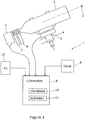
- a first embodiment of the invention shows a navigational system 1 comprising a telescope 2 mounted on an equatorial mount 3.
- the mount is able to measure and store the position in which the telescope 2 is pointing at any given time.
- a CCD sensor 4 Within the focal plane of the telescope is mounted a CCD sensor 4, that is arranged to receive and detect light travelling down the telescope from distant objects such as a star 5.
- a pair of filter wheels 6, 7, allow for a diffraction grating and one or more filters, such as pass-band filters, to be positioned in the path of incoming light before it is incident on the sensor 4.
- Filter wheel 6 allows the inclusion of a Red (R) filter and/or Infrared (I) filter, that may be used for daylight observations as atmospheric transmission is slightly better towards longer wavelengths, e.g. towards the R and I pass-bands of the Johnson-Cousins UBVRI system.
- Filter 7 allows the inclusion of a diffraction grating that splits the light into its component wavelengths before the light is captured by the CCD 4. Use of the diffraction grating therefore allows a relatively straightforward analysis of the spectrum of the star 5 (or other celestial body) to take place.
- a slit may use a slit to mask some of the background noise and enable better sky subtraction, particularly for daytime or twilight use.
- An embodiment that uses a slit has the slit located at a focal plane of the optical device. The slit may also augment the diffraction process.
- the CCD provides a digital output signal to a computer 8, comprising a processor and storage.
- a computer 8 comprising a processor and storage.
- a database 10 of the spectra of some of brightest objects in the night sky, (including the 58 special status navigational stars).
- a reference clock 9 that determines the time from a radio time code signal such as the German DCF77 or the British MSF signal, or from a similar time signal, is also connected to the computer, and is able to supply the time to the computer on demand.
- a device 12 for measuring the azimuth at which the telescope is pointing which may comprise a compass or inertial navigation system, also provides an input to the computer 8.
- the diffraction acts to split the incoming light into its various spectral components, and to present this spectrum on the CCD.
- the computer 8 is arranged to accept image information from the CCD, and to process it using image processing software in a known manner to obtain the spectrum from which it is possible to obtain relative flux data over a range of wavelengths.
- it obtains a time reference from the clock 9, and positional information from the mount 3, comprising information indicating the direction in which the telescope is pointing. It then compares the spectrum to the database, to find a best match, using pattern matching software. In making the comparison, it limits its search based upon any a priori knowledge of the geographical position of the telescope, effectively creating a subset of the reference data.
- the embodiment may customise the limit based upon the expected accuracy of the a priori knowledge.
- a basic limit is to limit the database comparison to those celestial objects that lie within 90° of the expected position at the time the observation was made. Finer limits, that reduce this angle, may be imposed if greater confidence in the current geographical position, and also in the telescope pointing direction is had.
- the pattern matching performed by the computer 8 is based upon comparison of spectral signatures of one or more observed stars against a database of previously acquired measurements.
- the spectral signature is obtained from observed spectra by applying filtering to remove both low and high spatial frequency information (reducing the influence of sensor noise, sensor spectral response and variation in sensor black point), followed by normalisation and, optionally (but is done in this example), computing the gradient of spectrum to give increased emphasis to distinct spectral features.
- the pattern matching takes account of both the typical spectral response and variations thereof.
- the variation information is used when comparing spectra so that the most informative wavelengths have more influence when making comparisons.
- Filters used to extract spectral signatures for pattern matching may be optimised given a set of reference observations, e.g. to maximise the likelihood of correctly identifying the correct star.
- the filters (and parameters thereof) may advantageously be changed dynamically for different known operating scenarios (e.g. searching for particular stars or operation in different ambient light levels).
- the output as a result of a pattern match in the database will be, given a suitably clear observation of an object that sits within the database 10, a positive identification of the object.
- the computer therefore now has positional information from the mount, along with time information at which a known celestial body was at the recorded position, this information comprising basic navigational information.
- the computer has commonly available almanac software 11 within its storage that, given the basic navigational information, provides a navigational position, or fix, on the Earth at which the telescope was located at the observation time. The accuracy of the fix is dependent upon the accuracy of the basic navigational information collected, as with previous methods of celestial navigation.
- Figure 2 shows 2D Cartesian plots of spectra obtained using a system as described in relation to Figure 1 .
- the spectra were obtained at night.
- Figure 2a shows the spectrum of Aldebaran, the 16 th brightest star, which is found in the constellation of Taurus.
- Figure 2b shows the spectrum of Betelgeuse, the 9 th brightest star, located in Orion.
- the vertical scale is in arbitrary units of relative flux. Note the different horizontal axes. Clear differences between the spectra can be seen - not only in the horizontal position of the bulk of the energy, but also in the detail of the peaks. This is caused by the differing physical characteristics of the stars e.g. chemical composition and temperature making up the outer layers of the stars. The differing characteristics create different absorption bands within the spectra.
- the spectra were measured with a relatively low cost diffraction grating.
- Other embodiments may use an improved diffraction grating, that provides a greater resolution of the spectrum, so providing more distinguishing features of each star, and hence making identification simpler.
- Other embodiments may also use a slit, e.g. as described above, to reduce noise and enable better sky subtraction.
- spectra shown enable image processing and/or pattern matching software running on a processor in an embodiment of the invention to distinguish between the two spectra, when comparing a measured spectrum with one in its referenced database.
- the spectra of many other stars also have unique features that enable them to be distinguished by the pattern matching software.
- Figure 3 shows 2D Cartesian plots of spectra from three different stars, along with the plot obtained from processing each spectrum according to the methods described herein.
- Figure 3a (i) the spectra of the star Sheat is shown. It will be seen that this plot of its spectrum exhibits distinctive characteristics due to absorption lines.
- the processed spectrum is shown at Figure 3a(ii) . The processing carried out was:
- Figures, 3b and 3c sh ow spectra (at (i)), and the results of the processing above (at (ii)) for the stars Shedar and Pollux respectively. It will be noticed that the spectra of Figures 3b(i) and 3c(i) are very similar, and it would be very difficult to distinguish these by eye. However, when the spectra are processed as described above, differences start to emerge. See for example the waveform corresponding to the horizontal axis at the point marked x. The amplitudes at that point differ more significantly, making the subsequent pattern matching process more likely to identify the correct star.
- Figure 4 shows how a single, known celestial object can be used to provide a navigational fix, that, given also azimuthal information, such as a compass bearing of the direction of the celestial object (and the time of measurement, as is usually done), can provide a unique position, within the bounds of measurement error.
- a part of the Earth 30 is shown, along with a celestial object, such as a star 31.
- An observer on the Earth located at point A will observe the star 31 at an elevation angle ⁇ , and at a compass bearing of due south.
- This elevation angle coupled with the time of observation, can provide a navigational fix that is some (as yet unknown) point on the circle 32, using a standard nautical almanac.
- the star will appear at the same elevation angle ⁇ at every point on the circle 32 and hence an elevation angle alone will be insufficient to derive a position, other than the knowledge that the observer is somewhere on the circle.
- an observer at point B will see the star 31 at a similar elevation angle ⁇ , but with a compass bearing of due north.
- an observer at C will see the star at the same elevation angle, but with a compass bearing broadly north east.
- Azimuthal information such as derived from an inertial navigation system, or compass bearing can be used to locate the observer on the circle, and so provide a unique fix.
- the current invention provides the means for identifying many of the stars, without reference to any other star (e.g. using a more traditional star pattern for identification purposes), and so therefore allows the technique described in relation to Figure 4 to provide the navigational fix should just one of the stars be visible.
- FIG. 5a shows a further embodiment of the invention.
- a system 40 comprises a telescope 42 mounted on an altazimuth motorised mount 44.
- the telescope has a CCD sensor 46, and a diffraction grating 48 for producing a spectral output on the CCD of light entering the telescope, and a filter 49 for daylight observations, whereby shorter wavelengths such as blue light are excluded from entering the diffraction grating.
- this filter may be varied according to e.g. the time of day in which observations are being made, or local the atmospheric conditions, so as to reduce undesirable wavelengths from being processed.
- An All-sky camera 50 (such as an Occulus All-Sky Camera available from www.sxccd.com) is arranged to have a wide-angle view of the whole sky, or a significant portion thereof.
- the telescope CCD 46, the mount 48, and the All-sky camera 50 are all connected to a control unit 52, which may comprise of a general purpose computer, or a specialised computer arranged to process the information from its inputs, and to control the mount so as to direct the telescope 42 to point to a desired region of the sky.
- the positions of the telescope and the All-sky camera are calibrated, such that the control unit is able to direct the telescope mount to point the telescope to a given point, as determined from an image provided by the All-sky camera.
- the All-sky-camera 50 provides sky images to the control unit 52.
- the control unit examines the images, and identifies one or more bright point, which may be celestial objects pertinent to navigation. A chosen point is selected, and the position in the sky determined, from the positional calibration carried out earlier.
- the control unit then directs the telescope to point to the chosen object with appropriate signals being sent to the mount 44, and when it has done so, the image from the CCD sensor is captured.
- This image comprises of a spectral response, which when extracted and plotted in 2D Cartesian format is as shown in Figure 5b .
- the spectral data is then processed and analysed, again as described previously, by comparing it to similarly processed reference data of celestial objects stored in the control unit. A match above a given threshold provides an identification of the object, and its positional information, as determined by the telescope is used as previously described to produce a full or partial navigational fix.
- the sky camera may be arranged to supply images to the controller at intervals, such as every few seconds, and the telescope directed to the next point to produce a spectrum, and an identification of the point attempted as before.
- Figure 5c shows an image 54 as may be provided by the sky camera 50 to the controller 52.
- the controller has, in this case already directed the telescope 42 to point to object 56, and the spectrum from that image has been processed. This image however also reveals (due e.g. to movements in clouds 56 etc.) a new bright object 58.
- the controller may then instruct the telescope mount to slew the telescope to point to the newly revealed object 58, to obtain a new spectrum therefrom.
- the system can continuously seek and attempt to identify objects, to produce navigational information which may be combined with previously obtained data to improve the accuracy of the navigational fix.
- the system may be arranged, when activated, to work in the manner described above to generate a navigational fix that may be interrogated as desired by other systems.
- the navigational fix may be provided, along with an estimate of its accuracy, based upon factors such as the number of stars used in generating the fix, the positional accuracy of the azimuth and elevation data, and the timing accuracy of the measurements obtained.
- the invention may be used on its own, to provide a navigational fix, or may be used in conjunction with other navigational systems, to provide an alternative, or a backup solution.
- the results from embodiments of the invention may advantageously be fused or otherwise combined with the results from the other systems.
- the celestial object may be a star, or may be a planet, although it is likely that it will predominantly be used with stars.
Landscapes
- Physics & Mathematics (AREA)
- Engineering & Computer Science (AREA)
- Radar, Positioning & Navigation (AREA)
- Remote Sensing (AREA)
- General Physics & Mathematics (AREA)
- Spectroscopy & Molecular Physics (AREA)
- Astronomy & Astrophysics (AREA)
- Automation & Control Theory (AREA)
- Electromagnetism (AREA)
- Spectrometry And Color Measurement (AREA)
- Navigation (AREA)
Claims (16)
- Verfahren zum Berechnen einer geographischen Position auf der Erdoberfläche anhand mindestens eines Himmelsobjekts, umfassend die folgenden Schritte:a) Richten einer optischen Vorrichtung auf ein Himmelsobjekt, um elektromagnetische Strahlung davon zu empfangen;b) Beugen oder Brechen der elektromagnetischen Strahlung, um ein Spektrum des Himmelsobjekts zu erhalten;c) Messen der Intensität oder des relativen Stroms des Spektrums mit einer Auflösung, die hoch genug ist, um Absorptions- und/oder Emissionsliniendaten über einen breiten Bereich von Wellenlängen zu erfassen;d) Identifizieren des Himmelsobjekts durch Vergleichen über Musterabgleich der Absorptions- und/oder Emissionsliniendaten aus Schritt (c) mit in einer Referenzdatenbank von Himmelsobjekten enthaltenen Spektren;e) Messen des Elevations- und Azimutwinkels des Objekts zusammen mit der Zeit, zu der das Spektrum beobachtet wurde;f) Verwenden der in den Schritten d) und e) erhaltenen Informationen zusammen mit einer vorkompilierten Tabelle von Himmelskörperpositionen, um eine geographische Position der optischen Vorrichtung zu berechnen.
- Verfahren nach Anspruch 1, wobei die Beugung des Lichts, um ein Spektrum davon zu erhalten, unter Verwendung eines Diffraktionsgitters und eines optischen Multipixelsensors, wie etwa eines digitalen Kamerasensors, durchgeführt wird.
- Verfahren nach Anspruch 1 oder Anspruch 2, wobei das erhaltene Spektrum untersucht wird, um strukturelle Elemente zu identifizieren, die mindestens seine Absorptions- und/oder Emissionslinien beinhalten.
- Verfahren nach Anspruch 3, wobei das Spektrum verarbeitet wird, bevor es mit Referenzdaten verglichen wird, wobei die Verarbeitung die folgenden Schritte umfasst:a) räumliches Filtern des Spektrums, um sehr feine räumliche Details, die Sensorrauschen entsprechen, und sehr grobe räumliche Details, die Auswirkungen einer groben Empfindlichkeitsreaktionskurve des Sensors und Variationen des Schwarzpunkts über den Sensor entsprechen, zu entfernen;b) Normalisieren des gefilterten Spektrums, um eine erhöhte Konsistenz über verschiedene Beobachtungen bereitzustellen.
- Verfahren nach Anspruch 4, wobei die vorherige Bearbeitung ferner den Schritt des Erzeugens eines Gradientensignals, das die Änderung der Intensität mit der Wellenlänge des Spektrums betrifft, und des Durchführens einer anschließenden Verarbeitung unter Verwendung des Spektrumgradientensignals umfasst.
- Verfahren nach einem der vorangehenden Ansprüche, wobei der Schritt des Identifizierens des Himmelsobjekts durch Kreuzkorrelieren des Spektrums, wenn das Verfahren von Anspruch 1 bis 3 abhängig ist, oder des verarbeiteten Spektrums, wenn das Verfahren von Anspruch 4 abhängig ist, mit Referenzspektren, die zuvor von bekannten Himmelsobjekten erfasst wurden, und Auswählen des Referenzspektrums, das eine Korrelation über einem vorbestimmten Schwellenwert aufweist, erfolgt.
- Verfahren nach einem der vorangehenden Ansprüche, wobei die Referenzdatenbank für jeden Himmelskörper eine Vielzahl von Messungen davon umfasst, die in unterschiedlichen Umweltbedingungen ermittelt wurden, um statistische Informationen zur Verwendung in dem Musterabstimmungsvorgang bereitzustellen.
- Verfahren nach Anspruch 7, wobei die Musterabstimmung Abstimmen des verarbeiteten Spektrums mit statistischen Darstellungen der in der Referenzdatenbank gespeicherten bekannten Himmelsobjekte umfasst, um eine maximale Beobachtungswahrscheinlichkeit zu ermitteln.
- Verfahren nach einem der vorangehenden Ansprüche, wobei mindestens eines von: der Leuchtkraft und einem vorausgewählten Farbindex des Himmelsobjekts außerdem als Unterscheidungskriterium bei der Identifizierung des Himmelsobjekts verwendet wird.
- Verfahren nach einem der vorangehenden Ansprüche, wobei die Referenzdatenbank aus Himmelsobjekten besteht, die messbar unterschiedliche spektrale Merkmale als andere derartige Himmelsobjekte in ihrer Nachbarschaft aufweisen, wobei die Referenzdatenbank Objekte beinhaltet, die mindestens aus den 20, 30, 40, 50, 58, 70, 100 oder 130 hellsten Himmelsobjekten ausgewählt sind.
- Verfahren nach einem der vorangehenden Ansprüche, wobei das in Schritt b) erhaltene Spektrum gefiltert oder korrigiert wird, um die Auswirkungen von Strahlung, die nicht von dem Himmelsobjekt ausgegangen ist, zu entfernen, zu verringern oder anderweitig auszugleichen.
- Verfahren nach Anspruch 11, wobei das Filtern oder die Korrektur eine Spektrumkalibriermessung verwendet, die von einem Bereich erfasst wurde, in dem Licht auf terrestrische Quellen oder die chemische Zusammensetzung der Erdatmosphäre zurückzuführen ist und/oder von der Sonne ausgeht.
- Verfahren nach einem der vorangehenden Ansprüche, wobei die optische Vorrichtung eine Kameralinse oder ein Teleskop ist.
- Himmelsnavigationssystem zum Berechnen einer geographischen Position auf der Erdoberfläche, umfassend:eine optische Vorrichtung zum Empfangen von Licht von einem Himmelsobjekt; ein Mittel zum Messen einer Ausrichtung der optischen Vorrichtung;ein Spektrometer zum Messen spektraler Eigenschaften von Licht an einem Ausgang der optischen Vorrichtung;eine Uhr zum Messen der Zeit; undeinen Prozessor zum Aufzeichnen von Eingaben von der Uhr, dem Spektrometer und den Mitteln zum Messen der Ausrichtung der optischen Vorrichtung;wobei der Prozessor dazu ausgelegt ist, ein durch das Spektrometer erzeugtes Spektrum eines von der optischen Vorrichtung beobachteten Objekts durch Musterabstimmung mit Referenzspektren von Himmelsobjekten in einer Referenzdatenbank zu vergleichen, und beim Finden einer Übereinstimmung, unter Verwendung einer vorkompilierten Tabelle von Himmelskörperpositionen zusammen mit einer aufgezeichneten Beobachtungszeit und Informationen in Bezug auf die Ausrichtung der optischen Vorrichtung, einschließlich Elevations- und Azimutwinkel, zu dem Zeitpunkt der Beobachtung, eine geographische Position der optischen Vorrichtung als eine Navigationspositionsbestimmung für die optische Vorrichtung zu berechnen.
- Himmelsnavigationssystem nach Anspruch 14, wobei das Spektrometer ein Diffraktionsgitter und ein lichtempfindliches Element umfasst.
- Himmelsnavigationssystem nach Anspruch 14 oder 15, wobei der Prozessor dazu ausgelegt ist, die Auswirkungen von Strahlung, die nicht von dem Himmelsobjekt ausgegangen ist, zu entfernen, zu verringern oder anderweitig auszugleichen.
Applications Claiming Priority (2)
| Application Number | Priority Date | Filing Date | Title |
|---|---|---|---|
| GBGB1604556.9A GB201604556D0 (en) | 2016-03-17 | 2016-03-17 | Celestial navigation system |
| PCT/EP2017/056169 WO2017158055A1 (en) | 2016-03-17 | 2017-03-15 | Celestial navigation system |
Publications (2)
| Publication Number | Publication Date |
|---|---|
| EP3430353A1 EP3430353A1 (de) | 2019-01-23 |
| EP3430353B1 true EP3430353B1 (de) | 2020-01-22 |
Family
ID=55968481
Family Applications (1)
| Application Number | Title | Priority Date | Filing Date |
|---|---|---|---|
| EP17710933.7A Active EP3430353B1 (de) | 2016-03-17 | 2017-03-15 | Himmelnavigationssystem |
Country Status (5)
| Country | Link |
|---|---|
| US (1) | US11209273B2 (de) |
| EP (1) | EP3430353B1 (de) |
| ES (1) | ES2774494T3 (de) |
| GB (1) | GB201604556D0 (de) |
| WO (1) | WO2017158055A1 (de) |
Families Citing this family (8)
| Publication number | Priority date | Publication date | Assignee | Title |
|---|---|---|---|---|
| US20190353484A1 (en) * | 2018-02-22 | 2019-11-21 | Government Of The United States Of America, As Represented By The Secretary Of The Navy | Methods and apparatuses for determining attitude information from stars using color information |
| US11371846B2 (en) | 2019-01-14 | 2022-06-28 | Qatar Foundation For Education Science And Community Development | Systems and methods for determining the position of a device |
| CN110763240B (zh) * | 2019-11-22 | 2021-07-30 | 北京理工大学 | 融合轨道机动数据的小天体接近高精度光学导航方法 |
| DE102020104911A1 (de) | 2020-02-25 | 2021-08-26 | Rolls-Royce Deutschland Ltd & Co Kg | Navigationssystem und -verfahren |
| CN111578934B (zh) * | 2020-04-30 | 2022-07-29 | 中国人民解放军国防科技大学 | 基于惯性/天文组合导航应用的折射星优选方法及系统 |
| CN111766696B (zh) * | 2020-06-12 | 2021-09-17 | 中国科学院长春光学精密机械与物理研究所 | 一种地平式光电望远镜图像旋转的消除方法及装置 |
| CN113945210B (zh) * | 2021-10-15 | 2024-06-18 | 中国科学院长春光学精密机械与物理研究所 | 地基大口径光学望远镜的快速定位方法、装置及望远镜 |
| CN114862723B (zh) * | 2022-05-31 | 2024-03-01 | 中国科学院上海天文台 | 一种基于测量密集星场的天文望远镜像场畸变标定方法 |
Family Cites Families (22)
| Publication number | Priority date | Publication date | Assignee | Title |
|---|---|---|---|---|
| US3100264A (en) * | 1960-01-28 | 1963-08-06 | Polarad Electronics Corp | Star energy identification system for space navigation |
| US3393320A (en) * | 1964-08-07 | 1968-07-16 | Itek Corp | Data pattern motion cancellation system using image amplifier with electrical deflection of the electron stream |
| US3769710A (en) * | 1969-04-01 | 1973-11-06 | R Reister | Electronic celestial navigation means |
| US4621329A (en) | 1979-12-31 | 1986-11-04 | Itek Corporation | Star catalog navigation system |
| US6008492A (en) * | 1996-10-23 | 1999-12-28 | Slater; Mark | Hyperspectral imaging method and apparatus |
| US6049622A (en) * | 1996-12-05 | 2000-04-11 | Mayo Foundation For Medical Education And Research | Graphic navigational guides for accurate image orientation and navigation |
| US7542849B2 (en) * | 2005-06-03 | 2009-06-02 | Terahop Networks, Inc. | Network aided terrestrial triangulation using stars (NATTS) |
| CA2547359C (en) * | 2003-11-26 | 2012-11-27 | Florida Environmental Research Institute, Inc. | Spectral imaging system |
| US7197381B2 (en) * | 2003-12-08 | 2007-03-27 | University Of Maryland | Navigational system and method utilizing sources of pulsed celestial radiation |
| US7349803B2 (en) * | 2004-10-18 | 2008-03-25 | Trex Enterprises Corp. | Daytime stellar imager |
| US7447591B2 (en) * | 2004-10-18 | 2008-11-04 | Trex Enterprises Corp. | Daytime stellar imager for attitude determination |
| US8072581B1 (en) * | 2007-01-19 | 2011-12-06 | Rockwell Collins, Inc. | Laser range finding system using variable field of illumination flash lidar |
| US7925167B1 (en) * | 2007-10-31 | 2011-04-12 | Kozubal Marek J | Satellite downlink via patterns of uncollimated light |
| US8222582B1 (en) | 2008-09-30 | 2012-07-17 | Anderson Mark J | Celestial navigation using stellar narrow-band emission |
| US8355868B2 (en) | 2009-09-30 | 2013-01-15 | Ge Aviation Systems Llc | Method and system for spectral image celestial navigation |
| US8694051B2 (en) | 2010-05-07 | 2014-04-08 | Qualcomm Incorporated | Orientation sensor calibration |
| US8620582B2 (en) * | 2011-01-04 | 2013-12-31 | Blackberry Limited | Device position method and apparatus using celestial objects |
| US9341517B1 (en) * | 2013-03-15 | 2016-05-17 | Wavefront Research, Inc. | Optical angular measurement sensors |
| CN104457760B (zh) | 2014-11-05 | 2017-08-29 | 上海卫星工程研究所 | 高分辨率光栅型光谱导航仪设计系统及其设计方法 |
| US9702702B1 (en) * | 2015-06-15 | 2017-07-11 | The Charles Stark Draper Laboratory, Inc. | Methods and apparatus for navigational aiding using celestial object tracking |
| US11150357B2 (en) * | 2017-04-24 | 2021-10-19 | The Charles Stark Draper Laboratory, Inc. | Multi-source distributed navigation system architecture |
| US10605603B2 (en) * | 2017-09-11 | 2020-03-31 | Goodrich Corporation | Navigation systems and methods |
-
2016
- 2016-03-17 GB GBGB1604556.9A patent/GB201604556D0/en not_active Ceased
-
2017
- 2017-03-15 EP EP17710933.7A patent/EP3430353B1/de active Active
- 2017-03-15 US US16/081,655 patent/US11209273B2/en active Active
- 2017-03-15 ES ES17710933T patent/ES2774494T3/es active Active
- 2017-03-15 WO PCT/EP2017/056169 patent/WO2017158055A1/en not_active Ceased
Non-Patent Citations (1)
| Title |
|---|
| None * |
Also Published As
| Publication number | Publication date |
|---|---|
| EP3430353A1 (de) | 2019-01-23 |
| WO2017158055A1 (en) | 2017-09-21 |
| ES2774494T3 (es) | 2020-07-21 |
| US20190086209A1 (en) | 2019-03-21 |
| GB201604556D0 (en) | 2016-05-04 |
| US11209273B2 (en) | 2021-12-28 |
Similar Documents
| Publication | Publication Date | Title |
|---|---|---|
| US11209273B2 (en) | Celestial navigation system | |
| US7447591B2 (en) | Daytime stellar imager for attitude determination | |
| US7349804B2 (en) | Daytime stellar imager | |
| US7349803B2 (en) | Daytime stellar imager | |
| US7541975B2 (en) | Enhanced GNSS signal processing | |
| Eismann et al. | Automated hyperspectral cueing for civilian search and rescue | |
| Healey et al. | Models and methods for automated material identification in hyperspectral imagery acquired under unknown illumination and atmospheric conditions | |
| US20110004405A1 (en) | Earth horizon sensor | |
| US20180082438A1 (en) | Method of determining a direction of an object on the basis of an image of the object | |
| CN104502918A (zh) | 一种低轨卫星星载图谱关联探测方法与载荷 | |
| Fernandez-Moran et al. | Towards a novel approach for Sentinel-3 synergistic OLCI/SLSTR cloud and cloud shadow detection based on stereo cloud-top height estimation | |
| Ehrlich et al. | Airborne hyperspectral observations of surface and cloud directional reflectivity using a commercial digital camera | |
| Seiz et al. | Cloud mapping with ground‐based photogrammetric cameras | |
| Amin et al. | Optical algorithm for cloud shadow detection over water | |
| RU2535247C1 (ru) | Способ и устройство измерения угловых координат звезд | |
| Quick et al. | Airborne radiometric validation of the geostationary lightning mapper using the Fly’s Eye GLM Simulator | |
| Van de Steene et al. | Near-infrared and Br_gamma observations of post-AGB stars | |
| Roshanian et al. | 2MASS infrared star catalog data mining for use onboard a daytime star tracker | |
| EP2972452B1 (de) | System zur lichtquellenortserkennung | |
| Gudmundson | Ground based attitude determination using a SWIR star tracker | |
| Wulder et al. | Mission planning for operational data acquisition campaigns with the CASI | |
| Stickel et al. | The optical cut-off source 0500+ 019: A background quasar seen through a foreground galaxy? | |
| FR2979022A1 (fr) | Dispositif de visee a chercheur de nord stellaire et procede de recalage d'un compas magnetique d'un tel dispositif | |
| Ressler et al. | Two protostar candidates in the bright-rimmed dark cloud LDN 1206 | |
| Skuljan | Astrometric and photometric measurements of GEO satellites in proximity operations over the Pacific |
Legal Events
| Date | Code | Title | Description |
|---|---|---|---|
| STAA | Information on the status of an ep patent application or granted ep patent |
Free format text: STATUS: UNKNOWN |
|
| STAA | Information on the status of an ep patent application or granted ep patent |
Free format text: STATUS: THE INTERNATIONAL PUBLICATION HAS BEEN MADE |
|
| PUAI | Public reference made under article 153(3) epc to a published international application that has entered the european phase |
Free format text: ORIGINAL CODE: 0009012 |
|
| STAA | Information on the status of an ep patent application or granted ep patent |
Free format text: STATUS: REQUEST FOR EXAMINATION WAS MADE |
|
| 17P | Request for examination filed |
Effective date: 20180918 |
|
| AK | Designated contracting states |
Kind code of ref document: A1 Designated state(s): AL AT BE BG CH CY CZ DE DK EE ES FI FR GB GR HR HU IE IS IT LI LT LU LV MC MK MT NL NO PL PT RO RS SE SI SK SM TR |
|
| AX | Request for extension of the european patent |
Extension state: BA ME |
|
| DAV | Request for validation of the european patent (deleted) | ||
| DAX | Request for extension of the european patent (deleted) | ||
| GRAP | Despatch of communication of intention to grant a patent |
Free format text: ORIGINAL CODE: EPIDOSNIGR1 |
|
| STAA | Information on the status of an ep patent application or granted ep patent |
Free format text: STATUS: GRANT OF PATENT IS INTENDED |
|
| INTG | Intention to grant announced |
Effective date: 20191010 |
|
| RIN1 | Information on inventor provided before grant (corrected) |
Inventor name: FOULKES, STEPHEN BARRY Inventor name: KENT, PHILIP JOHN Inventor name: O'DELL, MARK, ANTHONY |
|
| GRAS | Grant fee paid |
Free format text: ORIGINAL CODE: EPIDOSNIGR3 |
|
| GRAA | (expected) grant |
Free format text: ORIGINAL CODE: 0009210 |
|
| STAA | Information on the status of an ep patent application or granted ep patent |
Free format text: STATUS: THE PATENT HAS BEEN GRANTED |
|
| AK | Designated contracting states |
Kind code of ref document: B1 Designated state(s): AL AT BE BG CH CY CZ DE DK EE ES FI FR GB GR HR HU IE IS IT LI LT LU LV MC MK MT NL NO PL PT RO RS SE SI SK SM TR |
|
| REG | Reference to a national code |
Ref country code: GB Ref legal event code: FG4D |
|
| REG | Reference to a national code |
Ref country code: CH Ref legal event code: EP |
|
| REG | Reference to a national code |
Ref country code: AT Ref legal event code: REF Ref document number: 1227190 Country of ref document: AT Kind code of ref document: T Effective date: 20200215 |
|
| REG | Reference to a national code |
Ref country code: IE Ref legal event code: FG4D |
|
| REG | Reference to a national code |
Ref country code: DE Ref legal event code: R096 Ref document number: 602017010936 Country of ref document: DE |
|
| REG | Reference to a national code |
Ref country code: NL Ref legal event code: MP Effective date: 20200122 |
|
| REG | Reference to a national code |
Ref country code: ES Ref legal event code: FG2A Ref document number: 2774494 Country of ref document: ES Kind code of ref document: T3 Effective date: 20200721 |
|
| REG | Reference to a national code |
Ref country code: LT Ref legal event code: MG4D |
|
| PG25 | Lapsed in a contracting state [announced via postgrant information from national office to epo] |
Ref country code: NL Free format text: LAPSE BECAUSE OF FAILURE TO SUBMIT A TRANSLATION OF THE DESCRIPTION OR TO PAY THE FEE WITHIN THE PRESCRIBED TIME-LIMIT Effective date: 20200122 Ref country code: RS Free format text: LAPSE BECAUSE OF FAILURE TO SUBMIT A TRANSLATION OF THE DESCRIPTION OR TO PAY THE FEE WITHIN THE PRESCRIBED TIME-LIMIT Effective date: 20200122 Ref country code: PT Free format text: LAPSE BECAUSE OF FAILURE TO SUBMIT A TRANSLATION OF THE DESCRIPTION OR TO PAY THE FEE WITHIN THE PRESCRIBED TIME-LIMIT Effective date: 20200614 Ref country code: NO Free format text: LAPSE BECAUSE OF FAILURE TO SUBMIT A TRANSLATION OF THE DESCRIPTION OR TO PAY THE FEE WITHIN THE PRESCRIBED TIME-LIMIT Effective date: 20200422 Ref country code: FI Free format text: LAPSE BECAUSE OF FAILURE TO SUBMIT A TRANSLATION OF THE DESCRIPTION OR TO PAY THE FEE WITHIN THE PRESCRIBED TIME-LIMIT Effective date: 20200122 |
|
| PG25 | Lapsed in a contracting state [announced via postgrant information from national office to epo] |
Ref country code: BG Free format text: LAPSE BECAUSE OF FAILURE TO SUBMIT A TRANSLATION OF THE DESCRIPTION OR TO PAY THE FEE WITHIN THE PRESCRIBED TIME-LIMIT Effective date: 20200422 Ref country code: IS Free format text: LAPSE BECAUSE OF FAILURE TO SUBMIT A TRANSLATION OF THE DESCRIPTION OR TO PAY THE FEE WITHIN THE PRESCRIBED TIME-LIMIT Effective date: 20200522 Ref country code: LV Free format text: LAPSE BECAUSE OF FAILURE TO SUBMIT A TRANSLATION OF THE DESCRIPTION OR TO PAY THE FEE WITHIN THE PRESCRIBED TIME-LIMIT Effective date: 20200122 Ref country code: SE Free format text: LAPSE BECAUSE OF FAILURE TO SUBMIT A TRANSLATION OF THE DESCRIPTION OR TO PAY THE FEE WITHIN THE PRESCRIBED TIME-LIMIT Effective date: 20200122 Ref country code: HR Free format text: LAPSE BECAUSE OF FAILURE TO SUBMIT A TRANSLATION OF THE DESCRIPTION OR TO PAY THE FEE WITHIN THE PRESCRIBED TIME-LIMIT Effective date: 20200122 Ref country code: GR Free format text: LAPSE BECAUSE OF FAILURE TO SUBMIT A TRANSLATION OF THE DESCRIPTION OR TO PAY THE FEE WITHIN THE PRESCRIBED TIME-LIMIT Effective date: 20200423 |
|
| REG | Reference to a national code |
Ref country code: DE Ref legal event code: R097 Ref document number: 602017010936 Country of ref document: DE |
|
| PG25 | Lapsed in a contracting state [announced via postgrant information from national office to epo] |
Ref country code: SM Free format text: LAPSE BECAUSE OF FAILURE TO SUBMIT A TRANSLATION OF THE DESCRIPTION OR TO PAY THE FEE WITHIN THE PRESCRIBED TIME-LIMIT Effective date: 20200122 Ref country code: EE Free format text: LAPSE BECAUSE OF FAILURE TO SUBMIT A TRANSLATION OF THE DESCRIPTION OR TO PAY THE FEE WITHIN THE PRESCRIBED TIME-LIMIT Effective date: 20200122 Ref country code: SK Free format text: LAPSE BECAUSE OF FAILURE TO SUBMIT A TRANSLATION OF THE DESCRIPTION OR TO PAY THE FEE WITHIN THE PRESCRIBED TIME-LIMIT Effective date: 20200122 Ref country code: DK Free format text: LAPSE BECAUSE OF FAILURE TO SUBMIT A TRANSLATION OF THE DESCRIPTION OR TO PAY THE FEE WITHIN THE PRESCRIBED TIME-LIMIT Effective date: 20200122 Ref country code: MC Free format text: LAPSE BECAUSE OF FAILURE TO SUBMIT A TRANSLATION OF THE DESCRIPTION OR TO PAY THE FEE WITHIN THE PRESCRIBED TIME-LIMIT Effective date: 20200122 Ref country code: RO Free format text: LAPSE BECAUSE OF FAILURE TO SUBMIT A TRANSLATION OF THE DESCRIPTION OR TO PAY THE FEE WITHIN THE PRESCRIBED TIME-LIMIT Effective date: 20200122 Ref country code: CZ Free format text: LAPSE BECAUSE OF FAILURE TO SUBMIT A TRANSLATION OF THE DESCRIPTION OR TO PAY THE FEE WITHIN THE PRESCRIBED TIME-LIMIT Effective date: 20200122 Ref country code: LT Free format text: LAPSE BECAUSE OF FAILURE TO SUBMIT A TRANSLATION OF THE DESCRIPTION OR TO PAY THE FEE WITHIN THE PRESCRIBED TIME-LIMIT Effective date: 20200122 |
|
| REG | Reference to a national code |
Ref country code: CH Ref legal event code: PL |
|
| REG | Reference to a national code |
Ref country code: AT Ref legal event code: MK05 Ref document number: 1227190 Country of ref document: AT Kind code of ref document: T Effective date: 20200122 |
|
| PLBE | No opposition filed within time limit |
Free format text: ORIGINAL CODE: 0009261 |
|
| STAA | Information on the status of an ep patent application or granted ep patent |
Free format text: STATUS: NO OPPOSITION FILED WITHIN TIME LIMIT |
|
| REG | Reference to a national code |
Ref country code: BE Ref legal event code: MM Effective date: 20200331 |
|
| 26N | No opposition filed |
Effective date: 20201023 |
|
| PG25 | Lapsed in a contracting state [announced via postgrant information from national office to epo] |
Ref country code: LU Free format text: LAPSE BECAUSE OF NON-PAYMENT OF DUE FEES Effective date: 20200315 |
|
| PG25 | Lapsed in a contracting state [announced via postgrant information from national office to epo] |
Ref country code: IE Free format text: LAPSE BECAUSE OF NON-PAYMENT OF DUE FEES Effective date: 20200315 Ref country code: CH Free format text: LAPSE BECAUSE OF NON-PAYMENT OF DUE FEES Effective date: 20200331 Ref country code: AT Free format text: LAPSE BECAUSE OF FAILURE TO SUBMIT A TRANSLATION OF THE DESCRIPTION OR TO PAY THE FEE WITHIN THE PRESCRIBED TIME-LIMIT Effective date: 20200122 Ref country code: LI Free format text: LAPSE BECAUSE OF NON-PAYMENT OF DUE FEES Effective date: 20200331 |
|
| PG25 | Lapsed in a contracting state [announced via postgrant information from national office to epo] |
Ref country code: SI Free format text: LAPSE BECAUSE OF FAILURE TO SUBMIT A TRANSLATION OF THE DESCRIPTION OR TO PAY THE FEE WITHIN THE PRESCRIBED TIME-LIMIT Effective date: 20200122 Ref country code: BE Free format text: LAPSE BECAUSE OF NON-PAYMENT OF DUE FEES Effective date: 20200331 Ref country code: PL Free format text: LAPSE BECAUSE OF FAILURE TO SUBMIT A TRANSLATION OF THE DESCRIPTION OR TO PAY THE FEE WITHIN THE PRESCRIBED TIME-LIMIT Effective date: 20200122 |
|
| PG25 | Lapsed in a contracting state [announced via postgrant information from national office to epo] |
Ref country code: TR Free format text: LAPSE BECAUSE OF FAILURE TO SUBMIT A TRANSLATION OF THE DESCRIPTION OR TO PAY THE FEE WITHIN THE PRESCRIBED TIME-LIMIT Effective date: 20200122 Ref country code: MT Free format text: LAPSE BECAUSE OF FAILURE TO SUBMIT A TRANSLATION OF THE DESCRIPTION OR TO PAY THE FEE WITHIN THE PRESCRIBED TIME-LIMIT Effective date: 20200122 Ref country code: CY Free format text: LAPSE BECAUSE OF FAILURE TO SUBMIT A TRANSLATION OF THE DESCRIPTION OR TO PAY THE FEE WITHIN THE PRESCRIBED TIME-LIMIT Effective date: 20200122 |
|
| PG25 | Lapsed in a contracting state [announced via postgrant information from national office to epo] |
Ref country code: MK Free format text: LAPSE BECAUSE OF FAILURE TO SUBMIT A TRANSLATION OF THE DESCRIPTION OR TO PAY THE FEE WITHIN THE PRESCRIBED TIME-LIMIT Effective date: 20200122 Ref country code: AL Free format text: LAPSE BECAUSE OF FAILURE TO SUBMIT A TRANSLATION OF THE DESCRIPTION OR TO PAY THE FEE WITHIN THE PRESCRIBED TIME-LIMIT Effective date: 20200122 |
|
| P01 | Opt-out of the competence of the unified patent court (upc) registered |
Effective date: 20230401 |
|
| PGFP | Annual fee paid to national office [announced via postgrant information from national office to epo] |
Ref country code: ES Payment date: 20250401 Year of fee payment: 9 |
|
| PGFP | Annual fee paid to national office [announced via postgrant information from national office to epo] |
Ref country code: GB Payment date: 20260327 Year of fee payment: 10 |
|
| PGFP | Annual fee paid to national office [announced via postgrant information from national office to epo] |
Ref country code: DE Payment date: 20260327 Year of fee payment: 10 |
|
| PGFP | Annual fee paid to national office [announced via postgrant information from national office to epo] |
Ref country code: IT Payment date: 20260319 Year of fee payment: 10 |
|
| PGFP | Annual fee paid to national office [announced via postgrant information from national office to epo] |
Ref country code: FR Payment date: 20260325 Year of fee payment: 10 |