EP3429496B1 - Control unit, system and method for controlling hybrid robot having rigid proximal portion and flexible distal portion - Google Patents
Control unit, system and method for controlling hybrid robot having rigid proximal portion and flexible distal portion Download PDFInfo
- Publication number
- EP3429496B1 EP3429496B1 EP17711204.2A EP17711204A EP3429496B1 EP 3429496 B1 EP3429496 B1 EP 3429496B1 EP 17711204 A EP17711204 A EP 17711204A EP 3429496 B1 EP3429496 B1 EP 3429496B1
- Authority
- EP
- European Patent Office
- Prior art keywords
- distal portion
- proximal portion
- control unit
- flexible distal
- robot
- Prior art date
- Legal status (The legal status is an assumption and is not a legal conclusion. Google has not performed a legal analysis and makes no representation as to the accuracy of the status listed.)
- Active
Links
Images


Classifications
-
- A—HUMAN NECESSITIES
- A61—MEDICAL OR VETERINARY SCIENCE; HYGIENE
- A61B—DIAGNOSIS; SURGERY; IDENTIFICATION
- A61B34/00—Computer-aided surgery; Manipulators or robots specially adapted for use in surgery
- A61B34/10—Computer-aided planning, simulation or modelling of surgical operations
-
- A—HUMAN NECESSITIES
- A61—MEDICAL OR VETERINARY SCIENCE; HYGIENE
- A61B—DIAGNOSIS; SURGERY; IDENTIFICATION
- A61B34/00—Computer-aided surgery; Manipulators or robots specially adapted for use in surgery
- A61B34/20—Surgical navigation systems; Devices for tracking or guiding surgical instruments, e.g. for frameless stereotaxis
-
- A—HUMAN NECESSITIES
- A61—MEDICAL OR VETERINARY SCIENCE; HYGIENE
- A61B—DIAGNOSIS; SURGERY; IDENTIFICATION
- A61B34/00—Computer-aided surgery; Manipulators or robots specially adapted for use in surgery
- A61B34/30—Surgical robots
-
- A—HUMAN NECESSITIES
- A61—MEDICAL OR VETERINARY SCIENCE; HYGIENE
- A61B—DIAGNOSIS; SURGERY; IDENTIFICATION
- A61B34/00—Computer-aided surgery; Manipulators or robots specially adapted for use in surgery
- A61B34/30—Surgical robots
- A61B34/32—Surgical robots operating autonomously
-
- A—HUMAN NECESSITIES
- A61—MEDICAL OR VETERINARY SCIENCE; HYGIENE
- A61B—DIAGNOSIS; SURGERY; IDENTIFICATION
- A61B90/00—Instruments, implements or accessories specially adapted for surgery or diagnosis and not covered by any of the groups A61B1/00 - A61B50/00, e.g. for luxation treatment or for protecting wound edges
- A61B90/36—Image-producing devices or illumination devices not otherwise provided for
- A61B90/37—Surgical systems with images on a monitor during operation
-
- A—HUMAN NECESSITIES
- A61—MEDICAL OR VETERINARY SCIENCE; HYGIENE
- A61B—DIAGNOSIS; SURGERY; IDENTIFICATION
- A61B34/00—Computer-aided surgery; Manipulators or robots specially adapted for use in surgery
- A61B34/10—Computer-aided planning, simulation or modelling of surgical operations
- A61B2034/107—Visualisation of planned trajectories or target regions
-
- A—HUMAN NECESSITIES
- A61—MEDICAL OR VETERINARY SCIENCE; HYGIENE
- A61B—DIAGNOSIS; SURGERY; IDENTIFICATION
- A61B34/00—Computer-aided surgery; Manipulators or robots specially adapted for use in surgery
- A61B34/20—Surgical navigation systems; Devices for tracking or guiding surgical instruments, e.g. for frameless stereotaxis
- A61B2034/2046—Tracking techniques
- A61B2034/2051—Electromagnetic tracking systems
-
- A—HUMAN NECESSITIES
- A61—MEDICAL OR VETERINARY SCIENCE; HYGIENE
- A61B—DIAGNOSIS; SURGERY; IDENTIFICATION
- A61B34/00—Computer-aided surgery; Manipulators or robots specially adapted for use in surgery
- A61B34/20—Surgical navigation systems; Devices for tracking or guiding surgical instruments, e.g. for frameless stereotaxis
- A61B2034/2046—Tracking techniques
- A61B2034/2055—Optical tracking systems
-
- A—HUMAN NECESSITIES
- A61—MEDICAL OR VETERINARY SCIENCE; HYGIENE
- A61B—DIAGNOSIS; SURGERY; IDENTIFICATION
- A61B34/00—Computer-aided surgery; Manipulators or robots specially adapted for use in surgery
- A61B34/25—User interfaces for surgical systems
- A61B2034/252—User interfaces for surgical systems indicating steps of a surgical procedure
-
- A—HUMAN NECESSITIES
- A61—MEDICAL OR VETERINARY SCIENCE; HYGIENE
- A61B—DIAGNOSIS; SURGERY; IDENTIFICATION
- A61B34/00—Computer-aided surgery; Manipulators or robots specially adapted for use in surgery
- A61B34/30—Surgical robots
- A61B2034/301—Surgical robots for introducing or steering flexible instruments inserted into the body, e.g. catheters or endoscopes
-
- A—HUMAN NECESSITIES
- A61—MEDICAL OR VETERINARY SCIENCE; HYGIENE
- A61B—DIAGNOSIS; SURGERY; IDENTIFICATION
- A61B90/00—Instruments, implements or accessories specially adapted for surgery or diagnosis and not covered by any of the groups A61B1/00 - A61B50/00, e.g. for luxation treatment or for protecting wound edges
- A61B90/36—Image-producing devices or illumination devices not otherwise provided for
- A61B90/37—Surgical systems with images on a monitor during operation
- A61B2090/374—NMR or MRI
-
- A—HUMAN NECESSITIES
- A61—MEDICAL OR VETERINARY SCIENCE; HYGIENE
- A61B—DIAGNOSIS; SURGERY; IDENTIFICATION
- A61B90/00—Instruments, implements or accessories specially adapted for surgery or diagnosis and not covered by any of the groups A61B1/00 - A61B50/00, e.g. for luxation treatment or for protecting wound edges
- A61B90/36—Image-producing devices or illumination devices not otherwise provided for
- A61B90/37—Surgical systems with images on a monitor during operation
- A61B2090/376—Surgical systems with images on a monitor during operation using X-rays, e.g. fluoroscopy
- A61B2090/3762—Surgical systems with images on a monitor during operation using X-rays, e.g. fluoroscopy using computed tomography systems [CT]
Definitions
- Steerable devices are often used in minimally invasive surgery to improve a surgeon's dexterity inside the patient.
- One known steerable device includes multiple joints and tendons at the distal end, and the drive system at the proximal end.
- the device can further be positioned using a robotic positioner. The robotic positioning allows for tracking of the device motion with respect to anatomy.
- a surgical image acquisition device such as an endoscope, with a deflecting tip, or a robotic endoscope.
- an endoscope is a thin, elongated camera assembly that allows a clinician to view the internal anatomy of a patient without the need to surgically expose the anatomy for a direct view. Endoscopes can fit through narrow natural orifices or small incisions in the skin, resulting in reduced trauma to the patient as compared to visualization and intervention without the aid of an endoscope.
- aortic valve replacement is a procedure in which a patient's heart valve is replaced with a prosthetic (artificial) valve.
- Minimally invasive surgery for valve replacement includes deployment of the artificial valve in the beating heart of the patient through a small incision in the chest.
- a conventional procedure for aortic valve replacement includes, in part, creating a puncture from outside of the heart through a left ventricle wall of the patient, inserting an introducer sheath through the puncture, passing a balloon catheter through the introducer sheath into the left ventricle, and using a pusher and sleeve to advance the balloon catheter and prosthetic valve mounted thereon so that the prosthetic valve is positioned within the aortic annulus.
- a straight line is a poor approximation of the anatomical environment. That is, there are three primary locations of interest for an aortic valve replacement: a patient entry location, a heart entry location, and the location of the valve itself. These three primary locations are not co-linear. Also, deployment along a straight line may be constrained by other anatomical features, such as ribs, heart muscle, trabeculations inside the heart, and the like.
- a robot system includes a robot and a control unit according to claim 1.
- the robot comprises a rigid proximal portion having a remote center of motion (RCM), a flexible distal portion, and at least one image acquisition device.
- RCM remote center of motion
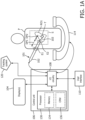
- the rigid proximal portion 102 and the flexible distal portion 103 of the robot 101 may be operated under control of a control unit 106, as discussed below, or in an embodiment, the rigid proximal portion 102 may be a handheld introducer manually positioned at the first entry location E1 to the body of the patient P and manipulated by the clinician (user).
- the rigid proximal portion 102 of the robot 101 may have a remote center of motion (RCM) at the first entry location E1, enabling the rigid proximal portion 102 to pivot around the first entry location E1 ("pivot point").
- RCM remote center of motion
- the RCM located at the surface of the body of the patient P, and is configured for movement along a number of degrees of freedom.
- the rigid proximal portion 102 of the robot 101 may have a RCM at the second entry location E2, such that the RCM is located at the surface of the RIO, enabling movement along a number of degrees of freedom.
- the opening at the first entry location E1 may be smaller than in the embodiment where the RCM is located at the surface of the RIO. This is because, when the RCM is located at the surface of the RIO, the rigid proximal portion 102 pivots inside the patient P, and thus there must be room at the first entry location E1 for the rigid proximal portion 102 to move distances at the surface of the body of the patient P corresponding to the angle of the movement and the distance between the first entry location E1 and the second entry location E2.
- the rigid proximal portion 102 is manipulated by instructions from the control unit 106, received via an input/output (I/O) circuit 108, or manipulated manually by the clinician, to guide the rigid proximal portion 102 to the desired region of interest ROI in the surgical site S.
- I/O input/output
- the surgical robot system 100 comprises a display 104, which provides real-time images of the location of at least a portion of the rigid proximal portion 102 and the flexible distal portion 103 of the robot 101 within the patient P.
- the display 104 may receive the real-time images from the image acquisition device 114, via the I/O circuitry 108 and/or a processor 130, as described more fully below.
- the image acquisition device 114 may comprise a C-arm, for example, which is an imaging scanner intensifier, so named because of its C configuration.
- a C-arm has radiographic capabilities, and may be used for fluoroscopic imaging during surgical procedures, as is would be apparent to those skilled in the art.
- the image acquisition device 114 may comprise one of a variety of inter-operative imaging devices within the purview of one of ordinary skill in the art to provide real-time imaging. These real-time (i.e., inter-operative) images may be used in connection with the pre-operative images to effect registration as described below.
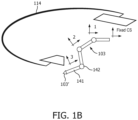
- the flexible distal portion 103 may comprise an end-effector (not shown) as desired for the particular robotic procedure.
- the end-effector connected to the flexible distal portion 103 may comprise a gripper or a tool holder.
- the flexible distal portion 103 may comprise a tool such as a laparoscopic instrument, laparoscope, a tool for screw placement, a forward-looking camera, or a needle for biopsy or therapy.
- Other surgical devices and tools within the purview of one of ordinary skill in the art are also contemplated to be used with the flexible distal portion 103.
- the display 104 comprises an output device and/or a user interface adapted for displaying images and data, as described more fully herein.
- the display 104 may include one or more displays that may be co-located near the clinician positioned adjacent to various elements of the surgical robot system 100.
- the display 104 is configured to display live and/or preoperative images of the surgical site S provided, for example, by the image acquisition device 114.
- the display 104 may output visual, audio, and/or tactile data.
- the processor 130 is therefore able to build a database essentially visually mapping interior portions of the patient P captured by the image acquisition device 114.
- an additional image acquisition device may be included to provide internal images.
- Such additional image acquisition devices may include, for example, a transesophageal echocardiography (TEE) probe or an endoscope, and the internal images may include interior portions of the patient P traversed by the additional image acquisition device.
- TEE transesophageal echocardiography
- the database built by the processor 130 may be used to determine paths from the first entry location E1 to the second entry location E2 (e.g., a first deployment path DP1 to a first target position), and from the second entry location E2 to the target T within the region of interest ROI (e.g., a second deployment path DP2 to a second target position).
- the processor 130 transmits the images to the display 104 via the I/O circuitry 108 for display.
- an endoscope for purposes of the present invention include, but are not limited to, any type of scope, flexible or rigid (e.g., endoscope, arthroscope, bronchoscope, choledochoscope, colonoscope, cystoscope, duodenoscope, gastroscope, hysteroscope, laparoscope, laryngoscope, neuroscope, otoscope, push enteroscope, rhinolaryngoscope, sigmoidoscope, sinuscope, thorascope, etc.) and any device similar to a scope that is equipped with an image system.
- the imaging is local, and surface images may be obtained optically with fiber optics, lenses, or miniaturized (e.g. CCD based) imaging systems.
- the additional image acquisition device may be connected to, and may be a component of the control unit 106.
- the additional image acquisition device provides images ultimately provided to the display 104, and may include any type of camera having a forward optical view or an oblique optical view, and may be capable of acquiring a sequence of two-dimensional digital video frames at a predefined frame rate (e.g., 30 frames per second) and capable of providing each digital video frame to the control unit 106 via the I/O circuitry 108.
- the additional image acquisition device may be positioned and oriented such that within its field of view it can capture images of the flexible distal portion 103.
- additional image acquisition device includes a camera which is actuated by a motor and can be positioned along a planned instrument path for the robot 101.
- the processor 130 may comprise one or more microprocessors that may be programmed using software (e.g., microcode) to perform various functions discussed herein. Notably, the processor 130 may comprise more than one processor or processing core. The processor 130 may for instance be a multi-core processor.
- the control unit 106 may also comprise a collection of processors within a single computer system (not shown) or distributed among multiple computer systems (not shown) associated with the surgical robot system 100. As will be appreciated, many programs have their instructions performed by the processor 130 that may be within the same computing device or which may even be distributed across multiple computing devices. Examples of components that may be employed as the processor 130 in various embodiments of the present disclosure include, but are not limited to, conventional microprocessors, microcontrol units, application specific integrated circuits (ASICs), and/or field-programmable gate arrays (FPGAs).
- ASICs application specific integrated circuits
- FPGAs field-programmable gate arrays
- the memory 134 and/or the CRM 136 may be configured to store various types of data gathered during the course of the function of the various components of the surgical robot system 100. These data include image data and tracking data gathered as described more fully below.
- the memory 134 and/or the CRM 136 may also store pre-operative data, such as pre-operative image data. As described more fully below, these data can be used to track the locations of the rigid proximal portion 102 and the flexible distal portion 103 during operation of the robot 101.
- each of the memory 134 and the CRM 136 comprises a non-transitory computer readable medium, which stores machine readable instructions configured to be executed by the processor 130 to control the surgical robot system 100, and to store various data, including image data and tracking data.
- Examples of a hardware interface include, but are not limited to: a universal serial bus, IEEE 1394 port, parallel port, IEEE 1284 port, serial port, RS-232 port, IEEE-488 port, Bluetooth connection, Wireless local area network connection, TCP/IP connection, Ethernet connection, control voltage interface, MIDI interface, analog input interface, and digital input interface.
- the processor also generates a second deployment path (e.g., second deployment path DP2) based, at least in part, on the received images for the flexible distal portion 103 to follow from the second entry location E2 to the target T, and provides instructions for the controller to deploy the flexible distal portion 103 from the end of the rigid proximal portion 102 along the second deployment path.
- a second deployment path e.g., second deployment path DP2
- the operation is similar, except that the rigid proximal portion 102 pivots around the second entry location E2, requiring a larger incision fro the first entry location E1 to accommodate the pivotal movements of the rigid proximal portion 102 at the surface of the patient's body. That is, the rigid proximal portion 102 of the robot 101 is inserted into the patient P through first entry location E1, either under control of the control unit 106 or manually.
- the RCM of the rigid proximal portion 102 is located at the second entry location E2 on the surface of the region of interest ROI (e.g., an internal organ) within the patient's body, enabling the rigid proximal portion 102 to pivot among various angles (e.g., B1 and B2) relative to the surface of the region of interest ROI, thereby positioning the rigid proximal portion 102 to accommodate access by the flexible distal portion 103 to the target T in the region of interest ROI.
- ROI e.g., an internal organ
- a processor receives images from at least one image acquisition device (e.g., image acquisition device 114), generates a first deployment path based, at least in part, on the received images for the rigid proximal portion 102 to follow from the first entry location E1 to the second entry location E2, and provides instructions for a controller (e.g., control unit 106) to deploy the rigid proximal portion 102 along the first deployment path.
- image acquisition device e.g., image acquisition device 114
- a controller e.g., control unit 106
- FIG. 3 is a perspective view a surgical robot system for accessing a patient's heart, in accordance with a representative embodiment, in which the surgical robot system is used for an aortic valve replacement.
- the aortic valve replacement is an example of implementing the surgical robot system 101, which may be used for other types of medical procedures and surgeries without departing from the scope of the present teachings.
- surgical robot system 301 includes robot 101 with rigid proximal portion 102 and flexible distal portion 103.
- the RCM of the rigid proximal portion 102 is at the surface of the body of patient P.
- the rigid proximal portion 102 is manipulated, e.g., by a controller or manually, through first entry location E1 (e.g., an initial incision is made between two ribs) and enters the heart 301 through second entry location E2.
- the flexible distal portion 103 deploys through the rigid proximal portion 102, and is used to deploy a prosthetic valve into ventricle 305.
- the surgical robot system 301 further includes image acquisition device 314, which is a C-arm imaging system with image detector 314-1 and source 314-2.
- the image acquisition device 314 provides live and/or preoperative images of the heart 310 and the robot 101.
- the image data, together with tracking data from a tracking system e.g., tracking system 120
- a processor e.g., processor 130
- TEE transesophageal echocardiography
- FIG. 4 is a flowchart illustrating operations of a method 400 of control and guidance which may be performed by the surgical robot system 100, in accordance with a representative embodiment.
- method 400 is performed by the version of surgical robot system 100 is illustrated in FIG. 1A , thus all or part of the operations depicted in FIG. 4 may be performed by or under control of the processor 130.
- the method may be implemented using other embodiments of the surgical robot system, without departing from the scope of the present teachings.
- the rigid proximal portion 102 is configured such that the RCM is positioned at the first entry point E1 to the patient P (e.g., between the ribs). This configuration minimizes injury to ribs and chest muscles, but somewhat limits motion of the rigid proximal portion 102 to be performed before the flexible distal portion 103 is deployed.
- an initial position (on the patient's body) of the rigid proximal portion 102 is determined.
- the rigid proximal portion 102 is aligned with the initial position, e.g., by the clinician, using either manual or master/slave control of the rigid proximal portion, to position the rigid proximal portion 102 in the body cavity through the first entry point E1.
- the rigid proximal portion 102 is advanced through the body cavity toward the surgical site S. Once the rigid proximal portion 102 is visible in image(s) provided by the image acquisition device 114, such as x-ray images, the rigid proximal portion 102 is registered to the region of interest ROI (e.g., the patient's heart, in this example) using any method, including registration methods provided herein. For example, real-time tracking of surgical tools relative to a pre-operative surgical plan and intra-operative images involving an image-based registration and tool tracking registration are disclosed in commonly owned U.S. Patent Application Publication 2012/0294498 by Popovic (November 22, 2012 ).
- a first deployment path DP1 is generated for the rigid proximal portion 102 from the RCM (e.g., the first entry location E1) to an entry point of the region of interest ROI (e.g., the second entry location E2).
- the first deployment path DP1 may be generated by the processor 130 based on known locations of the first entry location E1 and the location of the boundaries of the region of interest ROI, for example, through images provided by the image acquisition device 114.
- the first deployment path DP1 may be determined by the clinician, for example, using data and/or images provided by the processor 130 and/or the image acquisition device 114.
- first guidance information may be generated for positioning the rigid proximal portion 102 along the first deployment path DP1.
- guidance information includes registration of the robot 101 to the image acquisition device 114, and may provide data such as coordinates in a three-dimensional space, corresponding to a determined deployment path within the patient P and commands to maneuver the robot to the coordinates.
- the clinician may manually move the rigid proximal portion 102 along the determined first deployment path DP1, e.g., using the live images from the image acquisition device 114.
- the flexible distal portion 103 is deployed into the region of interest ROI through the rigid proximal portion 102. Since, in the present example, the flexible distal portion 103 is introduced in the heart, it is visible under x-ray and ultrasound.
- the flexible distal portion 103 may be registered to x-ray from the image acquisition device 114, as well as to ultrasound from an ultrasound TEE probe (optional), such as TEE probe 310 discussed above, using EchoNavigator ® available from Philips Electronics, for example, in order to provide close-up live imaging of the heart.
- a second deployment path DP2 is generated in operation 407 for the flexible distal portion 103 from the tracked location of the flexible distal portion 103 to the target T (e.g., the heart muscle).
- the second deployment path DP2 may be generated by the processor 130 based on known locations of the second entry location E2 and the location of the target T, for example, through images provided by the image acquisition device 114.
- a distal tip of the flexible distal portion 103 is moved along the second deployment path DP2 to the target T.
- second guidance information may be generated for positioning the flexible distal portion 103 along the second deployment path DP2 in order to move the flexible distal portion 103.
- the valve annulus of the aortic valve of the heart may be detected in at least one of the x-ray and ultrasound images for generating the second deployment path DP2 and/or the second guidance information, and the flexible distal portion of the robot 101 may be controlled using such live images to position the distal tip of the flexible distal portion at or perpendicular to the annulus. Once the position is reached, the therapy device is deployed.
- therapy device may include a balloon catheter and a prosthetic valve passed the left ventricle of the heart, and using a pusher and sleeve to advance the balloon catheter and prosthetic valve mounted thereon in order to properly position the prosthetic valve within the aortic annulus.
- a last operation is added to facilitate repositioning of the flexible distal portion 103.
- the rigid proximal portion 102 of the robot 101 may reposition the flexible distal portion device to a reachable position by pivoting around the second entry location E2 to the region of interest ROI.
- the method 400 may further include transmitting the medical imagery to display 104.
- the display arrangement is broadly defined herein as any device structurally configured for displaying images and tracked surgical tools and other end-effectors under any suitable technique. Examples of a display include a computer monitor, a television screen, a touch screen, a projector, and head-mounted display (HMD).
- HMD head-mounted display
- the present teachings are part of a technological progression towards smart systems and devices. Possible applications include augmented reality of live video with preoperative CT, surgical navigation, especially in minimally invasive surgery where the workspace is obscured from view, and finding anatomical targets and tumors.
Landscapes
- Health & Medical Sciences (AREA)
- Life Sciences & Earth Sciences (AREA)
- Surgery (AREA)
- Engineering & Computer Science (AREA)
- Nuclear Medicine, Radiotherapy & Molecular Imaging (AREA)
- Animal Behavior & Ethology (AREA)
- Public Health (AREA)
- Heart & Thoracic Surgery (AREA)
- Medical Informatics (AREA)
- Molecular Biology (AREA)
- Veterinary Medicine (AREA)
- General Health & Medical Sciences (AREA)
- Biomedical Technology (AREA)
- Robotics (AREA)
- Gynecology & Obstetrics (AREA)
- Radiology & Medical Imaging (AREA)
- Oral & Maxillofacial Surgery (AREA)
- Pathology (AREA)
- Manipulator (AREA)
- Endoscopes (AREA)
- Prostheses (AREA)
Applications Claiming Priority (2)
| Application Number | Priority Date | Filing Date | Title |
|---|---|---|---|
| US201662309758P | 2016-03-17 | 2016-03-17 | |
| PCT/EP2017/056435 WO2017158180A1 (en) | 2016-03-17 | 2017-03-17 | Control unit, system and method for controlling hybrid robot having rigid proximal portion and flexible distal portion |
Publications (2)
| Publication Number | Publication Date |
|---|---|
| EP3429496A1 EP3429496A1 (en) | 2019-01-23 |
| EP3429496B1 true EP3429496B1 (en) | 2025-07-09 |
Family
ID=58347403
Family Applications (1)
| Application Number | Title | Priority Date | Filing Date |
|---|---|---|---|
| EP17711204.2A Active EP3429496B1 (en) | 2016-03-17 | 2017-03-17 | Control unit, system and method for controlling hybrid robot having rigid proximal portion and flexible distal portion |
Country Status (5)
| Country | Link |
|---|---|
| US (1) | US12239380B2 (enExample) |
| EP (1) | EP3429496B1 (enExample) |
| JP (1) | JP7041068B6 (enExample) |
| CN (1) | CN109069207B (enExample) |
| WO (1) | WO2017158180A1 (enExample) |
Families Citing this family (15)
| Publication number | Priority date | Publication date | Assignee | Title |
|---|---|---|---|---|
| US12303203B1 (en) * | 2011-12-19 | 2025-05-20 | Birider Boveja | Methods and system for atrial fibrillation ablation using balloon based catheters and utilizing medical images (CT or MRI in segments) based cardiac mapping and/or utilizing virtual reality (VR), and/or augmented reality (AR), and/or mixed reality (MR) for aiding in cardiac procedures |
| US10512511B2 (en) | 2013-07-24 | 2019-12-24 | Centre For Surgical Invention And Innovation | Multi-function mounting interface for an image-guided robotic system and quick release interventional toolset |
| EP3397185A1 (en) * | 2015-12-29 | 2018-11-07 | Koninklijke Philips N.V. | System, controller and method using virtual reality device for robotic surgery |
| FR3073135B1 (fr) * | 2017-11-09 | 2019-11-15 | Quantum Surgical | Dispositif robotise pour une intervention medicale mini-invasive sur des tissus mous |
| WO2019091962A1 (en) | 2017-11-13 | 2019-05-16 | Koninklijke Philips N.V. | Multi-stage robot for anatomical structure interventions |
| IT201800005507A1 (it) * | 2018-05-18 | 2019-11-18 | Robot per chirurgia mininvasiva | |
| CN110537983B (zh) * | 2019-09-26 | 2021-05-14 | 重庆博仕康科技有限公司 | 光磁一体穿刺手术导航平台 |
| US12329461B2 (en) * | 2019-12-02 | 2025-06-17 | Think Surgical, Inc. | System and method for aligning a tool with an axis to perform a medical procedure |
| KR20220131311A (ko) * | 2020-01-23 | 2022-09-27 | 프로맥소 인크. | 생검용 mri 안내형 로봇 시스템 및 방법 |
| DE102020212086A1 (de) * | 2020-09-25 | 2022-03-31 | Siemens Healthcare Gmbh | Ermitteln der Qualität einer Positionierung eines in einen Patientenkörper eingeführten Objekts |
| EP4016455A1 (en) * | 2020-12-16 | 2022-06-22 | Koninklijke Philips N.V. | Predictive motion mapping for flexible devices |
| CN112932669B (zh) * | 2021-01-18 | 2024-03-15 | 广州市微眸医疗器械有限公司 | 一种执行视网膜层防渗漏隧道的机械臂控制方法 |
| CN115120349B (zh) * | 2021-03-24 | 2025-09-05 | 上海微创医疗机器人(集团)股份有限公司 | 计算机可读存储介质、电子设备及手术机器人系统 |
| CN115703227B (zh) * | 2021-08-03 | 2025-06-03 | 武汉联影智融医疗科技有限公司 | 机器人的控制方法、机器人以及计算机可读存储介质 |
| EP4663147A1 (en) * | 2024-06-12 | 2025-12-17 | Caranx Medical | A medical device controller and medical system comprising the device controller |
Family Cites Families (47)
| Publication number | Priority date | Publication date | Assignee | Title |
|---|---|---|---|---|
| US6246898B1 (en) * | 1995-03-28 | 2001-06-12 | Sonometrics Corporation | Method for carrying out a medical procedure using a three-dimensional tracking and imaging system |
| US6468265B1 (en) * | 1998-11-20 | 2002-10-22 | Intuitive Surgical, Inc. | Performing cardiac surgery without cardioplegia |
| US7130700B2 (en) * | 2002-11-19 | 2006-10-31 | Medtronic, Inc. | Multilumen body for an implantable medical device |
| US7697972B2 (en) * | 2002-11-19 | 2010-04-13 | Medtronic Navigation, Inc. | Navigation system for cardiac therapies |
| EP1720480A1 (en) | 2004-03-05 | 2006-11-15 | Hansen Medical, Inc. | Robotic catheter system |
| AU2004324043A1 (en) * | 2004-10-02 | 2006-04-20 | Christoph Hans Huber | Methods and devices for repair or replacement of heart valves or adjacent tissue without the need for full cardiopulmonary support |
| US7963288B2 (en) * | 2005-05-03 | 2011-06-21 | Hansen Medical, Inc. | Robotic catheter system |
| US8790396B2 (en) * | 2005-07-27 | 2014-07-29 | Medtronic 3F Therapeutics, Inc. | Methods and systems for cardiac valve delivery |
| US8764820B2 (en) | 2005-11-16 | 2014-07-01 | Edwards Lifesciences Corporation | Transapical heart valve delivery system and method |
| US10258425B2 (en) * | 2008-06-27 | 2019-04-16 | Intuitive Surgical Operations, Inc. | Medical robotic system providing an auxiliary view of articulatable instruments extending out of a distal end of an entry guide |
| WO2008086434A2 (en) * | 2007-01-09 | 2008-07-17 | Cyberheart, Inc. | Depositing radiation in heart muscle under ultrasound guidance |
| US9370627B2 (en) * | 2007-02-20 | 2016-06-21 | Siemens Medical Solutions Usa, Inc. | Needle guidance with a dual-headed laser |
| US9084623B2 (en) * | 2009-08-15 | 2015-07-21 | Intuitive Surgical Operations, Inc. | Controller assisted reconfiguration of an articulated instrument during movement into and out of an entry guide |
| EP2626006B1 (en) * | 2007-08-14 | 2019-10-09 | Koninklijke Philips N.V. | Robotic instrument systems utilizing optical fiber sensors |
| US8315689B2 (en) * | 2007-09-24 | 2012-11-20 | MRI Interventions, Inc. | MRI surgical systems for real-time visualizations using MRI image data and predefined data of surgical tools |
| US8282653B2 (en) * | 2008-03-24 | 2012-10-09 | Board Of Regents Of The University Of Nebraska | System and methods for controlling surgical tool elements |
| US9161817B2 (en) * | 2008-03-27 | 2015-10-20 | St. Jude Medical, Atrial Fibrillation Division, Inc. | Robotic catheter system |
| WO2009144730A1 (en) * | 2008-05-28 | 2009-12-03 | Technion Research & Development Foundation Ltd. | Ultrasound guided robot for flexible needle steering |
| US8535336B2 (en) * | 2008-06-25 | 2013-09-17 | Koninklijke Philips N.V. | Nested cannulae for minimally invasive surgery |
| US20110282151A1 (en) | 2008-10-20 | 2011-11-17 | Koninklijke Philips Electronics N.V. | Image-based localization method and system |
| US8252049B2 (en) * | 2008-11-03 | 2012-08-28 | Siemens Aktiengesellschaft | Method for therapy of heart valves with a robot-based X-ray device |
| US8784800B2 (en) * | 2009-03-09 | 2014-07-22 | Medtronic, Inc. | Method of delivering cell therapy to a target site |
| US20110071541A1 (en) | 2009-09-23 | 2011-03-24 | Intuitive Surgical, Inc. | Curved cannula |
| JP5795599B2 (ja) | 2010-01-13 | 2015-10-14 | コーニンクレッカ フィリップス エヌ ヴェ | 内視鏡手術のための画像統合ベースレジストレーション及びナビゲーション |
| GB2477118A (en) * | 2010-01-22 | 2011-07-27 | Reckitt Benckiser Corporate Services Ltd | Dynamically adjustable state transition timer |
| CA2796269A1 (en) * | 2010-04-13 | 2011-10-20 | Sentreheart, Inc. | Methods and devices for accessing and delivering devices to a heart |
| BR112014005451B1 (pt) | 2011-09-13 | 2021-11-09 | Koninklijke Philips N.V. | Sistema de registro |
| RU2014122527A (ru) * | 2011-11-04 | 2015-12-10 | Те Джонс Хопкинс Юниверсити | Стационарный робот для ручных микроманипуляций |
| US9956042B2 (en) * | 2012-01-13 | 2018-05-01 | Vanderbilt University | Systems and methods for robot-assisted transurethral exploration and intervention |
| JP6122875B2 (ja) | 2012-02-06 | 2017-04-26 | コーニンクレッカ フィリップス エヌ ヴェKoninklijke Philips N.V. | 血管ツリー画像内での見えない分岐部の検出 |
| WO2013156893A1 (en) * | 2012-04-19 | 2013-10-24 | Koninklijke Philips N.V. | Guidance tools to manually steer endoscope using pre-operative and intra-operative 3d images |
| US10039473B2 (en) * | 2012-05-14 | 2018-08-07 | Intuitive Surgical Operations, Inc. | Systems and methods for navigation based on ordered sensor records |
| JP2015523133A (ja) | 2012-06-15 | 2015-08-13 | コーニンクレッカ フィリップス エヌ ヴェ | 内視鏡低侵襲手術のための誘導切開計画 |
| US9603666B2 (en) | 2012-08-02 | 2017-03-28 | Koninklijke Philips N.V. | Controller definition of a robotic remote center of motion |
| KR102038632B1 (ko) * | 2012-11-06 | 2019-10-30 | 삼성전자주식회사 | 수술용 인스트루먼트, 서포터 장치, 및 수술 로봇 시스템 |
| US10588597B2 (en) * | 2012-12-31 | 2020-03-17 | Intuitive Surgical Operations, Inc. | Systems and methods for interventional procedure planning |
| US9600138B2 (en) * | 2013-03-15 | 2017-03-21 | Synaptive Medical (Barbados) Inc. | Planning, navigation and simulation systems and methods for minimally invasive therapy |
| US9592095B2 (en) * | 2013-05-16 | 2017-03-14 | Intuitive Surgical Operations, Inc. | Systems and methods for robotic medical system integration with external imaging |
| KR102354675B1 (ko) * | 2013-08-15 | 2022-01-24 | 인튜어티브 서지컬 오퍼레이션즈 인코포레이티드 | 의료 절차 확인을 위한 시스템 및 방법 |
| WO2015128766A1 (en) * | 2014-02-26 | 2015-09-03 | Koninklijke Philips N.V. | System for performing extraluminal coronary bypass and method of operation thereof |
| US10888307B2 (en) * | 2014-02-26 | 2021-01-12 | Koninklijke Philips N.V. | System for performing intraluminal coronary and method of operation thereof |
| US11058140B2 (en) | 2014-09-19 | 2021-07-13 | Koninklijke Philips N.V. | Apparatus and method for roasting coffee beans, and coffee machine |
| US9737371B2 (en) * | 2014-09-30 | 2017-08-22 | Auris Surgical Robotics, Inc. | Configurable robotic surgical system with virtual rail and flexible endoscope |
| JP6505444B2 (ja) * | 2015-01-16 | 2019-04-24 | キヤノンメディカルシステムズ株式会社 | 観察装置 |
| US10143526B2 (en) * | 2015-11-30 | 2018-12-04 | Auris Health, Inc. | Robot-assisted driving systems and methods |
| JP6547849B2 (ja) * | 2015-12-28 | 2019-07-24 | 株式会社島津製作所 | 放射線装置 |
| JP2020527095A (ja) * | 2017-07-13 | 2020-09-03 | マイトリックス, インコーポレイテッド | 心臓手術のために左心房にアクセスするためのデバイスおよび方法 |
-
2017
- 2017-03-17 US US16/084,746 patent/US12239380B2/en active Active
- 2017-03-17 CN CN201780017871.6A patent/CN109069207B/zh active Active
- 2017-03-17 EP EP17711204.2A patent/EP3429496B1/en active Active
- 2017-03-17 JP JP2018548395A patent/JP7041068B6/ja active Active
- 2017-03-17 WO PCT/EP2017/056435 patent/WO2017158180A1/en not_active Ceased
Also Published As
| Publication number | Publication date |
|---|---|
| EP3429496A1 (en) | 2019-01-23 |
| CN109069207A (zh) | 2018-12-21 |
| JP2019512315A (ja) | 2019-05-16 |
| WO2017158180A1 (en) | 2017-09-21 |
| US20190069955A1 (en) | 2019-03-07 |
| US12239380B2 (en) | 2025-03-04 |
| JP7041068B2 (ja) | 2022-03-23 |
| JP7041068B6 (ja) | 2022-05-30 |
| CN109069207B (zh) | 2021-09-10 |
Similar Documents
| Publication | Publication Date | Title |
|---|---|---|
| EP3429496B1 (en) | Control unit, system and method for controlling hybrid robot having rigid proximal portion and flexible distal portion | |
| US10786319B2 (en) | System, control unit and method for control of a surgical robot | |
| US11413099B2 (en) | System, controller and method using virtual reality device for robotic surgery | |
| US12295672B2 (en) | Robotic systems for determining a roll of a medical device in luminal networks | |
| US10945796B2 (en) | Robotic control of surgical instrument visibility | |
| US11284777B2 (en) | Robotic control of an endoscope from anatomical features | |
| AU2019347754A1 (en) | Robotic systems and methods for concomitant endoscopic and percutaneous medical procedures | |
| US20230363826A1 (en) | Pre-docking pose optimization | |
| US20240349984A1 (en) | Systems and methods for generating images of a selected imaging plane using a forward-facing imaging array |
Legal Events
| Date | Code | Title | Description |
|---|---|---|---|
| STAA | Information on the status of an ep patent application or granted ep patent |
Free format text: STATUS: UNKNOWN |
|
| STAA | Information on the status of an ep patent application or granted ep patent |
Free format text: STATUS: THE INTERNATIONAL PUBLICATION HAS BEEN MADE |
|
| PUAI | Public reference made under article 153(3) epc to a published international application that has entered the european phase |
Free format text: ORIGINAL CODE: 0009012 |
|
| STAA | Information on the status of an ep patent application or granted ep patent |
Free format text: STATUS: REQUEST FOR EXAMINATION WAS MADE |
|
| 17P | Request for examination filed |
Effective date: 20181017 |
|
| AK | Designated contracting states |
Kind code of ref document: A1 Designated state(s): AL AT BE BG CH CY CZ DE DK EE ES FI FR GB GR HR HU IE IS IT LI LT LU LV MC MK MT NL NO PL PT RO RS SE SI SK SM TR |
|
| AX | Request for extension of the european patent |
Extension state: BA ME |
|
| DAV | Request for validation of the european patent (deleted) | ||
| DAX | Request for extension of the european patent (deleted) | ||
| RAP1 | Party data changed (applicant data changed or rights of an application transferred) |
Owner name: KONINKLIJKE PHILIPS N.V. |
|
| STAA | Information on the status of an ep patent application or granted ep patent |
Free format text: STATUS: EXAMINATION IS IN PROGRESS |
|
| 17Q | First examination report despatched |
Effective date: 20211027 |
|
| GRAP | Despatch of communication of intention to grant a patent |
Free format text: ORIGINAL CODE: EPIDOSNIGR1 |
|
| STAA | Information on the status of an ep patent application or granted ep patent |
Free format text: STATUS: GRANT OF PATENT IS INTENDED |
|
| INTG | Intention to grant announced |
Effective date: 20250206 |
|
| GRAS | Grant fee paid |
Free format text: ORIGINAL CODE: EPIDOSNIGR3 |
|
| GRAA | (expected) grant |
Free format text: ORIGINAL CODE: 0009210 |
|
| STAA | Information on the status of an ep patent application or granted ep patent |
Free format text: STATUS: THE PATENT HAS BEEN GRANTED |
|
| AK | Designated contracting states |
Kind code of ref document: B1 Designated state(s): AL AT BE BG CH CY CZ DE DK EE ES FI FR GB GR HR HU IE IS IT LI LT LU LV MC MK MT NL NO PL PT RO RS SE SI SK SM TR |
|
| REG | Reference to a national code |
Ref country code: GB Ref legal event code: FG4D |
|
| REG | Reference to a national code |
Ref country code: CH Ref legal event code: EP |
|
| REG | Reference to a national code |
Ref country code: IE Ref legal event code: FG4D |
|
| REG | Reference to a national code |
Ref country code: DE Ref legal event code: R096 Ref document number: 602017090434 Country of ref document: DE |
|
| REG | Reference to a national code |
Ref country code: NL Ref legal event code: MP Effective date: 20250709 |
|
| PG25 | Lapsed in a contracting state [announced via postgrant information from national office to epo] |
Ref country code: PT Free format text: LAPSE BECAUSE OF FAILURE TO SUBMIT A TRANSLATION OF THE DESCRIPTION OR TO PAY THE FEE WITHIN THE PRESCRIBED TIME-LIMIT Effective date: 20251110 |