EP3429470B1 - Verfahren zur kalkulation von druckabfall - Google Patents
Verfahren zur kalkulation von druckabfall Download PDFInfo
- Publication number
- EP3429470B1 EP3429470B1 EP17713378.2A EP17713378A EP3429470B1 EP 3429470 B1 EP3429470 B1 EP 3429470B1 EP 17713378 A EP17713378 A EP 17713378A EP 3429470 B1 EP3429470 B1 EP 3429470B1
- Authority
- EP
- European Patent Office
- Prior art keywords
- blood
- outlet
- velocity
- inlet
- data
- Prior art date
- Legal status (The legal status is an assumption and is not a legal conclusion. Google has not performed a legal analysis and makes no representation as to the accuracy of the status listed.)
- Active
Links
Images







Classifications
-
- A—HUMAN NECESSITIES
- A61—MEDICAL OR VETERINARY SCIENCE; HYGIENE
- A61B—DIAGNOSIS; SURGERY; IDENTIFICATION
- A61B5/00—Measuring for diagnostic purposes; Identification of persons
- A61B5/02—Detecting, measuring or recording for evaluating the cardiovascular system, e.g. pulse, heart rate, blood pressure or blood flow
- A61B5/021—Measuring pressure in heart or blood vessels
-
- A—HUMAN NECESSITIES
- A61—MEDICAL OR VETERINARY SCIENCE; HYGIENE
- A61B—DIAGNOSIS; SURGERY; IDENTIFICATION
- A61B5/00—Measuring for diagnostic purposes; Identification of persons
- A61B5/02—Detecting, measuring or recording for evaluating the cardiovascular system, e.g. pulse, heart rate, blood pressure or blood flow
- A61B5/026—Measuring blood flow
- A61B5/0263—Measuring blood flow using NMR
-
- A—HUMAN NECESSITIES
- A61—MEDICAL OR VETERINARY SCIENCE; HYGIENE
- A61B—DIAGNOSIS; SURGERY; IDENTIFICATION
- A61B5/00—Measuring for diagnostic purposes; Identification of persons
- A61B5/05—Detecting, measuring or recording for diagnosis by means of electric currents or magnetic fields; Measuring using microwaves or radio waves
- A61B5/055—Detecting, measuring or recording for diagnosis by means of electric currents or magnetic fields; Measuring using microwaves or radio waves involving electronic [EMR] or nuclear [NMR] magnetic resonance, e.g. magnetic resonance imaging
-
- A—HUMAN NECESSITIES
- A61—MEDICAL OR VETERINARY SCIENCE; HYGIENE
- A61B—DIAGNOSIS; SURGERY; IDENTIFICATION
- A61B5/00—Measuring for diagnostic purposes; Identification of persons
- A61B5/72—Signal processing specially adapted for physiological signals or for diagnostic purposes
- A61B5/7235—Details of waveform analysis
- A61B5/7242—Details of waveform analysis using integration
-
- A—HUMAN NECESSITIES
- A61—MEDICAL OR VETERINARY SCIENCE; HYGIENE
- A61B—DIAGNOSIS; SURGERY; IDENTIFICATION
- A61B8/00—Diagnosis using ultrasonic, sonic or infrasonic waves
- A61B8/04—Measuring blood pressure
-
- A—HUMAN NECESSITIES
- A61—MEDICAL OR VETERINARY SCIENCE; HYGIENE
- A61B—DIAGNOSIS; SURGERY; IDENTIFICATION
- A61B8/00—Diagnosis using ultrasonic, sonic or infrasonic waves
- A61B8/06—Measuring blood flow
-
- A—HUMAN NECESSITIES
- A61—MEDICAL OR VETERINARY SCIENCE; HYGIENE
- A61B—DIAGNOSIS; SURGERY; IDENTIFICATION
- A61B8/00—Diagnosis using ultrasonic, sonic or infrasonic waves
- A61B8/48—Diagnostic techniques
- A61B8/488—Diagnostic techniques involving Doppler signals
-
- A—HUMAN NECESSITIES
- A61—MEDICAL OR VETERINARY SCIENCE; HYGIENE
- A61B—DIAGNOSIS; SURGERY; IDENTIFICATION
- A61B8/00—Diagnosis using ultrasonic, sonic or infrasonic waves
- A61B8/52—Devices using data or image processing specially adapted for diagnosis using ultrasonic, sonic or infrasonic waves
- A61B8/5215—Devices using data or image processing specially adapted for diagnosis using ultrasonic, sonic or infrasonic waves involving processing of medical diagnostic data
- A61B8/5223—Devices using data or image processing specially adapted for diagnosis using ultrasonic, sonic or infrasonic waves involving processing of medical diagnostic data for extracting a diagnostic or physiological parameter from medical diagnostic data
-
- A—HUMAN NECESSITIES
- A61—MEDICAL OR VETERINARY SCIENCE; HYGIENE
- A61B—DIAGNOSIS; SURGERY; IDENTIFICATION
- A61B2576/00—Medical imaging apparatus involving image processing or analysis
- A61B2576/02—Medical imaging apparatus involving image processing or analysis specially adapted for a particular organ or body part
- A61B2576/023—Medical imaging apparatus involving image processing or analysis specially adapted for a particular organ or body part for the heart
-
- G—PHYSICS
- G16—INFORMATION AND COMMUNICATION TECHNOLOGY [ICT] SPECIALLY ADAPTED FOR SPECIFIC APPLICATION FIELDS
- G16H—HEALTHCARE INFORMATICS, i.e. INFORMATION AND COMMUNICATION TECHNOLOGY [ICT] SPECIALLY ADAPTED FOR THE HANDLING OR PROCESSING OF MEDICAL OR HEALTHCARE DATA
- G16H30/00—ICT specially adapted for the handling or processing of medical images
- G16H30/40—ICT specially adapted for the handling or processing of medical images for processing medical images, e.g. editing
Definitions
- the present invention generally relates to methods for estimating the pressure drop through a vessel, and specifically to the estimation of blood pressure drop through a blood vessel based on measurements of velocity obtained from various medical imaging modalities.
- Pressure drops or differences measured over vascular segments are widely used clinically as biomarkers for a number of cardiovascular disorders (Baumgartner, Hung, Bermejo, Chambers, Evangelista, Griffin, lung, Otto, Pellikka, Qui ⁇ ones, 2009, Sawaya, Stewart, Babaliaros, 2012 and Vahanian, Baumgartner, Bax, Butchart, Dion, Filippatos, Flachskampf, Hall, lung, Kasprzak, Nataf, Tornos, Torracca, Wenink, 2007).
- aortic coarctation (CoA), where the pressure drop is used as a diagnostic metric to risk stratify patients undergoing surgery (Jenkins, Ward, 1999 and Oshinski, Parks, Markou, Bergman, Larson, Ku, Mukundan, Pettigrew, 1997) and to evaluate patients after stenting (Tan et al., 2005).
- pressure based metrics in the clinic include the transvalvular drop - an accepted metric to classify the severity of aortic valve stenosis (Baumgartner, Hung, Bermejo, Chambers, Evangelista, Griffin, Iung, Otto, Pellikka, Qui ⁇ ones, 2009, De Bruyne, Manoharan, Pijls, Verhamme, Madaric, Bartunek, Vanderheyden, Heyndrickx, 2006 and Feldman, 2006), the Left-Ventricle Outflow Tract (LVOT) pressure drop - used to define the guidelines for the treatment of Hypertrophic Cardiomyopathy (HCM) (Gersh et al., 2011), and the transstenotic pressure difference in the coronary artery - used to quantify the Fractional Flow Reserve (FFR) (Deng et al., 2014).
- HCM Hypertrophic Cardiomyopathy
- FFR Fractional Flow Reserve
- Pressure catheterization has seen significant improvement in terms of probe sensitivity (de Vecchi, Clough, Gaddum, Rutten, Lamata, Schaeffter, Nordsletten, Smith, 2014, Garcia, Carrozza, 2007 and Iwasaki, Kusachi, 2009) and surgical administration, making it the gold standard in pressure drop measurement.
- probe sensitivity de Vecchi, Clough, Gaddum, Rutten, Lamata, Schaeffter, Nordsletten, Smith, 2014, Garcia, Carrozza, 2007 and Iwasaki, Kusachi, 2009
- application of pressure catheterization is limited to specific cohorts of patients due to its intrinsic invasiveness and associated risks and cost.
- Doppler echocardiography was developed.
- the pressure difference is estimated from the peak velocity magnitude acquired along the direction of an ultrasound beam through a simplified Bernoulli formulation (Hatle, Brubakk, Tromsdal, Angelsen, 1978 and Oshinski, Parks, Markou, Bergman, Larson, Ku, Mukundan, Pettigrew, 1997). While useful for patient stratification, the accuracy of this approach is limited by operator dependence and the mathematical assumptions, which rely on neglecting transient effects and viscous losses on the flow (Holen, Simonsen, 1979, Laske, Jenni, Maloigne, Vassalli, Bertel, Turina, 1996 and Zhang, Nitter-Hauge, 1985).
- the paper " Non-invasive pressure difference estimation from PC-MRI using the work-energy equation", Medical Image Analysis, Vol. 26, pp.159-172, Dec 2015", by Donati et al., discloses a Work-Energy Relative Pressure (WERP) formulation for determining a pressure drop across a vascular region with inlet and outlet planes, where the determination of the pressure drop requires the velocity profile across the entire domain between the inlet and outlet planes in the vascular region.
- WERP Work-Energy Relative Pressure
- the claimed invention relates to two simplified approaches for pressure estimation, which require less information than the WERP method, and as a consequence can be used with data from other imaging modalities other than 4D PC-MRI, and in particular using 3D Doppler echocardiographic (ECG) images or 2D PC-MRI for the first simplified approach according to claim 1, or even Doppler ECG images from conventional 2D probes for the second simplified approach according to claim 4.
- ECG Doppler echocardiographic
- the techniques can also be applied to velocity fields reconstructed from compound ECG, or from speckle/contrast tracking in ultrafast ECG.
- 2D and 3D ECG imaging is much more prevalent in clinical settings than 4D PC-MRI, the simplified approaches have significantly more widespread application than the full WERP approach.
- a method of determining pressure difference across a tube arising from fluid flow within the tube comprising: obtaining three-dimensional time dependent fluid velocity data at a plurality of points along the tube; processing the three-dimensional time dependent fluid velocity data to determine: i) a flow rate (Q) of the fluid through the tube; ii) the kinetic energy (K) of the fluid flow through the tube; iii) an advective energy rate (A) of the fluid flow through the tube; and iv) a viscous dissipation rate (V) pertaining to the fluid flow; and calculating the pressure difference in dependence on all of the flow rate (Q), kinetic energy (K), advective energy rate (A), and viscous dissipation rate (V).
- a further example useful to understand the claimed invention provides a method of determining pressure difference across a tube arising from fluid flow within the tube, comprising: obtaining fluid velocity data only at the outlet of the tube, (which is a valid assumption when the velocities at the inlet are negligible compared to outlet velocities); processing the fluid velocity data to determine: i) a flow rate (Q) of the fluid through the tube; and ii) an advective energy rate (A) of the fluid flow through the tube but only considering the outlet; and calculating the pressure difference in dependence on both of the flow rate (Q), and the advective energy rate (A), without considering a viscous dissipation rate (V) and the kinetic energy (K) of the fluid flow through the tube.
- the disclosure also provides a set of methods of determining the advective energy rate (A) in all previous embodiments adapted to the resolution and availability of data depending on the imaging modality.
- the methods comprise: (a) a method that uses data from the complete cross-section of the inlet or outlet plane of the tube, and each data point is the complete 3D velocity vector as originated by 4D PCMRI; (b) a method that uses data from the complete cross-section of the inlet or outlet plane of the tube, and each data point is a projector of the 3D velocity vector in the direction of the insonation line, as originated by 3D ECG; (c) a method according to claim 4 which is a second aspect of this disclosure; (d) a method that uses data from a combination of lines of the cross-section of the inlet or outlet plane of the tube, and each data point is a projection of the 3D velocity vector in the direction of the insonation line, as originated by multiple 2D ECG acquisitions.
- a method of determining pressure difference across a tube arising from fluid flow within the tube comprising: obtaining three-dimensional time dependent fluid velocity data at a plurality of points along the tube; segmenting a domain of interest in the tube for which flow information therethrough is desired defining a flow vector field w through the segmented domain, being a field that is divergence free and that has null values in the lateral walls of the tube; processing the flow vector field w and the three-dimensional time dependent fluid velocity data to determine: i) a flow rate (Qw) of the flow vector field w; ii) a surrogate kinetic energy (Kw) of the fluid flow through the tube; iii) a surrogate advective energy rate (Aw) of the fluid flow through the tube; and iv) a surrogate viscous dissipation rate (Vw) pertaining to the fluid flow; and calculating the pressure difference in dependence on all of the
- a first example useful to understand the claimed invention relates to pressure drop estimation in the heart using the full WERP approach which models the pressure drop in detail over a whole length of the blood vessel of interest
- a first embodiment of the claimed invention relates to the so-called “complete Advective WERP” approach which models the pressure drop via measurements at the inlet and outlet of the vessel only
- the second embodiment relates to a so-called “simplified advective WERP” method, which makes use of measurements at the outlet of the vessel only.
- Figure 2 illustrates the measurements and the computations required for each approach
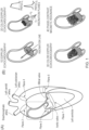
- Figure 12 gives further details of the anatomical regions of interest (particularly used in the second and third embodiments) (see Figure 1(A) ), and the different data that can be obtained from different imaging modalities ( Figure 1(B) ).
- Trans Valvular Region from the left ventricle outflow tract (LVOT) (Plane 1) to the vena contract (VC) (Plane 2); Ascending Aorta Region (AAR): from the VC to the brachiocephalic artery (Plane 3); Descending Aorta Region (DAR) from the left subclavian artery (Plane 4) to a plane at the same height of the aortic valve plane (Plane 5).
- FIG. 1(B) is shown schematics of the velocity field at the VC acquired at peak systole with different techniques and increasing level of data availability, as follows. Top left: A single velocity value is obtained from continuous 1D Doppler. Top right: A 1D velocity profile along a plane of insonation is available from a 2D color Doppler. Bottom left: A complete 2D velocity profile is available from a 3D color Doppler. Bottom right: The complete velocity vector field over the entire plane, and not simply its projection along the insonation line, is available from 4D PC-MRI.
- WERP work-energy relative pressure
- the complete advective WERP approach Given a fluid through a tubular structure, the computation of the difference of pressure between the inlet and outlet is given by the advective WERP equation, which is a simplification of the WERP equation by only taking one of the three additive terms of energy, the advective term. In more detail, this component of energy neglects the contribution of the advective energy from the lateral walls, as velocities perpendicular to the wall are small in the near-wall regions, and the computation of the pressure difference reduces to the integral of the advective energy rate at the inlet and outlet planes of the tubular structure.
- H p p i ⁇ ⁇ i ⁇ ⁇ n d x + ⁇ o ⁇ ⁇ o ⁇ ⁇ n d x + ⁇ ⁇ w p ⁇ ⁇ n d x .
- WERP Work-Energy Relative Pressure
- Vt represent the velocity image acquired at time t
- Vt ( i, j, k ) the velocity field evaluated at time t at the voxel ( i, j, k ) and ⁇ t the discrete time step between two consecutive acquisitions.
- Computation of the WERP formulation terms is performed by integrating over a voxelized version of ⁇ , I ROI .
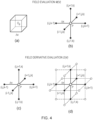
- Surface integrals are evaluated on the planes obtained by clipping the 3D mask to define inlet I in 2 D and outlet I out 2 D cross-sections (see Fig. 3 ) and the normal vectors N 2 D ( i, j ) .
- ⁇ ij is the Kronecker delta and q is a parameter used to smooth the underlying data based on O( ⁇ x 2 ) approximations to the velocity value (see Fig. 4 , which shows a schematic representation of the finite differences central stencils.
- a binary mask I ROI is defined (2), based on a thresholding of the velocity magnitude calibrated by the maximum velocity V max (including voxels with a velocity magnitude greater than SV max , with S being the segmentation thresholding parameter).
- Inlet and outlet points are manually selected by the user (3) depending on the clinical problem under investigation.
- a skeletonisation of the binary mask is then used to define the inlet and outlet planes perpendicular to the vessel (4).
- the binary masks of the raw 3D image and the inlet/outlet planes needed for the WERP computation are defined.
- Figure 5 illustrates an example imaging system that is able to apply the above described techniques to calculate blood flow through a blood vessel using the full WERP method.
- a 4D phase contrast magnetic resonance imaging (4D PC MRI) system 60 comprising MR imaging coils within which the subject is located, controlled by an MRI imaging control system 58, including an MRI controller processor 50.
- the MRI imaging control system 58 including the MRI controller processor 50 function in a conventional manner to allow 4 dimensional phase contrast magnetic resonance image data to be obtained, for example of an internal blood vessel of the subject the pressure difference across it is desired to know.
- TPD transvalvular pressure drops
- other blood vessels may also be monitored, as desired. For example, it may be possible to take into account secondary branches.
- the 4D PC MRI system 58, 60 collects 4D PC MRI data 52 of the imaging subject, which is saved for further processing and analysis. As explained previously with respect to Figure 1 , the complete velocity vector field over the entire imaged plane, and not simply its projection along the insonation line, is available from 4D PC-MRI.
- the 4D PC MRI system 58, 60 also includes a WERP computation program 54, which acts to process the 4D PC MRI data 52 as described above in accordance with the WERP processing method described, to obtain WERP pressure estimation data 56.
- the WERP processing method computes the pressure difference along the vessel as an addition of three rates of energy transfer (kinetic, advective and viscous) divided by the net flow through the vessel, as described above.
- the resulting WERP pressure estimation data 56 gives an estimate of pressure at each point along the vessel between the measured inlet and outlet planes, taking into effect the vessel walls between the inlet and outlet. It provides a complete solution for every point within the vessel between the inlet and outlet.
- FIG. 6 is a flow diagram summarising some of the important elements of the full WERP process.
- step 6.2 the 4D phase contrast MRI data relating to the blood vessel of the subject for which pressure is to be found is obtained. Note that this may be obtained "live” i.e. just before the calculation is performed, or may be recorded or stored data from a previous scan. In this respect, there is no need for the human subject to be present in order for the WERP process to be performed to find the pressure drops, as the process can be run on recorded or stored MRI data.
- the 4D PC MRI data is segmented, as shown in Figure 3 , to define the region of interest corresponding to the blood vessel for which the pressure drop is to be found. Then, at step 6.6, and again as shown in Figure 3 , the vessel inlet and outlet planes are defined.
- Equation 8 the image based velocity field from the MRI data is integrated over the defined region of interest.
- the precise calculations performed are detailed in Equation 8 and the related equations above.
- the result are a number of individual terms that can then be combined to find the whole pressure drop over the defined region of the vessel, using Equation 5 above, as shown at 6.12.
- the calculated WERP pressure drop data is then saved, and output to the user, at step 6.14, for example by being displayed on a screen (not shown).
- the first and second embodiments relate to simplifications of the full WERP process, that mean that less complex imaging modalities which collect less information may be used.
- the complete advective WERP approach may be performed using any modality that renders velocity data in two anatomical planes, for example 2D PC MRI or 3D Doppler ECG
- the simplified advective approach may be used with any modality that renders velocity data in a single anatomical plane, for example 2D PC MRI, 3D Doppler ECG or 2D Doppler ECG data. Accessing this partial information (i.e. velocity data in a single anatomical plane) is feasible by Doppler ECG imaging apparatus that are very common in many clinical environments.
- a cohort of 32 subjects with different degree of aortic valve stenosis is selected.
- Each subject underwent two cardiovascular magnetic resonance scans - one on a 1.5T system (Avanto, Siemens, Erlangen, Germany) for anatomical imaging, the second on a 3T system (Trio, Siemens, Er Weg, Germany) for 4D PCMRI assessment, both using a 32-channel cardiac coil. All images were electrocardiogram (ECG)-gated.
- ECG electrocardiogram
- 4D PC-MRI images field inhomogeneities and eddy currents 24-26 were corrected using the pre-processing tools developed by Bock et al. 27 .
- the lumen of the left ventricle and aorta were identified using a thresholding criterion based on the peak velocity magnitude, defining a binary mask.
- a skeletonization algorithm 28 was used to extract the centerline of the aorta and its perpendicular planes.
- echocardiography data was derived by sampling 4D PC-MRI in each subject. Idealized conditions were taken: a perfect alignment between the blood flow jet and the line of insonation, with no shadowing. These conditions enable an optimal comparison between the different mathematical formulations introduced in next section.
- Echocardiographic data was simulated in Planes 1 and Plane 2 for the computation of the TPD (see Figure 2 illustrates the measurements and the computations required for each approach, whereas Figure 12B , whereas Figure 2 illustrates the measurements and the computations required for each approach, whereas Figure 2 ).
- Original PC-MRI data was linearly interpolated onto a grid of 1 mm x 1 mm sample points in each plane.
- 3D Doppler echocardiographic acquisitions were defined by projection of the velocity along the direction of insonation, taking into account the funneling effect of the probe. To achieve this, the probe location was simulated 10 cm upstream of the VC in the direction of the aortic jet flow, where the aortic valve jet direction was defined as the direction of the velocity vector at the pixel with maximum velocity magnitude, thus defining an idealized 2D velocity profile by color Doppler.
- K and V requires the whole velocity field (volume integrals), contrariwise to A and Q (surface integrals), we looked at approximations eliminating these to reduce the data dependence. This is the reason why the rest of this section focuses on the advective term of the TPD.
- the complete advective WERP (cAW) approach estimates the pressure drop ⁇ p cAW from the velocity field extracted at the inlet and outlet planes (This is analogous to the previously defined ⁇ p AW .
- the notation ⁇ p cAW stresses that drops in the complete advective WERP formulation are evaluated using both inlet and outlet planes.). It takes into account the three-dimensionally encoded velocity field over the 2D region instead of the single peak velocity value of sB.
- the sAW approach in particular can be further simplified to compute the advected energy rate A by only relying on velocity values at the VC sampled along a line, therefore yielding the pressure drop ⁇ p sAW , 1 D D 2 D from 2D color Doppler echocardiographic data.
- mean pressure drops (or mean pressure drop components) ⁇ p were estimated as the temporal average of the instantaneous drops during systole ⁇ p ( t ).
- peak pressure drop (or peak pressure drop component) ⁇ p MAX was instead computed as the maximum absolute value of the instantaneous drops.
- Subjects in Group II have an average advective TPD (absolute peak of 28.74 ⁇ 6.01 mmHg, accounting for 96.9% of the total TPD on average, range 91.5% to 98.5%) highly dominant over the kinetic term by almost one order of magnitude (absolute peak of 4.76 ⁇ 3.35 mmHg during acceleration and of 4.63 ⁇ 2.96 mmHg during deceleration), and over the viscous term by over two orders of magnitude (absolute peak of 0.14 ⁇ 0.07 mmHg).
- Prevalence of the advective component is also shown in Group I (accounts for 86.2% of the total TPD on average, range 60.5% to 98.7%) although to a lesser extent (absolute peak means of 4.83 ⁇ 3.10 mmHg, 2.51 ⁇ 1.67/0.97 ⁇ 0.08 mmHg and 0.02 ⁇ 0.01 mmHg for the advective, kinetic during acceleration/deceleration and viscous components, respectively).
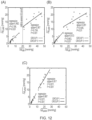
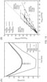
- Figure 13 illustrates the overestimation obtained with the sB formulation (regression slope of 0.496) and with the sAW formulation applied to 1D velocity profiles obtained from an idealized color Doppler acquisition (regression slope of 0.755 when comparing against averaging results from 12 velocity profiles in each case). Variability is introduced by the specific choice of the profile, determined by the insonation plane. A higher correlation is achieved with an idealized color Doppler 3D acquisition using the sAW formulation (regression slope of 1.076).
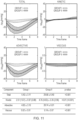
- the TPD is driven by the forces that spatially accelerate the flow ejected by the ventricle through a narrow orifice regardless of the other two components of the pressure drops, as illustrated in Figure 11 .
- the transport of momentum i.e. the advective forces
- the transport of momentum is the principal contributor to the TPD, with a secondary role played by temporal accelerations (or kinetic drops), and minor impact of viscous dissipative stresses.
- Equation A.4 by replacing the surface integrals at the outlet plane for line integrals along the line ⁇ defined by intersecting the hypothetical insonation plane with the outlet plane of the aortic lumen plane, and by considering the fact that velocity values are already projected in the direction of the line of insonation, can be rearranged as,
- blood density ⁇ 1060 kg / m 3
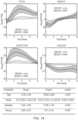
- Figure 14 and Figure 15 show the temporal transients of the averaged pressure drop components (total, kinetic, advective and viscous) during systole for the two groups of patients respectively obtained in the AAR and DAR defined above.
- Tabulated results report how the widening of the aortic flow jet downstream of the VC captured in the AAR causes a recovery of the total TPD in Group II subjects, with drop magnitudes comparable with that observed in the TVR (see Figure 11 ) but with opposite sign (absolute peak means of 11.74 mmHg in AAR and 31.84mmHg in TVR).
- Velocity profiles are generally blunt, with v MAX ⁇ 2.5 m / s , for subjects in Group I, clearly showing lower variability of the velocity profiles when compared to subjects in Group II, where peak velocities are v MAX ⁇ 2.5 m / s .
- the velocity profile is highly non-axisymmetric for Group II patients, therefore motivating the larger variability obtained in this group.
- the first embodiment relates to performing only a subset of the WERP processing, by considering only the advective term of the full WERP equation. As such, less information is required, and simpler imaging systems may be used, particularly 2D PC MRI systems, and 3D Doppler ECG systems.
- Figure 9 is a block diagram of a 2D MRI system that may be used to perform the processing to calculate the pressure drop.
- a 2D phase contrast magnetic resonance imaging (2D PC MRI) system 902 comprising MR imaging coils within which the subject is located, controlled by an MRI imaging control system 98, including an MRI controller processor 90.
- the MRI imaging control system 98 including the MRI controller processor 90 function in a conventional manner to allow 3 dimensional phase contrast magnetic resonance image data to be obtained, for example of an internal blood vessel of the subject the pressure difference across it is desired to know.
- TPD transvalvular pressure drops
- other blood vessels may also be monitored, as desired.
- the 2D PC MRI system 98, 902 collects 2D PC MRI data 92 of the imaging subject, which is saved for further processing and analysis.
- the 2D PC MRI system 98, 902 also includes a complete advective WERP computation program 94, which acts to process the 2D PC MRI data 92 as described above in accordance with the complete advective WERP processing method described, to obtain WERP pressure estimation data 96.
- the complete advective WERP processing method is a simplification of the WERP equation by only taking one of the three additive terms of energy, the advective term.
- the resulting pressure estimation data 96 gives an estimate of pressure at the measured inlet and outlet planes, but neglects the effects of the vessel walls between the inlet and outlet. As such, it does not provide a complete solution for every point within the vessel between the inlet and outlet, but instead provides solutions for the inlet and outlet only, but from which pressure drop across the vessel can then be found.
- FIG. 10(A) illustrates the 3D Doppler ultrasound ECG equivalent system.
- a transducer 1000 obtained 3D Doppler measurements from the subject, under the control of 3D Doppler ECG system 102, comprising 3D Doppler ECG controller 104.
- the system produces 3D Doppler ECG data 106, and which is then used as an input to the cAW calculation program 108, which performs the necessary processing as described previously to find solutions for the inlet and outlet planes of the vessel being monitored, which is then stored and output as cAW output data 110.
- Figure 7 illustrates the basic method of operation of the cAW approach.
- the MRI data or ECG data of the inlet and outlet planes of the subject vessel for which pressure drop across is to be found is obtained.
- the complete advective WERP values for the inlet and outlet planes are found, for example using the processing represented by equation A.3 above (s.7.4).
- the complete advective WERP data is stored and/or output to a user, for example on a display screen (s.7.6).
- the second embodiment relates to the simplifed advective WERP approach, which can be performed using 2D Doppler ECG data, although of course it may also be applied with other imaging systems that obtain more information, such as 2D PC MRI, 3D Doppler ECG.
- Figure 10(B) shows a 2D Doppler ultrasound ECG equivalent system.
- a transducer 1000 obtains 2D Doppler measurements from the subject, under the control of 2D Doppler ECG system 152, comprising 2D Doppler ECG controller 154.
- the system produces 2D Doppler ECG data 156, and which is then used as an input to the sAW calculation program 158, which performs the necessary processing as described previously to find solutions for the outlet planes of the vessel being monitored, which is then stored and output as sAW output data 160.
- Figure 8 illustrates the basic method of operation of the sAW approach.
- the ECG data of the outlet plane of the subject vessel for which pressure drop across is to be found is obtained.
- the simplified advective WERP values for the inlet or outlet planes are found, for example using the processing represented by equation A.5 above (s.8.4).
- the simplified advective WERP data is stored and/or output to a user, for example on a display screen (s.8.6).
- FIG 11 shows the TPD estimated from 4D PC-MRI data using the WERP formulation.
- Top panel average temporal transients of the TPD during systole of the total (top left), kinetic (top right), advective (bottom left) and viscous (bottom right) components on Group I (light grey filled area) and Group II (dark grey filled area) subjects.
- Bottom panel distribution (mean ⁇ standard deviation) for peak TPD ⁇ p MAX ( mmHg ), including the significance of differences between Group I and Group II (unpaired T-test). Peak values of the kinetic pressure drops are reported on acceleration and deceleration (into brackets, negative peaks) systolic events separately. It must be noted that the pressure components do not add up to the total TPD, as the peak kinetic, advective and viscous drops do not happen simultaneously.
- FIG. 13 shows the results of computation of WERP advective drops based on 4D PC-MRI and idealized echocardiographic data.
- Systolic advective TPD transients computed from 4D PCMRI (black solid line), color Doppler 3D (grey solid line) using the sAW formulation, color Doppler 2D using the sAW formulation to 1D profiles obtained at the peak systolic frame (grey circles), and continuous Doppler 1D using the sB formulation (grey dashed line).
- Figure 14 illustrates pressure drops in the AAR estimated from 4D PC-MRI data using the WERP formulation.
- Top panel average temporal transients of the pressure drops during systole, with total (top left), kinetic (top right), advective (bottom left) and viscous (bottom right) components on Group I (light grey filled area) and Group II (dark grey filled area) subjects.
- Bottom panel distribution (mean ⁇ standard deviation) for peak drops ⁇ p MAX ( mmHg ) including the significance of differences between Group I and Group II (unpaired T-test). Peak values of the kinetic pressure drops are reported on acceleration and deceleration (into brackets, negative peaks) systolic events separately.
- Figure 15 shows pressure drops in the DAR estimated from 4D PC-MRI data using the WERP formulation.
- Top panel average temporal transients of the drops during systole, with total (top left), kinetic (top right), advective (bottom left) and viscous (bottom right) components on Group I (light grey filled area) and Group II (dark grey filled area) subjects.
- Bottom panel distribution (mean ⁇ standard deviation) for peak drops ⁇ p MAX ( mmHg ) , including the significance of differences between Group I and Group II (unpaired T-test). Peak values of the total and kinetic pressure drops are reported on acceleration and deceleration (into brackets) systolic events separately.
- Figure 16 shows the results of an in silico test on a 3D straight pipe with steady velocity field.
- Top panel representation of velocity profiles at inlet/outlet planes obtained with different velocity shape coefficients.
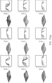
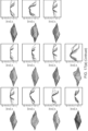
- Figure 17 shows 2D velocity profiles from mimicked 2D color Doppler echocardiographic images at the outlet plane for Group I ( Figure 17A ) and Group II ( Figure 17B ).
Landscapes
- Health & Medical Sciences (AREA)
- Life Sciences & Earth Sciences (AREA)
- Engineering & Computer Science (AREA)
- Physics & Mathematics (AREA)
- Molecular Biology (AREA)
- General Health & Medical Sciences (AREA)
- Biophysics (AREA)
- Pathology (AREA)
- Veterinary Medicine (AREA)
- Biomedical Technology (AREA)
- Heart & Thoracic Surgery (AREA)
- Medical Informatics (AREA)
- Public Health (AREA)
- Surgery (AREA)
- Animal Behavior & Ethology (AREA)
- Nuclear Medicine, Radiotherapy & Molecular Imaging (AREA)
- Physiology (AREA)
- Radiology & Medical Imaging (AREA)
- Cardiology (AREA)
- Hematology (AREA)
- Computer Vision & Pattern Recognition (AREA)
- High Energy & Nuclear Physics (AREA)
- Vascular Medicine (AREA)
- Artificial Intelligence (AREA)
- Psychiatry (AREA)
- Signal Processing (AREA)
- Magnetic Resonance Imaging Apparatus (AREA)
Claims (7)
- Computerimplementiertes Verfahren zum Bestimmen einer Advektionsdruckdifferenz über einem Blutgefäß, die aus einem Blutstrom innerhalb des Blutgefäßes entsteht, umfassend:Ermitteln von Blutgeschwindigkeitsdaten an den Einlass- und Auslassebenen des Blutgefäßes; undVerarbeiten der Blutgeschwindigkeitsdaten, um Folgendes zu bestimmen:i) eine Strömungsrate (Q) des Blutes durch das Blutgefäß; undii) eine Advektionsenergierate (A) des Blutstroms durch das Blutgefäß; dadurch gekennzeichnet, dass das Verfahren ferner umfasst:Berechnen der Druckdifferenz in Abhängigkeit von sowohl der Strömungsrate (Q) als auch der Advektionsenergierate (A) ohne Berücksichtigung einer Rate einer viskosen Dissipation (V) und einer kinetischen Energie (K) des Blutstroms durch das Blutgefäß, undwobei die Blutgeschwindigkeitsdaten nicht von einem anderen Ort in dem Blutgefäß als den Einlass- und Auslassebenen ermittelt werden.
- Verfahren nach Anspruch 1, wobei:i) die Strömungsrate Q von einem Oberflächenintegral der Blutgeschwindigkeitsdaten über entweder der Einlass- oder der Auslassebene des Blutgefäßes oder über irgendeiner anderen Ebene, die das Rohr in zwei Unterabschnitte teilt, abhängt; und/oderii) die Advektionsenergierate A von einer Summe der Oberflächenintegrale der zeitabhängigen Blutgeschwindigkeitsdaten oder davon abgeleiteter Daten über den Einlass- und Auslassebenen und von der Blutdichte abhängt.
- Verfahren nach Anspruch 1 oder 2, wobei

 a)
a) b)
b)
- Computerimplementiertes Verfahren zum Bestimmen einer Advektionsdruckdifferenz über einem Blutgefäß, die aus einem Blutstrom innerhalb des Blutgefäßes entsteht, wobei das Blutgefäß ein vaskuläres Segment definiert, bei dem Blutgeschwindigkeiten an einer Einlassebene des Blutgefäßes im Vergleich zu Blutgeschwindigkeiten an einer Auslassebene des Blutgefäßes vernachlässigbar sind, dadurch gekennzeichnet, dass das Verfahren umfasst:Ermitteln von partiellen Blutgeschwindigkeitsdaten von dem Auslass des Blutgefäßes, wobei die partiellen Blutgeschwindigkeitsdaten entlang einer Linie an der Auslassebene des Blutgefäßes ermittelt werden, wobei die Linie durch Schneiden einer Bildebene mit der Auslassebene des Blutgefäßes definiert wird;Schätzen eines vollständigen Geschwindigkeitsprofils anhand der partiellen Daten; undBerechnen der Druckdifferenz in Abhängigkeit von dem geschätzten vollständigen Geschwindigkeitsprofil und einer bekannten Blutdichte,wobei die Erfassung der partiellen Blutgeschwindigkeitsdaten entlang der Linie direkt als beste Schätzung des vollständigen Geschwindigkeitsprofils genommen wird, wobei die Druckdifferenz gegeben ist durch:
 wobei v die Blutgeschwindigkeit entlang der Linie λ ist und rho die Fluiddichte ist.
 - Verfahren nach Anspruch 4, wobei die partiellen Blutgeschwindigkeitsdaten kein 3D-Vektor sind, sondern eine Projektion dieses Vektors in einer Richtung nahe der Strömungsrichtung sind.
- Verfahren nach einem der vorangehenden Ansprüche, wobei:A) in Abhängigkeit von einem der Ansprüche 1 bis 3 die Blutgeschwindigkeitsdaten erhalten werden von:i) 4D-Phasen-Kontrast-Magnetresonanzbildgebungsdaten; und/oderii) 2D-Phasen-Kontrast-Magnetresonanzbildgebungsdaten; und/oderiii) Doppler-Echokardiographiedaten; und/oderiv) Ultrafast-Echokardiographiedaten; oderB) in Abhängigkeit von einem der Ansprüche 4 bis 5 die Blutgeschwindigkeitsdaten erhalten werden durchi) 2D-Doppler-Echokardiographie; und/oderii) Ultrafast-2D-Echokardiographie.
- Verfahren nach einem der Ansprüche 1 bis 6, wobei der Blutstrom ein In-vivo-Blutstrom ist.
Applications Claiming Priority (2)
| Application Number | Priority Date | Filing Date | Title |
|---|---|---|---|
| GBGB1604412.5A GB201604412D0 (en) | 2016-03-15 | 2016-03-15 | Method and system pressure drop estimation |
| PCT/GB2017/050694 WO2017158343A1 (en) | 2016-03-15 | 2017-03-14 | Method and system for pressure drop estimation |
Publications (2)
| Publication Number | Publication Date |
|---|---|
| EP3429470A1 EP3429470A1 (de) | 2019-01-23 |
| EP3429470B1 true EP3429470B1 (de) | 2024-11-06 |
Family
ID=55952357
Family Applications (1)
| Application Number | Title | Priority Date | Filing Date |
|---|---|---|---|
| EP17713378.2A Active EP3429470B1 (de) | 2016-03-15 | 2017-03-14 | Verfahren zur kalkulation von druckabfall |
Country Status (5)
| Country | Link |
|---|---|
| US (1) | US11701008B2 (de) |
| EP (1) | EP3429470B1 (de) |
| CN (1) | CN109219392A (de) |
| GB (1) | GB201604412D0 (de) |
| WO (1) | WO2017158343A1 (de) |
Families Citing this family (5)
| Publication number | Priority date | Publication date | Assignee | Title |
|---|---|---|---|---|
| GB201604412D0 (en) | 2016-03-15 | 2016-04-27 | King S College London | Method and system pressure drop estimation |
| US11154205B2 (en) | 2016-03-15 | 2021-10-26 | King's College London | Method and system for pressure drop estimation |
| US20220110530A2 (en) * | 2019-12-09 | 2022-04-14 | Nordsletten David | Method and System for Estimating Pressure Difference in Turbulent Flow |
| CN112971818B (zh) * | 2021-01-28 | 2022-10-04 | 杭州脉流科技有限公司 | 微循环阻力指数的获取方法、装置、计算机设备和存储介质 |
| CN116188336B (zh) * | 2023-04-17 | 2023-12-22 | 柏意慧心(杭州)网络科技有限公司 | 基于血管造影的心肌病形态学计算方法、装置及存储介质 |
Family Cites Families (12)
| Publication number | Priority date | Publication date | Assignee | Title |
|---|---|---|---|---|
| DE19738870A1 (de) * | 1997-09-05 | 1999-03-18 | Bayer Ag | Verfahren und Vorrichtung zur kontinuierlichen Vermischung einer Tröpfchendispersion mit einer Flüssigkeit |
| US6059490A (en) * | 1998-05-05 | 2000-05-09 | Kauppi; Frederick J. | Hydraulic energy dissipating offset stepped spillway and methods of constructing and using the same |
| US20020049403A1 (en) * | 2000-10-03 | 2002-04-25 | Audencio Alanis | Method and apparatus for permanent vascular access for hemodialysis |
| GB2479340A (en) | 2010-03-10 | 2011-10-12 | Imp Innovations Ltd | Method and apparatus for the measurement of a fluid flow restriction in a vessel |
| CN102289790B (zh) * | 2011-06-22 | 2012-12-19 | 哈尔滨工业大学 | 一种超声心动图粒子图像测速速度场修正方法 |
| US8696584B2 (en) * | 2011-10-05 | 2014-04-15 | 3Dt Holdings, Llc | Devices, systems and methods for determining fractional flow reserve in the presence of a catheter |
| US10034614B2 (en) * | 2012-02-29 | 2018-07-31 | General Electric Company | Fractional flow reserve estimation |
| US9135699B2 (en) | 2012-03-15 | 2015-09-15 | Siemens Aktiengesellschaft | Method and system for hemodynamic assessment of aortic coarctation from medical image data |
| US9462954B2 (en) * | 2013-09-04 | 2016-10-11 | Siemens Aktiengesellschaft | Method and system for blood flow velocity reconstruction from medical images |
| NL2012459B1 (en) | 2014-03-18 | 2016-01-08 | Medis Ass B V | Method and device for determining deviation in pressure in a blood vessel. |
| US10299862B2 (en) | 2015-02-05 | 2019-05-28 | Siemens Healthcare Gmbh | Three-dimensional quantitative heart hemodynamics in medical imaging |
| GB201604412D0 (en) | 2016-03-15 | 2016-04-27 | King S College London | Method and system pressure drop estimation |
-
2016
- 2016-03-15 GB GBGB1604412.5A patent/GB201604412D0/en not_active Ceased
-
2017
- 2017-03-14 CN CN201780029898.7A patent/CN109219392A/zh active Pending
- 2017-03-14 WO PCT/GB2017/050694 patent/WO2017158343A1/en not_active Ceased
- 2017-03-14 EP EP17713378.2A patent/EP3429470B1/de active Active
-
2021
- 2021-09-21 US US17/480,313 patent/US11701008B2/en active Active
Also Published As
| Publication number | Publication date |
|---|---|
| EP3429470A1 (de) | 2019-01-23 |
| WO2017158343A1 (en) | 2017-09-21 |
| US11701008B2 (en) | 2023-07-18 |
| GB201604412D0 (en) | 2016-04-27 |
| CN109219392A (zh) | 2019-01-15 |
| US20220000372A1 (en) | 2022-01-06 |
Similar Documents
| Publication | Publication Date | Title |
|---|---|---|
| Garcia et al. | The role of imaging of flow patterns by 4D flow MRI in aortic stenosis | |
| Prakasa et al. | Feasibility and variability of three dimensional echocardiography in arrhythmogenic right ventricular dysplasia/cardiomyopathy | |
| Donati et al. | Non-invasive pressure difference estimation from PC-MRI using the work-energy equation | |
| US11701008B2 (en) | Pressure drop estimation | |
| US10271905B2 (en) | Patient-specific virtual intervention laboratory to prevent stroke | |
| Dewey et al. | Evaluation of global and regional left ventricular function with 16-slice computed tomography, biplane cineventriculography, and two-dimensional transthoracic echocardiography: comparison with magnetic resonance imaging | |
| Ioannidis et al. | Electrocardiogram-gated single-photonemission computed tomography versus cardiacmagnetic resonance imaging for the assessmentof left ventricular volumes and ejection fraction: A meta-analysis | |
| Gaspar et al. | Three-dimensional imaging of the left ventricular outflow tract: impact on aortic valve area estimation by the continuity equation | |
| Harloff et al. | Determination of aortic stiffness using 4D flow cardiovascular magnetic resonance-a population-based study | |
| Nichols et al. | Automation of gated tomographic left ventricular ejection fraction | |
| Mynard et al. | Errors in the estimation of wall shear stress by maximum Doppler velocity | |
| KR101939778B1 (ko) | 필요 혈류량 결정 방법 및 장치, 혈류 영상 생성 방법 및 장치, 심근 관류 영상 처리 방법 및 장치 | |
| Zhao et al. | Quantification of myocardial delayed enhancement and wall thickness in hypertrophic cardiomyopathy: multidetector computed tomography versus magnetic resonance imaging | |
| US20130289408A1 (en) | Ultrasound image capture device, ultrasound image capture method, ultrasound image capture program | |
| US20140088414A1 (en) | Method for Estimating Flow Rates, Pressure Gradients, Coronary Flow Reserve, and Fractional Flow Reserve from Patient Specific Computed Tomography Angiogram-Based Contrast Distribution Data | |
| US10134127B2 (en) | Method for post-processing flow-sensitive phase contrast magnetic resonance images | |
| Nosir et al. | Measurements and day-to-day variabilities of left ventricular volumes and ejection fraction by three-dimensional echocardiography and comparison with magnetic resonance imaging | |
| Nichols et al. | Comparison between ECTb and QGS for assessment of left ventricular function from gated myocardial perfusion SPECT | |
| JP2015512292A (ja) | マルチプルイメージデータループを獲得して分析する方法及びシステム | |
| Dietenbeck et al. | 3D aortic morphology and stiffness in MRI using semi-automated cylindrical active surface provides optimized description of the vascular effects of aging and hypertension | |
| US11154205B2 (en) | Method and system for pressure drop estimation | |
| Lu et al. | Reformatted four-chamber and short-axis views of the heart using thin section (≤ 2 mm) MDCT images | |
| Nichols et al. | Feasibility of detecting cardiac torsion in myocardial perfusion gated SPECT data | |
| Chandra et al. | Novel techniques for assessment of left ventricular systolic function | |
| Koka et al. | Left atrial volume: comparison of 2D and 3D transthoracic echocardiography with ECG-gated CT angiography |
Legal Events
| Date | Code | Title | Description |
|---|---|---|---|
| STAA | Information on the status of an ep patent application or granted ep patent |
Free format text: STATUS: UNKNOWN |
|
| STAA | Information on the status of an ep patent application or granted ep patent |
Free format text: STATUS: THE INTERNATIONAL PUBLICATION HAS BEEN MADE |
|
| PUAI | Public reference made under article 153(3) epc to a published international application that has entered the european phase |
Free format text: ORIGINAL CODE: 0009012 |
|
| STAA | Information on the status of an ep patent application or granted ep patent |
Free format text: STATUS: REQUEST FOR EXAMINATION WAS MADE |
|
| 17P | Request for examination filed |
Effective date: 20180905 |
|
| AK | Designated contracting states |
Kind code of ref document: A1 Designated state(s): AL AT BE BG CH CY CZ DE DK EE ES FI FR GB GR HR HU IE IS IT LI LT LU LV MC MK MT NL NO PL PT RO RS SE SI SK SM TR |
|
| AX | Request for extension of the european patent |
Extension state: BA ME |
|
| DAV | Request for validation of the european patent (deleted) | ||
| DAX | Request for extension of the european patent (deleted) | ||
| STAA | Information on the status of an ep patent application or granted ep patent |
Free format text: STATUS: EXAMINATION IS IN PROGRESS |
|
| 17Q | First examination report despatched |
Effective date: 20220421 |
|
| RAP3 | Party data changed (applicant data changed or rights of an application transferred) |
Owner name: KING'S COLLEGE LONDON |
|
| REG | Reference to a national code |
Ref country code: DE Ref legal event code: R079 Free format text: PREVIOUS MAIN CLASS: A61B0005055000 Ipc: A61B0005026000 Ref country code: DE Ref legal event code: R079 Ref document number: 602017085912 Country of ref document: DE Free format text: PREVIOUS MAIN CLASS: A61B0005055000 Ipc: A61B0005026000 |
|
| GRAP | Despatch of communication of intention to grant a patent |
Free format text: ORIGINAL CODE: EPIDOSNIGR1 |
|
| STAA | Information on the status of an ep patent application or granted ep patent |
Free format text: STATUS: GRANT OF PATENT IS INTENDED |
|
| RIC1 | Information provided on ipc code assigned before grant |
Ipc: A61B 5/00 20060101ALN20240522BHEP Ipc: G16H 30/40 20180101ALN20240522BHEP Ipc: A61B 8/08 20060101ALN20240522BHEP Ipc: A61B 8/06 20060101ALN20240522BHEP Ipc: A61B 5/055 20060101ALI20240522BHEP Ipc: A61B 5/021 20060101ALI20240522BHEP Ipc: A61B 5/026 20060101AFI20240522BHEP |
|
| INTG | Intention to grant announced |
Effective date: 20240612 |
|
| GRAS | Grant fee paid |
Free format text: ORIGINAL CODE: EPIDOSNIGR3 |
|
| GRAA | (expected) grant |
Free format text: ORIGINAL CODE: 0009210 |
|
| STAA | Information on the status of an ep patent application or granted ep patent |
Free format text: STATUS: THE PATENT HAS BEEN GRANTED |
|
| AK | Designated contracting states |
Kind code of ref document: B1 Designated state(s): AL AT BE BG CH CY CZ DE DK EE ES FI FR GB GR HR HU IE IS IT LI LT LU LV MC MK MT NL NO PL PT RO RS SE SI SK SM TR |
|
| REG | Reference to a national code |
Ref country code: GB Ref legal event code: FG4D |
|
| P01 | Opt-out of the competence of the unified patent court (upc) registered |
Free format text: CASE NUMBER: APP_54542/2024 Effective date: 20241003 |
|
| REG | Reference to a national code |
Ref country code: CH Ref legal event code: EP |
|
| REG | Reference to a national code |
Ref country code: DE Ref legal event code: R096 Ref document number: 602017085912 Country of ref document: DE |
|
| REG | Reference to a national code |
Ref country code: IE Ref legal event code: FG4D |
|
| REG | Reference to a national code |
Ref country code: LT Ref legal event code: MG9D |
|
| REG | Reference to a national code |
Ref country code: NL Ref legal event code: MP Effective date: 20241106 |
|
| PG25 | Lapsed in a contracting state [announced via postgrant information from national office to epo] |
Ref country code: HR Free format text: LAPSE BECAUSE OF FAILURE TO SUBMIT A TRANSLATION OF THE DESCRIPTION OR TO PAY THE FEE WITHIN THE PRESCRIBED TIME-LIMIT Effective date: 20241106 Ref country code: IS Free format text: LAPSE BECAUSE OF FAILURE TO SUBMIT A TRANSLATION OF THE DESCRIPTION OR TO PAY THE FEE WITHIN THE PRESCRIBED TIME-LIMIT Effective date: 20250306 Ref country code: PT Free format text: LAPSE BECAUSE OF FAILURE TO SUBMIT A TRANSLATION OF THE DESCRIPTION OR TO PAY THE FEE WITHIN THE PRESCRIBED TIME-LIMIT Effective date: 20250306 |
|
| PG25 | Lapsed in a contracting state [announced via postgrant information from national office to epo] |
Ref country code: NL Free format text: LAPSE BECAUSE OF FAILURE TO SUBMIT A TRANSLATION OF THE DESCRIPTION OR TO PAY THE FEE WITHIN THE PRESCRIBED TIME-LIMIT Effective date: 20241106 Ref country code: FI Free format text: LAPSE BECAUSE OF FAILURE TO SUBMIT A TRANSLATION OF THE DESCRIPTION OR TO PAY THE FEE WITHIN THE PRESCRIBED TIME-LIMIT Effective date: 20241106 |
|
| REG | Reference to a national code |
Ref country code: AT Ref legal event code: MK05 Ref document number: 1738450 Country of ref document: AT Kind code of ref document: T Effective date: 20241106 |
|
| PG25 | Lapsed in a contracting state [announced via postgrant information from national office to epo] |
Ref country code: BG Free format text: LAPSE BECAUSE OF FAILURE TO SUBMIT A TRANSLATION OF THE DESCRIPTION OR TO PAY THE FEE WITHIN THE PRESCRIBED TIME-LIMIT Effective date: 20241106 |
|
| PG25 | Lapsed in a contracting state [announced via postgrant information from national office to epo] |
Ref country code: ES Free format text: LAPSE BECAUSE OF FAILURE TO SUBMIT A TRANSLATION OF THE DESCRIPTION OR TO PAY THE FEE WITHIN THE PRESCRIBED TIME-LIMIT Effective date: 20241106 |
|
| PG25 | Lapsed in a contracting state [announced via postgrant information from national office to epo] |
Ref country code: NO Free format text: LAPSE BECAUSE OF FAILURE TO SUBMIT A TRANSLATION OF THE DESCRIPTION OR TO PAY THE FEE WITHIN THE PRESCRIBED TIME-LIMIT Effective date: 20250206 |
|
| PG25 | Lapsed in a contracting state [announced via postgrant information from national office to epo] |
Ref country code: AT Free format text: LAPSE BECAUSE OF FAILURE TO SUBMIT A TRANSLATION OF THE DESCRIPTION OR TO PAY THE FEE WITHIN THE PRESCRIBED TIME-LIMIT Effective date: 20241106 Ref country code: LV Free format text: LAPSE BECAUSE OF FAILURE TO SUBMIT A TRANSLATION OF THE DESCRIPTION OR TO PAY THE FEE WITHIN THE PRESCRIBED TIME-LIMIT Effective date: 20241106 Ref country code: GR Free format text: LAPSE BECAUSE OF FAILURE TO SUBMIT A TRANSLATION OF THE DESCRIPTION OR TO PAY THE FEE WITHIN THE PRESCRIBED TIME-LIMIT Effective date: 20250207 |
|
| PG25 | Lapsed in a contracting state [announced via postgrant information from national office to epo] |
Ref country code: PL Free format text: LAPSE BECAUSE OF FAILURE TO SUBMIT A TRANSLATION OF THE DESCRIPTION OR TO PAY THE FEE WITHIN THE PRESCRIBED TIME-LIMIT Effective date: 20241106 |
|
| PG25 | Lapsed in a contracting state [announced via postgrant information from national office to epo] |
Ref country code: RS Free format text: LAPSE BECAUSE OF FAILURE TO SUBMIT A TRANSLATION OF THE DESCRIPTION OR TO PAY THE FEE WITHIN THE PRESCRIBED TIME-LIMIT Effective date: 20250206 |
|
| PG25 | Lapsed in a contracting state [announced via postgrant information from national office to epo] |
Ref country code: SM Free format text: LAPSE BECAUSE OF FAILURE TO SUBMIT A TRANSLATION OF THE DESCRIPTION OR TO PAY THE FEE WITHIN THE PRESCRIBED TIME-LIMIT Effective date: 20241106 |
|
| PG25 | Lapsed in a contracting state [announced via postgrant information from national office to epo] |
Ref country code: DK Free format text: LAPSE BECAUSE OF FAILURE TO SUBMIT A TRANSLATION OF THE DESCRIPTION OR TO PAY THE FEE WITHIN THE PRESCRIBED TIME-LIMIT Effective date: 20241106 |
|
| PG25 | Lapsed in a contracting state [announced via postgrant information from national office to epo] |
Ref country code: EE Free format text: LAPSE BECAUSE OF FAILURE TO SUBMIT A TRANSLATION OF THE DESCRIPTION OR TO PAY THE FEE WITHIN THE PRESCRIBED TIME-LIMIT Effective date: 20241106 |
|
| PG25 | Lapsed in a contracting state [announced via postgrant information from national office to epo] |
Ref country code: RO Free format text: LAPSE BECAUSE OF FAILURE TO SUBMIT A TRANSLATION OF THE DESCRIPTION OR TO PAY THE FEE WITHIN THE PRESCRIBED TIME-LIMIT Effective date: 20241106 |
|
| PG25 | Lapsed in a contracting state [announced via postgrant information from national office to epo] |
Ref country code: SK Free format text: LAPSE BECAUSE OF FAILURE TO SUBMIT A TRANSLATION OF THE DESCRIPTION OR TO PAY THE FEE WITHIN THE PRESCRIBED TIME-LIMIT Effective date: 20241106 |
|
| PG25 | Lapsed in a contracting state [announced via postgrant information from national office to epo] |
Ref country code: CZ Free format text: LAPSE BECAUSE OF FAILURE TO SUBMIT A TRANSLATION OF THE DESCRIPTION OR TO PAY THE FEE WITHIN THE PRESCRIBED TIME-LIMIT Effective date: 20241106 |
|
| PG25 | Lapsed in a contracting state [announced via postgrant information from national office to epo] |
Ref country code: IT Free format text: LAPSE BECAUSE OF FAILURE TO SUBMIT A TRANSLATION OF THE DESCRIPTION OR TO PAY THE FEE WITHIN THE PRESCRIBED TIME-LIMIT Effective date: 20241106 |
|
| REG | Reference to a national code |
Ref country code: DE Ref legal event code: R097 Ref document number: 602017085912 Country of ref document: DE |
|
| PG25 | Lapsed in a contracting state [announced via postgrant information from national office to epo] |
Ref country code: SE Free format text: LAPSE BECAUSE OF FAILURE TO SUBMIT A TRANSLATION OF THE DESCRIPTION OR TO PAY THE FEE WITHIN THE PRESCRIBED TIME-LIMIT Effective date: 20241106 |
|
| PLBE | No opposition filed within time limit |
Free format text: ORIGINAL CODE: 0009261 |
|
| STAA | Information on the status of an ep patent application or granted ep patent |
Free format text: STATUS: NO OPPOSITION FILED WITHIN TIME LIMIT |
|
| PG25 | Lapsed in a contracting state [announced via postgrant information from national office to epo] |
Ref country code: MC Free format text: LAPSE BECAUSE OF FAILURE TO SUBMIT A TRANSLATION OF THE DESCRIPTION OR TO PAY THE FEE WITHIN THE PRESCRIBED TIME-LIMIT Effective date: 20241106 |
|
| 26N | No opposition filed |
Effective date: 20250807 |
|
| REG | Reference to a national code |
Ref country code: CH Ref legal event code: H13 Free format text: ST27 STATUS EVENT CODE: U-0-0-H10-H13 (AS PROVIDED BY THE NATIONAL OFFICE) Effective date: 20251024 |
|
| PG25 | Lapsed in a contracting state [announced via postgrant information from national office to epo] |
Ref country code: LU Free format text: LAPSE BECAUSE OF NON-PAYMENT OF DUE FEES Effective date: 20250314 |
|
| REG | Reference to a national code |
Ref country code: BE Ref legal event code: MM Effective date: 20250331 |
|
| PG25 | Lapsed in a contracting state [announced via postgrant information from national office to epo] |
Ref country code: BE Free format text: LAPSE BECAUSE OF NON-PAYMENT OF DUE FEES Effective date: 20250331 |
|
| PG25 | Lapsed in a contracting state [announced via postgrant information from national office to epo] |
Ref country code: CH Free format text: LAPSE BECAUSE OF NON-PAYMENT OF DUE FEES Effective date: 20250331 |
|
| PG25 | Lapsed in a contracting state [announced via postgrant information from national office to epo] |
Ref country code: IE Free format text: LAPSE BECAUSE OF NON-PAYMENT OF DUE FEES Effective date: 20250314 |
|
| PGFP | Annual fee paid to national office [announced via postgrant information from national office to epo] |
Ref country code: GB Payment date: 20260306 Year of fee payment: 10 |
|
| PGFP | Annual fee paid to national office [announced via postgrant information from national office to epo] |
Ref country code: DE Payment date: 20260320 Year of fee payment: 10 |
|
| PGFP | Annual fee paid to national office [announced via postgrant information from national office to epo] |
Ref country code: FR Payment date: 20260325 Year of fee payment: 10 |