EP3429025A1 - A cable, method of making thereof and corresponding apparatus - Google Patents
A cable, method of making thereof and corresponding apparatus Download PDFInfo
- Publication number
- EP3429025A1 EP3429025A1 EP17181483.3A EP17181483A EP3429025A1 EP 3429025 A1 EP3429025 A1 EP 3429025A1 EP 17181483 A EP17181483 A EP 17181483A EP 3429025 A1 EP3429025 A1 EP 3429025A1
- Authority
- EP
- European Patent Office
- Prior art keywords
- cable
- polymer core
- radiative
- cables
- cladding material
- Prior art date
- Legal status (The legal status is an assumption and is not a legal conclusion. Google has not performed a legal analysis and makes no representation as to the accuracy of the status listed.)
- Withdrawn
Links
- 238000004519 manufacturing process Methods 0.000 title description 2
- 229920000642 polymer Polymers 0.000 claims abstract description 75
- 239000000463 material Substances 0.000 claims abstract description 53
- 238000005253 cladding Methods 0.000 claims abstract description 50
- 239000003989 dielectric material Substances 0.000 claims abstract description 7
- 238000000034 method Methods 0.000 claims description 8
- 239000002184 metal Substances 0.000 claims description 7
- 229910052751 metal Inorganic materials 0.000 claims description 7
- 230000008878 coupling Effects 0.000 description 9
- 238000010168 coupling process Methods 0.000 description 9
- 238000005859 coupling reaction Methods 0.000 description 9
- RYGMFSIKBFXOCR-UHFFFAOYSA-N Copper Chemical compound [Cu] RYGMFSIKBFXOCR-UHFFFAOYSA-N 0.000 description 3
- 238000004891 communication Methods 0.000 description 3
- 229910052802 copper Inorganic materials 0.000 description 3
- 239000010949 copper Substances 0.000 description 3
- 239000007787 solid Substances 0.000 description 3
- 230000009286 beneficial effect Effects 0.000 description 2
- 238000001514 detection method Methods 0.000 description 2
- 238000010348 incorporation Methods 0.000 description 2
- 238000012986 modification Methods 0.000 description 2
- 230000004048 modification Effects 0.000 description 2
- 230000003044 adaptive effect Effects 0.000 description 1
- 238000003491 array Methods 0.000 description 1
- 238000000151 deposition Methods 0.000 description 1
- 230000005611 electricity Effects 0.000 description 1
- 239000006260 foam Substances 0.000 description 1
- 239000006261 foam material Substances 0.000 description 1
- 239000011796 hollow space material Substances 0.000 description 1
- 230000000116 mitigating effect Effects 0.000 description 1
- 238000012544 monitoring process Methods 0.000 description 1
- 239000002861 polymer material Substances 0.000 description 1
- 230000005855 radiation Effects 0.000 description 1
- 230000035945 sensitivity Effects 0.000 description 1
- 229910052709 silver Inorganic materials 0.000 description 1
- 239000004332 silver Substances 0.000 description 1
Images


Classifications
-
- H—ELECTRICITY
- H01—ELECTRIC ELEMENTS
- H01P—WAVEGUIDES; RESONATORS, LINES, OR OTHER DEVICES OF THE WAVEGUIDE TYPE
- H01P3/00—Waveguides; Transmission lines of the waveguide type
- H01P3/12—Hollow waveguides
- H01P3/122—Dielectric loaded (not air)
-
- H—ELECTRICITY
- H01—ELECTRIC ELEMENTS
- H01P—WAVEGUIDES; RESONATORS, LINES, OR OTHER DEVICES OF THE WAVEGUIDE TYPE
- H01P3/00—Waveguides; Transmission lines of the waveguide type
- H01P3/16—Dielectric waveguides, i.e. without a longitudinal conductor
-
- H—ELECTRICITY
- H01—ELECTRIC ELEMENTS
- H01Q—ANTENNAS, i.e. RADIO AERIALS
- H01Q13/00—Waveguide horns or mouths; Slot antennas; Leaky-waveguide antennas; Equivalent structures causing radiation along the transmission path of a guided wave
- H01Q13/20—Non-resonant leaky-waveguide or transmission-line antennas; Equivalent structures causing radiation along the transmission path of a guided wave
Definitions
- the present disclosure relates to a cable configured to guide electromagnetic waves, a method of making thereof, an apparatus comprising an array of said cables and an automotive vehicle.
- a cable configured to guide electromagnetic waves therethrough comprising a polymer core having an outer layer of cladding material, the outer layer at least partially covering the polymer core, the cladding material having a refractive index lower than the refractive index of the polymer core, the polymer core comprising a dielectric material.
- the cable may be configured to guide electromagnetic waves of frequencies greater than 20 GHz through the cable.
- the cable may comprise a diameter of less than 15 mm, less than 10 mm, less than 8 mm or less than 5 mm.
- the cable may be configured to guide the electromagnetic waves between a first antenna and one or more of a second antenna, an antenna array and a transceiver.
- the polymer core may be non-hollow. In one or more embodiments, the polymer core may comprise an elongate solid central section of the cable.
- the cladding material may comprise a metal cladding material. In one or more embodiments, the cladding material may comprise copper. In one or more embodiments, the cladding material may be in direct physical contact with the polymer core. In one or more embodiments, the cladding material comprises a foam.
- the cable may comprise a non-radiative portion and at least one radiative portion, wherein the non-radiative portion may comprise a portion of the cable wherein the cladding material extends over the polymer core and the radiative portion may comprise a portion of the cable wherein the cladding material does not extend over the polymer core, the radiative portion configured to couple electromagnetic waves to free space.
- the non-radiative portion, being covered in cladding material substantially prevents electromagnetic waves leaving the cable
- the radiative portions, having the polymer core exposed to free space allows for emission of electromagnetic waves from the cable and the receipt of electromagnetic waves by the cable and thus the radiative portions form an antenna.
- the at least one radiative portion may extend one or more of: i) partially around the polymer core to form a discontinuous annular strip; and ii) annularly around the polymer core to form a continuous annular strip.
- the cable may be connectable to an antenna to provide the electromagnetic waves thereto.
- the antenna may be a patch antenna.
- the polymer core may comprise an elongate body having a first terminal end face and a second terminal end face separated by an at least one elongate side, at least one of the at least one radiative portions comprising one of the first and second terminal end faces.
- the non-radiative portion may comprise the elongate side, such as a majority or all of the elongate side.
- the at least one of the first and second terminal end faces comprising the radiative portion may have one of a hemispherical, spherical section or parabolic shape.
- the cable may comprise a plurality of radiative portions, wherein the plurality of radiative portions are regularly spaced along the longitudinal length of the cable. In one or more embodiments, the plurality of radiative portions may form a grating.
- the cable may comprise a swell portion having a diameter that monotonically varies from a first diameter at one end of the cable, to a second diameter at a position along the longitudinal length of the cable, wherein the first diameter may be larger than the second diameter.
- the cable may be flexible such that it is capable of having a radius of curvature of less than 1 metre. In one or more embodiments, the cable may be flexible such that it is capable of having a radius of curvature of less than 1 metre without permanently deforming the cable. In one or more embodiments, the radius of curvature of the cable along its longitudinal length may be variable between a straight cable and a radius of curvature of up to ten times the diameter of the cable.
- the cable may be configured to guide electromagnetic waves of frequencies between 50 - 300 GHz, 50 - 200 GHz or 50 - 100 GHz through the cable. In one or more embodiments, the cable may be configured to guide electromagnetic waves of 65 - 85 GHz through the cable. In one or more embodiments, the cable may be configured to guide electromagnetic waves of 77 GHz through the cable. In one or more embodiments, the polymer core of the cable may comprise a circular cross section having a diameter of between 1 mm and 5 mm or less than 5mm.
- an apparatus comprising an array of cables, the array of cables comprising a plurality of the cables of the first aspect, each of the cables of the plurality of cables comprising a first end and a second end, the first ends of the cables bundled together adjacent one another, the cables configured to fan out at the second ends such that the second ends are arranged in a spaced apart configuration, the fanned end of each cable coupling to a separate corresponding transceiver.
- the apparatus may further include a plurality of amplifiers, each cable of the plurality of cables coupled to one of the plurality of amplifiers at one of the first end or the second end of the cable, the amplifier coupled to an antenna.
- a device comprising one of an automotive vehicle or electronic device including the cable of the first aspect or the apparatus of the second aspect.
- a method of forming a cable configured to guide electromagnetic waves therethrough comprising: forming an outer layer of cladding material on a polymer core, the outer layer at least partially covering the polymer core, the cladding material having a refractive index lower than the refractive index of the polymer core and the polymer core comprising a dielectric material.
- radiative portions to provide for coupling of electromagnetic waves to and/or from the cable may be formed by one or more of:
- Radar systems are becoming increasingly common in the automotive industry. These systems are used, for example, as sensors for assisted parking, automatic cruise control speed adjustment (adaptive cruise control), headway alert, collision warning and mitigation and brake support.
- automatic cruise control speed adjustment adaptive cruise control
- headway alert collision warning and mitigation and brake support.
- radar systems it may be necessary to incorporate individual antennas or antenna arrays at a number of locations around the vehicle. Some locations on a vehicle may present challenges for the incorporation of an antenna or antenna array, such as portions of the vehicle which are configured to move relative to one another, such as the doors in relation to the chassis.
- the antennas for automotive radar systems that use frequencies around 77 GHz radar typically reside on a vehicle's perimeter. Antennas for this purpose cannot be positioned behind metal, so the number of suitable radar positions may be limited and also impose limitations on the form factor of the antenna.
- the location requirements for a transceiver which may receive signals from the antenna can be quite different: the transceiver can be behind a metal sheet, but needs to reside at a location in the vehicle where sufficient supply power and heat sinking capability is available. The vehicle's perimeter might therefore not be the optimal location for the transceiver to reside.
- the antenna-to-antenna and transceiver-to-antenna interconnect needs to be flexible, i.e. needs to adapt to the contours of the vehicle. This may be especially true in situations where the antenna elements are residing in a door or other moving element, such as an external mirror, while the transceiver is fixed to the vehicle body.
- the application of the present disclosure is not limited to automotive radar systems.
- the antenna described herein may also be used in radar systems where similar requirements of adaptability and flexibility apply, such as in radar systems used for gesture sensing, human presence detection, and gaming.
- the disclosure may be applied to non-radar applications, such as point-to-point communication, mm-wave point-to-point communication for backhaul and 5G mobile networks.
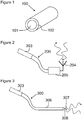
- Figure 1 shows a cable 100 comprising a polymer core 101 having an outer layer of cladding material 102 covering the polymer core 101.
- the cladding material 102 has a refractive index which is lower than the refractive index of the polymer core 101.
- the outer layer of cladding material 102 having a lower refractive index than the polymer core 101 results in a smaller critical angle between the polymer core 101 and the outer layer 102, meaning that electromagnetic waves within the polymer core 101 have an increased likelihood of being totally internally reflected down the polymer core 101 than escaping therefrom.
- the outer layer of cladding material 102 may comprise a metal cladding material.
- a metal cladding material 102 may provide for an increased wear resistance compared to other materials.
- the metal cladding material 102 may be sufficiently thin that it does not restrict any flexibility which the polymer core 101 may have.
- the cladding material 102 comprises copper or silver or a foam material. Copper may be particularly advantageous in some embodiments because it has low resistive loss.
- the polymer core 101 comprises a dielectric material which may be particularly suitable for guiding or transmitting electromagnetic waves therethrough without conducting electricity under normal operating conditions.
- the polymer core 101 may be made of a material, diameter and shape suitable for guiding electromagnetic waves of frequencies greater than 20 GHz through the cable 100.
- the polymer core 101 may comprise a hollow tube formed of a polymer material.
- the polymer core 101 may comprise a non-hollow material, such that the polymer core 101 comprises a solid cross-section throughout its longitudinal length.
- the solid cross-section is a filled cross-section and is flexible.
- the polymer core 101 in this example is not rigid nor unable to flex.
- Figure 2 shows a cable 200 connected to a component 203 and an antenna 204.
- the cable 200 is connected to the antenna 204 by way of a component 205.
- the component 205 may comprise a passive coupler configured to couple the cable to the antenna 204.
- the component may comprise an amplifier, termed here a preamplifier 205.
- the amplifier may comprise a Low Noise Amplifier (LNA), a Power Amplifier (PA) or a combination of a LNA and PA and having a switch device to switch a connection between them and the cable 200.
- the preamplifier may be configured to amplify signal received by the antenna 204.
- the component 203 may be a transceiver.
- the transceiver may be an integrated circuit (IC) that is configured to transmit data to and receive data from the antenna 204.
- the antenna 204 itself may be a single antenna or an antenna array and may be configured to couple electromagnetic waves to free space from the cable 200 and to couple electromagnetic waves from free space to the cable.
- the antenna 204 may be a patch antenna.
- Figure 3 shows a cable 300 connected to a component 303, the cable 300 comprising a non-radiative portion 306 and a radiative portion 307.
- the non-radiative portion 306 comprises a portion of the polymer core 101 over which the cladding material 102 extends. Because the cladding material 102 increases the likelihood of total internal reflection of the electromagnetic wave, portions of the polymer core 101 which are covered in the cladding material 102 are unlikely to radiate much or any of the electromagnetic waves carried by the cable. In contrast, a portion of the polymer core 101 over which the cladding material 102 does not extend has a much larger critical angle for total internal reflection and, therefore, electromagnetic waves within the cable 300 are more likely to couple to free space where the cladding material 102 is not present.
- the cable 300 comprises a first end face coupled to the component 303, a second end face and an elongate body between the first and second end faces.
- the second end face in this example, comprises the radiative portion 307. Due to the location of the radiative portion, the electromagnetic waves are directionally coupled to free space outward from the second end face of the cable.
- a separate antenna is not required, as the radiative portion 307 of the cable is capable of coupling electromagnetic waves to and from free space. This may be particularly advantageous for arrangements where there are spatial limitations or other limitations prevent the incorporation of a conventional antenna.
- Figure 4 shows a further example cable 400 connected to a component 403.
- the cable 400 comprising a non-radiative portion 406 and a plurality of radiative portions 407.
- the radiative portions 407 extend annularly around the polymer core 101 to form a plurality of continuous annular strips. It will be appreciated that a single annular strip may be provided or fewer or more than the number of strips shown in the figure may be provided. In some examples, all of the radiative portions 407 may extend wholly around the polymer core 101 or only some of them may extend wholly around the polymer core 101, with the remaining radiative portions 407 extending only partially around the polymer core 101.
- the annular strips cause electromagnetic waves to couple to, and be coupled from, free space in a plurality of radial directions from the cable. This may be particularly advantageous in embodiments wherein it is important to be able to couple to and from electromagnetic waves from all sides of the cable. For example, this may be advantageous for 5G mobile network implementations.
- Figure 5 comprises a further example cable 500 connected to a component 503.
- the cable 500 comprises a non-radiative portion 506 and a plurality of radiative portions 507.
- the radiative portions 507 in this example extend only partially around the polymer core 101 to form a plurality discontinuous annular strips. It will be appreciated that a single discontinuous annular strip may be provided orfewer or more discontinuous annular strips than are shown in the figure may be provided. Compared to the system of figure 4 , this system provides a plurality of directionally oriented radiative portions 507.
- the radiative portions 507 of this figure may be focussed to a narrower field of emission by making the radiative portions 507 correspondingly small, or a wide field of emission by extending the radiative portions 507 almost fully around the cable 500.
- the circumferential extent of the strips is provided to control the emission direction and emission angle range from the cable. While the radiative portions 507 in this example are shown as all facing the same radial direction with respect to the cross section of the cable 500, it will be appreciated that these radiative portions 507 could be formed at different radial locations around the cable 500.
- the end faces 408, 508 do not comprise radiative portions 407, 507, however, it will be appreciated that the end faces 408, 508 could comprise radiative portions 407, 507 in order to provide for coupling to and from free space in the axial direction of the cable 400, 500.
- the continuous and discontinuous annular strips of figures 4 and 5 are shown to be arranged substantially periodically. This may be particularly advantageous in certain embodiments, however, in other embodiments, the spacing between each of a plurality of annular radiative strip portions may be aperiodic, for example, where a larger signal detection or emission sensitivity is desired at one location along the cable 400, 500 compared to another.
- the radiative portions 407, 507 may be arranged in groups, each group comprising at least two radiative portions, the spacing between the groups greater than the spacing between radiative portions of one or both of the groups.
- the plurality of radiative portions 407, 507 in the examples of figures 4 and 5 may function as an antenna array, because the radiative portions can couple electromagnetic waves to and from free space.
- the diameter of the cable 400, 500 may be 5.88 mm, which couples to electromagnetic waves with frequencies of approximately 80 GHz.
- twenty radiative portions 407, 507 may be provided, each separated by 2.4 mm, providing a total length of the antenna array of approximately 5 cm.
- Each radiative portion 407, 507 may have a longitudinal width of 1.2 mm. This specific example may result in the emission of a single narrow planar beam of electromagnetic waves which is emitted from the cable 400, 500.
- the beam angle of electromagnetic waves emitted from a radiative portion 407, 507 of a cable 400, 500 may be varied by varying the frequency of emission.
- the beam angle may be varied over approximately 30 degrees by varying the frequency from 70 to 90 GHz. Scanning the beam angle may be advantageous, for example, in areas where there is little space available, such as in the rim of a vehicle door or outside vehicle mirror.
- Figure 6 shows still another example cable 600 connected to a component 603, the cable comprising a non-radiative portion 606 and a radiative portion 607, the cable 600 comprising a swell portion 609 having a diameter that monotonically varies from a first diameter at one end of the cable 600 (adjacent 607), to a second diameter at a position 610 along the longitudinal length of the cable 600, wherein the first diameter is larger than the second diameter.
- the radiative portion 607 is located at one of the end faces of the cable 608.
- the end face 608 of the cable 600 in this example, comprises the radiative portion and has a hemispherical, spherical section or parabolic shape.
- the swell portion 609 may, for example, comprise a conical shape.
- the hemispherical, spherical section or parabolic shape of the end face 608 of the end face 608 may be configured to focus the mm-wave beam in a direction that is parallel to the length of the cable 600 (at least at the end adjacent the end face 608).
- a hemispherical, spherical section or parabolic shaped radiative portion 607 may be incorporated onto the end face 608 of a cable 600 which does not comprise a swell portion 609.
- the swell portion may not increase in diameter monotonically.
- the cable 100, 200, 300, 400, 500, 600 is flexible.
- the cable may be sufficiently flexible such that it is capable of having a radius of curvature of less than one metre.
- a cable 100, 200, 300, 400, 500, 600 comprising polymer core 101 having an outer layer of a cladding material 102 may be particularly suited to providing the requisite flexibility.
- the cable may be deformable from a straight cable to a bent or coiled cable without causing permanent deformation to the cable 100, 200, 300, 400, 500, 600.
- the cable 100, 200, 300, 400, 500, 600 may be located within a car door and may, therefore, need to be flexible and bend when the door is opened, so as not to damage the cable 100, 200, 300, 400, 500, 600.
- the cable may be sufficiently flexible such that it may bend to have a radius of curvature of less than 1 metre, 0.8 m, 0.6 m, 0.4 m, 0.2 m, 0.1 m without permanent deformation or significant signal leakage.
- the cable may be sufficiently flexible such that it may bend to have a radius of curvature of less than 20 times or less than 10 times its diameter.
- the cable 100, 200, 300, 400, 500, 600 may be configured to guide electromagnetic waves of frequencies between 50 - 90 GHz, although in other examples frequencies of up to 200 or 300 GHz may be guided by such a cable.
- the cable 100, 200, 300, 400, 500, 600 may be configured to couple to electromagnetic waves of substantially 77 GHz.
- the cable 100, 200, 300, 400, 500, 600 may be configured to achieve this, for example, by being sized such that electromagnetic waves of these frequencies propagate through the cable 100, 200, 300, 400, 500, 600.
- the cross-sectional size and shape of the cable 100, 200, 300, 400, 500, 600 may determine the frequencies which most efficiently couple thereto, and those which are most likely to propagate through the cable 100, 200, 300, 400, 500, 600 efficiently.
- the diameter of a cable 100, 200, 300, 400, 500, 600 with a circular cross-section may be approximately equal to the wavelength of the waves to which the cable 100, 200, 300, 400, 500, 600 is configured to couple, thereby allowing for the propagation of single mode electromagnetic waves of substantially that wavelength.
- a cable 100, 200, 300, 400, 500, 600 having a diameter of substantially 1.7mm may be particularly suited to coupling to frequencies from 75 to 85 GHz.
- the cable 100, 200, 300, 400, 500, 600 may comprise a diameter larger than one wavelength of the electromagnetic waves with which coupling is intended.
- a cable 100, 200, 300, 400, 500, 600 may comprise a diameter of 5.8 mm which may be particularly suited to coupling to frequencies of 80 GHz in a multi-mode operation scheme.
- the radiative portions may comprise different patterns to those shown in figures 3 to 6 .
- the cross-sectional shape or size of the cable may be varied along its longitudinal length in order to result in a desired radiation pattern when electromagnetic waves are coupled to free space at radiative portions.
- Figure 6 shows an example of how the cross-sectional shape of the cable may be varied along its longitudinal length in order to provide for a parabolic or hemispherical radiative portion.
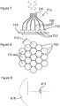
- FIG. 7 shows an apparatus 710 comprising an array of cables, the array of cables comprising a plurality of the cables 700.
- Each of the cables in the plurality of cables comprise a first end 712 and a second end 713.
- the second ends of the plurality of cables fan outwards such that the second ends are arranged in a spaced apart configuration.
- Each cable at the fanned end is coupled to a separate corresponding transceiver 713.
- the first end 711 of each of the plurality of cables 700 may be bundled together adjacent one another such that the spacing between two adjacent cables 700 at the first end 711 of the plurality of cables 700 is smaller than the spacing between two adjacent cables 700 of the second end 712 of the plurality of cables 700.
- the transceivers 713 are mounted on a printed circuit board 714, however, it will be appreciated that these transceivers 713 could be mounted in different ways or spread across different printed circuit boards.
- the first end 711 of each of the plurality of cables 700 may comprise a radiative portion or may be coupled to separate corresponding antennas.
- the plurality of radiative portions or antennas may provide an antenna array at the first end 711 of the plurality of cables 700, each radiative portion or antenna being coupled to a corresponding transceiver 713 via a cable 700.
- the transceiver-to-transceiver spacing may be mechanically decoupled from the antenna-to-antenna spacing. This allows for a transceiver 713 positioning that is optimised for minimal PCB cross-talk and maximal heat sinking while providing a closely coupled array of radiative portions or antennas.
- Figure 8 shows an example wherein the cables 700 may form an array of bundled cable ends at the first end 711 of the plurality of cables 700.
- the centre-to-centre spacing 712 of adjacent cables 700 may be between 0.2 - 3, 0.5 - 2 or 0.5 - 1 wavelengths of the electromagnetic waves to which the cables 700 are configured to be coupled.
- the first end 711 of each of the plurality of cables 700 is in direct contact with at least one adjacent cable 700. It will be appreciated that in some embodiments, these cables 700 may not be in direct contact, but may be spaced from one another.
- the spacing at the first end 711 of the plurality of cables 700 may not exceed the inter-cable spacing of the second ends of the cables 700, i.e., the fanned ends.
- the centre-to-centre spacing of the first ends 711 of the plurality of cables 700 may be between one half and one wavelength where the diameter of each cable is half a wavelength of the electromagnetic waves to which the cables 700 are configured to be coupled.
- Each cable of the plurality of cables 700 may comprise at least one preamplifier at either the first or second end of the cable 700.
- the preamplifier may be couplable to an antenna or it may be coupled to a radiative portion of the cable 700.
- Figure 9 shows, diagrammatically, an example of the bundled array of cable ends 711 of figure 8 as box 911 on the focal plane of a dielectric lens or parabolic mirror 915.
- the dielectric lens or parabolic mirror 915 may be configured to focus incoming electromagnetic waves on to the array of cable ends 711 by way of its shape and the relative positioning of the array of cable ends 911.
- the component 203, 303, 403, 503, 603 may be such a dielectric lens or other mm wave generator.
- the polymer core and cable is described as having a circular cross section. However, in other examples, the polymer core and/or cable may have other cross sections such as square or rectangular.
- Figure 10 shows a device 1000 that may include the cable or apparatus 710.
- the device may be an automotive vehicle which may comprise a car, a self-driving car, a truck, a lorry, a van, a caravan, a motorbike, a utility vehicle, a boat, a ship, a drone, an aircraft or an emergency services vehicle.
- the device 1000 may be an electronic device such as an automotive radar system, a 5G communications device or another device which may be configured to emit or receive electromagnetic waves.
- Figure 11 shows an example method 1100 of forming a cable.
- the method comprises the steps of forming 1101 an outer layer of cladding material on a polymer core, the outer layer at least partially covering the polymer core, the cladding material having a refractive index lower than the refractive index of the polymer core and the polymer core comprising a dielectric material.
- the outer layer of cladding material may be applied in a number of different ways such as wrapping, depositing or other techniques.
- One or more masks may be applied to the polymer core before providing the outer layer of cladding material so that, once the outer layer of cladding material has been provided, one or more radiative portions may be left without cladding material thereover.
- radiative portions may be formed by removing portions of the outer layer of cladding material after the cladding material has been provided onto the polymer core.
- one or more instructions or steps discussed herein are automated.
- the terms automated or automatically mean controlled operation of an apparatus, system, and/or process using computers and/or mechanical/electrical devices without the necessity of human intervention, observation, effort and/or decision.
- any components said to be coupled may be coupled or connected either directly or indirectly.
- additional components may be located between the two components that are said to be coupled.
Landscapes
- Radar Systems Or Details Thereof (AREA)
- Variable-Direction Aerials And Aerial Arrays (AREA)
Abstract
Description
- The present disclosure relates to a cable configured to guide electromagnetic waves, a method of making thereof, an apparatus comprising an array of said cables and an automotive vehicle.
- According to a first aspect of the present disclosure there is provided a cable configured to guide electromagnetic waves therethrough comprising a polymer core having an outer layer of cladding material, the outer layer at least partially covering the polymer core, the cladding material having a refractive index lower than the refractive index of the polymer core, the polymer core comprising a dielectric material.
- In one or more embodiments, the cable may be configured to guide electromagnetic waves of frequencies greater than 20 GHz through the cable. In one or more embodiments, the cable may comprise a diameter of less than 15 mm, less than 10 mm, less than 8 mm or less than 5 mm.
- In one or more embodiments, the cable may be configured to guide the electromagnetic waves between a first antenna and one or more of a second antenna, an antenna array and a transceiver.
- In one or more embodiments, the polymer core may be non-hollow. In one or more embodiments, the polymer core may comprise an elongate solid central section of the cable.
- In one or more embodiments, the cladding material may comprise a metal cladding material. In one or more embodiments, the cladding material may comprise copper. In one or more embodiments, the cladding material may be in direct physical contact with the polymer core. In one or more embodiments, the cladding material comprises a foam.
- In one or more embodiments, the cable may comprise a non-radiative portion and at least one radiative portion, wherein the non-radiative portion may comprise a portion of the cable wherein the cladding material extends over the polymer core and the radiative portion may comprise a portion of the cable wherein the cladding material does not extend over the polymer core, the radiative portion configured to couple electromagnetic waves to free space.
- Thus, in one or more embodiment, the non-radiative portion, being covered in cladding material substantially prevents electromagnetic waves leaving the cable, the radiative portions, having the polymer core exposed to free space, allows for emission of electromagnetic waves from the cable and the receipt of electromagnetic waves by the cable and thus the radiative portions form an antenna.
- In one or more embodiments, the at least one radiative portion may extend one or more of: i) partially around the polymer core to form a discontinuous annular strip; and ii) annularly around the polymer core to form a continuous annular strip.
- In one or more embodiments, the cable may be connectable to an antenna to provide the electromagnetic waves thereto. In one or more embodiments, the antenna may be a patch antenna.
- In one or more embodiments, the polymer core may comprise an elongate body having a first terminal end face and a second terminal end face separated by an at least one elongate side, at least one of the at least one radiative portions comprising one of the first and second terminal end faces. In one or more embodiments, the non-radiative portion may comprise the elongate side, such as a majority or all of the elongate side.
- In one or more embodiments, the at least one of the first and second terminal end faces comprising the radiative portion may have one of a hemispherical, spherical section or parabolic shape.
- In one or more embodiments, the cable may comprise a plurality of radiative portions, wherein the plurality of radiative portions are regularly spaced along the longitudinal length of the cable. In one or more embodiments, the plurality of radiative portions may form a grating.
- In one or more embodiments, the cable may comprise a swell portion having a diameter that monotonically varies from a first diameter at one end of the cable, to a second diameter at a position along the longitudinal length of the cable, wherein the first diameter may be larger than the second diameter.
- In one or more embodiments, the cable may be flexible such that it is capable of having a radius of curvature of less than 1 metre. In one or more embodiments, the cable may be flexible such that it is capable of having a radius of curvature of less than 1 metre without permanently deforming the cable. In one or more embodiments, the radius of curvature of the cable along its longitudinal length may be variable between a straight cable and a radius of curvature of up to ten times the diameter of the cable.
- In one or more embodiments, the cable may be configured to guide electromagnetic waves of frequencies between 50 - 300 GHz, 50 - 200 GHz or 50 - 100 GHz through the cable. In one or more embodiments, the cable may be configured to guide electromagnetic waves of 65 - 85 GHz through the cable. In one or more embodiments, the cable may be configured to guide electromagnetic waves of 77 GHz through the cable. In one or more embodiments, the polymer core of the cable may comprise a circular cross section having a diameter of between 1 mm and 5 mm or less than 5mm.
- According to a second aspect of the present disclosure, there is provided an apparatus comprising an array of cables, the array of cables comprising a plurality of the cables of the first aspect, each of the cables of the plurality of cables comprising a first end and a second end, the first ends of the cables bundled together adjacent one another, the cables configured to fan out at the second ends such that the second ends are arranged in a spaced apart configuration, the fanned end of each cable coupling to a separate corresponding transceiver.
- In one or more embodiments, the apparatus may further include a plurality of amplifiers, each cable of the plurality of cables coupled to one of the plurality of amplifiers at one of the first end or the second end of the cable, the amplifier coupled to an antenna.
- According to a third aspect of the present disclosure, there is provided a device comprising one of an automotive vehicle or electronic device including the cable of the first aspect or the apparatus of the second aspect.
- According to a fourth aspect of the present disclosure, there is provided a method of forming a cable configured to guide electromagnetic waves therethrough comprising: forming an outer layer of cladding material on a polymer core, the outer layer at least partially covering the polymer core, the cladding material having a refractive index lower than the refractive index of the polymer core and the polymer core comprising a dielectric material.
- In one or more embodiments, radiative portions to provide for coupling of electromagnetic waves to and/or from the cable may be formed by one or more of:
- during the step of forming an outer layer of cladding material on the polymer core, selectively forming the outer layer of cladding material on the polymer core such that there is an absence of cladding material over selected portions of the polymer core; and
- after the step of forming an outer layer of cladding material on the polymer core, removing portions of the cladding material in order to provide an absence of cladding material over selected portions of the polymer core.
- While the disclosure is amenable to various modifications and alternative forms, specifics thereof have been shown by way of example in the drawings and will be described in detail. It should be understood, however, that other embodiments, beyond the particular embodiments described, are possible as well. All modifications, equivalents, and alternative embodiments falling within the spirit and scope of the appended claims are covered as well.
- The above discussion is not intended to represent every example embodiment or every implementation within the scope of the current or future Claim sets. The figures and Detailed Description that follow also exemplify various example embodiments. Various example embodiments may be more completely understood in consideration of the following Detailed Description in connection with the accompanying Drawings.
- One or more embodiments will now be described by way of example only with reference to the accompanying drawings in which:
-
Figure 1 shows an example embodiment of a cable comprising a polymer core having an outer layer; -
Figure 2 shows an example embodiment of a system comprising a cable and an antenna; -
Figure 3 shows an example embodiment of a system comprising a cable having a radiative portion; -
Figure 4 shows an example embodiment of a system comprising a cable having a plurality of continuous annular radiative strip portions around the polymer core; -
Figure 5 shows an example embodiment of a system comprising a cable having a plurality of discontinuous annular radiative strip portions extending partially around the polymer core; -
Figure 6 shows an example embodiment of a system comprising a cable having a swell portion and a radiative portion at a hemispherical or parabolic end of the cable; -
Figure 7 shows an example embodiment of an apparatus comprising an array of cables, the cables fanning outwards, the fanned ends coupled to separate components; -
Figure 8 shows an example embodiment of an array of cables; -
Figure 9 shows an example embodiment of an array of cable ends placed on the focal plane of a dielectric lens or parabolic mirror; -
Figure 10 shows an example embodiment of an automotive vehicle; and -
Figure 11 shows an example embodiment of a method of forming a cable. - Radar systems are becoming increasingly common in the automotive industry. These systems are used, for example, as sensors for assisted parking, automatic cruise control speed adjustment (adaptive cruise control), headway alert, collision warning and mitigation and brake support. In order to enable the range of uses for which radar systems may employed, it may be necessary to incorporate individual antennas or antenna arrays at a number of locations around the vehicle. Some locations on a vehicle may present challenges for the incorporation of an antenna or antenna array, such as portions of the vehicle which are configured to move relative to one another, such as the doors in relation to the chassis.
- The antennas for automotive radar systems that use frequencies around 77 GHz radar typically reside on a vehicle's perimeter. Antennas for this purpose cannot be positioned behind metal, so the number of suitable radar positions may be limited and also impose limitations on the form factor of the antenna. On the other hand, the location requirements for a transceiver which may receive signals from the antenna can be quite different: the transceiver can be behind a metal sheet, but needs to reside at a location in the vehicle where sufficient supply power and heat sinking capability is available. The vehicle's perimeter might therefore not be the optimal location for the transceiver to reside.
- For the above reasons, it may be beneficial in some embodiments to allow for some spacing between a transceiver and an antenna or antenna array. Also, a larger distance between different antennas may be beneficial for increasing the overall monitoring area of the radar system. In some examples, the antenna-to-antenna and transceiver-to-antenna interconnect needs to be flexible, i.e. needs to adapt to the contours of the vehicle. This may be especially true in situations where the antenna elements are residing in a door or other moving element, such as an external mirror, while the transceiver is fixed to the vehicle body.
- It will be understood that the application of the present disclosure is not limited to automotive radar systems. For example, the antenna described herein may also be used in radar systems where similar requirements of adaptability and flexibility apply, such as in radar systems used for gesture sensing, human presence detection, and gaming. Furthermore, the disclosure may be applied to non-radar applications, such as point-to-point communication, mm-wave point-to-point communication for backhaul and 5G mobile networks.
-
Figure 1 shows acable 100 comprising apolymer core 101 having an outer layer ofcladding material 102 covering thepolymer core 101. - The
cladding material 102 has a refractive index which is lower than the refractive index of thepolymer core 101. The outer layer ofcladding material 102 having a lower refractive index than thepolymer core 101 results in a smaller critical angle between thepolymer core 101 and theouter layer 102, meaning that electromagnetic waves within thepolymer core 101 have an increased likelihood of being totally internally reflected down thepolymer core 101 than escaping therefrom. - In some examples, the outer layer of
cladding material 102 may comprise a metal cladding material. Ametal cladding material 102 may provide for an increased wear resistance compared to other materials. Themetal cladding material 102 may be sufficiently thin that it does not restrict any flexibility which thepolymer core 101 may have. In some examples, thecladding material 102 comprises copper or silver or a foam material. Copper may be particularly advantageous in some embodiments because it has low resistive loss. - The
polymer core 101 comprises a dielectric material which may be particularly suitable for guiding or transmitting electromagnetic waves therethrough without conducting electricity under normal operating conditions. In particular, thepolymer core 101 may be made of a material, diameter and shape suitable for guiding electromagnetic waves of frequencies greater than 20 GHz through thecable 100. - In some embodiments, the
polymer core 101 may comprise a hollow tube formed of a polymer material. Alternatively, thepolymer core 101 may comprise a non-hollow material, such that thepolymer core 101 comprises a solid cross-section throughout its longitudinal length. In this example, it will be understood that the solid cross-section is a filled cross-section and is flexible. Thus, thepolymer core 101 in this example is not rigid nor unable to flex. -
Figure 2 shows acable 200 connected to acomponent 203 and anantenna 204. In this example, thecable 200 is connected to theantenna 204 by way of acomponent 205. Thecomponent 205 may comprise a passive coupler configured to couple the cable to theantenna 204. However, in other examples and as provided here, the component may comprise an amplifier, termed here apreamplifier 205. However, it will be appreciated that the amplifier may comprise a Low Noise Amplifier (LNA), a Power Amplifier (PA) or a combination of a LNA and PA and having a switch device to switch a connection between them and thecable 200. The preamplifier may be configured to amplify signal received by theantenna 204. In some embodiments, thecomponent 203 may be a transceiver. The transceiver may be an integrated circuit (IC) that is configured to transmit data to and receive data from theantenna 204. Theantenna 204 itself may be a single antenna or an antenna array and may be configured to couple electromagnetic waves to free space from thecable 200 and to couple electromagnetic waves from free space to the cable. In some embodiments, theantenna 204 may be a patch antenna. -
Figure 3 shows acable 300 connected to acomponent 303, thecable 300 comprising anon-radiative portion 306 and aradiative portion 307. In this example, thenon-radiative portion 306 comprises a portion of thepolymer core 101 over which thecladding material 102 extends. Because thecladding material 102 increases the likelihood of total internal reflection of the electromagnetic wave, portions of thepolymer core 101 which are covered in thecladding material 102 are unlikely to radiate much or any of the electromagnetic waves carried by the cable. In contrast, a portion of thepolymer core 101 over which thecladding material 102 does not extend has a much larger critical angle for total internal reflection and, therefore, electromagnetic waves within thecable 300 are more likely to couple to free space where thecladding material 102 is not present. - In the example of
figure 3 , thecable 300 comprises a first end face coupled to thecomponent 303, a second end face and an elongate body between the first and second end faces. The second end face, in this example, comprises theradiative portion 307. Due to the location of the radiative portion, the electromagnetic waves are directionally coupled to free space outward from the second end face of the cable. In this case, a separate antenna is not required, as theradiative portion 307 of the cable is capable of coupling electromagnetic waves to and from free space. This may be particularly advantageous for arrangements where there are spatial limitations or other limitations prevent the incorporation of a conventional antenna. -
Figure 4 shows afurther example cable 400 connected to acomponent 403. Thecable 400 comprising anon-radiative portion 406 and a plurality ofradiative portions 407. In this example, theradiative portions 407 extend annularly around thepolymer core 101 to form a plurality of continuous annular strips. It will be appreciated that a single annular strip may be provided or fewer or more than the number of strips shown in the figure may be provided. In some examples, all of theradiative portions 407 may extend wholly around thepolymer core 101 or only some of them may extend wholly around thepolymer core 101, with the remainingradiative portions 407 extending only partially around thepolymer core 101. The annular strips cause electromagnetic waves to couple to, and be coupled from, free space in a plurality of radial directions from the cable. This may be particularly advantageous in embodiments wherein it is important to be able to couple to and from electromagnetic waves from all sides of the cable. For example, this may be advantageous for 5G mobile network implementations. -
Figure 5 comprises afurther example cable 500 connected to acomponent 503. Thecable 500 comprises anon-radiative portion 506 and a plurality ofradiative portions 507. Theradiative portions 507 in this example extend only partially around thepolymer core 101 to form a plurality discontinuous annular strips. It will be appreciated that a single discontinuous annular strip may be provided orfewer or more discontinuous annular strips than are shown in the figure may be provided. Compared to the system offigure 4 , this system provides a plurality of directionally orientedradiative portions 507. Theradiative portions 507 of this figure may be focussed to a narrower field of emission by making theradiative portions 507 correspondingly small, or a wide field of emission by extending theradiative portions 507 almost fully around thecable 500. Thus, in one or more examples, the circumferential extent of the strips is provided to control the emission direction and emission angle range from the cable. While theradiative portions 507 in this example are shown as all facing the same radial direction with respect to the cross section of thecable 500, it will be appreciated that theseradiative portions 507 could be formed at different radial locations around thecable 500. - In the examples of
figures 4 and 5 , the end faces 408, 508 do not compriseradiative portions radiative portions cable figures 4 and 5 are shown to be arranged substantially periodically. This may be particularly advantageous in certain embodiments, however, in other embodiments, the spacing between each of a plurality of annular radiative strip portions may be aperiodic, for example, where a larger signal detection or emission sensitivity is desired at one location along thecable radiative portions - The plurality of
radiative portions figures 4 and 5 may function as an antenna array, because the radiative portions can couple electromagnetic waves to and from free space. In one example, the diameter of thecable radiative portions radiative portion cable radiative portion cable -
Figure 6 shows still anotherexample cable 600 connected to acomponent 603, the cable comprising anon-radiative portion 606 and aradiative portion 607, thecable 600 comprising aswell portion 609 having a diameter that monotonically varies from a first diameter at one end of the cable 600 (adjacent 607), to a second diameter at aposition 610 along the longitudinal length of thecable 600, wherein the first diameter is larger than the second diameter. In this example, theradiative portion 607 is located at one of the end faces of thecable 608. Theend face 608 of thecable 600, in this example, comprises the radiative portion and has a hemispherical, spherical section or parabolic shape. Theswell portion 609 may, for example, comprise a conical shape. The hemispherical, spherical section or parabolic shape of theend face 608 of theend face 608 may be configured to focus the mm-wave beam in a direction that is parallel to the length of the cable 600 (at least at the end adjacent the end face 608). It will be appreciated that a hemispherical, spherical section or parabolic shapedradiative portion 607 may be incorporated onto theend face 608 of acable 600 which does not comprise aswell portion 609. In other embodiments, the swell portion may not increase in diameter monotonically. - In each of the embodiments of
figures 1 - 6 , thecable cable polymer core 101 having an outer layer of acladding material 102 may be particularly suited to providing the requisite flexibility. The cable may be deformable from a straight cable to a bent or coiled cable without causing permanent deformation to thecable cable cable - The
cable cable cable cable cable cable cable cable cable cable cable cable - In yet further examples, the radiative portions may comprise different patterns to those shown in
figures 3 to 6 . In some examples, the cross-sectional shape or size of the cable may be varied along its longitudinal length in order to result in a desired radiation pattern when electromagnetic waves are coupled to free space at radiative portions.Figure 6 shows an example of how the cross-sectional shape of the cable may be varied along its longitudinal length in order to provide for a parabolic or hemispherical radiative portion. -
Figure 7 shows anapparatus 710 comprising an array of cables, the array of cables comprising a plurality of thecables 700. Each of the cables in the plurality of cables comprise afirst end 712 and asecond end 713. In this example, the second ends of the plurality of cables fan outwards such that the second ends are arranged in a spaced apart configuration. Each cable at the fanned end is coupled to a separatecorresponding transceiver 713. Thefirst end 711 of each of the plurality ofcables 700 may be bundled together adjacent one another such that the spacing between twoadjacent cables 700 at thefirst end 711 of the plurality ofcables 700 is smaller than the spacing between twoadjacent cables 700 of thesecond end 712 of the plurality ofcables 700. In this example, thetransceivers 713 are mounted on a printedcircuit board 714, however, it will be appreciated that thesetransceivers 713 could be mounted in different ways or spread across different printed circuit boards. - The
first end 711 of each of the plurality ofcables 700 may comprise a radiative portion or may be coupled to separate corresponding antennas. The plurality of radiative portions or antennas may provide an antenna array at thefirst end 711 of the plurality ofcables 700, each radiative portion or antenna being coupled to acorresponding transceiver 713 via acable 700. - By using a plurality of
cables 700 having a bundled end and a fanned end, such as those described above, to connect each radiative portion or antenna to acorresponding transceiver 713, the transceiver-to-transceiver spacing may be mechanically decoupled from the antenna-to-antenna spacing. This allows for atransceiver 713 positioning that is optimised for minimal PCB cross-talk and maximal heat sinking while providing a closely coupled array of radiative portions or antennas. -
Figure 8 shows an example wherein thecables 700 may form an array of bundled cable ends at thefirst end 711 of the plurality ofcables 700. The centre-to-centre spacing 712 ofadjacent cables 700 may be between 0.2 - 3, 0.5 - 2 or 0.5 - 1 wavelengths of the electromagnetic waves to which thecables 700 are configured to be coupled. In the example offigure 8 , thefirst end 711 of each of the plurality ofcables 700 is in direct contact with at least oneadjacent cable 700. It will be appreciated that in some embodiments, thesecables 700 may not be in direct contact, but may be spaced from one another. However, the spacing at thefirst end 711 of the plurality ofcables 700 may not exceed the inter-cable spacing of the second ends of thecables 700, i.e., the fanned ends. For example, in some embodiments, the centre-to-centre spacing of the first ends 711 of the plurality ofcables 700 may be between one half and one wavelength where the diameter of each cable is half a wavelength of the electromagnetic waves to which thecables 700 are configured to be coupled. Each cable of the plurality ofcables 700 may comprise at least one preamplifier at either the first or second end of thecable 700. The preamplifier may be couplable to an antenna or it may be coupled to a radiative portion of thecable 700. -
Figure 9 shows, diagrammatically, an example of the bundled array of cable ends 711 offigure 8 asbox 911 on the focal plane of a dielectric lens orparabolic mirror 915. The dielectric lens orparabolic mirror 915 may be configured to focus incoming electromagnetic waves on to the array of cable ends 711 by way of its shape and the relative positioning of the array of cable ends 911. Thecomponent - In the above examples, the polymer core and cable is described as having a circular cross section. However, in other examples, the polymer core and/or cable may have other cross sections such as square or rectangular.
-
Figure 10 shows adevice 1000 that may include the cable orapparatus 710. The device may be an automotive vehicle which may comprise a car, a self-driving car, a truck, a lorry, a van, a caravan, a motorbike, a utility vehicle, a boat, a ship, a drone, an aircraft or an emergency services vehicle. - The
device 1000 may be an electronic device such as an automotive radar system, a 5G communications device or another device which may be configured to emit or receive electromagnetic waves. -
Figure 11 shows an example method 1100 of forming a cable. The method comprises the steps of forming 1101 an outer layer of cladding material on a polymer core, the outer layer at least partially covering the polymer core, the cladding material having a refractive index lower than the refractive index of the polymer core and the polymer core comprising a dielectric material. It will be appreciated that the outer layer of cladding material may be applied in a number of different ways such as wrapping, depositing or other techniques. One or more masks may be applied to the polymer core before providing the outer layer of cladding material so that, once the outer layer of cladding material has been provided, one or more radiative portions may be left without cladding material thereover. Alternatively, radiative portions may be formed by removing portions of the outer layer of cladding material after the cladding material has been provided onto the polymer core. - The instructions and/or flowchart steps in the above figures can be executed in any order, unless a specific order is explicitly stated. Also, those skilled in the art will recognize that while one example set of instructions/method has been discussed, the material in this specification can be combined in a variety of ways to yield other examples as well, and are to be understood within a context provided by this detailed description.
- In one example, one or more instructions or steps discussed herein are automated. The terms automated or automatically (and like variations thereof) mean controlled operation of an apparatus, system, and/or process using computers and/or mechanical/electrical devices without the necessity of human intervention, observation, effort and/or decision.
- It will be appreciated that any components said to be coupled may be coupled or connected either directly or indirectly. In the case of indirect coupling, additional components may be located between the two components that are said to be coupled.
- In this specification, example embodiments have been presented in terms of a selected set of details. However, a person of ordinary skill in the art would understand that many other example embodiments may be practiced which include a different selected set of these details. It is intended that the following claims cover all possible example embodiments.
Claims (15)
- A cable configured to guide electromagnetic waves therethrough comprising a polymer core having an outer layer of cladding material, the outer layer at least partially covering the polymer core, the cladding material having a refractive index lower than the refractive index of the polymer core, the polymer core comprising a dielectric material.
- The cable of claim 1, wherein the cable is arranged with and connected to a first antenna and configured to guide the electromagnetic waves between the first antenna and one or more of a second antenna, an antenna array and a transceiver.
- The cable of any preceding claim, wherein the polymer core is non-hollow.
- The cable of any preceding claim, wherein the cladding material comprises a metal cladding material.
- The cable of any preceding claim comprising a non-radiative portion and at least one radiative portion, wherein the non-radiative portion comprises a portion of the cable wherein the cladding material extends over the polymer core and the radiative portion comprises a portion of the cable wherein the cladding material does not extend over the polymer core, the radiative portion configured to couple electromagnetic waves to free space.
- The cable of claim 5, wherein the at least one radiative portion extends one or more ofi) partially around the polymer core to form a discontinuous annular strip; andii) annularly around the polymer core to form a continuous annular strip
- The cable of claim 5, wherein the polymer core comprises an elongate body having a first terminal end face and a second terminal end face separated by an at least one elongate side, at least one of the at least one radiative portions comprising one of the first and second terminal end faces.
- The cable of claim 7, wherein the at least one of the first and second terminal end faces comprising the radiative portion has one of a hemispherical, spherical section and parabolic shape.
- The cable of claim 5, comprising a plurality of radiative portions, wherein the plurality of radiative portions are spaced regularly along the longitudinal length of at least part of the cable.
- The cable of any preceding claim comprising a swell portion having a diameter that monotonically varies from a first diameter at one end of the cable, to a second diameter at a position along a longitudinal length of the cable, wherein the first diameter is larger than the second diameter.
- The cable of any preceding claim, wherein the cable is flexible such that it is capable of having a radius of curvature of less than 1 metre.
- An apparatus comprising an array of cables, the array of cables comprising a plurality of the cables of claims 1 - 11, each of the cables of the plurality of cables comprising a first end and a second end, the first ends of the cables bundled together adjacent one another to form a bundled end of the array, the cables configured to fan out such that the second ends are arranged in a spaced apart configuration to form a fanned end of the array, each of the second ends coupled to a separate corresponding transceiver.
- The apparatus of claim 12 including a plurality of amplifiers, each cable of the plurality of cables comprising one of the plurality of amplifiers at one of the first end or the second end of the cable, the amplifier coupled to an antenna.
- A device comprising one of an automotive vehicle or electronic device including the cable of any one of claims 1 - 11.
- A method of forming a cable configured to guide electromagnetic waves therethrough comprising:forming an outer layer of cladding material on a polymer core, the outer layer at least partially covering the polymer core, the cladding material having a refractive index lower than the refractive index of the polymer core and the polymer core comprising a dielectric material.
Priority Applications (1)
| Application Number | Priority Date | Filing Date | Title |
|---|---|---|---|
| EP17181483.3A EP3429025A1 (en) | 2017-07-14 | 2017-07-14 | A cable, method of making thereof and corresponding apparatus |
Applications Claiming Priority (1)
| Application Number | Priority Date | Filing Date | Title |
|---|---|---|---|
| EP17181483.3A EP3429025A1 (en) | 2017-07-14 | 2017-07-14 | A cable, method of making thereof and corresponding apparatus |
Publications (1)
| Publication Number | Publication Date |
|---|---|
| EP3429025A1 true EP3429025A1 (en) | 2019-01-16 |
Family
ID=59350794
Family Applications (1)
| Application Number | Title | Priority Date | Filing Date |
|---|---|---|---|
| EP17181483.3A Withdrawn EP3429025A1 (en) | 2017-07-14 | 2017-07-14 | A cable, method of making thereof and corresponding apparatus |
Country Status (1)
| Country | Link |
|---|---|
| EP (1) | EP3429025A1 (en) |
Cited By (3)
| Publication number | Priority date | Publication date | Assignee | Title |
|---|---|---|---|---|
| JP2021114766A (en) * | 2020-01-17 | 2021-08-05 | 株式会社Nttドコモ | Wireless antenna and wireless communication system |
| CN113906305A (en) * | 2019-05-27 | 2022-01-07 | 大众汽车股份公司 | Vehicle window for radar environment detection and manufacturing method |
| EP4329087A1 (en) * | 2022-08-26 | 2024-02-28 | indie Semiconductor FFO GmbH | Dielectric waveguide data interface and sensor system |
Citations (6)
| Publication number | Priority date | Publication date | Assignee | Title |
|---|---|---|---|---|
| JP4537928B2 (en) * | 2005-10-04 | 2010-09-08 | 日本放送協会 | Antenna device |
| WO2013192337A1 (en) * | 2012-06-19 | 2013-12-27 | Waveconnex, Inc. | Dielectric conduits for ehf communications |
| US20150295307A1 (en) * | 2014-04-09 | 2015-10-15 | Texas Instruments Incorporated | Dielectric Waveguide with Embedded Antenna |
| US20160240907A1 (en) * | 2015-02-12 | 2016-08-18 | Texas Instruments Incorporated | Dielectric Waveguide Radar Signal Distribution |
| US20160293557A1 (en) * | 2015-03-30 | 2016-10-06 | Sony Corporation | Package and antenna apparatus including package |
| US20170033465A1 (en) * | 2015-07-14 | 2017-02-02 | At&T Intellectual Property I, L.P. | Apparatus and methods for sending or receiving electromagnetic signals |
-
2017
- 2017-07-14 EP EP17181483.3A patent/EP3429025A1/en not_active Withdrawn
Patent Citations (6)
| Publication number | Priority date | Publication date | Assignee | Title |
|---|---|---|---|---|
| JP4537928B2 (en) * | 2005-10-04 | 2010-09-08 | 日本放送協会 | Antenna device |
| WO2013192337A1 (en) * | 2012-06-19 | 2013-12-27 | Waveconnex, Inc. | Dielectric conduits for ehf communications |
| US20150295307A1 (en) * | 2014-04-09 | 2015-10-15 | Texas Instruments Incorporated | Dielectric Waveguide with Embedded Antenna |
| US20160240907A1 (en) * | 2015-02-12 | 2016-08-18 | Texas Instruments Incorporated | Dielectric Waveguide Radar Signal Distribution |
| US20160293557A1 (en) * | 2015-03-30 | 2016-10-06 | Sony Corporation | Package and antenna apparatus including package |
| US20170033465A1 (en) * | 2015-07-14 | 2017-02-02 | At&T Intellectual Property I, L.P. | Apparatus and methods for sending or receiving electromagnetic signals |
Non-Patent Citations (1)
| Title |
|---|
| CHONG ZHANG ET AL: "Radiation Characteristic of the Leaky Circular Waveguide With Periodic Slots", IEEE ANTENNAS AND WIRELESS PROPAGATION LETTERS, IEEE, PISCATAWAY, NJ, US, vol. 11, 1 January 2012 (2012-01-01), pages 503 - 506, XP011489228, ISSN: 1536-1225, DOI: 10.1109/LAWP.2012.2199275 * |
Cited By (3)
| Publication number | Priority date | Publication date | Assignee | Title |
|---|---|---|---|---|
| CN113906305A (en) * | 2019-05-27 | 2022-01-07 | 大众汽车股份公司 | Vehicle window for radar environment detection and manufacturing method |
| JP2021114766A (en) * | 2020-01-17 | 2021-08-05 | 株式会社Nttドコモ | Wireless antenna and wireless communication system |
| EP4329087A1 (en) * | 2022-08-26 | 2024-02-28 | indie Semiconductor FFO GmbH | Dielectric waveguide data interface and sensor system |
Similar Documents
| Publication | Publication Date | Title |
|---|---|---|
| CN107086350B (en) | Impedance surface treatment for reducing surface waves and improving antenna gain on glass | |
| US10777878B2 (en) | Radome and vehicular radar apparatus comprising same | |
| EP3429025A1 (en) | A cable, method of making thereof and corresponding apparatus | |
| US20190128624A1 (en) | Enhanced gain antenna systems employing fractal metamaterials | |
| US7218281B2 (en) | Artificial impedance structure | |
| JPH08146131A (en) | In-vehicle radar device | |
| CN113394560B (en) | Antenna assembly, antenna device and movable platform | |
| US8179327B1 (en) | Subsurface deployable antenna array | |
| US12489224B2 (en) | Antenna apparatus, method for producing antenna apparatus, radar, and terminal | |
| US10249960B2 (en) | Distributed antenna system and method of manufacturing a distributed antenna system | |
| KR20230011707A (en) | Metamaterial surface cover for ready-made radars and commercial radars to improve the radiation patterns and dectection range, radar antenna, and radar antenna structure using metamaterial surface cover | |
| CN1183174A (en) | Antennas and Antenna Devices | |
| US9595757B2 (en) | Integral RF-optical phased array module | |
| CN102723578B (en) | Satellite antenna for satellite communication in motion | |
| KR102754606B1 (en) | WIRELESS POWER CHARGING APPARATUS FOR CHARGING IoT DEVICE | |
| JP4554485B2 (en) | Leaky coaxial cable system | |
| US9153861B2 (en) | Using a vehicle structure as a medium for communication and power distribution | |
| CN220066091U (en) | Ultra-wideband glass antenna, car window glass and vehicle | |
| WO2019198448A1 (en) | Radome design for improving radar system performance for semi- and full-autonomous driving applications | |
| EP4016740B1 (en) | Twin line fed dipole array antenna | |
| KR102666817B1 (en) | Apparatus for FMCW | |
| KR101833038B1 (en) | A vehicle radar antenna system for preventing collision | |
| KR102266625B1 (en) | Omni Directional Antenna Apparatus for Vehicle | |
| CN113207319A (en) | Vehicle glazing | |
| CN222126973U (en) | Unmanned aerial vehicle monitoring direction finding antenna of coplane overall arrangement |
Legal Events
| Date | Code | Title | Description |
|---|---|---|---|
| PUAI | Public reference made under article 153(3) epc to a published international application that has entered the european phase |
Free format text: ORIGINAL CODE: 0009012 |
|
| AK | Designated contracting states |
Kind code of ref document: A1 Designated state(s): AL AT BE BG CH CY CZ DE DK EE ES FI FR GB GR HR HU IE IS IT LI LT LU LV MC MK MT NL NO PL PT RO RS SE SI SK SM TR |
|
| AX | Request for extension of the european patent |
Extension state: BA ME |
|
| 17P | Request for examination filed |
Effective date: 20190716 |
|
| RBV | Designated contracting states (corrected) |
Designated state(s): AL AT BE BG CH CY CZ DE DK EE ES FI FR GB GR HR HU IE IS IT LI LT LU LV MC MK MT NL NO PL PT RO RS SE SI SK SM TR |
|
| 17Q | First examination report despatched |
Effective date: 20191122 |
|
| STAA | Information on the status of an ep patent application or granted ep patent |
Free format text: STATUS: THE APPLICATION IS DEEMED TO BE WITHDRAWN |
|
| 18D | Application deemed to be withdrawn |
Effective date: 20200603 |