EP3428801B1 - Planungsverfahren und elektronische vorrichtung - Google Patents
Planungsverfahren und elektronische vorrichtung Download PDFInfo
- Publication number
- EP3428801B1 EP3428801B1 EP17769373.6A EP17769373A EP3428801B1 EP 3428801 B1 EP3428801 B1 EP 3428801B1 EP 17769373 A EP17769373 A EP 17769373A EP 3428801 B1 EP3428801 B1 EP 3428801B1
- Authority
- EP
- European Patent Office
- Prior art keywords
- processor
- data
- working mode
- busy
- time slice
- Prior art date
- Legal status (The legal status is an assumption and is not a legal conclusion. Google has not performed a legal analysis and makes no representation as to the accuracy of the status listed.)
- Active
Links
Images




Classifications
-
- G—PHYSICS
- G06—COMPUTING OR CALCULATING; COUNTING
- G06F—ELECTRIC DIGITAL DATA PROCESSING
- G06F11/00—Error detection; Error correction; Monitoring
- G06F11/30—Monitoring
- G06F11/3003—Monitoring arrangements specially adapted to the computing system or computing system component being monitored
- G06F11/301—Monitoring arrangements specially adapted to the computing system or computing system component being monitored where the computing system is a virtual computing platform, e.g. logically partitioned systems
-
- G—PHYSICS
- G06—COMPUTING OR CALCULATING; COUNTING
- G06F—ELECTRIC DIGITAL DATA PROCESSING
- G06F9/00—Arrangements for program control, e.g. control units
- G06F9/06—Arrangements for program control, e.g. control units using stored programs, i.e. using an internal store of processing equipment to receive or retain programs
- G06F9/46—Multiprogramming arrangements
- G06F9/48—Program initiating; Program switching, e.g. by interrupt
- G06F9/4806—Task transfer initiation or dispatching
- G06F9/4843—Task transfer initiation or dispatching by program, e.g. task dispatcher, supervisor, operating system
- G06F9/4881—Scheduling strategies for dispatcher, e.g. round robin, multi-level priority queues
-
- G—PHYSICS
- G06—COMPUTING OR CALCULATING; COUNTING
- G06F—ELECTRIC DIGITAL DATA PROCESSING
- G06F11/00—Error detection; Error correction; Monitoring
- G06F11/30—Monitoring
-
- G—PHYSICS
- G06—COMPUTING OR CALCULATING; COUNTING
- G06F—ELECTRIC DIGITAL DATA PROCESSING
- G06F11/00—Error detection; Error correction; Monitoring
- G06F11/30—Monitoring
- G06F11/3003—Monitoring arrangements specially adapted to the computing system or computing system component being monitored
- G06F11/3024—Monitoring arrangements specially adapted to the computing system or computing system component being monitored where the computing system component is a central processing unit [CPU]
-
- G—PHYSICS
- G06—COMPUTING OR CALCULATING; COUNTING
- G06F—ELECTRIC DIGITAL DATA PROCESSING
- G06F11/00—Error detection; Error correction; Monitoring
- G06F11/30—Monitoring
- G06F11/34—Recording or statistical evaluation of computer activity, e.g. of down time, of input/output operation ; Recording or statistical evaluation of user activity, e.g. usability assessment
- G06F11/3409—Recording or statistical evaluation of computer activity, e.g. of down time, of input/output operation ; Recording or statistical evaluation of user activity, e.g. usability assessment for performance assessment
- G06F11/3419—Recording or statistical evaluation of computer activity, e.g. of down time, of input/output operation ; Recording or statistical evaluation of user activity, e.g. usability assessment for performance assessment by assessing time
- G06F11/3423—Recording or statistical evaluation of computer activity, e.g. of down time, of input/output operation ; Recording or statistical evaluation of user activity, e.g. usability assessment for performance assessment by assessing time where the assessed time is active or idle time
-
- G—PHYSICS
- G06—COMPUTING OR CALCULATING; COUNTING
- G06F—ELECTRIC DIGITAL DATA PROCESSING
- G06F11/00—Error detection; Error correction; Monitoring
- G06F11/30—Monitoring
- G06F11/34—Recording or statistical evaluation of computer activity, e.g. of down time, of input/output operation ; Recording or statistical evaluation of user activity, e.g. usability assessment
- G06F11/3409—Recording or statistical evaluation of computer activity, e.g. of down time, of input/output operation ; Recording or statistical evaluation of user activity, e.g. usability assessment for performance assessment
- G06F11/3428—Benchmarking
-
- G—PHYSICS
- G06—COMPUTING OR CALCULATING; COUNTING
- G06F—ELECTRIC DIGITAL DATA PROCESSING
- G06F11/00—Error detection; Error correction; Monitoring
- G06F11/30—Monitoring
- G06F11/34—Recording or statistical evaluation of computer activity, e.g. of down time, of input/output operation ; Recording or statistical evaluation of user activity, e.g. usability assessment
- G06F11/3409—Recording or statistical evaluation of computer activity, e.g. of down time, of input/output operation ; Recording or statistical evaluation of user activity, e.g. usability assessment for performance assessment
- G06F11/3433—Recording or statistical evaluation of computer activity, e.g. of down time, of input/output operation ; Recording or statistical evaluation of user activity, e.g. usability assessment for performance assessment for load management
-
- G—PHYSICS
- G06—COMPUTING OR CALCULATING; COUNTING
- G06F—ELECTRIC DIGITAL DATA PROCESSING
- G06F9/00—Arrangements for program control, e.g. control units
- G06F9/06—Arrangements for program control, e.g. control units using stored programs, i.e. using an internal store of processing equipment to receive or retain programs
- G06F9/30—Arrangements for executing machine instructions, e.g. instruction decode
- G06F9/30181—Instruction operation extension or modification
- G06F9/30189—Instruction operation extension or modification according to execution mode, e.g. mode flag
-
- G—PHYSICS
- G06—COMPUTING OR CALCULATING; COUNTING
- G06F—ELECTRIC DIGITAL DATA PROCESSING
- G06F9/00—Arrangements for program control, e.g. control units
- G06F9/06—Arrangements for program control, e.g. control units using stored programs, i.e. using an internal store of processing equipment to receive or retain programs
- G06F9/46—Multiprogramming arrangements
- G06F9/50—Allocation of resources, e.g. of the central processing unit [CPU]
- G06F9/5005—Allocation of resources, e.g. of the central processing unit [CPU] to service a request
- G06F9/5027—Allocation of resources, e.g. of the central processing unit [CPU] to service a request the resource being a machine, e.g. CPUs, Servers, Terminals
- G06F9/5038—Allocation of resources, e.g. of the central processing unit [CPU] to service a request the resource being a machine, e.g. CPUs, Servers, Terminals considering the execution order of a plurality of tasks, e.g. taking priority or time dependency constraints into consideration
-
- Y—GENERAL TAGGING OF NEW TECHNOLOGICAL DEVELOPMENTS; GENERAL TAGGING OF CROSS-SECTIONAL TECHNOLOGIES SPANNING OVER SEVERAL SECTIONS OF THE IPC; TECHNICAL SUBJECTS COVERED BY FORMER USPC CROSS-REFERENCE ART COLLECTIONS [XRACs] AND DIGESTS
- Y02—TECHNOLOGIES OR APPLICATIONS FOR MITIGATION OR ADAPTATION AGAINST CLIMATE CHANGE
- Y02D—CLIMATE CHANGE MITIGATION TECHNOLOGIES IN INFORMATION AND COMMUNICATION TECHNOLOGIES [ICT], I.E. INFORMATION AND COMMUNICATION TECHNOLOGIES AIMING AT THE REDUCTION OF THEIR OWN ENERGY USE
- Y02D10/00—Energy efficient computing, e.g. low power processors, power management or thermal management
Definitions
- the present invention relates to the field of communications technologies, and in particular, to a scheduling method and an electronic device.
- Networks of network operators are filled with a large quantity of dedicated hardware devices of different types, and a quantity of types is continuously increasing. Releasing of a new network device often requires introduction of a new hardware type, and it is increasingly difficult to find space and power supply suitable for such hardware.
- Network functions virtualization (Network Functions Virtualization, NFV) aims to consolidate network device types onto industry-standard high-volume servers, switches, and storage devices by using a standard information technology (Information Technology, IT) virtualization technology.
- IT Information Technology
- a virtualized network function (Virtualized Network Function, VNF) is a module that runs in an NFV architecture and that performs a particular network function, and may include functions such as routing, exchanging, serving, and cloud computing. More specifically, the VNF may be a module that runs in a virtual machine (Virtual Machine, VM) and that performs a particular network function.
- VNF Virtualized Network Function
- a host (HOST) operating system (operating system, OS) runs on a physical host
- a guest (GEUST) operating system (operating system, OS) runs on a virtual machine.
- One physical host may include one or more virtual machines.
- the physical host is a hardware device and belongs to an electronic device.
- the virtual machine is a device obtained after software virtualization.
- a virtual machine that includes a network interface card is used as an example.
- a device that processes data by using a poll mode driver (Poll Mode Drivers, PMD) uses a PMD loop to receive a data packet, process the data packet, and send the data packet. To receive the data packet in a timely manner, the loop execution process is performed in a form of an infinite loop after the virtual machine starts. Consequently, a processor is always in a busy state, and energy consumption is relatively high.
- C-states are also known as sleep states. They allow software to put an intel core into a low power idle state from which it is possible to exit via an event, such as an interrupt.
- an event such as an interrupt.
- Document EP3238403A0 discloses techniques for power management associated with processing received packets at a NW device.
- Receive queues for network input/out (NW I/O) devices or network interface cards (NICs) may be monitored to determine activity levels of data plane development kit (DPDK) polling threads.
- DPDK data plane development kit
- Various power or performance management actions are taken based on information obtained from monitoring the receive queues.
- Embodiments of the present invention provide a scheduling method and an electronic device, so as to reduce energy consumption.
- the present invention provides a scheduling method that is applied to an electronic device, and the method specifically includes:
- the processor processes data in the PMD manner and a sleep manner may be:
- the processor alternately uses the PMD manner and the sleep manner to process data.
- the processor processes data in two manners: the PMD manner and the sleep manner.
- the processor alternately uses the two data processing manners.
- data processing may be data packet receiving, data packet sending, or other data processing.
- Specific content of data processing is not uniquely limited in this embodiment of the present invention.
- a volume of processed data is measured in different manners.
- the data packet receiving may be determined by using a quantity of received data packets.
- the manner may be: If it is determined, by means of monitoring, that data traffic of the electronic device within the first monitoring time segment is less than or equal to a first threshold, it is determined that the processor is idle within the first monitoring time segment, where the first threshold is a threshold corresponding to the data traffic that is a volume of data received in a unit time.
- the manner may be: If it is determined, by means of monitoring, that the volume of data processed by the electronic device within the first monitoring time segment is less than or equal to a first threshold, it is determined that the processor is idle within the first monitoring time segment, where the first threshold is a threshold corresponding to the volume of data processed within the first monitoring time segment.
- the first threshold is a threshold used to determine whether the processor is relatively idle. When the processor is relatively idle, the processor is switched to a working mode with relatively low energy consumption.
- the first basic time slice and a second basic time slice in a subsequent embodiment are obtained after basic time slices are classified.
- the first basic time slice is a first basic time slice that exists after the processor is switched from the first working mode to the second working mode.
- the processor works, by default in each basic time slice, in a working mode within the first basic time slice.
- the second working mode may be a representative of another basic time slice other than the first basic time slice.
- the first basic time slice may be considered as a previous basic time slice of the second basic time slice.
- Duration of a basic time slice may be randomly set, and usually may be set to be relatively short.
- the first time segment and the second time segment may be correspondingly relatively short. In this way, scheduling precision can be improved.
- the processor sleeps for a relatively short time each time, so that a response speed of the processor can be improved.
- a specific implementation solution for increasing working state control flexibility is further provided, and is specifically as follows: After the first basic time slice for the processor ends, the method further includes: determining, by the processor, a busy/idle state of the processor within the first basic time slice; and when the busy/idle state of the processor within the first basic time slice is a busy state, working, by the processor, within a first time segment of the second basic time slice.
- whether the processor works within the first time segment depends on a current busy/idle state of the processor.
- a data processing capability of the processor may be dynamically adjusted on the premise that a working mode of the processor is not switched, so that the data processing capability of the processor can match an actual requirement to improve a speed of responding to a data processing requirement, energy consumption is in a linear positive correlation with actual data traffic, and working mode switching of the processor due to a sudden change in instantaneous data traffic can be avoided.
- the processor may not always need to process data within the second time segment, and therefore no data may need to be processed by the processor for a relatively long time within the second time segment.
- the sleep time may be further increased based on an actual data processing requirement, to further reduce power consumption of the processor.
- the determining, by the processor, a busy/idle state of the processor within the first basic time slice includes:
- both the first threshold and the second threshold are thresholds used to determine whether the processor is busy within the first basic time slice.
- a time consumed to process data is used as a reference for the first threshold, and a longer time consumed to process data indicates that the processor is busier.
- a volume of data is used as a reference for the second threshold, and a larger volume of data indicates that the processor is busier.
- a value that is specifically used is not uniquely limited in this embodiment of the present invention.
- the method further includes:
- both the third threshold and the fourth threshold are thresholds used to determine whether the processor is busy within the first basic time slice.
- a time consumed to process data is used as a reference for the third threshold, and a longer time consumed to process data indicates that the processor is busier.
- a volume of data is used as a reference for the fourth threshold, and a larger volume of data indicates that the processor is busier.
- a value that is specifically used is not uniquely limited in this embodiment of the present invention.
- the method further includes:
- Data traffic is still used as an example.
- the data traffic is used as a criterion for measuring whether the processor is idle.
- This embodiment may be specifically: When the processor is in the second working mode, data traffic of the electronic device within the second monitoring time segment is monitored; and the processor is switched from the second working mode to the first working mode if it is determined, by means of monitoring, that the data traffic of the electronic device within the second monitoring time segment is greater than or equal to the second threshold, where the first threshold is greater than or equal to the second threshold.
- the second threshold when the second threshold is used to determine that the processor is relatively busy or a relatively large quantity of data packets currently need to be processed, an application scenario in which the processor exerts a maximum data processing capability of the processor to a greatest extent is needed. That the second threshold is greater than the first threshold may be used as a preferred implementation solution.
- a volume of actually processed data is between the first threshold and the second threshold, a current working mode may be maintained, so that when the volume of actually processed data changes around the first threshold and the second threshold, the processor is prevented from being frequently switched between the first working mode and the second working mode.
- the present invention further provides an electronic device, including:
- processing unit further includes:
- the busy/idle determining unit is specifically configured to: if a time in which the processing unit processes data within the first basic time slice is greater than a first threshold, determine, by the electronic device, that the busy/idle state within the first basic time slice is a busy state; or
- the busy/idle determining unit is further configured to: if a time in which the processing unit processes data within the first basic time slice is less than the third threshold, determine that the busy/idle state within the first basic time slice is an idle state, where the third threshold is less than or equal to the first threshold; or
- the data volume detection unit is further configured to: when the processing unit is in the second working mode, monitor a volume of data processed by the electronic device within a second monitoring time segment; and the switching control unit is further configured to switch the processing unit from the second working mode to the first working mode if it is determined, according to the volume of data processed by the electronic device within the second monitoring time segment, that the processing unit is busy within the second monitoring time segment.
- Data traffic is still used as an example.
- the data traffic is used as a criterion for measuring whether the processing unit is idle.
- This embodiment may be specifically:
- the switching control unit is specifically configured to switch the processing unit from the second working mode to the first working mode if it is determined, by means of monitoring, that data traffic of the electronic device within the second monitoring time segment is greater than or equal to the second threshold, where the first threshold is greater than or equal to the second threshold.
- an embodiment of the present invention further provides another electronic device, including a processor, a communications module, and a memory, where the memory may provide a cache required by the processor for processing data.
- the processor may perform the steps in the method embodiment to implement corresponding functions of the electronic device.
- a specific implementation procedure of the steps in the method embodiment may be stored in the memory in a form of software, and the processor executes the software to implement the steps in the method embodiment. Details are not described in this embodiment again.
- the embodiments of the present invention have the following advantages: For the electronic device that works in the poll mode driver manner, the two working modes are provided for the processor of the electronic device. Power consumption is relatively high in the first working mode, and power consumption is relatively low in the second working mode. The volume of data processed by the processor is monitored, so that when a relatively small volume of data is actually processed, energy consumption can be reduced by using a working mode with relatively low energy consumption.
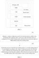
- FIG. 1 shows an example of a system structure according to an embodiment of the present invention.
- a physical host may use Linux as an operating system.
- a virtual machine that runs on the physical host may replace dedicated hardware.
- the virtual machine has a data plane (Data Plane, DP), a control plane (Control Plane, CP), and a virtual network interface controller (Virtual Network Interface Controller, VNIC), that is, a virtual network interface card.
- Data Plane, DP data plane
- Control Plane Control Plane
- VNIC Virtual Network Interface Controller
- the DP relates to processing and transmission of user data.
- the CP relates to monitoring and control of a PMD in the VM.
- FIG. 2 For a specific structure, refer to FIG. 2 .
- the virtual network interface card cannot directly perform data communication with a network device other than the physical host like a network interface controller (Network Interface Controller, NIC), that is, a physical network interface card. Therefore, there is a virtual data channel between the physical network interface card and the virtual network interface card. Then, the virtual network interface card performs data communication with a network device other than the physical host by using the physical network interface card.
- the data channel may be obtained by using
- NIC Network Interface Controller
- NIC Network Interface Controller
- a hardware virtualization technology such as single-root I/O virtualization (Single Root I/O Virtualization, SR-IOV).
- An application Application, APP
- PMD Poll Mode Drivers
- the system structure shown in FIG. 1 mainly includes two parts: the physical host that runs a host operating system and the virtual machine VM that runs a guest operating system.
- the physical host includes a physical network interface card NIC and SR-IOV Alternatively, the SR-IOV may be on a VM side.
- the VM includes an APP, a PMD, and a Linux user space IO driver (Linux User Space I/O Drivers) that are on the DP, user space input/output (Userspace I/O, UIO), and a VNIC.
- the APP and the PMD on the DP belong to user space
- the UIO belongs to kernel space.
- Data packet sending in a PMD mode is as follows: The PMD uses an infinite loop to attempt to receive a data packet from the APP, process the received data packet, and send the processed data packet. The data packet sent by the PMD is sent to the VNIC, and then is sent by the VNIC to the NIC by using the SR-IOV. The NIC sends the data packet to a network device other than the physical host.
- a shared-memory manner may be used, and is specifically as follows:
- the APP stores, into a shared memory, a data packet that needs to be sent, and then information about an address of the data packet in the shared memory, such as a pointer to a storage address of the data packet in the shared memory, is transmitted from the PMD to the NIC.
- a data packet is transparently transmitted between the physical host and the virtual machine, with a relatively few times of OS scheduling.
- the data packet does not need to be copied during transmission from the physical network interface card to the user-mode APP.
- the user-mode APP receives a data packet without requiring a system to call a kernel.
- the PMD mode also has some advantages. For example, the PMD mode substantially has no power consumption and procedure control, and therefore is easy to implement. Based on the foregoing description, it can be learned that during PMD infinite loop execution, a data packet may be equivalently replaced with information about an address of the data packet in a shared memory.
- this embodiment of the present invention provides a more refined power consumption management solution, so as to reduce the power consumption of the processor by using the control plane when the APP receives a relatively small quantity of data packets (that is, when data traffic is relatively small).
- a manner of reducing the power consumption of the processor may include: reducing a primary frequency of the processor, or enabling the processor to be in a non-working state at some times.
- the primary frequency of the processor may be reduced by means of configuring the primary frequency of the processor, reducing a voltage of the processor, or the like.
- a specific manner is determined according to a primary frequency reduction implementation supported by the processor.
- the enabling the processor to be in a non-working state at some times may be specifically: enabling the processor to intermittently sleep or intermittently stop execution of the infinite loop.
- enabling the processor to intermittently sleep or intermittently stop execution of the infinite loop there may be different sleep choices in different application scenarios. For example, in an application scenario of a single-core processor, the entire processor may sleep. In an application scenario in which a processor has multiple cores or many cores, all of the cores of the processor may sleep, or some of the cores of the processor may sleep. The power consumption of the processor is reduced mainly in the latter manner in this embodiment of the present invention.
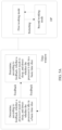
- an embodiment of the present invention provides a scheduling method that is applied to an electronic device. As shown in FIG. 2 , the method specifically includes the following steps.
- higher power consumption of the processor indicates a larger volume of data that can be processed in a unit time. Power consumption is relatively high in a first working mode, and power consumption is relatively low in a second working mode.
- first working mode and the “second working mode” that are used in this embodiment of the present invention are merely intended for distinguishing between the two working modes of the processor, and it should not be understood that the working modes can be classified into only two working modes.
- processing data in a PMD manner is a technical means of using a poll manner to drive an electronic device to process data.
- a feature of the technical means is executing an infinite loop to attempt to receive a data packet or query whether there is data that needs to be processed. Consequently, the processor is always in a state of running at full load.
- a technical solution in this embodiment of the present invention may be applied to a VM and a hardware entity device. Therefore, the processor in this embodiment of the present invention should not be limited only to a physical processor of the electronic device, but should be further extended to a data processing resource allocated to a virtual machine. Corresponding to the VM, theoretically, in the second working mode, data processing resources allocated to the VM may be reduced, or the VM may occupy fewer allocated data processing resources.
- the processed data may be a received data packet.
- the volume of data may be measured by using a quantity of received data packets.
- data traffic may be obtained by means of calculation by using the volume of data. In this case, this step may be more specifically: monitoring the data traffic received by the electronic device, where the processor of the electronic device is configured to be in the first working mode, and the processor receives a data packet in the PMD manner in the first working mode.
- the data traffic is a volume of data actually received in a unit time.
- the volume of data may be measured by using data of data packets, and therefore herein may be a ratio of a quantity of data packets received within the first monitoring time segment to duration of the first monitoring time segment.
- first and second are used to distinguish between technical names, and do not represent other technical meanings.
- the "first working mode” and the “second working mode” represent two different working modes of the processor. Compared with the first working mode, a sleep time is added in the second working mode.
- a “first threshold” and a “second threshold” represent two different data traffic thresholds, and are used to distinguish between a threshold at which the processor needs to be switched to an energy saving mode and a threshold at which the processor needs to be switched to a performance mode.
- this step may be more specifically: switching the processor from the first working mode to the second working mode if it is determined, by means of monitoring, that the data traffic of the electronic device within the first monitoring time segment is less than or equal to a first threshold.
- the volume of data processed by the electronic device is monitored in a periodic monitoring manner. Therefore, the first monitoring time segment may be a periodic monitoring time period, and monitoring periods are equal in time.
- duration of the first monitoring time segment is a fixed value, for example, one time period, this embodiment may be specifically as follows: A quantity of data packets received by the electronic device within the first monitoring time segment is monitored when the processor of the electronic device is in the first working mode; and the processor is switched from the first working mode to the second working mode if it is determined, by means of monitoring, that the quantity of data packets received by the electronic device within the first monitoring time segment is less than or equal to a predetermined threshold. It can be learned that, if the first monitoring time segment is a fixed value, using the volume of data as a measurement criterion and using the data traffic as a measurement criterion have a same technical effect and are equivalent.
- the first threshold may be a specified value used to measure a size of data traffic. Different processors differ in a data packet receiving speed, and therefore differ in data traffic that can be borne.
- the first threshold is a threshold used to determine whether the processor is relatively idle. Therefore, the threshold may be set according to experience. Alternatively, a better specific value of the first threshold may be determined after an actual test is performed based on this embodiment of the present invention. A specific value is not uniquely limited in this embodiment of the present invention.
- This embodiment of the present invention may be executed by the electronic device.
- the electronic device may be the physical host described in the foregoing embodiment, for example, a server or a terminal host; or may be any other electronic device that processes data in the PMD manner. If this embodiment is applied to the field of NFV technologies, and if a VM processes data in the PMD manner, the electronic device may be an electronic device that provides a hardware resource for the VM. A specific representation form of the electronic device is not uniquely limited in this embodiment of the present invention.
- the two working modes are provided for the processor of the electronic device. Power consumption is relatively high in the first working mode, and power consumption is relatively low in the second working mode.
- the volume of data processed by the processor is monitored, so that when a relatively small volume of data is actually processed, energy consumption can be reduced by using a working mode with relatively low energy consumption.
- the PMD manner and the sleep manner are alternately used to process data.
- An alternate manner may be random.
- the sleep time is added in the second working mode, and therefore an energy saving effect can be achieved.
- This embodiment of the present invention further provides a specific manner of alternately processing data.
- the specific manner is as follows: The processor uses the second working mode within a first basic time slice. That the processor processes data in the PMD manner and a sleep manner in the second working mode includes:
- the time segment may include multiple first basic time segments, and each basic time segment may be relatively long, or may be relatively short.
- the first basic time slice is divided into the first time segment and the second time segment to control the working modes.
- that the processor works means that the processor processes data in the PMD manner. That the processor processes data in the PMD manner does not indicate that data is necessarily processed. Whether data is processed depends on whether there is actually data that needs to be processed. That the processor sleeps means that the processor does not process data, that is, when the processor sleeps, regardless of whether there is data that needs to be processed, the processor does not perform an operation of processing data in the PMD manner.
- this embodiment of the present invention further provides a specific implementation solution for increasing working mode control flexibility.
- the solution is specifically as follows: After the first basic time slice for the processor ends, the method further includes: determining, by the processor, a busy/idle state of the processor within the first basic time slice; and when the busy/idle state of the processor within the first basic time slice is a busy state, working, by the processor, within a first time segment of a second basic time slice.
- the busy state means that a volume of received and processed data is greater than a threshold, and has the following representation forms:
- the processor is relatively busy, an actual load ratio is relatively high in this case, and data traffic is relatively large.
- the idle state has the following representation forms: The processor is relatively idle, an actual load ratio is relatively small in this case, and data traffic is relatively small.
- received data traffic may be less than another threshold when the processor sleeps or when the processor is in a working state.
- whether the processor works within the first time segment depends on a current busy/idle state of the processor.
- a data processing capability of the processor is dynamically adjusted on the premise that a working mode of the processor is not switched, so that the data processing capability of the processor can match an actual requirement to improve a speed of responding to a data processing requirement, and working mode switching of the processor due to a sudden change in an instantaneous data processing requirement can be avoided.
- the present invention further provides an implementation solution for controlling the working mode of the processor within the second time segment of the basic time slice.
- the solution is specifically as follows: That the processor works within the second time segment includes: if the processor completes data processing before the second time segment of the first basic time slice ends, ending, by the processor, the second time segment of the first basic time slice in advance, or sleeping in a remaining time of the second time segment.
- the processor may not always need to process data within the second time segment, and therefore no data may need to be processed by the processor for a relatively long time within the second time segment. Therefore, by means of this embodiment, the sleep time may be further increased based on an actual data processing requirement, to further reduce power consumption of the processor.
- the basic time slice may be preferably set to be relatively short. If a manner of "ending the second time of the first basic time slice in advance" is used, the second time segment may be set to be relatively long, or may be set to be relatively short. If a manner of "sleeping in the remaining time of the second time segment" is used, preferably, both the first time segment and the second time segment are set to be relatively short, to improve a speed of responding to a data packet receiving requirement.
- This embodiment further provides a specific implementation solution for determining the busy/idle state of the processor within the first basic time slice based on a specific application scenario of this embodiment of the present invention.
- the solution is as follows:
- the determining, by the processor, a busy/idle state of the processor within the first basic time slice includes:
- both the first threshold and the second threshold are thresholds used to determine whether the processor is busy within the first basic time slice.
- a time consumed to process data is used as a reference for the first threshold, and a longer time consumed to process data indicates that the processor is busier.
- a volume of data is used as a reference for the second threshold, and a larger volume of data indicates that the processor is busier.
- a value that is specifically used is not uniquely limited in this embodiment of the present invention.
- This embodiment further provides a specific implementation solution for determining the busy/idle state of the processor within the first basic time slice based on a specific application scenario of this embodiment of the present invention.
- the solution is as follows: The method further includes:
- both the third threshold and the fourth threshold are thresholds used to determine whether the processor is busy within the first basic time slice.
- a time consumed to process data is used as a reference for the third threshold, and a longer time consumed to process data indicates that the processor is busier.
- a volume of data is used as a reference for the fourth threshold, and a larger volume of data indicates that the processor is busier.
- a value that is specifically used is not uniquely limited in this embodiment of the present invention.
- this embodiment of the present invention further provides a specific implementation solution for switching from the second working mode back to the first working mode.
- the solution is as follows: The method further includes:
- Data traffic is still used as an example.
- the data traffic is used as a criterion for measuring whether the processor is idle.
- This embodiment may be specifically: When the processor is in the second working mode, data traffic of the electronic device within the second monitoring time segment is monitored; and the processor is switched from the second working mode to the first working mode if it is determined, by means of monitoring, that the data traffic of the electronic device within the second monitoring time segment is greater than or equal to the second threshold, where the first threshold is greater than or equal to the second threshold.
- the second threshold is used to determine that the processor is relatively busy or a relatively large quantity of data packets currently need to be received, an application scenario in which the processor exerts a maximum data packet receiving capability of the processor to a greatest extent is needed. That the second threshold is greater than the first threshold may be used as a preferred implementation solution.
- a current working mode may be maintained, that is, is not switched. In this way, when the actual data traffic changes around the first threshold and the second threshold, the processor can be prevented from being frequently switched between the first working mode and the second working mode.
- both the "first monitoring time segment" and the “second monitoring time segment” that is subsequently mentioned are time segment concepts, and both the two monitoring time segments may be time periods. Different periods may be used for the two monitoring time segments. Therefore, the first monitoring time segment and the second monitoring time segment may be different or may be the same. This is not uniquely limited in this embodiment of the present invention. A shorter monitoring time segment leads to more sensitive switching and a faster response speed. A longer monitoring time segment may lead to reduction in switching frequency.
- the solution in this embodiment of the present invention may be applied to a virtual device.
- the virtual device there is a relatively large quantity of requirements for receiving a data packet by using a poll mode driver.
- software uses an infinite-loop manner to attempt to receive/send a data packet.
- the electronic device is the virtual device, and the data processing is data packet receiving and/or data packet sending.
- An embodiment describes more details about a second working mode by using an example.
- data processing is data packet receiving.
- Data traffic is used as a reference for measuring whether a processor is busy.
- the data traffic is a quantity of data packets received in a unit time.
- a first monitoring time segment is defined as a time window, each time window includes multiple basic time slices, and each basic time slice includes a first time segment for sleeping and a second time segment for attempting to perform scheduling.
- This embodiment of the present invention may include the following three parts.
- Part 1 By default, a first working mode is used to receive a data packet on a data plane DP, to maintain high data packet receiving performance of a VM.
- a volume of data actually processed on the data plane DP within a timing period is monitored, and a busy/idle state of the data plane DP within the customized period is marked. If it is detected, by means of monitoring, that all states of the data plane DP within N consecutive timing periods are idle states, a packet receiving model of the DP is switched to the second working mode. Otherwise, the data plane DP is still in the first working mode.
- N may be randomly set. A larger N leads to a smaller quantity of switching times. A smaller N leads to more refined energy consumption control.
- a relatively balanced N may be determined after an actual test is performed. In this embodiment, because a time of the timing period is fixed, a data processing capability of the processor within a timing period, that is, maximum data traffic that the processor can bear, is fixed.
- data traffic that actually occurs within the timing period may be equivalent to a quantity of data packets actually processed within the period, for example, a quantity of received data packets or a quantity of sent data packets.
- FIG. 3 A specific procedure is shown in FIG. 3 , and includes the following steps.
- a control plane CP starts a timer; and when the timer expires, restarts the timer and performs step 302.
- step 303 Determine, by means of statistics collection, whether all busy/idle states within N consecutive timing periods are idle states; and if yes, control the data plane DP to be switched from the first working mode to a second working mode, and continue to perform step 301.
- step 303 there is another case: If busy/idle states of the data plane DP within M consecutive timing periods are all busy states, the data plane DP is controlled to be switched from the second working mode to the first working mode.
- FIG. 4 a more underlying implementation solution is shown in FIG. 4 .
- a control plane CP starts a timer, and then starts to perform the following steps.
- the control plane CP obtains, from the data plane DP, a quantity of packets received on the data plane DP within a timing period in which the timer expires this time.
- step 403. Determine whether the volume of actually processed data is less than a threshold; and if no, go to step 404; or if yes, go to step 405.
- step 404 Reset a count of times the data plane DP is in an idle state, and go to step 401.
- the data plane DP still stays in the first working mode.
- the control plane CP instructs the data plane DP to switch from the first working mode to the second working mode.
- Part 2 Because maximum data traffic that a VNIC can bear in the first working mode is fixed, a quantity of data packets that can be processed within a time is also fixed. Based on this premise, in the second working mode, there may be the following scheduling implementation solution:
- a scheduling process within a second 500 us basic time slice and subsequent 500 us basic time slices is as follows: First, it is determined whether a busy/idle state of the processor within a previous basic time slice is an idle state. If the busy/idle state of the processor within the previous basic time slice is an idle state, the processor sleeps for 100 us, and then attempts to receive a data packet in the first working mode. If the busy/idle state of the processor within the previous basic time slice is a busy state, the processor may directly attempt to receive a data packet in the first working mode, without sleeping.
- a busy/idle state of the processor within a basic time slice may be determined by using a time consumed by the processor to process data. Details may be as follows: It is determined whether a time for attempting to receive a data packet in the first working mode reaches 400 us or 300 us, and the time may be set. If yes, it is determined that the busy/idle state of the processor within the basic time slice is a busy state. Otherwise, the busy/idle state of the processor within the basic time slice is an idle state. Alternatively, a busy/idle state of the processor within a basic time slice may be determined by using an actual load ratio of the processor within the basic time slice.
- a maximum quantity of data packets received by the processor within 400 us in the first working mode can be determined, and therefore a specified ratio is used. For example, it is determined that the busy/idle state of the processor within the basic time slice is a busy state if a quantity of actually received data packets reaches 80% of the maximum quantity; or it is determined that the busy/idle state of the processor within the basic time slice is an idle state if a quantity of actually received data packets is less than 60% of the maximum quantity.
- a specific reference criterion may be set. Alternatively, a relatively proper reference criterion may be determined by using an actual test.
- a scheduling manner for the second basic time slice may be used within all subsequent basic time slices. Because the time of the basic time slice is relatively short, when load is relatively small, the sleep time is relatively long; or when load is relatively large, the sleep time is relatively short. In this case, from a macroscopic perspective, a load ratio of the processor on the data plane DP and the volume of actually processed data are in a linear relationship, so that the load ratio of the processor can be precisely controlled.
- a time window includes basic time slices. Within each basic time slice, "determining, according to feedback, whether the processor needs to sleep, and detecting whether the processor is in an idle state within the basic time slice" and “feedback" are performed. Feedback content is whether the processor is in an idle state within the basic time slice.
- FIG. 6A and FIG. 6B An energy efficiency management function is enabled. After starting a timer, the control plane CP starts to perform the following steps.
- T1 is less than 400 us, this step ends after data packet receiving is completed.
- T1 is equal to 400 us, because the basic time slice runs out, T1 ends when reaching 400 us. In this case, data packet receiving may have been completed or may not have been completed. Therefore, T1 herein should be less than or equal to 400 us.
- the proportion of a sleep time or an actual data packet receiving time in a time of one basic time slice is used.
- the proportion may also be used to indicate an actual load ratio of the processor, that is, a larger proportion of a sleep time in a time of one basic time slice indicates a lower actual load ratio.
- step 605. Determine whether the processor is in an idle state within a previous basic time slice; and if yes, go to step 606; otherwise, go to step 607.
- T2 is less than 400 us, this step ends after data packet receiving is completed.
- T2 is equal to 400 us, because the basic time slice runs out, T2 ends when reaching 400 us. In this case, data packet receiving may have been completed or may not have been completed. Therefore, T2 herein should be less than or equal to 400 us.
- step 608. Determine, by means of calculation according to the proportion of a sleep time or an actual data packet receiving time in a time of one basic time slice, whether the processor is in an idle state within a current basic time slice; and if yes, go to step 609; or if no, go to step 610.
- step 611 Mark that the processor is in a busy state within the current basic time slice, and enter step 611.
- step 611 Determine whether the 10 ms time window ends; and if no, go to step 605; or if yes, go to step 612.
- step 612. Determine whether a load ratio of the processor within the 10 ms time window is less than a threshold; and if yes, go to step 601; or if no, go to step 613.
- a time window is changed to basic time slices with a smaller granularity.
- the processor sleeps within a current basic time slice if the processor is in an idle state within a previous basic time slice.
- a relatively small volume of data is actually processed, a short time is consumed to receive/send a data packet, and the processor has a relatively large quantity of opportunities to sleep within a basic time slice.
- the processor has a relatively small quantity of opportunities to sleep within a basic time slice.
- power of the processor is substantially in direct proportion to the volume of actually processed data.
- a system is scaled up/down (scale up/down).
- the processor sleeps for a quite short time within each basic time slice, a relatively small delay in responding to service processing can be ensured.
- Part 3 Based on the implementation in Part 2, this part provides an implementation solution for switching from the first working mode to the second working mode.
- step 701 is performed within each basic time slice: Determine, by means of calculation, a busy/idle state of the processor within the basic time slice.
- a volume of data actually processed by the processor in the second working mode within a time of the basic time slice is obtained from the data plane DP, and then it is determined, according to the volume of actually processed data, whether the processor is in a busy state or in an idle state within the basic time slice.
- step 702 Determine, by means of statistics collection, a busy/idle state of the processor within the time window.
- the data plane DP is controlled to be switched from the second working mode to the first working mode. It may be understood that, if the data plane DP is currently in the first working mode, and if the processor is in an idle state within the time window, the data plane DP is controlled to be switched from the first working mode to the second working mode.
- FIG. 5B If the data plane DP controls the processor to be switched from the second working mode back to the first working mode or from the first working mode to the second working mode, refer to FIG. 5B .
- a difference lies in that a time window control part is set on the data plane DP.
- FIG. 5B For descriptions of FIG. 5B , refer to the text descriptions corresponding to FIG. 5A . Details are not described herein again.
- FIG. 8 is a diagram of a result obtained after an actual test.
- An x-axis is the volume of actually processed data
- a y-axis is the utilization of the processor.
- the utilization of the processor is corresponding to corresponding power consumption, and therefore the power consumption of the processor is also in a linear relationship with the volume of actually processed data on the whole.
- An embodiment of the present invention further provides an electronic device.
- the electronic device includes: a data volume detection unit 901, a switching control unit 902, and a processing unit 903.
- the data volume detection unit 901 is configured to monitor a volume of data processed by the electronic device within a first monitoring time segment.
- the switching control unit 902 is configured to switch the processing unit 903 from the first working mode to a second working mode if it is determined, according to the volume of data processed by the electronic device within the first monitoring time segment, that the processing unit 903 is idle within the first monitoring time segment.
- the processing unit 903 is configured to: process, by the processing unit 903, data in a PMD manner in the first working mode when the processing unit 903 is configured to be in the first working mode; and process, by the processing unit 903, data in the PMD manner and a sleep manner in the second working mode.
- the two working modes are provided for the processing unit 903 of the electronic device. Power consumption is relatively high in the first working mode, and power consumption is relatively low in the second working mode.
- the volume of data processed by the processing unit 903 is monitored, so that when a relatively small volume of data is actually processed, energy consumption can be reduced by using a working mode with relatively low energy consumption.
- the processing unit 903 is specifically configured to use the second working mode within a first basic time slice in the second working mode.
- the first basic time slice includes a first time segment and a second time segment.
- the processing unit 903 sleeps within the first time segment, and works within the second time segment.
- the processing unit 903 further includes:
- the processing unit 903 is specifically configured to: if the processing unit 903 completes data processing before the second time segment of the first basic time slice ends, end the second time segment of the first basic time slice in advance, or sleep in a remaining time of the second time segment.
- the busy/idle determining unit 1001 is specifically configured to: if a time in which the processing unit 903 processes data within the first basic time slice is greater than a first threshold, determine, by the electronic device, that the busy/idle state within the first basic time slice is a busy state; or
- the busy/idle determining unit 1001 is further configured to: if a time in which the processing unit 903 processes data within the first basic time slice is less than the third threshold, determine that the busy/idle state within the first basic time slice is an idle state, where the third threshold is less than or equal to the first threshold; or
- the data volume detection unit 901 is further configured to: when the processing unit 903 is in the second working mode, monitor a volume of data processed by the electronic device within a second monitoring time segment.
- the switching control unit 902 is further configured to switch the processing unit 903 from the second working mode to the first working mode if it is determined, according to the volume of data processed by the electronic device within the second monitoring time segment, that the processing unit 903 is busy within the second monitoring time segment.
- Data traffic is still used as an example.
- the data traffic is used as a criterion for measuring whether the processing unit 903 is idle.
- This embodiment may be specifically:
- the switching control unit 902 is further configured to switch the processing unit 903 from the second working mode to the first working mode if it is determined, by means of monitoring, that data traffic of the electronic device within the second monitoring time segment is greater than or equal to the second threshold, where the first threshold is greater than or equal to the second threshold.
- An embodiment of the present invention further provides another electronic device.
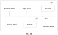
- the electronic device includes a processor 1101 and a memory 1102.
- the electronic device may further include a receiving device, a sending device, an output device, and the like.
- the processor 1101 and the memory 1102 may be connected by using a bus 1103, or may be connected by using another hardware interface.
- the processor 1101 has the following functions: monitoring a volume of data processed by the electronic device within a first monitoring time segment, where the processor 1101 of the electronic device is configured to be in a first working mode, and the processor 1101 processes data in a PMD manner in the first working mode; and switching the processor 1101 from the first working mode to a second working mode if it is determined, according to the volume of data processed by the electronic device within the first monitoring time segment, that the processor is idle within the first monitoring time segment, where the processor 1101 processes data in the PMD manner and a sleep manner in the second working mode.
- a sleep time is added in the second working mode. Therefore, power consumption is relatively low, and correspondingly a data packet receiving capability is relatively low.
- Data packet receiving and/or sending is used as an example. The manner may be: If it is determined, by means of monitoring, that data traffic of the electronic device within the first monitoring time segment is less than or equal to a first threshold, it is determined that the processor is idle within the first monitoring time segment, where the first threshold is a threshold corresponding to the data traffic that is a volume of data received in a unit time.
- the manner may be: If it is determined, by means of monitoring, that the volume of data processed by the electronic device within the first monitoring time segment is less than or equal to a first threshold, it is determined that the processor is idle within the first monitoring time segment, where the first threshold is a threshold corresponding to the volume of data processed within the first monitoring time segment.
- the first threshold is a threshold used to determine whether the processor is relatively idle. When the processor is relatively idle, the processor is switched to a working mode with relatively low energy consumption.
- the processor 1101 uses the second working mode within a first basic time slice, and that the processor 1101 processes data in the PMD manner and a sleep manner in the second working mode includes:
- the first basic time slice and a second basic time slice in a subsequent embodiment are obtained after basic time slices are classified.
- the first basic time slice may be a first basic time slice that exists after the processor 1101 is switched from the first working mode to the second working mode.
- the processor 1101 works, by default in each basic time slice, in a working mode within the first basic time slice.
- the second working mode may be a representative of another basic time slice other than the first basic time slice.
- the first basic time slice may be considered as a previous basic time slice of the second basic time slice.
- Duration of a basic time slice may be randomly set, and usually may be set to be relatively short.
- the first time segment and the second time segment may be correspondingly relatively short. In this way, scheduling precision can be improved.
- the processor 1101 sleeps for a relatively short time each time, so that a response speed of the processor 1101 can be improved.
- the processor 1101 has the following functions: After the first basic time slice ends, determining, by the processor 1101, a busy/idle state of the processor 1101 within the first basic time slice; and when the busy/idle state of the processor 1101 within the first basic time slice is a busy state, working, by the processor 1101, within a first time segment of a second basic time slice.
- whether the processor 1101 works within the first time segment depends on a current busy/idle state of the processor 1101.
- a data processing capability of the processor 1101 may be dynamically adjusted on the premise that a working mode of the processor 1101 is not switched, so that the data processing capability of the processor 1101 can match an actual requirement to improve a speed of responding to a data processing requirement, energy consumption is in a linear positive correlation with an actual data processing requirement, and working mode switching of the processor 1101 due to a sudden change in an instantaneous data processing requirement can be avoided.
- That the processor 1101 works within the second time segment includes: if the processor 1101 completes data processing before the second time segment of the first basic time slice ends, ending, by the processor 1101, the second time segment of the first basic time slice in advance, or sleeping in a remaining time of the second time segment.
- the processor 1101 may not always need to process data within the second time segment, and therefore no data may need to be processed by the processor 1101 for a relatively long time within the second time segment.
- the sleep time may be further increased based on an actual data processing requirement, to further reduce power consumption of the processor 1101.
- the determining, by the processor 1101, a busy/idle state of the processor 1101 within the first basic time slice includes:
- both the first threshold and the second threshold are thresholds used to determine whether the processor 1101 is busy within the first basic time slice.
- a time consumed to process data is used as a reference for the first threshold, and a longer time consumed to process data indicates that the processor 1101 is busier.
- a volume of data is used as a reference for the second threshold, and a larger volume of data indicates that the processor 1101 is busier.
- a value that is specifically used is not uniquely limited in this embodiment of the present invention.
- processor 1101 is further configured to determine the busy/idle state is specifically as follows:
- both the third threshold and the fourth threshold are thresholds used to determine whether the processor 1101 is busy within the first basic time slice.
- a time consumed to process data is used as a reference for the third threshold, and a longer time consumed to process data indicates that the processor 1101 is busier.
- a volume of data is used as a reference for the fourth threshold, and a larger volume of data indicates that the processor 1101 is busier.
- a value that is specifically used is not uniquely limited in this embodiment of the present invention.
- the processor 1101 is further configured to: when the processor 1101 is in the second working mode, monitor a volume of data processed by the electronic device within a second monitoring time segment; and switch the processor from the second working mode to the first working mode if it is determined, according to the volume of data processed by the electronic device within the second monitoring time segment, that the processor is busy within the second monitoring time segment.
- the first threshold is greater than or equal to the second threshold.
- Data traffic is still used as an example.
- the data traffic is used as a criterion for measuring whether the processor is idle.
- This embodiment may be specifically: When the processor 1101 is in the second working mode, data traffic of the electronic device within the second monitoring time segment is monitored; and the processor 1101 is switched from the second working mode to the first working mode if it is determined, currently need to be processed, an application scenario in which the processor exerts a maximum data processing capability of the processor to a greatest extent is needed. That the second threshold is greater than the first threshold may be used as a preferred implementation solution.
- a current working mode may be maintained, so that when actual data traffic changes around the first threshold and the second threshold, the processor 1101 is prevented from being frequently switched between the first working mode and the second working mode.
- the electronic device is a virtual device. If the electronic device is a virtual device, a hardware entity to which the electronic device in this embodiment of the present invention is applied may be corresponding to the physical host shown in FIG. 1 , and the electronic device is corresponding to the virtual machine.
- the processor may be a processor of the physical host, or may be a data processing resource allocated by the physical host to the virtual machine.
- the apparatus division is merely logical function division, but is not limited to the foregoing division provided that corresponding functions can be implemented.
- specific names of the functional units are merely provided for the purpose of distinguishing the units from one another, but are not intended to limit the protection scope of the present invention.
- the corresponding program may be stored in a computer readable storage medium.
- the mentioned storage medium may be a read-only memory, a magnetic disk, an optical disc, or the like.
Landscapes
- Engineering & Computer Science (AREA)
- Theoretical Computer Science (AREA)
- General Engineering & Computer Science (AREA)
- Physics & Mathematics (AREA)
- General Physics & Mathematics (AREA)
- Quality & Reliability (AREA)
- Software Systems (AREA)
- Computing Systems (AREA)
- Computer Hardware Design (AREA)
- Mathematical Physics (AREA)
- Power Sources (AREA)
- Mobile Radio Communication Systems (AREA)
Claims (8)
- Planungsverfahren, das auf eine elektronische Vorrichtung angewendet wird und umfasst:Überwachen (201) einer von der elektronischen Vorrichtung verarbeiteten Datenmenge innerhalb eines ersten Überwachungszeitsegments, wobei ein Prozessor der elektronischen Vorrichtung dafür ausgelegt ist, sich in einem ersten Arbeitsmodus zu befinden, und der Prozessor im ersten Arbeitsmodus Daten nach Art eines Polling-Modus-Treibers, PMD ("Poll Mode Driver"), verarbeitet; undUmschalten (202) des Prozessors vom ersten Arbeitsmodus in einen zweiten Arbeitsmodus, wenn gemäß der von der elektronischen Vorrichtung innerhalb des ersten Überwachungszeitsegments verarbeiteten Datenmenge bestimmt wird, dass der Prozessor innerhalb des ersten Überwachungszeitsegments inaktiv ist, wobei der Prozessor im zweiten Arbeitsmodus Daten nach der Art eines PMD und in einer Schlaf-Art verarbeitet;wobei der Prozessor den zweiten Arbeitsmodus innerhalb einer ersten Basiszeitscheibe verwendet, die ein erstes Zeitsegment und ein zweites Zeitsegment umfasst, undder Prozessor innerhalb des ersten Zeitsegments schläft; und innerhalb des zweiten Zeitsegments Daten verarbeitet, gekennzeichnet durch:
wenn der Prozessor die Datenverarbeitung abschließt, bevor das zweite Zeitsegment der ersten Basiszeitscheibe endet, vorzeitiges Beenden, durch den Prozessor, des zweiten Zeitsegments der ersten Basiszeitscheibe oder Schlafen während einer Restzeit des zweiten Zeitsegments. - Verfahren gemäß Anspruch 1, wobei das Verfahren nach dem Ende der ersten Basiszeitscheibe ferner umfasst:
Bestimmen, durch den Prozessor, eines Belegt-/Inaktivzustands des Prozessors innerhalb der ersten Basiszeitscheibe; und wenn der Belegt-/Inaktivzustand des Prozessors innerhalb der ersten Basiszeitscheibe ein Belegtzustand ist, Arbeiten, durch den Prozessor, innerhalb eines ersten Zeitsegments einer zweiten Basiszeitscheibe. - Verfahren gemäß Anspruch 1 oder 2, wobei das Bestimmen, durch den Prozessor, eines Belegt-/Inaktivzustands des Prozessors innerhalb der ersten Basiszeitscheibe umfasst:wenn eine Zeit, in der der Prozessor Daten innerhalb der ersten Basiszeitscheibe verarbeitet, länger als ein erster Schwellenwert ist, Bestimmen, durch die elektronische Vorrichtung, dass der Belegt-/Inaktivzustand des Prozessors innerhalb der ersten Basiszeitscheibe ein Belegtzustand ist; oderwenn sich der Prozessor in einem Datenverarbeitungszustand befindet, wenn das zweite Zeitsegment der ersten Basiszeitscheibe endet, Bestimmen, durch die elektronische Vorrichtung, dass der Belegt-/Inaktivzustand des Prozessors innerhalb der ersten Basiszeitscheibe ein Belegtzustand ist; oderwenn eine vom Prozessor innerhalb der ersten Basiszeitscheibe verarbeitete Datenmenge größer als ein zweiter Schwellenwert ist, Bestimmen, durch die elektronische Vorrichtung, dass der Belegt-/Inaktivzustand des Prozessors innerhalb der ersten Basiszeitscheibe ein Belegtzustand ist.
- Verfahren gemäß einem der Ansprüche 1 bis 3, wobei das Verfahren ferner umfasst:wenn sich der Prozessor im zweiten Arbeitsmodus befindet, Überwachen einer von der elektronischen Vorrichtung innerhalb eines zweiten Überwachungszeitsegments verarbeiteten Datenmenge; undUmschalten des Prozessors vom zweiten Arbeitsmodus in den ersten Arbeitsmodus, wenn gemäß der von der elektronischen Vorrichtung innerhalb des zweiten Überwachungszeitsegments verarbeiteten Datenmenge bestimmt wird, dass der Prozessor innerhalb des zweiten Überwachungszeitsegments belegt ist.
- Elektronische Vorrichtung, die ausgelegt ist zum:Überwachen einer von der elektronischen Vorrichtung innerhalb eines ersten Überwachungszeitsegments verarbeiteten Datenmenge;Umschalten eines Prozessors von einem ersten Arbeitsmodus in einen zweiten Arbeitsmodus, wenn gemäß der von der elektronischen Vorrichtung innerhalb des ersten Überwachungszeitsegments verarbeiteten Datenmenge bestimmt wird, dass der Prozessor innerhalb des ersten Überwachungszeitsegments inaktiv ist; undVerarbeiten von Daten nach Art eines Polling-Modus-Treibers, PMD ("Poll Mode Driver") im ersten Arbeitsmodus; und Verarbeiten von Daten nach der Art eines PMD und in einer Schlaf-Art im zweiten Arbeitsmodus;Verwenden des zweiten Arbeitsmodus innerhalb einer ersten Basiszeitscheibe, die ein erstes Zeitsegment und ein zweites Zeitsegment umfasst, und wobeider Prozessor innerhalb des ersten Zeitsegments schläft und innerhalb des zweiten Zeitsegments Daten verarbeitet, gekennzeichnet durch:
wenn der Prozessor die Datenverarbeitung abschließt, bevor das zweite Zeitsegment der ersten Basiszeitscheibe endet, vorzeitiges Beenden des zweiten Zeitsegments der ersten Basiszeitscheibe oder Schlafen während einer Restzeit des zweiten Zeitsegments. - Elektronische Vorrichtung gemäß Anspruch 5, die ferner ausgelegt ist zum:Bestimmen eines Belegt-/Inaktivzustands des Prozessors innerhalb der ersten Basiszeitscheibe, nachdem die erste Basiszeitscheibe endet; undwenn der Belegt-/Inaktivzustand des Prozessors innerhalb der ersten Basiszeitscheibe ein Belegtzustand ist, Steuern des Prozessors derart, dass er innerhalb eines ersten Zeitsegments einer zweiten Basiszeitscheibe arbeitet.
- Elektronische Vorrichtung gemäß Anspruch 5 oder 6, die ferner ausgelegt ist zum:wenn eine Zeit, in der der Prozessor Daten innerhalb der ersten Basiszeitscheibe verarbeitet, länger als ein erster Schwellenwert ist, Bestimmen, dass der Belegt-/Inaktivzustand des Prozessors innerhalb der ersten Basiszeitscheibe ein Belegtzustand ist; oderwenn sich der Prozessor in einem Datenverarbeitungszustand befindet, wenn das zweite Zeitsegment der ersten Basiszeitscheibe endet, Bestimmen, dass der Belegt-/Inaktivzustand des Prozessors innerhalb der ersten Basiszeitscheibe ein Belegtzustand ist; oderwenn eine vom Prozessor innerhalb der ersten Basiszeitscheibe verarbeitete Datenmenge größer als ein zweiter Schwellenwert ist, Bestimmen, dass der Belegt-/Inaktivzustand des Prozessors innerhalb der ersten Basiszeitscheibe ein Belegtzustand ist.
- Elektronische Vorrichtung nach einem der Ansprüche 5 bis 7, die ferner ausgelegt ist zum:wenn sich der Prozessor im zweiten Arbeitsmodus befindet, Überwachen einer von der elektronischen Vorrichtung innerhalb eines zweiten Überwachungszeitsegments verarbeiteten Datenmenge; undUmschalten des Prozessors vom zweiten Arbeitsmodus in den ersten Arbeitsmodus, wenn gemäß der von der elektronischen Vorrichtung innerhalb des zweiten Überwachungszeitsegments verarbeiteten Datenmenge bestimmt wird, dass der Prozessor innerhalb des zweiten Überwachungszeitsegments belegt ist.
Applications Claiming Priority (2)
| Application Number | Priority Date | Filing Date | Title |
|---|---|---|---|
| CN201610176197.3A CN105786674B (zh) | 2016-03-24 | 2016-03-24 | 一种调度方法及电子设备 |
| PCT/CN2017/076962 WO2017162096A1 (zh) | 2016-03-24 | 2017-03-16 | 一种调度方法及电子设备 |
Publications (3)
| Publication Number | Publication Date |
|---|---|
| EP3428801A1 EP3428801A1 (de) | 2019-01-16 |
| EP3428801A4 EP3428801A4 (de) | 2019-03-27 |
| EP3428801B1 true EP3428801B1 (de) | 2023-05-03 |
Family
ID=56391973
Family Applications (1)
| Application Number | Title | Priority Date | Filing Date |
|---|---|---|---|
| EP17769373.6A Active EP3428801B1 (de) | 2016-03-24 | 2017-03-16 | Planungsverfahren und elektronische vorrichtung |
Country Status (4)
| Country | Link |
|---|---|
| US (1) | US10929179B2 (de) |
| EP (1) | EP3428801B1 (de) |
| CN (1) | CN105786674B (de) |
| WO (1) | WO2017162096A1 (de) |
Families Citing this family (13)
| Publication number | Priority date | Publication date | Assignee | Title |
|---|---|---|---|---|
| CN105786674B (zh) | 2016-03-24 | 2018-11-16 | 华为技术有限公司 | 一种调度方法及电子设备 |
| CN106527653A (zh) * | 2016-10-12 | 2017-03-22 | 东软集团股份有限公司 | 调整cpu频率的方法及装置 |
| CN110278052B (zh) * | 2018-03-15 | 2020-10-09 | 大唐移动通信设备有限公司 | 一种数据接收方法及装置 |
| CN109086128B (zh) * | 2018-08-28 | 2021-06-18 | 迈普通信技术股份有限公司 | 任务调度方法及装置 |
| CN110968403A (zh) * | 2018-09-28 | 2020-04-07 | 深信服科技股份有限公司 | 一种cpu工作控制方法、装置、设备及存储介质 |
| CN109743207B (zh) * | 2018-12-29 | 2021-09-14 | 联想(北京)有限公司 | 服务器性能调节方法和服务器 |
| US11455024B2 (en) * | 2019-04-10 | 2022-09-27 | Red Hat, Inc. | Idle state estimation by scheduler |
| US10856331B1 (en) * | 2019-09-10 | 2020-12-01 | Cypress Semiconductor Corporation | Devices, systems, and methods for mitigating aggressive medium reservations |
| CN112579513B (zh) * | 2020-12-08 | 2023-04-25 | 成都海光微电子技术有限公司 | 芯片自适应控制电路、方法和系统级芯片 |
| CN112968965B (zh) * | 2021-02-25 | 2022-12-09 | 网宿科技股份有限公司 | Nfv网络节点的元数据服务方法、服务器及存储介质 |
| CN115129462A (zh) * | 2021-03-26 | 2022-09-30 | 炬力(珠海)微电子有限公司 | 处理器负载的确定方法及装置 |
| US20250208686A1 (en) * | 2023-12-22 | 2025-06-26 | Caterpillar Inc. | System and method of entering a low power mode for a battery electric machine |
| US20260050319A1 (en) * | 2024-08-16 | 2026-02-19 | Qualcomm Incorporated | Dynamic power management for data plane applications in user space |
Family Cites Families (15)
| Publication number | Priority date | Publication date | Assignee | Title |
|---|---|---|---|---|
| JP5069472B2 (ja) * | 2004-02-19 | 2012-11-07 | コーニンクレッカ フィリップス エレクトロニクス エヌ ヴィ | 無線医療監視方法及び関連のシステム並びに患者監視装置 |
| US8286169B2 (en) * | 2005-06-17 | 2012-10-09 | Intel Corporation | Dynamic scheduling an interval for polling devices based on a current operational power mode in an extensible firmware interface architecture |
| CN1924761A (zh) * | 2005-08-31 | 2007-03-07 | 松下电器产业株式会社 | 数据处理装置、程序、记录介质和内容回放装置 |
| JP4983033B2 (ja) * | 2006-02-08 | 2012-07-25 | ソニー株式会社 | 通信装置および方法、並びにプログラム |
| US8135346B2 (en) * | 2008-12-04 | 2012-03-13 | Broadcom Corporation | Method and system for a reduced USB polling rate to save power on a Bluetooth host |
| US8509694B2 (en) * | 2010-08-31 | 2013-08-13 | Apple Inc. | Techniques for facilitating communication between a portable media device and an accessory using multiple communication paths |
| US20130031392A1 (en) | 2011-07-29 | 2013-01-31 | Mclane William J | Usb device side wake-up for power conservation and management |
| WO2013019225A1 (en) * | 2011-08-03 | 2013-02-07 | Draeger Medical Systems, Inc. | Throughput-based active mode trigger |
| US9936370B2 (en) * | 2012-12-25 | 2018-04-03 | Lg Electronics Inc. | Scanning method and apparatus in wireless LAN system |
| CN103731364B (zh) | 2014-01-16 | 2017-02-01 | 赛特斯信息科技股份有限公司 | 基于x86平台实现万兆大流量快速收包的方法 |
| CN104469905B (zh) * | 2014-11-14 | 2018-07-13 | 惠州Tcl移动通信有限公司 | 降低nfc芯片闲置时功耗的方法及系统 |
| KR102284467B1 (ko) | 2014-12-22 | 2021-08-03 | 인텔 코포레이션 | 네트워크 디바이스에서의 수신된 패킷의 처리와 연관된 전력 관리 기법 |
| US9961033B2 (en) * | 2015-11-09 | 2018-05-01 | Red Hat Israel, Ltd. | Memory-mapped input/output (I/O) channel |
| WO2017155545A1 (en) * | 2016-03-11 | 2017-09-14 | Tektronix Texas, Llc. | Timestamping data received by monitoring system in nfv |
| CN105786674B (zh) * | 2016-03-24 | 2018-11-16 | 华为技术有限公司 | 一种调度方法及电子设备 |
-
2016
- 2016-03-24 CN CN201610176197.3A patent/CN105786674B/zh active Active
-
2017
- 2017-03-16 EP EP17769373.6A patent/EP3428801B1/de active Active
- 2017-03-16 WO PCT/CN2017/076962 patent/WO2017162096A1/zh not_active Ceased
-
2018
- 2018-09-24 US US16/139,817 patent/US10929179B2/en active Active
Also Published As
| Publication number | Publication date |
|---|---|
| WO2017162096A1 (zh) | 2017-09-28 |
| EP3428801A1 (de) | 2019-01-16 |
| US10929179B2 (en) | 2021-02-23 |
| CN105786674A (zh) | 2016-07-20 |
| EP3428801A4 (de) | 2019-03-27 |
| US20190034229A1 (en) | 2019-01-31 |
| CN105786674B (zh) | 2018-11-16 |
Similar Documents
| Publication | Publication Date | Title |
|---|---|---|
| US10929179B2 (en) | Scheduling method and electronic device | |
| US10628216B2 (en) | I/O request scheduling method and apparatus by adjusting queue depth associated with storage device based on hige or low priority status | |
| EP2513751B1 (de) | System und verfahren zur steuerung der leistung einer zentralen prozessoreinheit in einem virtualisierten system | |
| KR101864980B1 (ko) | 가상 머신 전력 관리 | |
| US10990407B2 (en) | Dynamic interrupt reconfiguration for effective power management | |
| CN101916207B (zh) | 桌面虚拟化环境下的节能方法、装置及系统 | |
| WO2021008543A1 (zh) | 一种资源调度的方法和电子设备 | |
| US8484495B2 (en) | Power management in a multi-processor computer system | |
| WO2016101099A9 (en) | Techniques for power management associated with processing received packets at a network device | |
| CN114710563B (zh) | 一种集群节能方法及装置 | |
| US9489223B2 (en) | Virtual machine wakeup using a memory monitoring instruction | |
| US20120297216A1 (en) | Dynamically selecting active polling or timed waits | |
| US8892819B2 (en) | Multi-core system and external input/output bus control method | |
| US20250190249A1 (en) | Resource scheduling method and apparatus | |
| WO2014142847A1 (en) | Multi-core binary translation task processing | |
| WO2024230309A1 (zh) | 处理器调度方法、装置、计算机设备、计算机可读存储介质及计算机程序产品 | |
| Wu et al. | Toward low CPU usage and efficient DPDK communication in a cluster | |
| EP3646138A1 (de) | Leistungsverwaltung eines ereignisbasierten verarbeitungssystems | |
| US12498964B2 (en) | Server delay control device, server delay control method and program | |
| Fujimoto et al. | Energy-efficient KBP: kernel enhancements for low-latency and energy-efficient networking | |
| Natori et al. | Power saving for hardware accelerated applications with dynamical processor switching | |
| Lee et al. | Fine-grained I/O traffic control middleware for I/O fairness in Virtualized system | |
| JP2012164006A (ja) | クロック周波数制御プログラム、クロック周波数制御装置 | |
| CN121743024A (zh) | 物理机的处理器调度方法、设备、系统、产品及存储介质 | |
| Priescu et al. | Efficient Use of Heterogeneous Multicore Architectures in Reliable Multiserver Systems |
Legal Events
| Date | Code | Title | Description |
|---|---|---|---|
| STAA | Information on the status of an ep patent application or granted ep patent |
Free format text: STATUS: THE INTERNATIONAL PUBLICATION HAS BEEN MADE |
|
| PUAI | Public reference made under article 153(3) epc to a published international application that has entered the european phase |
Free format text: ORIGINAL CODE: 0009012 |
|
| STAA | Information on the status of an ep patent application or granted ep patent |
Free format text: STATUS: REQUEST FOR EXAMINATION WAS MADE |
|
| 17P | Request for examination filed |
Effective date: 20181008 |
|
| AK | Designated contracting states |
Kind code of ref document: A1 Designated state(s): AL AT BE BG CH CY CZ DE DK EE ES FI FR GB GR HR HU IE IS IT LI LT LU LV MC MK MT NL NO PL PT RO RS SE SI SK SM TR |
|
| AX | Request for extension of the european patent |
Extension state: BA ME |
|
| A4 | Supplementary search report drawn up and despatched |
Effective date: 20190225 |
|
| RIC1 | Information provided on ipc code assigned before grant |
Ipc: G06F 11/34 20060101ALI20190219BHEP Ipc: G06F 11/30 20060101AFI20190219BHEP |
|
| DAV | Request for validation of the european patent (deleted) | ||
| DAX | Request for extension of the european patent (deleted) | ||
| STAA | Information on the status of an ep patent application or granted ep patent |
Free format text: STATUS: EXAMINATION IS IN PROGRESS |
|
| 17Q | First examination report despatched |
Effective date: 20210215 |
|
| GRAP | Despatch of communication of intention to grant a patent |
Free format text: ORIGINAL CODE: EPIDOSNIGR1 |
|
| STAA | Information on the status of an ep patent application or granted ep patent |
Free format text: STATUS: GRANT OF PATENT IS INTENDED |
|
| INTG | Intention to grant announced |
Effective date: 20221201 |
|
| GRAS | Grant fee paid |
Free format text: ORIGINAL CODE: EPIDOSNIGR3 |
|
| GRAA | (expected) grant |
Free format text: ORIGINAL CODE: 0009210 |
|
| STAA | Information on the status of an ep patent application or granted ep patent |
Free format text: STATUS: THE PATENT HAS BEEN GRANTED |
|
| AK | Designated contracting states |
Kind code of ref document: B1 Designated state(s): AL AT BE BG CH CY CZ DE DK EE ES FI FR GB GR HR HU IE IS IT LI LT LU LV MC MK MT NL NO PL PT RO RS SE SI SK SM TR |
|
| REG | Reference to a national code |
Ref country code: GB Ref legal event code: FG4D |
|
| REG | Reference to a national code |
Ref country code: DE Ref legal event code: R096 Ref document number: 602017068329 Country of ref document: DE |
|
| REG | Reference to a national code |
Ref country code: AT Ref legal event code: REF Ref document number: 1565246 Country of ref document: AT Kind code of ref document: T Effective date: 20230515 Ref country code: CH Ref legal event code: EP |
|
| REG | Reference to a national code |
Ref country code: IE Ref legal event code: FG4D |
|
| REG | Reference to a national code |
Ref country code: LT Ref legal event code: MG9D |
|
| REG | Reference to a national code |
Ref country code: NL Ref legal event code: MP Effective date: 20230503 |
|
| REG | Reference to a national code |
Ref country code: AT Ref legal event code: MK05 Ref document number: 1565246 Country of ref document: AT Kind code of ref document: T Effective date: 20230503 |
|
| PG25 | Lapsed in a contracting state [announced via postgrant information from national office to epo] |
Ref country code: SE Free format text: LAPSE BECAUSE OF FAILURE TO SUBMIT A TRANSLATION OF THE DESCRIPTION OR TO PAY THE FEE WITHIN THE PRESCRIBED TIME-LIMIT Effective date: 20230503 Ref country code: PT Free format text: LAPSE BECAUSE OF FAILURE TO SUBMIT A TRANSLATION OF THE DESCRIPTION OR TO PAY THE FEE WITHIN THE PRESCRIBED TIME-LIMIT Effective date: 20230904 Ref country code: NO Free format text: LAPSE BECAUSE OF FAILURE TO SUBMIT A TRANSLATION OF THE DESCRIPTION OR TO PAY THE FEE WITHIN THE PRESCRIBED TIME-LIMIT Effective date: 20230803 Ref country code: NL Free format text: LAPSE BECAUSE OF FAILURE TO SUBMIT A TRANSLATION OF THE DESCRIPTION OR TO PAY THE FEE WITHIN THE PRESCRIBED TIME-LIMIT Effective date: 20230503 Ref country code: ES Free format text: LAPSE BECAUSE OF FAILURE TO SUBMIT A TRANSLATION OF THE DESCRIPTION OR TO PAY THE FEE WITHIN THE PRESCRIBED TIME-LIMIT Effective date: 20230503 Ref country code: AT Free format text: LAPSE BECAUSE OF FAILURE TO SUBMIT A TRANSLATION OF THE DESCRIPTION OR TO PAY THE FEE WITHIN THE PRESCRIBED TIME-LIMIT Effective date: 20230503 |
|
| PG25 | Lapsed in a contracting state [announced via postgrant information from national office to epo] |
Ref country code: RS Free format text: LAPSE BECAUSE OF FAILURE TO SUBMIT A TRANSLATION OF THE DESCRIPTION OR TO PAY THE FEE WITHIN THE PRESCRIBED TIME-LIMIT Effective date: 20230503 Ref country code: PL Free format text: LAPSE BECAUSE OF FAILURE TO SUBMIT A TRANSLATION OF THE DESCRIPTION OR TO PAY THE FEE WITHIN THE PRESCRIBED TIME-LIMIT Effective date: 20230503 Ref country code: LV Free format text: LAPSE BECAUSE OF FAILURE TO SUBMIT A TRANSLATION OF THE DESCRIPTION OR TO PAY THE FEE WITHIN THE PRESCRIBED TIME-LIMIT Effective date: 20230503 Ref country code: LT Free format text: LAPSE BECAUSE OF FAILURE TO SUBMIT A TRANSLATION OF THE DESCRIPTION OR TO PAY THE FEE WITHIN THE PRESCRIBED TIME-LIMIT Effective date: 20230503 Ref country code: IS Free format text: LAPSE BECAUSE OF FAILURE TO SUBMIT A TRANSLATION OF THE DESCRIPTION OR TO PAY THE FEE WITHIN THE PRESCRIBED TIME-LIMIT Effective date: 20230903 Ref country code: HR Free format text: LAPSE BECAUSE OF FAILURE TO SUBMIT A TRANSLATION OF THE DESCRIPTION OR TO PAY THE FEE WITHIN THE PRESCRIBED TIME-LIMIT Effective date: 20230503 Ref country code: GR Free format text: LAPSE BECAUSE OF FAILURE TO SUBMIT A TRANSLATION OF THE DESCRIPTION OR TO PAY THE FEE WITHIN THE PRESCRIBED TIME-LIMIT Effective date: 20230804 |
|
| PG25 | Lapsed in a contracting state [announced via postgrant information from national office to epo] |
Ref country code: FI Free format text: LAPSE BECAUSE OF FAILURE TO SUBMIT A TRANSLATION OF THE DESCRIPTION OR TO PAY THE FEE WITHIN THE PRESCRIBED TIME-LIMIT Effective date: 20230503 |
|
| PG25 | Lapsed in a contracting state [announced via postgrant information from national office to epo] |
Ref country code: SK Free format text: LAPSE BECAUSE OF FAILURE TO SUBMIT A TRANSLATION OF THE DESCRIPTION OR TO PAY THE FEE WITHIN THE PRESCRIBED TIME-LIMIT Effective date: 20230503 |
|
| PG25 | Lapsed in a contracting state [announced via postgrant information from national office to epo] |
Ref country code: SM Free format text: LAPSE BECAUSE OF FAILURE TO SUBMIT A TRANSLATION OF THE DESCRIPTION OR TO PAY THE FEE WITHIN THE PRESCRIBED TIME-LIMIT Effective date: 20230503 Ref country code: SK Free format text: LAPSE BECAUSE OF FAILURE TO SUBMIT A TRANSLATION OF THE DESCRIPTION OR TO PAY THE FEE WITHIN THE PRESCRIBED TIME-LIMIT Effective date: 20230503 Ref country code: RO Free format text: LAPSE BECAUSE OF FAILURE TO SUBMIT A TRANSLATION OF THE DESCRIPTION OR TO PAY THE FEE WITHIN THE PRESCRIBED TIME-LIMIT Effective date: 20230503 Ref country code: EE Free format text: LAPSE BECAUSE OF FAILURE TO SUBMIT A TRANSLATION OF THE DESCRIPTION OR TO PAY THE FEE WITHIN THE PRESCRIBED TIME-LIMIT Effective date: 20230503 Ref country code: DK Free format text: LAPSE BECAUSE OF FAILURE TO SUBMIT A TRANSLATION OF THE DESCRIPTION OR TO PAY THE FEE WITHIN THE PRESCRIBED TIME-LIMIT Effective date: 20230503 Ref country code: CZ Free format text: LAPSE BECAUSE OF FAILURE TO SUBMIT A TRANSLATION OF THE DESCRIPTION OR TO PAY THE FEE WITHIN THE PRESCRIBED TIME-LIMIT Effective date: 20230503 |
|
| REG | Reference to a national code |
Ref country code: DE Ref legal event code: R097 Ref document number: 602017068329 Country of ref document: DE |
|
| PLBE | No opposition filed within time limit |
Free format text: ORIGINAL CODE: 0009261 |
|
| STAA | Information on the status of an ep patent application or granted ep patent |
Free format text: STATUS: NO OPPOSITION FILED WITHIN TIME LIMIT |
|
| 26N | No opposition filed |
Effective date: 20240206 |
|
| PG25 | Lapsed in a contracting state [announced via postgrant information from national office to epo] |
Ref country code: SI Free format text: LAPSE BECAUSE OF FAILURE TO SUBMIT A TRANSLATION OF THE DESCRIPTION OR TO PAY THE FEE WITHIN THE PRESCRIBED TIME-LIMIT Effective date: 20230503 |
|
| PG25 | Lapsed in a contracting state [announced via postgrant information from national office to epo] |
Ref country code: SI Free format text: LAPSE BECAUSE OF FAILURE TO SUBMIT A TRANSLATION OF THE DESCRIPTION OR TO PAY THE FEE WITHIN THE PRESCRIBED TIME-LIMIT Effective date: 20230503 Ref country code: IT Free format text: LAPSE BECAUSE OF FAILURE TO SUBMIT A TRANSLATION OF THE DESCRIPTION OR TO PAY THE FEE WITHIN THE PRESCRIBED TIME-LIMIT Effective date: 20230503 |
|
| REG | Reference to a national code |
Ref country code: CH Ref legal event code: PL |
|
| PG25 | Lapsed in a contracting state [announced via postgrant information from national office to epo] |
Ref country code: BG Free format text: LAPSE BECAUSE OF FAILURE TO SUBMIT A TRANSLATION OF THE DESCRIPTION OR TO PAY THE FEE WITHIN THE PRESCRIBED TIME-LIMIT Effective date: 20230503 |
|
| PG25 | Lapsed in a contracting state [announced via postgrant information from national office to epo] |
Ref country code: LU Free format text: LAPSE BECAUSE OF NON-PAYMENT OF DUE FEES Effective date: 20240316 |
|
| PG25 | Lapsed in a contracting state [announced via postgrant information from national office to epo] |
Ref country code: MC Free format text: LAPSE BECAUSE OF FAILURE TO SUBMIT A TRANSLATION OF THE DESCRIPTION OR TO PAY THE FEE WITHIN THE PRESCRIBED TIME-LIMIT Effective date: 20230503 |
|
| GBPC | Gb: european patent ceased through non-payment of renewal fee |
Effective date: 20240316 |
|
| PG25 | Lapsed in a contracting state [announced via postgrant information from national office to epo] |
Ref country code: MC Free format text: LAPSE BECAUSE OF FAILURE TO SUBMIT A TRANSLATION OF THE DESCRIPTION OR TO PAY THE FEE WITHIN THE PRESCRIBED TIME-LIMIT Effective date: 20230503 Ref country code: LU Free format text: LAPSE BECAUSE OF NON-PAYMENT OF DUE FEES Effective date: 20240316 Ref country code: BG Free format text: LAPSE BECAUSE OF FAILURE TO SUBMIT A TRANSLATION OF THE DESCRIPTION OR TO PAY THE FEE WITHIN THE PRESCRIBED TIME-LIMIT Effective date: 20230503 |
|
| REG | Reference to a national code |
Ref country code: BE Ref legal event code: MM Effective date: 20240331 |
|
| PG25 | Lapsed in a contracting state [announced via postgrant information from national office to epo] |
Ref country code: BE Free format text: LAPSE BECAUSE OF NON-PAYMENT OF DUE FEES Effective date: 20240331 |
|
| PG25 | Lapsed in a contracting state [announced via postgrant information from national office to epo] |
Ref country code: GB Free format text: LAPSE BECAUSE OF NON-PAYMENT OF DUE FEES Effective date: 20240316 |
|
| PG25 | Lapsed in a contracting state [announced via postgrant information from national office to epo] |
Ref country code: FR Free format text: LAPSE BECAUSE OF NON-PAYMENT OF DUE FEES Effective date: 20240331 |
|
| PG25 | Lapsed in a contracting state [announced via postgrant information from national office to epo] |
Ref country code: IE Free format text: LAPSE BECAUSE OF NON-PAYMENT OF DUE FEES Effective date: 20240316 |
|
| PG25 | Lapsed in a contracting state [announced via postgrant information from national office to epo] |
Ref country code: IE Free format text: LAPSE BECAUSE OF NON-PAYMENT OF DUE FEES Effective date: 20240316 Ref country code: GB Free format text: LAPSE BECAUSE OF NON-PAYMENT OF DUE FEES Effective date: 20240316 Ref country code: FR Free format text: LAPSE BECAUSE OF NON-PAYMENT OF DUE FEES Effective date: 20240331 Ref country code: BE Free format text: LAPSE BECAUSE OF NON-PAYMENT OF DUE FEES Effective date: 20240331 Ref country code: CH Free format text: LAPSE BECAUSE OF NON-PAYMENT OF DUE FEES Effective date: 20240331 |
|
| PG25 | Lapsed in a contracting state [announced via postgrant information from national office to epo] |
Ref country code: CY Free format text: LAPSE BECAUSE OF FAILURE TO SUBMIT A TRANSLATION OF THE DESCRIPTION OR TO PAY THE FEE WITHIN THE PRESCRIBED TIME-LIMIT; INVALID AB INITIO Effective date: 20170316 |
|
| PG25 | Lapsed in a contracting state [announced via postgrant information from national office to epo] |
Ref country code: HU Free format text: LAPSE BECAUSE OF FAILURE TO SUBMIT A TRANSLATION OF THE DESCRIPTION OR TO PAY THE FEE WITHIN THE PRESCRIBED TIME-LIMIT; INVALID AB INITIO Effective date: 20170316 |
|
| PG25 | Lapsed in a contracting state [announced via postgrant information from national office to epo] |
Ref country code: TR Free format text: LAPSE BECAUSE OF FAILURE TO SUBMIT A TRANSLATION OF THE DESCRIPTION OR TO PAY THE FEE WITHIN THE PRESCRIBED TIME-LIMIT Effective date: 20230503 |
|
| PGFP | Annual fee paid to national office [announced via postgrant information from national office to epo] |
Ref country code: DE Payment date: 20260204 Year of fee payment: 10 |