EP3428703A1 - Method for manufacturing optical fiber tape, optical fiber tape, and optical cable - Google Patents
Method for manufacturing optical fiber tape, optical fiber tape, and optical cable Download PDFInfo
- Publication number
- EP3428703A1 EP3428703A1 EP16897966.4A EP16897966A EP3428703A1 EP 3428703 A1 EP3428703 A1 EP 3428703A1 EP 16897966 A EP16897966 A EP 16897966A EP 3428703 A1 EP3428703 A1 EP 3428703A1
- Authority
- EP
- European Patent Office
- Prior art keywords
- colored layer
- optical fiber
- connecting material
- optical fibers
- fiber ribbon
- Prior art date
- Legal status (The legal status is an assumption and is not a legal conclusion. Google has not performed a legal analysis and makes no representation as to the accuracy of the status listed.)
- Granted
Links
Images


Classifications
-
- C—CHEMISTRY; METALLURGY
- C03—GLASS; MINERAL OR SLAG WOOL
- C03C—CHEMICAL COMPOSITION OF GLASSES, GLAZES OR VITREOUS ENAMELS; SURFACE TREATMENT OF GLASS; SURFACE TREATMENT OF FIBRES OR FILAMENTS MADE FROM GLASS, MINERALS OR SLAGS; JOINING GLASS TO GLASS OR OTHER MATERIALS
- C03C25/00—Surface treatment of fibres or filaments made from glass, minerals or slags
- C03C25/10—Coating
- C03C25/104—Coating to obtain optical fibres
- C03C25/1065—Multiple coatings
-
- C—CHEMISTRY; METALLURGY
- C03—GLASS; MINERAL OR SLAG WOOL
- C03C—CHEMICAL COMPOSITION OF GLASSES, GLAZES OR VITREOUS ENAMELS; SURFACE TREATMENT OF GLASS; SURFACE TREATMENT OF FIBRES OR FILAMENTS MADE FROM GLASS, MINERALS OR SLAGS; JOINING GLASS TO GLASS OR OTHER MATERIALS
- C03C25/00—Surface treatment of fibres or filaments made from glass, minerals or slags
- C03C25/10—Coating
- C03C25/24—Coatings containing organic materials
- C03C25/26—Macromolecular compounds or prepolymers
- C03C25/32—Macromolecular compounds or prepolymers obtained otherwise than by reactions involving only carbon-to-carbon unsaturated bonds
- C03C25/326—Polyureas; Polyurethanes
-
- G—PHYSICS
- G02—OPTICS
- G02B—OPTICAL ELEMENTS, SYSTEMS OR APPARATUS
- G02B6/00—Light guides; Structural details of arrangements comprising light guides and other optical elements, e.g. couplings
- G02B6/44—Mechanical structures for providing tensile strength and external protection for fibres, e.g. optical transmission cables
- G02B6/4401—Optical cables
- G02B6/4403—Optical cables with ribbon structure
-
- G—PHYSICS
- G02—OPTICS
- G02B—OPTICAL ELEMENTS, SYSTEMS OR APPARATUS
- G02B6/00—Light guides; Structural details of arrangements comprising light guides and other optical elements, e.g. couplings
- G02B6/44—Mechanical structures for providing tensile strength and external protection for fibres, e.g. optical transmission cables
- G02B6/4479—Manufacturing methods of optical cables
- G02B6/448—Ribbon cables
-
- G—PHYSICS
- G02—OPTICS
- G02B—OPTICAL ELEMENTS, SYSTEMS OR APPARATUS
- G02B6/00—Light guides; Structural details of arrangements comprising light guides and other optical elements, e.g. couplings
- G02B6/44—Mechanical structures for providing tensile strength and external protection for fibres, e.g. optical transmission cables
- G02B6/4479—Manufacturing methods of optical cables
- G02B6/4482—Code or colour marking
Definitions
- the present invention relates to a method for manufacturing an optical fiber ribbon, an optical fiber ribbon, and an optical cable.
- Patent Literatures 1 and 2 disclose an optical fiber ribbon (optical fiber ribbon with discontinuous connections) having 3 or more optical fibers arranged side by side and connected at separate portions axially to each other.
- Patent Literature 3 discloses an optical cable (loose-tube-type optical cable) in which a tube is filled with gel as a filler material (waterproof material).
- An objective of this invention is to suppress destruction in the connection parts.
- a primary aspect of the invention for achieving the aforementioned objective is a method for manufacturing an optical fiber ribbon including:
- connection parts can be suppressed from being destroyed.
- a method for manufacturing an optical fiber ribbon will become clear, including:
- the colored layer forming preferably including, applying the coloring agent made of radical polymerizable ultraviolet cure resin to the optical fibers, and forming the colored layer by irradiating ultraviolet light to the coloring agent while making the uncured resin remain on the surface due to oxygen inhibition
- the ribbon forming preferably including, applying the connecting material made of radical polymerizable ultraviolet cure resin to the surface of the colored layer on which the uncured resin remains, and by irradiating ultraviolet light to the connecting material, curing the connecting material and the uncured resin on the surface of the colored layer.
- the ribbon forming preferably including, applying the connecting material to an entire circumferential surface of the optical fibers each formed with the colored layer, and by irradiating ultraviolet light to the connecting material, curing the connecting material applied to the entire circumference of the optical fibers and the uncured resin on the surface of the colored layer. In this way, it is possible to suppress the uncured resin from remaining in the optical fiber ribbon that has been manufactured.
- the ribbon forming preferably including, applying the connecting material between the optical fibers and on the entire circumferential surface of the optical fibers each formed with the colored layer, removing a part of the connecting material applied between the optical fibers while making the connecting material applied between the optical fibers remain, and forming the connection parts at discontinuous parts by irradiating ultraviolet light to the connecting material and curing the connecting material.
- applying the connecting material to the entire circumference of the optical fiber and intermittently forming the connection parts can be easily achieved.
- the colored layer forming preferably including, in an atmosphere with oxygen concentration of 0.10% to 1.0%, while making the uncured resin remain on the surface due to oxygen inhibition, irradiating the coloring agent with ultraviolet light to form the colored layer. In this way, destruction in the connection parts can be suppressed.
- the colored layer is preferably formed such that the degree of cure is 60% to 90%. In this way, destruction in the connection parts can be suppressed.
- a Young's modulus of the connecting material is preferably 10 to 300 MPa and a breaking strength of the connecting material is preferably 10 to 30 MPa. In this way, the optical fibers can be suppressed from being damaged when individually separating the optical fibers of the optical fiber ribbon.
- a thickness of the connection part is preferably equal to or greater than 150 ⁇ m. In this way, destruction in the connection parts can be suppressed.
- An optical fiber ribbon will become clear, including: a plurality of optical fibers each having a colored layer, the plurality of optical fibers being arranged side by side; and connection parts each connecting two fibers of the optical fibers adjacent to each other, wherein the colored layer is formed by curing a coloring agent such that uncured resin remains on a surface, a connecting material is applied to a surface of the colored layer with the uncured resin remaining, and the connection parts are formed by curing the connecting material, and the uncured resin on the surface of the colored layer is cured. According to such an optical fiber ribbon, destruction in the connection parts can be suppressed.
- optical cable including:
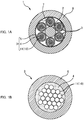
- Fig. 1A is a cross-sectional view of a loose-tube-type optical cable 1.
- This loose-tube-type optical cable 1 includes a tension member 2 (tensile member), a plurality of loose tubes 3, and a sheath 8.
- a plurality of loose tubes 3 are gathered around the tension member 2.
- the plurality of loose tubes 3 are gathered by being twisted (wound) around the periphery of the tension member 2 either helically in one direction, or in an S-Z configuration wherein the helical direction is inverted at certain intervals.
- the outer periphery of the plurality of loose tubes 3, which have been gathered around the tension member 2, is covered with a wrapping tape 7, a sheath material is extruded to the outer periphery of the wrapping tape 7 to form the sheath 8, to thereby manufacture the loose-tube-type optical cable 1 as shown in Fig. 1A .
- Fig. 1B is a cross-sectional view of a loose tube 3.
- An individual structure of the loose tube 3 may be herein referred to as an "optical cable” or a "loose-tube cable”.
- the loose tube 3 contains a plurality of optical fibers 11, a filler material 4, and a tube 5.
- the filler material 4 is a waterproof material to fill spaces inside the tube 5 and to stop water coming into the tube 5, for example, a gel.
- the tube 5 is a tubular member that houses the plurality of optical fibers 11 and the filler material 4.
- the plurality of optical fibers 11 are constituted by one or a plurality of optical fiber ribbons 10 with discontinuous connections.
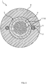
- Fig. 2 is a cross-sectional view of a loose-tube-type optical cable 1 of another embodiment.
- This loose-tube-type optical cable 1 includes two tension members 2 (tensile members), a loose tube 3, and a sheath 8.
- the optical cable 1 illustrated in Fig. 2 is also referred to as a center tube-type cable and the like.
- the loose tube 3 is arranged inside the sheath 8 so as to be disposed between the two tension members 2.
- the loose tube 3 contains a plurality of optical fibers 11, a filler material 4, and a tube 5.
- the plurality of optical fibers 11 are constituted by one or a plurality of optical fiber ribbons 10 each having discontinuous connections.
- the tension members 2 are arranged longitudinally along the loose tube 3, and the sheath 8 is formed by extruding a sheath material around the tension members 2 and the loose tube 3, to thereby manufacture the loose-tube-type optical cable 1 illustrated in Fig. 2 .
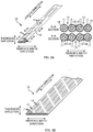
- FIG. 3A is an explanatory view of an example of an optical fiber ribbon 10 with discontinuous connections.
- a direction parallel to the optical fibers 11 is referred to as a "length direction”.
- a direction in which a plurality of optical fibers 11 constituting an optical fiber ribbon 10 with discontinuous connections are aligned is referred to as a "ribbon's width direction”.
- the optical fiber ribbon 10 with discontinuous connections is an optical fiber ribbon including a plurality of optical fibers 11 arranged side by side and connected at discontinuous parts. Two adjacent ones of the optical fibers 11 are connected with connection parts 12. A plurality of the connection parts 12 that connect two adjacent optical fibers 11 are arranged in a spaced-apart manner in the length direction. The plurality of connection parts 12 of the optical fiber ribbon 10 with discontinuous connections are arranged at certain intervals and two-dimensionally in the length direction and the ribbon's width direction.
- the connection parts 12 are formed by applying an ultraviolet cure resin to be an adhesive (connecting material 14) and then ultraviolet light is irradiated to cure the resin (described later) .
- the connection parts 12 can also be made of thermoplastic resin.
- Regions other than the connection parts 12 between the two adjacent optical fibers 11 constitute non-connected parts 13 (separated parts).
- the two adjacent optical fibers 11 are not restrained to each other.
- the optical fiber ribbon 10 with discontinuous connections can be rolled up into a tubular form (a bundle form), or folded up, and the multitude of optical fibers 11 can be housed with high density.
- a usual optical fiber ribbon 10 in which a plurality of optical fibers 11 arranged in the ribbon's width direction are covered all together may be used.
- FIG. 3B is an explanatory view of an example of an optical fiber ribbon 10 with discontinuous connections of another embodiment.
- the number of fibers of the optical fiber ribbon 10 with discontinuous connections may be changed appropriately.
- the arrangement of the connection parts 12 arranged at intervals may be changed appropriately.
- FIG. 4A is an explanatory view of wiping off the filler material 4 attached to the optical fiber ribbon 10.
- an operator takes out the optical fiber ribbon 10 with discontinuous connections from the loose tube 3 of the optical cable 1, and then wipes off the filler material 4 (for example, gel) attached to the optical fiber ribbon 10 with discontinuous connections with a cleaning sheet (for example, wiping paper).
- the filler material 4 for example, gel
- a cleaning sheet for example, wiping paper
- the plurality of optical fibers 11 constituting the optical fiber ribbon 10 are separated into individual fibers, the plurality of optical fibers 11 of the optical fiber ribbon 10 cannot be easily combined by fusion all together.
- This process takes a lot of time and effort.
- the connection parts 12 of the optical fiber ribbon 10 with discontinuous connections are preferably not destroyed when wiping off the filler material 4 attached to the optical fiber ribbon 10.
- FIG. 4B and FIG. 4C are cross-sectional views of the connection part 12 of two adjacent ones of the optical fibers 11 of the optical fiber ribbon 10 with discontinuous connections.
- FIG. 4B is an explanatory view of the connection part 12 that has been destroyed in the reference example.
- FIG. 4C is an explanatory view of the connection part 12 that has been destroyed in this embodiment.
- the optical fiber 11 is configured from an optical fiber part 11A, a cover layer 11B, and a colored layer 11C.
- the optical fiber 11 is also referred to as a primary coated optical fiber or a secondary coated optical fiber.
- a diameter of the optical fiber 11 is approximately 250 ⁇ m.
- the optical fiber part 11A is configured from a core and a clad.
- the optical fiber part 11A is, for example, a quartz glass fiber.
- a diameter (clad diameter) of the optical fiber part 11A is, for example, approximately 125 ⁇ m.
- the cover layer 11B is a layer that coats the optical fiber part 11A.
- the cover layer 11B is configured from, for example, a primary cover layer (primary coating) and a secondary cover layer (secondary coating) .
- the diameter of the cover layer 11B is, for example, approximately 240 ⁇ m.
- the colored layer 11C is a layer formed on a surface of the cover layer 11B.
- the colored layer 11C is formed by applying a coloring agent on a surface of the cover layer 11B.
- the coloring agent is usually colored, but may be colorless.
- the coloring agent is configured from an ultraviolet cure resin.
- the connection part 12 is formed by applying and curing the connecting material 14 (ultraviolet cure resin) on the surface of the colored layer 11C.
- connection part 12 As shown in FIG. 4B , the resin configuring the connection part 12 on the colored layer 11C has been destroyed in the reference example.
- the reason that the connection part 12 is destroyed in such a part is not clear. A possibility is that peeling occurred in an interface between the colored layer 11C and the connection part 12 (see the part in a thick line in the interface in the figure), a thin resin layer of the connection part 12 broke from this peeling, and the connection part 12 was destroyed.
- connection parts 12 when the connection parts 12 are split to separate the optical fibers 11 of the intermittently connected optical fiber ribbon 10 into single fibers, the connection parts 12 are destroyed with the colored layer 11C and the connection parts 12 still adhered together as shown in FIG. 4C , and in this way the optical fibers 11 are separated into single fibers.
- the optical fiber ribbon 10 with discontinuous connections is manufactured by selecting a connecting material 14 with an appropriate Young's modulus and breaking strength and adjusting adhesiveness between the colored layer 11C and the connection part 12.
- FIG. 5 is an explanatory view of a device 30 for manufacturing an optical fiber ribbon 10 with discontinuous connections of this embodiment.
- the device 30 for manufacturing has a plurality of fiber supply sources 31, a coloring device 40, and a ribbon forming device 50.
- the number of the fiber supply sources is four.
- the fiber supply sources 31 are supplying devices (supply sources) to supply optical fibers 11 to the coloring device 40.
- the optical fibers 11 to be supplied with the fiber supply sources 31 are optical fibers 11 that have not yet been formed with the colored layer 11C, i.e., optical fibers made of optical fiber part 11A and cover layer 11B.
- the coloring device 40 is a device to form the colored layer 11C to the outer periphery of the cover layer 11B.
- the coloring device 40 forms the colored layer 11C in the entire circumferential surface of the cover layer 11B in the length direction of the optical fibers 11.
- the coloring device 40 includes a coloring agent applying part 41 and a curing light source 42.
- the coloring agent applying part 41 is an applying device to apply a coloring agent made of ultraviolet cure resin to the outer periphery of the cover layer 11B.
- the coloring agent applying part 41 applies the coloring agent to the entire circumferential surface of the cover layer 11B along the length direction of the optical fibers 11 by, for example, inserting the optical fibers 11 through a coating die filled with a liquid coloring agent.
- the curing light source 42 is a light source to irradiate ultraviolet light to the coloring agent made of ultraviolet cure resin.
- the coloring agent applied to the outer periphery of the cover layer 11B is irradiated with ultraviolet light of the curing light source 42 and is cured.
- the colored layer 11C is formed with the cured coloring agent.
- the coloring device 40 supplies the optical fibers 11 formed with the colored layer 11C to the ribbon forming device 50.
- the ribbon forming device 50 is a device to form the connection parts 12 at certain intervals axially and to form the optical fiber ribbon 10 with discontinuous connections.
- FIG. 6A and FIG. 6B are explanatory views of the ribbon forming device 50.
- the ribbon forming device 50 has a connecting material applying part 51, a removing part 52, and a light source 53.
- the connecting material applying part 51 is a device to apply a connecting material 14 made of the ultraviolet cure resin between the adjacent optical fibers 11.
- the connecting material applying part 51 applies the liquid connecting material 14 to the entire circumferential surface of the optical fibers 11 (entire circumferential surface of colored layer 11C) and between the optical fibers 11, along the length direction of the optical fibers 11, by inserting the plurality of optical fibers 11 through the coating die filled with the liquid connecting material 14.
- the number of the optical fibers is four.
- the removing part 52 is a device to remove a part of the liquid connecting material 14 applied between the optical fibers 11, while leaving a part of the liquid connecting material 14 on the optical fibers 11.
- the removing part 52 includes rotary blades 521 each having a recessed part 521A. See FIG. 6A .
- the removing part 52 makes the rotary blade 521 rotate in synchronism with a supplying speed of the optical fibers 11, and removes or cuts the connecting material 14 applied between the optical fibers 11 with an outer edge of the rotary blade 521 while leaving the connecting material 14 in the recessed part 521A of the rotary blade 521.
- the removing part 52 removes a part of the liquid connecting material 14 applied between the optical fibers 11 by scraping the connecting material 14 with the outer edge of the rotary blade 521.
- the light source 53 is a light source to irradiate ultraviolet light to the connecting material 14 made of ultraviolet cure resin.
- the light source 53 has a preliminary curing light source 53A and a main curing light source 53B.
- the preliminary curing light source 53A irradiates ultraviolet light to preliminarily cure the connecting material 14.
- the temporarily cured connecting material 14 is not completely cured, but curing of the surface has advanced.
- the main curing light source 53B irradiates ultraviolet light more intense than the preliminary curing light source 53A to fully cure the connecting material 14.
- the fully cured ultraviolet cure resin is in a state cured to the inside (the optical fiber ribbon 10 with discontinuous connections, however, can be rolled into a tubular shape or folded, thus the fully cured connection parts 12 have appropriate elasticity).
- the optical fibers 11 that have just come out the connecting material applying part 51 and the removing part 52 are arranged with a space between each other.
- the preliminary curing light source 53A irradiates ultraviolet light to the connecting material 14 in this state, and temporarily cures the connecting material 14.
- the ribbon forming device 50 gradually narrows the space between the optical fibers 11, aligns the plurality of the optical fibers 11 side by side, and gathers the optical fibers into a ribbon shape. Because the connecting material 14 has preliminarily cured, even when the parts from which the connecting material 14 has been removed (separated parts) contact each other, such parts do not have to be connected.
- the colored layer 11C and the connection parts 12 are formed as follows.
- radical polymerizable ultraviolet cure resin is used as a coloring agent to form the colored layer 11C
- oxygen concentration when forming the colored layer 11C is adjusted by adjusting oxygen concentration of the coloring device 40
- a degree of cure of the surface of the colored layer 11C is adjusted such that uncured resin is left on the surface of the colored layer 11C.
- oxygen concentration of the coloring device 40 is increased, oxygen inhibition occurs on the surface of the coloring agent that is the radical polymerizable ultraviolet cure resin, thus uncured resin on the surface of the colored layer 11C increases, and the degree of cure of the surface of the colored layer 11C is lowered.
- uncured resin remains on the surface of the colored layer 11C, the inside of the colored layer 11C is cured, thus manufacturing of the optical fibers 11 becomes easier compared to the state where the inside of the colored layer 11C is uncured.
- FIG. 7 is an explanatory view of the degree of cure of a surface of the colored layer 11C.
- a graph in the figure shows measurement results of an infrared absorption spectrum.
- a horizontal axis in the graph shows a wave number (cm -1 ), and a vertical axis shows absorbance.
- a peak intensity of a band of a double bond of a photopolymerization reaction of a coloring agent (ultraviolet cure resin) is measured, and this measurement value is A.
- a band of CH out-of-plane bending vibration of a vinyl group is around 808 cm -1 .
- the degree of cure of the surface of the colored layer 11C in an uncured state is 0%
- the degree of cure of the surface of the colored layer 11C when the coloring agent is cured in an oxygen-free condition (most cured state) is 100%.
- the oxygen concentration is measureable using an oximeter attached inside the coloring device 40.
- the colored layer 11C (before connection parts 12 are formed) is formed such that the degree of cure of the surface of the colored layer 11C is 60% to 90%.
- the degree of cure of the surface of the colored layer 11C is greater than 90%, peeling easily occurs in the interface between the colored layer 11C and the connection part 12 (refer to bold line part in interface in FIG. 4B ), thus when wiping off the filler material 4 attached to the optical fiber ribbon 10 (refer to FIG. 4A ), there is a possibility that the connection parts 12 are destroyed unintentionally.
- the degree of cure of the surface of the colored layer 11C is less than 60%, adhesiveness between the colored layer 11C and the connection parts 12 is too high, and there is a possibility that the cover layer 11B is destroyed with the connection parts 12 when separating the optical fibers 11 of the optical fiber ribbon 10 with discontinuous connections into single fibers.
- the degree of cure of the surface of the colored layer 11C is 60% to 90%, the connection parts 12 can be suppressed from being destroyed unintentionally, and also the cover layer 11B can be suppressed from being destroyed when separating the optical fibers 11 into single fibers, as described below.
- the oxygen concentration when forming the colored layer 11C is adjusted to 0.10% to 1.0%.
- the degree of cure of the surface of the colored layer 11C becomes greater than 90% because the oxygen concentration is low, and as a result, when wiping off the filler material 4 attached to the optical fiber ribbon 10 (refer to FIG. 4A ), there is a possibility that the connection parts 12 are unintentionally destroyed.
- the oxygen concentration when forming the colored layer 11C is greater than 1.0%, adhesiveness between the colored layer 11C and the connection part 12 is too high, and there is a possibility that the cover layer 11B is destroyed also with the connection parts 12 when separating the optical fibers 11 of the optical fiber ribbon 10 with discontinuous connections into single fibers.
- the ribbon forming device 50 After forming the colored layer 11C by adjusting the degree of cure of the surface as described above, the ribbon forming device 50 forms the connection parts 12.
- radical polymerizable ultraviolet cure resin is used also for the connecting material 14 forming the connection parts 12.
- the ribbon forming device 50 applies liquid connecting material 14 to the entire circumferential surface of the colored layer 11C and between the optical fibers 11 with the connecting material applying part 51, removes a part of the liquid connecting material 14 applied between the optical fibers 11 with the removing part 52, and irradiates ultraviolet light to the connecting material 14 with the light source 53.
- the connecting material 14 which is the radical polymerizable ultraviolet cure resin is applied on the surface of the colored layer 11C with the uncured resin remaining, and ultraviolet light is irradiated on the connecting material 14.
- the photopolymerization initiator of the connecting material 14 becomes radical, and the connecting material 14 cures and forms the connection parts 12, and uncured resin on the surface of the colored layer 11C also cures.
- adhesiveness between the colored layer 11C and the connection parts 12 becomes high, and peeling in the interface between the colored layer 11C and the connection part 12 can be suppressed.
- the liquid connecting material 14 when applying the connecting material 14, the liquid connecting material 14 is applied to the entire circumferential surface of the colored layer 11C, thus a layer of the connecting material 14 is formed in the entire circumferential surface of the optical fiber 11 (refer to FIG. 4C ). For this reason, the colored layer 11C is not exposed in the optical fiber ribbon 10 with discontinuous connections that has been completed, so that uncured resin does not have to be exposed. The uncured resin remains on the surface of the colored layer 11C when forming the colored layer 11C, but in the case where the liquid connecting material 14 is applied on the entire circumferential surface of the colored layer 11C, the uncured resin on the surface of the colored layer 11C is cured when forming the connection parts 12. Accordingly, even if the completed optical fiber ribbon 10 with discontinuous connections is analyzed, it is impossible or unrealistic to specify the characteristic of making uncured resin remain on the surface of the colored layer 11C when forming the colored layer 11C.
- a 12-fiber optical fiber ribbon 10 with discontinuous connections was manufactured with the above-described manufacturing method.
- a urethane acrylate based ultraviolet cure resin (resin A: Young's modulus of 800 MPa, breaking strength of 50 MPa) was used as the connecting material 14.
- oxygen concentration when forming the colored layer 11C from a range of an oxygen-free condition (oxygen concentration is less than 0.001% of measurement limit) to 1.0%, the degree of cure of the surface of the colored layer 11C is gradually adjusted in a range of 100% to 60%.
- the degree of cure of the surface of the colored layer 11C is measured.
- a test to wipe off the gel adhered to the optical fiber ribbon 10 with discontinuous connections that has been manufactured is performed, to evaluate whether or not there is destruction in the connection parts 12 after wiping off the gel.
- a test to split the connection parts 12 of the optical fiber ribbon 10 with discontinuous connections and separate the optical fibers 11 into single fibers is performed, to evaluate also whether or not there is destruction in the cover layer 11B of the optical fiber 11 after being separated into a single fiber (after the connection parts 12 have been split).
- Example 1 The experiment results of Example 1 are shown in Table 1 below.
- Table 1 Sample number Connecting material Young's modulus [MPa] Breaking strength [MPa] Oxygen concentration when forming colored layer Degree of cure of surface of colored layer Destruction in connection part after wiping Destruction in cover layer of optical fiber separated into single fiber
- Resin A 800 50 1.0% 60% No Yes A2 0.30% 85% No Yes A3 0.10% 90% No Yes A4 0.03% 94% Yes Yes A5 0.01% 96% Yes Yes A6 0.003% 99% Yes Yes A7 less than 0.001% 100% Yes Yes Yes Yes
- connection part 12 was destroyed when wiping off the gel. The reason of the above is considered that peeling was likely to occur in the interface between the colored layer 11C and the connection part 12.
- Example 1 the cover layer 11B of the optical fiber 11 that has been separated into single fibers had been destroyed in all of the samples (sample numbers A1 to A7).
- the reason of this result is considered that the Young's modulus and the breaking strength of the connection part 12 formed with resin A was high. It is to be noted that in the case where connection part 12 is formed with resin A, the effect of suppressing destruction in the connection part 12 that has been wiped can be achieved, as described above.
- a 12-fiber optical fiber ribbon 10 with discontinuous connections was manufactured similar to Example 1 using a different resin (connecting material 14) for forming the connection parts 12 from that in Example 1.
- the Young's modulus and breaking strength of resin B to resin F are shown in Table 2. Further, as similar to Example 1, evaluation of whether or not there is destruction in the connection part 12 from which the gel has been wiped off, and evaluation of whether or not there is destruction in the cover layer 11B of the optical fiber 11 that has been separated into single fibers are performed.
- Example 2 In the case where there is no destruction in the connection part 12 from which the gel has been wiped off, and there was no destruction in the cover layer 11B of the optical fiber 11 that has been separated into a single fiber, the result was determined "satisfactory", and in the case where there was destruction in at least one of the above, the result was determined "non-satisfactory".
- the experiment results of Example 2 are shown in Table 2 below.
- connection part 12 is formed with resin B to resin E
- the colored layer 11C is formed with the degree of cure of the surface of the colored layer 11C 60% to 90% (oxygen concentration of when forming colored layer 11C is 0.10% to 1.0%), destruction of the connection part 12 when wiping the gel can be suppressed.
- connection part 12 is formed with resin B to resin E with the Young's modulus of 10 to 300 MPa and the breaking strength of 10 to 30 MPa, then not only can destruction in the connection part 12 when wiping off the gel be suppressed, but also destruction in the cover layer 11B of the optical fiber 11 that has been separated into a single fiber can also be suppressed.
- the connection part 12 is formed with the above-described resin A, the cover layer 11B of the optical fiber 11 that has been separated into a single fiber was destroyed.
- resin that forms the connection part 12 has the Young's modulus of 10 to 300 MPa and the breaking strength of 10 to 30 MPa.
- a 12-fiber optical fiber ribbon 10 with discontinuous connections is manufactured similarly to Examples 1, 2 with a varying thickness of the connection part 12 (size in thickness direction in FIG. 4C ).
- the colored layer 11C is formed with the degree of cure of the surface of the colored layer 11C 60% to 90%, and the connection part 12 is formed with resin B to resin E having the Young's modulus of 10 to 300 MPa and the breaking strength of 10 to 30 MPa.
- evaluation of whether or not there is destruction in the connection part 12 from which the gel has been wiped off, and evaluation of whether or not there is destruction in the cover layer 11B of the optical fiber 11 that has been separated into a single fiber is performed. Experiment results of Example 3 are shown in Table 3 below.
- the connection part 12 In the case where the thickness of the connection part 12 is equal to or smaller than 120 ⁇ m, the connection part 12 after wiping off of the gel was destroyed. On the other hand, in the case where the thickness of the connection part 12 is equal to or greater than 150 ⁇ m, destruction of the connection part 12 after wiping off of the gel can be suppressed. Even when the thickness of the connection part 12 is equal to or greater than 150 ⁇ m, the cover layer 11B of the optical fiber 11 that has been separated into a single fiber has not been destroyed. From the above, it is preferable that the thickness of the connection part 12 is equal to or greater than 150 ⁇ m.
- FIG. 8A is a cross-sectional view of a connection part 12 of adjacent 2-fiber optical fibers 11 of an optical fiber ribbon 10 with discontinuous connections in a second embodiment.
- the connection part 12 may be configured such that the thickness (size in thickness direction) of the connection part 12 is uniform.
- the liquid connecting material 14 when applying the connecting material 14, the liquid connecting material 14 is applied to the entire circumferential surface of the colored layer 11C, and in this way, a layer of the connecting material 14 is formed to the entire circumferential surface of the optical fiber 11.
- the colored layer 11C is not exposed, and thus uncured resin does not have to be exposed.
- FIG. 8B is a cross-sectional view of a connection part 12 of adjacent 2-fiber optical fibers 11 of an optical fiber ribbon 10 with discontinuous connections in Embodiment 3. As shown in Embodiment 3, the connection part 12 may be formed only in between the optical fibers 11.
- FIG. 8C is a cross-sectional view of a connection part 12 of adjacent 2-fiber optical fibers 11 of an optical fiber ribbon 10 with discontinuous connections in a fourth embodiment.
- the connection part 12 is not formed equally in the thickness direction, and the connection part 12 may be formed as displaced to one side in the thickness direction (upper side in the figure).
- the connecting material 14 is applied only partially to the periphery of the optical fiber 11.
- the colored layer 11C will be exposed even after the optical fiber ribbon 10 with discontinuous connections has been completed. Because the connecting material 14 is not applied to the exposed section of the colored layer 11C, uncured resin will remain on the surface of the colored layer 11C of this section even after the optical fiber ribbon 10 with discontinuous connections has been completed.
- connection part 12 in the third embodiment and the fourth embodiment the connecting material 14 does not have to be applied to the entire circumferential surface of the optical fiber 11, thus for example, a method to eject the connecting material 14 toward the optical fiber 11 can be adopted, and there is an advantage that a degree of freedom in the application method of the connecting material 14 increases.
- radical polymerizable ultraviolet cure resin is used as a coloring agent to form the colored layer 11C
- the oxygen concentration when forming the colored layer 11C is adjusted by adjusting oxygen concentration of the coloring device 40
- the degree of cure of the surface of the colored layer 11C is adjusted such that uncured resin remains on the surface of the colored layer 11C.
- the colored layer 11C (before the connection part 12 is formed) is preferably formed such that the degree of cure of the surface of the colored layer 11C is 60% to 90%.
- the optical fiber ribbon 10 with discontinuous connections is manufactured by applying the connecting material 14 that is the radical polymerizable ultraviolet cure resin to the surface of the colored layer 11C on which uncured resin remains, and irradiating ultraviolet light to the connecting material 14 to form the connection part 12.
- the connecting material 14 that is the radical polymerizable ultraviolet cure resin
- the connecting material 14 irradiating ultraviolet light to the connecting material 14 to form the connection part 12.
- the degree of cure of the surface of the colored layer 11C is adjusted such that uncured resin remains on the surface of the colored layer 11C by adjusting the oxygen concentration when forming the colored layer 11C.
- the degree of cure of the surface of the colored layer 11C may be adjusted such that uncured resin remains on the surface of the colored layer 11C.
- the colored layer 11C is preferably formed such that the degree of cure of the surface of the colored layer 11C is 60% to 90%.
Landscapes
- Physics & Mathematics (AREA)
- Engineering & Computer Science (AREA)
- Life Sciences & Earth Sciences (AREA)
- Chemical & Material Sciences (AREA)
- Optics & Photonics (AREA)
- General Physics & Mathematics (AREA)
- Manufacturing & Machinery (AREA)
- General Life Sciences & Earth Sciences (AREA)
- Chemical Kinetics & Catalysis (AREA)
- General Chemical & Material Sciences (AREA)
- Geochemistry & Mineralogy (AREA)
- Materials Engineering (AREA)
- Organic Chemistry (AREA)
- Optical Fibers, Optical Fiber Cores, And Optical Fiber Bundles (AREA)
- Surface Treatment Of Glass Fibres Or Filaments (AREA)
Abstract


Description
- The present invention relates to a method for manufacturing an optical fiber ribbon, an optical fiber ribbon, and an optical cable.
-
Patent Literatures Patent Literature 3 discloses an optical cable (loose-tube-type optical cable) in which a tube is filled with gel as a filler material (waterproof material). -
- Patent Literature 1: Japanese Patent No.
4143651 - Patent Literature 2: Japanese Patent No.
4619424 - Patent Literature 3: Japanese Patent No.
5260940 - When taking out an optical fiber ribbon from a loose-tube-type optical cable, filler material (gel and the like) attached to the periphery of optical fibers needs to be wiped off. In the case of an optical fiber ribbon with discontinuous connections, however, when wiping off the filler material attached to the optical fiber ribbon, there is a possibility that connection parts that connect the optical fibers are destroyed, and that the optical fiber ribbon comes apart into single optical fibers.
- An objective of this invention is to suppress destruction in the connection parts.
- A primary aspect of the invention for achieving the aforementioned objective is a method for manufacturing an optical fiber ribbon including:
- colored layer forming to form a colored layer to each of a plurality of optical fibers; and
- ribbon forming to form an optical fiber ribbon by curing a connecting material applied to a surface of the colored layer of each of the optical fibers to form connection parts that connect adjacent ones of the optical fibers,
- the colored layer forming comprising,
- applying a coloring agent to the optical fibers, and
- forming the colored layer by curing the coloring agent such that uncured resin remains on the surface, and
- the ribbon forming comprising,
- applying the connecting material to the surface of the colored layer on which the uncured resin remains, and
- curing the connecting material and the uncured resin on the surface of the colored layer.
- Other features of the invention are made clear by the following description and the drawings.
- According to this invention, connection parts can be suppressed from being destroyed.
-
- [
Fig. 1] Fig. 1A is a cross-sectional view of a loose-tube-typeoptical cable 1.FIG. 1B is a cross-sectional view of aloose tube 3. - [
Fig. 2] FIG. 2 is a cross-sectional view of another loose-tube-typeoptical cable 1. - [
Fig. 3] FIG. 3A is an explanatory view of an example of anoptical fiber ribbon 10 with discontinuous connections.FIG. 3B is an explanatory view of another example of anoptical fiber ribbon 10 with discontinuous connections. - [
Fig. 4] FIG. 4A is an explanatory view of wiping offfiller material 4 attached to anoptical fiber ribbon 10.FIG. 4B and FIG. 4C are cross-sectional views of aconnection part 12 between two adjacentoptical fibers 11 of anoptical fiber ribbon 10 with discontinuous connections.FIG. 4B is an explanatory view of aconnection part 12 that has been destroyed in a reference example.FIG. 4C is an explanatory view of aconnection part 12 that has been destroyed in this embodiment. - [
Fig. 5] FIG. 5 is an explanatory view of adevice 30 for manufacturing anoptical fiber ribbon 10 with discontinuous connections of this embodiment. - [
Fig. 6] FIG. 6A and FIG. 6B are explanatory views of aribbon forming device 50. - [
Fig. 7] FIG. 7 is an explanatory view of degree of cure of a surface of acolored layer 11C. - [
Fig. 8] FIG. 8A is a cross-sectional view of aconnection part 12 of two adjacent ones of theoptical fibers 11 of anoptical fiber ribbon 10 with discontinuous connections of a second embodiment.FIG. 8B is a cross-sectional view of aconnection part 12 of two adjacent ones of theoptical fibers 11 of anoptical fiber ribbon 10 with discontinuous connections of a third embodiment.FIG. 8C is a cross-sectional view of aconnection part 12 of two adjacent ones of theoptical fibers 11 of anoptical fiber ribbon 10 with discontinuous connections of a fourth embodiment. - At least the following matters are disclosed in the following description and the drawings.
- A method for manufacturing an optical fiber ribbon will become clear, including:
- colored layer forming to form a colored layer to each of a plurality of optical fibers; and
- ribbon forming to form an optical fiber ribbon by curing a connecting material applied to a surface of the colored layer of each of the optical fibers to form connection parts that connect adjacent ones of the optical fibers,
- the colored layer forming comprising,
- applying a coloring agent to the optical fibers, and
- forming the colored layer by curing the coloring agent such that uncured resin remains on the surface, and
- the ribbon forming comprising,
- applying the connecting material to the surface of the colored layer on which the uncured resin remains, and
- curing the connecting material and the uncured resin on the surface of the colored layer. According to this method for manufacturing such an optical fiber ribbon, destruction in the connection parts can be suppressed.
- The colored layer forming preferably including, applying the coloring agent made of radical polymerizable ultraviolet cure resin to the optical fibers, and forming the colored layer by irradiating ultraviolet light to the coloring agent while making the uncured resin remain on the surface due to oxygen inhibition, and the ribbon forming preferably including, applying the connecting material made of radical polymerizable ultraviolet cure resin to the surface of the colored layer on which the uncured resin remains, and by irradiating ultraviolet light to the connecting material, curing the connecting material and the uncured resin on the surface of the colored layer. In this way, the uncured resin can be made to remain on the surface and the inside can be cured when forming the colored layer, and thus manufacturing the optical fibers becomes easy.
- The ribbon forming preferably including, applying the connecting material to an entire circumferential surface of the optical fibers each formed with the colored layer, and by irradiating ultraviolet light to the connecting material, curing the connecting material applied to the entire circumference of the optical fibers and the uncured resin on the surface of the colored layer. In this way, it is possible to suppress the uncured resin from remaining in the optical fiber ribbon that has been manufactured.
- The ribbon forming preferably including, applying the connecting material between the optical fibers and on the entire circumferential surface of the optical fibers each formed with the colored layer, removing a part of the connecting material applied between the optical fibers while making the connecting material applied between the optical fibers remain, and forming the connection parts at discontinuous parts by irradiating ultraviolet light to the connecting material and curing the connecting material. In this way, applying the connecting material to the entire circumference of the optical fiber and intermittently forming the connection parts can be easily achieved.
- The colored layer forming preferably including, in an atmosphere with oxygen concentration of 0.10% to 1.0%, while making the uncured resin remain on the surface due to oxygen inhibition, irradiating the coloring agent with ultraviolet light to form the colored layer. In this way, destruction in the connection parts can be suppressed.
- When peak intensity of a band of a double bond of a photopolymerization reaction when measuring a surface of the colored layer with infrared absorption spectrum is A, the peak intensity when the coloring agent is uncured is A0, the peak intensity when the coloring agent is cured the most is A1, and a degree of cure of a surface of the colored layer is represented by degree of cure (%) = {(A0 - A) / (A0 - A1)} × 100, the colored layer is preferably formed such that the degree of cure is 60% to 90%. In this way, destruction in the connection parts can be suppressed.
- A Young's modulus of the connecting material is preferably 10 to 300 MPa and a breaking strength of the connecting material is preferably 10 to 30 MPa. In this way, the optical fibers can be suppressed from being damaged when individually separating the optical fibers of the optical fiber ribbon.
- A thickness of the connection part is preferably equal to or greater than 150 µm. In this way, destruction in the connection parts can be suppressed.
- An optical fiber ribbon will become clear, including: a plurality of optical fibers each having a colored layer, the plurality of optical fibers being arranged side by side; and connection parts each connecting two fibers of the optical fibers adjacent to each other, wherein the colored layer is formed by curing a coloring agent such that uncured resin remains on a surface, a connecting material is applied to a surface of the colored layer with the uncured resin remaining, and the connection parts are formed by curing the connecting material, and the uncured resin on the surface of the colored layer is cured. According to such an optical fiber ribbon, destruction in the connection parts can be suppressed.
- An optical cable will become clear, including:
- a plurality of optical fibers each having a colored layer and arranged side by side, an optical fiber ribbon having connection parts that connect two fibers of the optical fibers adjacent to each other;
- a tube that houses the optical fiber ribbon; and
- a filler material filling the tube, wherein
- the colored layer is formed by curing a coloring agent such that uncured resin remains on a surface,
- a connecting material is applied on a surface of the colored layer on which the uncured resin remains, and
- the connecting material is cured to form the connection parts, and the uncured resin on the surface of the colored layer is cured. With such an optical cable, destruction in the connection parts can be suppressed when wiping off the filler material adhered to the optical fiber ribbon.
-
Fig. 1A is a cross-sectional view of a loose-tube-typeoptical cable 1. This loose-tube-typeoptical cable 1 includes a tension member 2 (tensile member), a plurality ofloose tubes 3, and asheath 8. A plurality ofloose tubes 3 are gathered around thetension member 2. The plurality ofloose tubes 3 are gathered by being twisted (wound) around the periphery of thetension member 2 either helically in one direction, or in an S-Z configuration wherein the helical direction is inverted at certain intervals. The outer periphery of the plurality ofloose tubes 3, which have been gathered around thetension member 2, is covered with a wrappingtape 7, a sheath material is extruded to the outer periphery of the wrappingtape 7 to form thesheath 8, to thereby manufacture the loose-tube-typeoptical cable 1 as shown inFig. 1A . -
Fig. 1B is a cross-sectional view of aloose tube 3. An individual structure of theloose tube 3 may be herein referred to as an "optical cable" or a "loose-tube cable". Theloose tube 3 contains a plurality ofoptical fibers 11, afiller material 4, and atube 5. Thefiller material 4 is a waterproof material to fill spaces inside thetube 5 and to stop water coming into thetube 5, for example, a gel. Thetube 5 is a tubular member that houses the plurality ofoptical fibers 11 and thefiller material 4. The plurality ofoptical fibers 11 are constituted by one or a plurality ofoptical fiber ribbons 10 with discontinuous connections. -
Fig. 2 is a cross-sectional view of a loose-tube-typeoptical cable 1 of another embodiment. This loose-tube-typeoptical cable 1 includes two tension members 2 (tensile members), aloose tube 3, and asheath 8. Theoptical cable 1 illustrated inFig. 2 is also referred to as a center tube-type cable and the like. Theloose tube 3 is arranged inside thesheath 8 so as to be disposed between the twotension members 2. Also in theoptical cable 1 ofFig. 2 , theloose tube 3 contains a plurality ofoptical fibers 11, afiller material 4, and atube 5. The plurality ofoptical fibers 11 are constituted by one or a plurality ofoptical fiber ribbons 10 each having discontinuous connections. Thetension members 2 are arranged longitudinally along theloose tube 3, and thesheath 8 is formed by extruding a sheath material around thetension members 2 and theloose tube 3, to thereby manufacture the loose-tube-typeoptical cable 1 illustrated inFig. 2 . -
FIG. 3A is an explanatory view of an example of anoptical fiber ribbon 10 with discontinuous connections. In the below explanation, a direction parallel to theoptical fibers 11 is referred to as a "length direction". A direction in which a plurality ofoptical fibers 11 constituting anoptical fiber ribbon 10 with discontinuous connections are aligned is referred to as a "ribbon's width direction". - The
optical fiber ribbon 10 with discontinuous connections is an optical fiber ribbon including a plurality ofoptical fibers 11 arranged side by side and connected at discontinuous parts. Two adjacent ones of theoptical fibers 11 are connected withconnection parts 12. A plurality of theconnection parts 12 that connect two adjacentoptical fibers 11 are arranged in a spaced-apart manner in the length direction. The plurality ofconnection parts 12 of theoptical fiber ribbon 10 with discontinuous connections are arranged at certain intervals and two-dimensionally in the length direction and the ribbon's width direction. Theconnection parts 12 are formed by applying an ultraviolet cure resin to be an adhesive (connecting material 14) and then ultraviolet light is irradiated to cure the resin (described later) . Theconnection parts 12 can also be made of thermoplastic resin. Regions other than theconnection parts 12 between the two adjacentoptical fibers 11 constitute non-connected parts 13 (separated parts). In thenon-connected parts 13, the two adjacentoptical fibers 11 are not restrained to each other. Thus, theoptical fiber ribbon 10 with discontinuous connections can be rolled up into a tubular form (a bundle form), or folded up, and the multitude ofoptical fibers 11 can be housed with high density. Instead of theoptical fiber ribbon 10 with discontinuous connections, however, a usualoptical fiber ribbon 10 in which a plurality ofoptical fibers 11 arranged in the ribbon's width direction are covered all together may be used. -
FIG. 3B is an explanatory view of an example of anoptical fiber ribbon 10 with discontinuous connections of another embodiment. In this way, the number of fibers of theoptical fiber ribbon 10 with discontinuous connections may be changed appropriately. The arrangement of theconnection parts 12 arranged at intervals may be changed appropriately. -
FIG. 4A is an explanatory view of wiping off thefiller material 4 attached to theoptical fiber ribbon 10. As shown inFIG. 4A , an operator takes out theoptical fiber ribbon 10 with discontinuous connections from theloose tube 3 of theoptical cable 1, and then wipes off the filler material 4 (for example, gel) attached to theoptical fiber ribbon 10 with discontinuous connections with a cleaning sheet (for example, wiping paper). At this time, when fingers of the operator exert a force of twisting theoptical fiber ribbon 10, theconnection parts 12 of theoptical fiber ribbon 10 with discontinuous connections may be destroyed. As a result, theoptical fiber ribbon 10 with discontinuous connections is separated into individual optical fibers 11 (a plurality of theoptical fibers 11 constituting theoptical fiber ribbon 10 are separated into individually separated fibers). When the plurality ofoptical fibers 11 constituting theoptical fiber ribbon 10 are separated into individual fibers, the plurality ofoptical fibers 11 of theoptical fiber ribbon 10 cannot be easily combined by fusion all together. Thus, in order to fusion splice theoptical fibers 11, it is necessary to fusion splice each of the individualoptical fibers 11, or connect the plurality ofoptical fibers 11 that have been individually separated again into a ribbon shape and then fuse the fibers all together. This process takes a lot of time and effort. In order to avoid such time and effort, theconnection parts 12 of theoptical fiber ribbon 10 with discontinuous connections are preferably not destroyed when wiping off thefiller material 4 attached to theoptical fiber ribbon 10. -
FIG. 4B and FIG. 4C are cross-sectional views of theconnection part 12 of two adjacent ones of theoptical fibers 11 of theoptical fiber ribbon 10 with discontinuous connections.FIG. 4B is an explanatory view of theconnection part 12 that has been destroyed in the reference example.FIG. 4C is an explanatory view of theconnection part 12 that has been destroyed in this embodiment. - As shown in
FIG. 4B and FIG. 4C , theoptical fiber 11 is configured from anoptical fiber part 11A, acover layer 11B, and acolored layer 11C. Theoptical fiber 11 is also referred to as a primary coated optical fiber or a secondary coated optical fiber. A diameter of theoptical fiber 11 is approximately 250 µm. Theoptical fiber part 11A is configured from a core and a clad. Theoptical fiber part 11A is, for example, a quartz glass fiber. A diameter (clad diameter) of theoptical fiber part 11A is, for example, approximately 125 µm. Thecover layer 11B is a layer that coats theoptical fiber part 11A. Thecover layer 11B is configured from, for example, a primary cover layer (primary coating) and a secondary cover layer (secondary coating) . The diameter of thecover layer 11B is, for example, approximately 240 µm. Thecolored layer 11C is a layer formed on a surface of thecover layer 11B. Thecolored layer 11C is formed by applying a coloring agent on a surface of thecover layer 11B. The coloring agent is usually colored, but may be colorless. As will be described later, the coloring agent is configured from an ultraviolet cure resin. As will be described later, theconnection part 12 is formed by applying and curing the connecting material 14 (ultraviolet cure resin) on the surface of thecolored layer 11C. - As shown in
FIG. 4B , the resin configuring theconnection part 12 on thecolored layer 11C has been destroyed in the reference example. The reason that theconnection part 12 is destroyed in such a part is not clear. A possibility is that peeling occurred in an interface between thecolored layer 11C and the connection part 12 (see the part in a thick line in the interface in the figure), a thin resin layer of theconnection part 12 broke from this peeling, and theconnection part 12 was destroyed. - In this embodiment, by improving adhesiveness between the
colored layer 11C and theconnection part 12 as described below, it is achieved that peeling in the interface between thecolored layer 11C and theconnection part 12 does not easily occur. As a result, destruction in the thin resin layer of theconnection part 12 is suppressed in this embodiment, and destruction in theconnection part 12 advances with thecolored layer 11C and theconnection parts 12 still adhered together as shown inFIG. 4C , so that theconnection part 12 is not easily destroyed compared to the reference example inFIG. 4B , and theoptical fibers 11 can be suppressed from unintentionally being separated into single fibers. In this embodiment, when theconnection parts 12 are split to separate theoptical fibers 11 of the intermittently connectedoptical fiber ribbon 10 into single fibers, theconnection parts 12 are destroyed with thecolored layer 11C and theconnection parts 12 still adhered together as shown inFIG. 4C , and in this way theoptical fibers 11 are separated into single fibers. - On the other hand, in the case where adhesiveness between the
colored layer 11C and theconnection parts 12 is too high, when theconnection parts 12 are split because theoptical fibers 11 of theoptical fiber ribbon 10 with discontinuous connections need to be separated into single fibers, thecover layer 11B as well as theconnection parts 12 is destroyed, and there is a possibility that theoptical fibers 11 are damaged. Further, when the Young's modulus and a breaking strength of theconnection parts 12 is too high, thecover layer 11B as well as theconnection parts 12 are destroyed, and there is a possibility that theoptical fibers 11 are damaged. Thus, in this embodiment, it is preferable that theoptical fiber ribbon 10 with discontinuous connections is manufactured by selecting a connectingmaterial 14 with an appropriate Young's modulus and breaking strength and adjusting adhesiveness between thecolored layer 11C and theconnection part 12. -
FIG. 5 is an explanatory view of adevice 30 for manufacturing anoptical fiber ribbon 10 with discontinuous connections of this embodiment. Thedevice 30 for manufacturing has a plurality offiber supply sources 31, acoloring device 40, and aribbon forming device 50. Here, the number of the fiber supply sources is four. - The
fiber supply sources 31 are supplying devices (supply sources) to supplyoptical fibers 11 to thecoloring device 40. Theoptical fibers 11 to be supplied with thefiber supply sources 31 areoptical fibers 11 that have not yet been formed with thecolored layer 11C, i.e., optical fibers made ofoptical fiber part 11A andcover layer 11B. - The
coloring device 40 is a device to form thecolored layer 11C to the outer periphery of thecover layer 11B. Thecoloring device 40 forms thecolored layer 11C in the entire circumferential surface of thecover layer 11B in the length direction of theoptical fibers 11. Thecoloring device 40 includes a coloringagent applying part 41 and a curinglight source 42. The coloringagent applying part 41 is an applying device to apply a coloring agent made of ultraviolet cure resin to the outer periphery of thecover layer 11B. The coloringagent applying part 41 applies the coloring agent to the entire circumferential surface of thecover layer 11B along the length direction of theoptical fibers 11 by, for example, inserting theoptical fibers 11 through a coating die filled with a liquid coloring agent. The curinglight source 42 is a light source to irradiate ultraviolet light to the coloring agent made of ultraviolet cure resin. The coloring agent applied to the outer periphery of thecover layer 11B is irradiated with ultraviolet light of the curinglight source 42 and is cured. Thecolored layer 11C is formed with the cured coloring agent. Thecoloring device 40 supplies theoptical fibers 11 formed with thecolored layer 11C to theribbon forming device 50. - The
ribbon forming device 50 is a device to form theconnection parts 12 at certain intervals axially and to form theoptical fiber ribbon 10 with discontinuous connections.FIG. 6A and FIG. 6B are explanatory views of theribbon forming device 50. Theribbon forming device 50 has a connectingmaterial applying part 51, a removingpart 52, and alight source 53. - The connecting
material applying part 51 is a device to apply a connectingmaterial 14 made of the ultraviolet cure resin between the adjacentoptical fibers 11. The connectingmaterial applying part 51 applies theliquid connecting material 14 to the entire circumferential surface of the optical fibers 11 (entire circumferential surface ofcolored layer 11C) and between theoptical fibers 11, along the length direction of theoptical fibers 11, by inserting the plurality ofoptical fibers 11 through the coating die filled with theliquid connecting material 14. Here, the number of the optical fibers is four. - The removing
part 52 is a device to remove a part of theliquid connecting material 14 applied between theoptical fibers 11, while leaving a part of theliquid connecting material 14 on theoptical fibers 11. The removingpart 52 includesrotary blades 521 each having a recessedpart 521A. SeeFIG. 6A . The removingpart 52 makes therotary blade 521 rotate in synchronism with a supplying speed of theoptical fibers 11, and removes or cuts the connectingmaterial 14 applied between theoptical fibers 11 with an outer edge of therotary blade 521 while leaving the connectingmaterial 14 in the recessedpart 521A of therotary blade 521. In other words, the removingpart 52 removes a part of theliquid connecting material 14 applied between theoptical fibers 11 by scraping the connectingmaterial 14 with the outer edge of therotary blade 521. - The
light source 53 is a light source to irradiate ultraviolet light to the connectingmaterial 14 made of ultraviolet cure resin. Thelight source 53 has a preliminarycuring light source 53A and a maincuring light source 53B. The preliminarycuring light source 53A irradiates ultraviolet light to preliminarily cure the connectingmaterial 14. The temporarily cured connectingmaterial 14 is not completely cured, but curing of the surface has advanced. The maincuring light source 53B irradiates ultraviolet light more intense than the preliminary curinglight source 53A to fully cure the connectingmaterial 14. The fully cured ultraviolet cure resin is in a state cured to the inside (theoptical fiber ribbon 10 with discontinuous connections, however, can be rolled into a tubular shape or folded, thus the fully curedconnection parts 12 have appropriate elasticity). - As shown in
FIG. 6B , theoptical fibers 11 that have just come out the connectingmaterial applying part 51 and the removingpart 52 are arranged with a space between each other. The preliminarycuring light source 53A irradiates ultraviolet light to the connectingmaterial 14 in this state, and temporarily cures the connectingmaterial 14. After preliminarily curing the connectingmaterial 14, theribbon forming device 50 gradually narrows the space between theoptical fibers 11, aligns the plurality of theoptical fibers 11 side by side, and gathers the optical fibers into a ribbon shape. Because the connectingmaterial 14 has preliminarily cured, even when the parts from which the connectingmaterial 14 has been removed (separated parts) contact each other, such parts do not have to be connected. Further, as it is before main curing, space between theoptical fibers 11 can be narrowed (gathered) in a region connected with the connectingmaterial 14. When the main curinglight source 53B irradiates ultraviolet light to fully cure the connectingmaterial 14, theoptical fiber ribbon 10 with discontinuous connections shown inFIG. 3A is manufactured. - In this embodiment, as already described above, by improving adhesiveness between the
colored layer 11C and theconnection parts 12, a structure in which peeling does not easily occur in an interface between thecolored layer 11C and theconnection parts 12 is achieved. SeeFIG. 4C . In this embodiment, to adjust a degree of adhesiveness between thecolored layer 11C and theconnection parts 12, thecolored layer 11C and theconnection parts 12 are formed as follows. - First, radical polymerizable ultraviolet cure resin is used as a coloring agent to form the
colored layer 11C, oxygen concentration when forming thecolored layer 11C is adjusted by adjusting oxygen concentration of thecoloring device 40, and a degree of cure of the surface of thecolored layer 11C is adjusted such that uncured resin is left on the surface of thecolored layer 11C. When oxygen concentration of thecoloring device 40 is increased, oxygen inhibition occurs on the surface of the coloring agent that is the radical polymerizable ultraviolet cure resin, thus uncured resin on the surface of thecolored layer 11C increases, and the degree of cure of the surface of thecolored layer 11C is lowered. Although uncured resin remains on the surface of thecolored layer 11C, the inside of thecolored layer 11C is cured, thus manufacturing of theoptical fibers 11 becomes easier compared to the state where the inside of thecolored layer 11C is uncured. -
FIG. 7 is an explanatory view of the degree of cure of a surface of thecolored layer 11C. A graph in the figure shows measurement results of an infrared absorption spectrum. A horizontal axis in the graph shows a wave number (cm-1), and a vertical axis shows absorbance. A peak intensity of a band of a double bond of a photopolymerization reaction of a coloring agent (ultraviolet cure resin) is measured, and this measurement value is A. For example, a band of CH out-of-plane bending vibration of a vinyl group is around 808 cm-1. When a measurement value of a peak intensity of thecolored layer 11C with a coloring agent in an uncured state is A0, and a measurement value of a peak intensity of thecolored layer 11C with thecolored layer 11C that is cured the most in an oxygen-free condition (oxygen concentration is lower than a measurement limit of 0.001%) is A1, the degree of cure of the surface of thecolored layer 11C is calculated as follows.
- It should be noted that, the degree of cure of the surface of the
colored layer 11C in an uncured state is 0%, and the degree of cure of the surface of thecolored layer 11C when the coloring agent is cured in an oxygen-free condition (most cured state) is 100%. The oxygen concentration is measureable using an oximeter attached inside thecoloring device 40. - In this embodiment, the
colored layer 11C (beforeconnection parts 12 are formed) is formed such that the degree of cure of the surface of thecolored layer 11C is 60% to 90%. In the case where the degree of cure of the surface of thecolored layer 11C is greater than 90%, peeling easily occurs in the interface between thecolored layer 11C and the connection part 12 (refer to bold line part in interface inFIG. 4B ), thus when wiping off thefiller material 4 attached to the optical fiber ribbon 10 (refer toFIG. 4A ), there is a possibility that theconnection parts 12 are destroyed unintentionally. Further, in the case where the degree of cure of the surface of thecolored layer 11C is less than 60%, adhesiveness between thecolored layer 11C and theconnection parts 12 is too high, and there is a possibility that thecover layer 11B is destroyed with theconnection parts 12 when separating theoptical fibers 11 of theoptical fiber ribbon 10 with discontinuous connections into single fibers. On the contrary, when the degree of cure of the surface of thecolored layer 11C is 60% to 90%, theconnection parts 12 can be suppressed from being destroyed unintentionally, and also thecover layer 11B can be suppressed from being destroyed when separating theoptical fibers 11 into single fibers, as described below. - In this embodiment, in order to make the degree of cure of the surface of the
colored layer 11C to be 60% to 90%, the oxygen concentration when forming thecolored layer 11C is adjusted to 0.10% to 1.0%. In the case where the oxygen concentration when forming thecolored layer 11C is less than 0.10%, the degree of cure of the surface of thecolored layer 11C becomes greater than 90% because the oxygen concentration is low, and as a result, when wiping off thefiller material 4 attached to the optical fiber ribbon 10 (refer toFIG. 4A ), there is a possibility that theconnection parts 12 are unintentionally destroyed. Further, in the case where the oxygen concentration when forming thecolored layer 11C is greater than 1.0%, adhesiveness between thecolored layer 11C and theconnection part 12 is too high, and there is a possibility that thecover layer 11B is destroyed also with theconnection parts 12 when separating theoptical fibers 11 of theoptical fiber ribbon 10 with discontinuous connections into single fibers. - After forming the
colored layer 11C by adjusting the degree of cure of the surface as described above, theribbon forming device 50 forms theconnection parts 12. In this embodiment, radical polymerizable ultraviolet cure resin is used also for the connectingmaterial 14 forming theconnection parts 12. As already described above, theribbon forming device 50 appliesliquid connecting material 14 to the entire circumferential surface of thecolored layer 11C and between theoptical fibers 11 with the connectingmaterial applying part 51, removes a part of theliquid connecting material 14 applied between theoptical fibers 11 with the removingpart 52, and irradiates ultraviolet light to the connectingmaterial 14 with thelight source 53. - In this embodiment, the connecting
material 14 which is the radical polymerizable ultraviolet cure resin is applied on the surface of thecolored layer 11C with the uncured resin remaining, and ultraviolet light is irradiated on the connectingmaterial 14. When the ultraviolet light is irradiated the photopolymerization initiator of the connectingmaterial 14 becomes radical, and the connectingmaterial 14 cures and forms theconnection parts 12, and uncured resin on the surface of thecolored layer 11C also cures. Thus, compared to the case where theconnection parts 12 are formed on thecolored layer 11C with the degree of cure of 100%, adhesiveness between thecolored layer 11C and theconnection parts 12 becomes high, and peeling in the interface between thecolored layer 11C and theconnection part 12 can be suppressed. - Further, in this embodiment, when applying the connecting
material 14, theliquid connecting material 14 is applied to the entire circumferential surface of thecolored layer 11C, thus a layer of the connectingmaterial 14 is formed in the entire circumferential surface of the optical fiber 11 (refer toFIG. 4C ). For this reason, thecolored layer 11C is not exposed in theoptical fiber ribbon 10 with discontinuous connections that has been completed, so that uncured resin does not have to be exposed. The uncured resin remains on the surface of thecolored layer 11C when forming thecolored layer 11C, but in the case where theliquid connecting material 14 is applied on the entire circumferential surface of thecolored layer 11C, the uncured resin on the surface of thecolored layer 11C is cured when forming theconnection parts 12. Accordingly, even if the completedoptical fiber ribbon 10 with discontinuous connections is analyzed, it is impossible or unrealistic to specify the characteristic of making uncured resin remain on the surface of thecolored layer 11C when forming thecolored layer 11C. - A 12-fiber
optical fiber ribbon 10 with discontinuous connections was manufactured with the above-described manufacturing method. A urethane acrylate based ultraviolet cure resin (resin A: Young's modulus of 800 MPa, breaking strength of 50 MPa) was used as the connectingmaterial 14. By gradually adjusting the oxygen concentration when forming thecolored layer 11C from a range of an oxygen-free condition (oxygen concentration is less than 0.001% of measurement limit) to 1.0%, the degree of cure of the surface of thecolored layer 11C is gradually adjusted in a range of 100% to 60%. By measuring the peak intensity around 808 cm-1 with FT-IR, the degree of cure of the surface of thecolored layer 11C is measured. - A test to wipe off the gel adhered to the
optical fiber ribbon 10 with discontinuous connections that has been manufactured is performed, to evaluate whether or not there is destruction in theconnection parts 12 after wiping off the gel. A test to split theconnection parts 12 of theoptical fiber ribbon 10 with discontinuous connections and separate theoptical fibers 11 into single fibers is performed, to evaluate also whether or not there is destruction in thecover layer 11B of theoptical fiber 11 after being separated into a single fiber (after theconnection parts 12 have been split). - The experiment results of Example 1 are shown in Table 1 below.
[Table 1] Sample number Connecting material Young's modulus [MPa] Breaking strength [MPa] Oxygen concentration when forming colored layer Degree of cure of surface of colored layer Destruction in connection part after wiping Destruction in cover layer of optical fiber separated into single fiber A1 Resin A 800 50 1.0% 60% No Yes A2 0.30% 85% No Yes A3 0.10% 90% No Yes A4 0.03% 94% Yes Yes A5 0.01% 96% Yes Yes A6 0.003% 99% Yes Yes A7 less than 0.001% 100% Yes Yes - As shown in evaluation results of "whether or not there is destruction in connection part after wiping" of sample numbers A1 to A3, as long as the degree of cure of the surface of the
colored layer 11C is equal to or smaller than 90% (equal to or greater than 60%), destruction in theconnection part 12 when wiping off the gel can be suppressed. In other words, as long as the oxygen concentration when forming thecolored layer 11C is equal to or greater than 0.10% (equal to or smaller than 1.0%), destruction in theconnection part 12 when wiping off the gel can be suppressed. On the other hand, as shown in the evaluation results of sample numbers A4 to A7, in the case where the degree of cure of the surface of thecolored layer 11C is equal to or greater than 94% (in the case where the oxygen concentration when forming thecolored layer 11C is equal to or smaller than 0.03%), theconnection part 12 was destroyed when wiping off the gel. The reason of the above is considered that peeling was likely to occur in the interface between thecolored layer 11C and theconnection part 12. - In Example 1, the
cover layer 11B of theoptical fiber 11 that has been separated into single fibers had been destroyed in all of the samples (sample numbers A1 to A7). The reason of this result is considered that the Young's modulus and the breaking strength of theconnection part 12 formed with resin A was high. It is to be noted that in the case whereconnection part 12 is formed with resin A, the effect of suppressing destruction in theconnection part 12 that has been wiped can be achieved, as described above. - A 12-fiber
optical fiber ribbon 10 with discontinuous connections was manufactured similar to Example 1 using a different resin (connecting material 14) for forming theconnection parts 12 from that in Example 1. The Young's modulus and breaking strength of resin B to resin F are shown in Table 2. Further, as similar to Example 1, evaluation of whether or not there is destruction in theconnection part 12 from which the gel has been wiped off, and evaluation of whether or not there is destruction in thecover layer 11B of theoptical fiber 11 that has been separated into single fibers are performed. In the case where there is no destruction in theconnection part 12 from which the gel has been wiped off, and there was no destruction in thecover layer 11B of theoptical fiber 11 that has been separated into a single fiber, the result was determined "satisfactory", and in the case where there was destruction in at least one of the above, the result was determined "non-satisfactory". The experiment results of Example 2 are shown in Table 2 below.[Table 2] Sample number Connecting material Young's modulus [MPa] Breaking strength [MPa] Oxygen concentration when forming colored layer Degree of cure of surface of colored layer Thickness of connection part [µm] Destruction in connection part after wiping Destruction in cover layer of optical fiber individually separated Determination B1 Resin B 300 30 3.0% 58% 120 No Yes × B2 1.0% 60% 150 No No ○ B3 200 No No ○ B4 0.30% 85% 150 No No ○ B5 0.10% 90% 150 No No ○ B6 0.01% 94% 150 Yes No × C1 Resin C 200 25 3.0% 58% 120 No Yes × C2 1.0% 60% 150 No No ○ C3 200 No No ○ C4 0.1% 90% 150 No No ○ C5 200 No No ○ C6 0.01% 94% 200 Yes No × D1 Resin D 60 12 3.0% 58% 150 No Yes × D2 1.0% 60% 150 No No ○ D3 0.10% 90% 150 No No ○ D4 0.01% 94% 150 Yes No × E1 Resin E 10 10 3.0% 58% 150 No Yes ○ E2 1.0% 60% 150 No No ○ E3 0.10% 90% 150 No No ○ E4 0.01% 94% 150 Yes No × F1 Resin F 5 5 3.0% 58% 150 Yes No × ○ : satisfactory
× : unsatisfactory - It is also confirmed that in the case where the
connection part 12 is formed with resin B to resin E, when thecolored layer 11C is formed with the degree of cure of the surface of thecolored layer 11C 60% to 90% (oxygen concentration of when formingcolored layer 11C is 0.10% to 1.0%), destruction of theconnection part 12 when wiping the gel can be suppressed. - In the case where the
colored layer 11C is formed with the degree of cure of the surface of thecolored layer 11C within a range of 60% to 90%, and theconnection part 12 is formed with resin B to resin E with the Young's modulus of 10 to 300 MPa and the breaking strength of 10 to 30 MPa, then not only can destruction in theconnection part 12 when wiping off the gel be suppressed, but also destruction in thecover layer 11B of theoptical fiber 11 that has been separated into a single fiber can also be suppressed. On the contrary, in the case where theconnection part 12 is formed with the above-described resin A, thecover layer 11B of theoptical fiber 11 that has been separated into a single fiber was destroyed. Thus, it is preferable that resin that forms theconnection part 12 has the Young's modulus of 10 to 300 MPa and the breaking strength of 10 to 30 MPa. - With resin B to resin E, in the case where the degree of cure of the surface of the
colored layer 11C is equal to or greater than 94% (in the case where oxygen concentration when formingcolored layer 11C is equal to or smaller than 0.03%), theconnection part 12 is destroyed when wiping the gel. The reason of this result is considered that peeling was likely to occur in the interface between thecolored layer 11C and theconnection part 12. In the case where the degree of cure of the surface of thecolored layer 11C is equal to or smaller than 58% (in the case where oxygen concentration when formingcolored layer 11C is equal to or greater than 3.0%), thecover layer 11B of theoptical fiber 11 after being separated into a single fiber was destroyed. The reason is considered that the adhesiveness between thecolored layer 11C and theconnection part 12 was too high. - A 12-fiber
optical fiber ribbon 10 with discontinuous connections is manufactured similarly to Examples 1, 2 with a varying thickness of the connection part 12 (size in thickness direction inFIG. 4C ). Thecolored layer 11C is formed with the degree of cure of the surface of thecolored layer 11C 60% to 90%, and theconnection part 12 is formed with resin B to resin E having the Young's modulus of 10 to 300 MPa and the breaking strength of 10 to 30 MPa. Similar to Examples 1 and 2, evaluation of whether or not there is destruction in theconnection part 12 from which the gel has been wiped off, and evaluation of whether or not there is destruction in thecover layer 11B of theoptical fiber 11 that has been separated into a single fiber is performed. Experiment results of Example 3 are shown in Table 3 below.[Table 3] Connecting material Oxygen concentration when forming colored layer Degree of cure of surface of colored layer Thickness of connection part [µm] Destruction in connection part after wiping Destruction in cover layer of optical fiber separated into single fiber Determination Resin B 1.0% 60% 120 Yes No × 150 No No ○ 200 No No ○ 0.30% 85% 120 Yes No × 150 No No ○ 0.10% 90% 120 Yes No × 150 No No ○ Resin C 1.0% 60% 120 Yes No × 150 No No ○ 200 No No ○ 0.1% 90% 120 Yes No ○ 150 No No ○ 200 No No ○ Resin D 1.0% 60% 120 Yes No × 150 No No ○ 0.30% 85% 50 Yes No × 120 Yes No × 150 No No ○ 220 No No ○ 300 No No ○ 0.10% 90% 120 Yes No × 150 No No ○ Resin E 1.0% 60% 120 Yes No × 150 No No ○ 0.10% 90% 120 Yes No × 150 No No ○ ○ : satisfactory
× : unsatisfactory - In the case where the thickness of the
connection part 12 is equal to or smaller than 120 µm, theconnection part 12 after wiping off of the gel was destroyed. On the other hand, in the case where the thickness of theconnection part 12 is equal to or greater than 150 µm, destruction of theconnection part 12 after wiping off of the gel can be suppressed. Even when the thickness of theconnection part 12 is equal to or greater than 150 µm, thecover layer 11B of theoptical fiber 11 that has been separated into a single fiber has not been destroyed. From the above, it is preferable that the thickness of theconnection part 12 is equal to or greater than 150 µm. -
FIG. 8A is a cross-sectional view of aconnection part 12 of adjacent 2-fiberoptical fibers 11 of anoptical fiber ribbon 10 with discontinuous connections in a second embodiment. As shown in the second embodiment, theconnection part 12 may be configured such that the thickness (size in thickness direction) of theconnection part 12 is uniform. - Again in the second embodiment, when applying the connecting
material 14, theliquid connecting material 14 is applied to the entire circumferential surface of thecolored layer 11C, and in this way, a layer of the connectingmaterial 14 is formed to the entire circumferential surface of theoptical fiber 11. Thus, in the second embodiment, thecolored layer 11C is not exposed, and thus uncured resin does not have to be exposed. -
FIG. 8B is a cross-sectional view of aconnection part 12 of adjacent 2-fiberoptical fibers 11 of anoptical fiber ribbon 10 with discontinuous connections inEmbodiment 3. As shown inEmbodiment 3, theconnection part 12 may be formed only in between theoptical fibers 11. -
FIG. 8C is a cross-sectional view of aconnection part 12 of adjacent 2-fiberoptical fibers 11 of anoptical fiber ribbon 10 with discontinuous connections in a fourth embodiment. As shown in the fourth embodiment, theconnection part 12 is not formed equally in the thickness direction, and theconnection part 12 may be formed as displaced to one side in the thickness direction (upper side in the figure). - In the third and fourth embodiments, the connecting
material 14 is applied only partially to the periphery of theoptical fiber 11. Thus, in the third embodiment and fourth embodiment, thecolored layer 11C will be exposed even after theoptical fiber ribbon 10 with discontinuous connections has been completed. Because the connectingmaterial 14 is not applied to the exposed section of thecolored layer 11C, uncured resin will remain on the surface of thecolored layer 11C of this section even after theoptical fiber ribbon 10 with discontinuous connections has been completed. With the configuration of theconnection part 12 in the third embodiment and the fourth embodiment, however, the connectingmaterial 14 does not have to be applied to the entire circumferential surface of theoptical fiber 11, thus for example, a method to eject the connectingmaterial 14 toward theoptical fiber 11 can be adopted, and there is an advantage that a degree of freedom in the application method of the connectingmaterial 14 increases. - When manufacturing the
optical fiber ribbon 10 with discontinuous connections in the above second to fourth embodiments, similar to the above-described first embodiment, radical polymerizable ultraviolet cure resin is used as a coloring agent to form thecolored layer 11C, the oxygen concentration when forming thecolored layer 11C is adjusted by adjusting oxygen concentration of thecoloring device 40, and the degree of cure of the surface of thecolored layer 11C is adjusted such that uncured resin remains on the surface of thecolored layer 11C. At this time, thecolored layer 11C (before theconnection part 12 is formed) is preferably formed such that the degree of cure of the surface of thecolored layer 11C is 60% to 90%. Then, theoptical fiber ribbon 10 with discontinuous connections is manufactured by applying the connectingmaterial 14 that is the radical polymerizable ultraviolet cure resin to the surface of thecolored layer 11C on which uncured resin remains, and irradiating ultraviolet light to the connectingmaterial 14 to form theconnection part 12. In this way, the adhesiveness between thecolored layer 11C and theconnection part 12 can be improved, and destruction of theconnection part 12 when wiping off the gel can be suppressed. - By the way, in the first to fourth embodiments, the degree of cure of the surface of the
colored layer 11C is adjusted such that uncured resin remains on the surface of thecolored layer 11C by adjusting the oxygen concentration when forming thecolored layer 11C. Instead of adjusting the oxygen concentration, however, by adjusting the intensity of the ultraviolet light that irradiate the coloring agent, the degree of cure of the surface of thecolored layer 11C may be adjusted such that uncured resin remains on the surface of thecolored layer 11C. When the intensity of the ultraviolet light that irradiates the coloring agent is weakened, however, the inside of thecolored layer 11C becomes an uncured and soft state, thus manufacturing of the optical fiber 11 (colored fiber) becomes difficult. On the contrary, with the method of adjusting the oxygen concentration when forming thecolored layer 11C, uncured resin merely remains on the surface of thecolored layer 11C, and there is an advantage that manufacturing of the optical fiber 11 (colored fiber) becomes easy. In the case that the intensity of the ultraviolet light to irradiate on the coloring agent is weakened such that uncured resin remains on the surface of thecolored layer 11C, thecolored layer 11C is preferably formed such that the degree of cure of the surface of thecolored layer 11C is 60% to 90%. - The above embodiments are to facilitate understanding of the present invention, and do not limit the present invention. This invention may be changed and modified without departing from the gist thereof, and it is needless to say that this invention includes its equivalents.
- 1 loose-tube-type optical cable, 2 tension member,
3 loose tube, 4 filler material (water-flow prevention material, gel), 5 tube, 7 wrapping tape, 8 sheath,
10 optical fiber ribbon with discontinuous connections,
11 optical fiber, 11A optical fiber part,
11B cover layer, 11C colored layer,
12 connection part, 13 non-connected part, 14 connecting material,
30 manufacturing device, 31 fiber supply source,
40 coloring device, 41 coloring agent applying part, 42 curing light source,
50 ribbon forming device, 51 connecting material applying part,
52 removing part, 521 rotary blade, 521A recessed part,
53 light source, 53A preliminary curing light source, 53B main curing light source
Claims (14)
- A method for manufacturing an optical fiber ribbon comprising:colored layer forming to form a colored layer to each of a plurality of optical fibers; andribbon forming to form an optical fiber ribbon by curing a connecting material applied to a surface of the colored layer of each of the optical fibers to form connection parts that connect adjacent ones of the optical fibers,the colored layer forming comprising,applying a coloring agent to the optical fibers, andforming the colored layer by curing the coloring agent such that uncured resin remains on the surface, andthe ribbon forming comprising,applying the connecting material to the surface of the colored layer on which the uncured resin remains, andcuring the connecting material and the uncured resin on the surface of the colored layer.
- The method for manufacturing an optical fiber ribbon according to claim 1, wherein
the colored layer forming comprises:applying the coloring agent made of radical polymerizable ultraviolet cure resin to the optical fibers, andforming the colored layer by irradiating ultraviolet light to the coloring agent while making the uncured resin remain on the surface due to oxygen inhibition, andthe ribbon forming comprising,applying the connecting material made of radical polymerizable ultraviolet cure resin to the surface of the colored layer on which the uncured resin remains, andby irradiating ultraviolet light to the connecting material, curing the connecting material and the uncured resin on the surface of the colored layer. - The method for manufacturing an optical fiber ribbon according to claim 2,
the ribbon forming comprising,applying the connecting material to an entire circumferential surface of the optical fibers each formed with the colored layer, andby irradiating ultraviolet light to the connecting material, curing the connecting material applied to the entire circumference of the optical fibers and the uncured resin on the surface of the colored layer. - The method for manufacturing an optical fiber ribbon according to claim 3,
the ribbon forming comprising,applying the connecting material between the optical fibers and on the entire circumferential surface of the optical fibers each formed with the colored layer,removing a part of the connecting material applied between the optical fibers while making the connecting material applied between the optical fibers remain, andforming the connection parts at discontinuous parts by irradiating ultraviolet light to the connecting material and curing the connecting material. - The method for manufacturing an optical fiber ribbon according to any one of claims 2 to 4,
the colored layer forming comprising, in an atmosphere with oxygen concentration of 0.10% to 1.0%, while making the uncured resin remain on the surface due to oxygen inhibition, irradiating the coloring agent with ultraviolet light to form the colored layer. - The method for manufacturing an optical fiber ribbon according to any one of claims 1 to 5, wherein
when peak intensity of a band of a double bond of a photopolymerization reaction when measuring a surface of the colored layer with infrared absorption spectrum is A, the peak intensity when the coloring agent is uncured is A0, the peak intensity when the coloring agent is cured the most is A1, and a degree of cure of a surface of the colored layer is represented by
- The method for manufacturing an optical fiber ribbon according to any one of claims 1 to 4, wherein
a Young's modulus of the connecting material is 10 to 300 MPa and a breaking strength of the connecting material is 10 to 30 MPa. - The method for manufacturing an optical fiber ribbon according to any one of claims 1 to 7, wherein
a thickness of the connection part is equal to or greater than 150 µm. - An optical fiber ribbon comprising:a plurality of optical fibers each having a colored layer, the plurality of optical fibers being arranged side by side; andconnection parts each connecting two fibers of the optical fibers adjacent to each other, whereinthe colored layer is formed by curing a coloring agent such that uncured resin remains on a surface,a connecting material is applied to a surface of the colored layer with the uncured resin remaining, andthe connection parts are formed by curing the connecting material, and the uncured resin on the surface of the colored layer is cured.
- The optical fiber ribbon according to claim 9, wherein
when the connection parts are split to separate the optical fibers of the optical fiber ribbon into single fibers, the connection parts are destroyed with the colored layer and the connection parts still attached, and thus the optical fibers are separated into single fibers. - The optical fiber ribbon according to claim 10, wherein
when each of the connection parts is split, each of the connection parts is destroyed without a cover layer below the colored layer being destroyed. - The optical fiber ribbon according to any one of claims 9 to 11, wherein
when peak intensity of a band of a double bond of a photopolymerization reaction when measuring the surface of the colored layer with infrared absorption spectrum is A, the peak intensity when the coloring agent is uncured is A0, the peak intensity when the coloring agent has cured the most is A1, and a degree of cure of the surface of the colored layer is represented by,
- The optical fiber ribbon according to any one of claims 9 to 12, wherein
a Young's modulus of the connecting material is 10 to 300 MPa and a breaking strength of the connecting material is 10 to 30 MPa. - An optical cable comprising:a plurality of optical fibers each having a colored layer and arranged side by side, an optical fiber ribbon having connection parts that connect two fibers of the optical fibers adjacent to each other;a tube that houses the optical fiber ribbon; anda filler material filling the tube, whereinthe colored layer is formed by curing a coloring agent such that uncured resin remains on a surface,a connecting material is applied on a surface of the colored layer on which the uncured resin remains, andthe connecting material is cured to form the connection parts, and the uncured resin on the surface of the colored layer is cured.
Applications Claiming Priority (2)
| Application Number | Priority Date | Filing Date | Title |
|---|---|---|---|
| JP2016078161 | 2016-04-08 | ||
| PCT/JP2016/083012 WO2017175414A1 (en) | 2016-04-08 | 2016-11-08 | Method for manufacturing optical fiber tape, optical fiber tape, and optical cable |
Publications (3)
| Publication Number | Publication Date |
|---|---|
| EP3428703A1 true EP3428703A1 (en) | 2019-01-16 |
| EP3428703A4 EP3428703A4 (en) | 2020-01-08 |
| EP3428703B1 EP3428703B1 (en) | 2022-05-18 |
Family
ID=59308882
Family Applications (1)
| Application Number | Title | Priority Date | Filing Date |
|---|---|---|---|
| EP16897966.4A Active EP3428703B1 (en) | 2016-04-08 | 2016-11-08 | Method for manufacturing optical fiber tape |
Country Status (3)
| Country | Link |
|---|---|
| US (1) | US11256056B2 (en) |
| EP (1) | EP3428703B1 (en) |
| JP (1) | JP6163273B1 (en) |
Cited By (3)
| Publication number | Priority date | Publication date | Assignee | Title |
|---|---|---|---|---|
| EP3740800A1 (en) * | 2018-01-15 | 2020-11-25 | Prysmian S.p.A. | A method for producing a flexible optical fiber ribbon and said ribbon |
| CN113892049A (en) * | 2019-05-28 | 2022-01-04 | 住友电气工业株式会社 | Optical fiber ribbon core wire, optical fiber cable and manufacturing method of optical fiber ribbon core wire |
| WO2022039952A1 (en) | 2020-08-17 | 2022-02-24 | Corning Research & Development Corporation | Intermittently bonded fiber optic ribbon |
Families Citing this family (5)
| Publication number | Priority date | Publication date | Assignee | Title |
|---|---|---|---|---|
| JP7063217B2 (en) * | 2018-09-27 | 2022-05-09 | 住友電気工業株式会社 | Optical fiber manufacturing method |
| JP7753386B2 (en) * | 2021-04-13 | 2025-10-14 | オーエフエス ファイテル,エルエルシー | Optical fiber rollable ribbon with low Young's modulus bonding matrix material. |
| CN114217397B (en) * | 2021-12-20 | 2023-03-21 | 长飞光纤光缆股份有限公司 | Forming method of optical fiber ribbon and special dispensing equipment for implementing forming method |
| CN116165755A (en) * | 2022-12-09 | 2023-05-26 | 烽火通信科技股份有限公司 | Optical ribbon cable and manufacturing method thereof |
| WO2025130099A1 (en) * | 2023-12-20 | 2025-06-26 | 长飞光纤光缆股份有限公司 | Flexible optical fiber ribbon and optical cable |
Family Cites Families (27)
| Publication number | Priority date | Publication date | Assignee | Title |
|---|---|---|---|---|
| JPH04268521A (en) | 1991-02-25 | 1992-09-24 | Sumitomo Electric Ind Ltd | Manufacturing method of colored optical fiber |
| US5761363A (en) * | 1996-03-07 | 1998-06-02 | Siecor Corporation | Optical fiber ribbon which is strippable and peelable |
| US6035088A (en) * | 1997-09-20 | 2000-03-07 | Lucent Technologies Inc. | Method and apparatus for access of optical fibers in a ribbon |
| KR100323143B1 (en) * | 1998-03-25 | 2002-02-04 | 추후제출 | Optical-fiber cable and method of manufacturing the same |
| JPH11302039A (en) | 1998-04-17 | 1999-11-02 | Yazaki Corp | Manufacturing method of colored optical fiber |
| JPH11311729A (en) | 1998-04-28 | 1999-11-09 | Fujikura Ltd | Fiber optic cable |
| US6134364A (en) * | 1998-09-18 | 2000-10-17 | Lucent Technologies Inc. | Optical fiber ribbon |
| JP2000241682A (en) | 1999-02-23 | 2000-09-08 | Furukawa Electric Co Ltd:The | Optical fiber unit |
| JP4134724B2 (en) * | 2001-02-20 | 2008-08-20 | 住友電気工業株式会社 | Coated optical fiber, optical fiber ribbon and optical fiber unit using the same |
| JP4782294B2 (en) * | 2001-03-02 | 2011-09-28 | ディーエスエム アイピー アセッツ ビー.ブイ. | Multilayer coating |
| JP2002341209A (en) | 2001-05-16 | 2002-11-27 | Mitsubishi Cable Ind Ltd | Method of manufacturing split type coated optical fiber ribbon |
| JP2003232972A (en) | 2002-02-07 | 2003-08-22 | Sumitomo Electric Ind Ltd | Optical fiber ribbon |
| WO2003100495A1 (en) * | 2002-05-28 | 2003-12-04 | Sumitomo Electric Industries, Ltd. | Optical fiber tape core |
| US6853783B2 (en) * | 2003-02-28 | 2005-02-08 | Corning Cable Systems Llc | Optical Fiber Ribbons Having Preferential Tear Portions |
| KR20060093697A (en) * | 2003-08-20 | 2006-08-25 | 디에스엠 아이피 어셋츠 비.브이. | Radiation-curable liquid resin composition |
| EP1727866A1 (en) * | 2004-03-15 | 2006-12-06 | DSM IP Assets B.V. | Curable liquid resin composition |
| JP2005350310A (en) | 2004-06-11 | 2005-12-22 | Sumitomo Electric Ind Ltd | Manufacturing method of optical fiber |
| JP4143651B2 (en) | 2006-04-04 | 2008-09-03 | 株式会社フジクラ | OPTICAL FIBER TAPE CORE AND OPTICAL FIBER CABLE CONTAINING THE OPTICAL FIBER TAPE |
| JP5260940B2 (en) * | 2007-11-09 | 2013-08-14 | 株式会社フジクラ | Loose tube extrusion method and apparatus |
| JP5555173B2 (en) * | 2007-12-11 | 2014-07-23 | プリスミアン・コミュニケーションズ・ケーブルズ・アンド・システムズ・ユーエスエイ・エルエルシー | Splittable fiber optic ribbon |
| JP4619424B2 (en) | 2008-06-30 | 2011-01-26 | 日本電信電話株式会社 | Fiber optic cable |
| WO2010001663A1 (en) * | 2008-06-30 | 2010-01-07 | 日本電信電話株式会社 | Optical fiber cable and optical fiber tape |
| WO2011044031A1 (en) | 2009-10-07 | 2011-04-14 | Corning Cable Systems Llc | Durable optical fiber ribbons and methods of making optical fiber ribbons |
| JP2011085844A (en) | 2009-10-19 | 2011-04-28 | Sumitomo Electric Ind Ltd | Method of manufacturing optical fiber ribbon, and optical fiber ribbon |
| JP5200093B2 (en) * | 2010-11-18 | 2013-05-15 | 株式会社フジクラ | Optical fiber tape core manufacturing method, manufacturing apparatus, and optical fiber tape core and optical fiber cable manufactured by the manufacturing method |
| JP5916439B2 (en) | 2012-03-02 | 2016-05-11 | 古河電気工業株式会社 | Optical fiber ribbon manufacturing method and optical fiber ribbon manufacturing apparatus |
| JP5959780B2 (en) | 2014-07-29 | 2016-08-02 | 古河電気工業株式会社 | Optical fiber colored core |
-
2016
- 2016-11-08 EP EP16897966.4A patent/EP3428703B1/en active Active
- 2016-11-08 JP JP2016567100A patent/JP6163273B1/en active Active
- 2016-11-08 US US16/078,586 patent/US11256056B2/en active Active
Cited By (6)
| Publication number | Priority date | Publication date | Assignee | Title |
|---|---|---|---|---|
| EP3740800A1 (en) * | 2018-01-15 | 2020-11-25 | Prysmian S.p.A. | A method for producing a flexible optical fiber ribbon and said ribbon |
| CN113892049A (en) * | 2019-05-28 | 2022-01-04 | 住友电气工业株式会社 | Optical fiber ribbon core wire, optical fiber cable and manufacturing method of optical fiber ribbon core wire |
| EP3978976A4 (en) * | 2019-05-28 | 2022-07-27 | Sumitomo Electric Industries, Ltd. | OPTICAL FIBER BAND CORE WIRE, OPTICAL FIBER CABLE AND METHOD OF MAKING OPTICAL FIBER BAND CORE WIRE |
| WO2022039952A1 (en) | 2020-08-17 | 2022-02-24 | Corning Research & Development Corporation | Intermittently bonded fiber optic ribbon |
| EP4196831A4 (en) * | 2020-08-17 | 2024-07-24 | Corning Research & Development Corporation | INTERMITTENTLY BONDED FIBER OPTIC RIBBON |
| US12386132B2 (en) | 2020-08-17 | 2025-08-12 | Corning Research & Development Corporation | Intermittently bonded fiber optic ribbon |
Also Published As
| Publication number | Publication date |
|---|---|
| US20210191061A1 (en) | 2021-06-24 |
| EP3428703B1 (en) | 2022-05-18 |
| JP6163273B1 (en) | 2017-07-12 |
| EP3428703A4 (en) | 2020-01-08 |
| US11256056B2 (en) | 2022-02-22 |
| JPWO2017175414A1 (en) | 2018-04-12 |
Similar Documents
| Publication | Publication Date | Title |
|---|---|---|
| EP3428703B1 (en) | Method for manufacturing optical fiber tape | |
| CN110959127B (en) | Intermittent connection type optical fiber ribbon and method for manufacturing intermittent connection type optical fiber ribbon | |
| JP7084449B2 (en) | Optical fiber tape core wire, optical fiber cable | |
| EP3282295A1 (en) | Loose tube, loose tube type optical fiber cable, single fiber isolation method for loose tube optical fiber tape, loose tube manufacturing method, and method for gathering together a plurality of optical fibers | |
| TWI666471B (en) | Optical fiber ribbon core and optical fiber cable | |
| US11256051B2 (en) | Flexible optical-fiber ribbon | |
| EP3740800A1 (en) | A method for producing a flexible optical fiber ribbon and said ribbon | |
| EP3521883A1 (en) | Optical fiber colored core, optical fiber cable, and method for manufacturing optical fiber colored core | |
| EP3521884A1 (en) | Optical fiber ribbon, optical fiber cable, and method for manufacturing optical fiber ribbon | |
| CN1942798A (en) | Optical fiber tape unit and optical fiber cable | |
| JP2022042193A (en) | Optical fiber and optical fiber ribbon | |
| JP6534953B2 (en) | Optical fiber ribbon, method of separating optical fiber ribbon | |
| KR20070010149A (en) | Fiber Optic Tape Units and Fiber Optic Cables | |
| JP2002116358A (en) | Coated optical fiber tape and method for producing the same | |
| JP2005222080A (en) | Optical fiber ribbon and manufacturing method thereof | |
| JP2002090590A (en) | Optical fiber ribbon and manufacturing method thereof | |
| NZ766575B2 (en) | A method for producing a flexible optical fiber ribbon and said ribbon. |
Legal Events
| Date | Code | Title | Description |
|---|---|---|---|
| STAA | Information on the status of an ep patent application or granted ep patent |
Free format text: STATUS: THE INTERNATIONAL PUBLICATION HAS BEEN MADE |
|
| PUAI | Public reference made under article 153(3) epc to a published international application that has entered the european phase |
Free format text: ORIGINAL CODE: 0009012 |
|
| STAA | Information on the status of an ep patent application or granted ep patent |
Free format text: STATUS: REQUEST FOR EXAMINATION WAS MADE |
|
| 17P | Request for examination filed |
Effective date: 20180830 |
|
| AK | Designated contracting states |
Kind code of ref document: A1 Designated state(s): AL AT BE BG CH CY CZ DE DK EE ES FI FR GB GR HR HU IE IS IT LI LT LU LV MC MK MT NL NO PL PT RO RS SE SI SK SM TR |
|
| AX | Request for extension of the european patent |
Extension state: BA ME |
|
| DAV | Request for validation of the european patent (deleted) | ||
| DAX | Request for extension of the european patent (deleted) | ||
| A4 | Supplementary search report drawn up and despatched |
Effective date: 20191211 |
|
| RIC1 | Information provided on ipc code assigned before grant |
Ipc: G02B 6/44 20060101AFI20191205BHEP Ipc: C03C 25/1065 20180101ALI20191205BHEP Ipc: C03C 25/20 20060101ALI20191205BHEP Ipc: C03C 25/104 20180101ALI20191205BHEP |
|
| STAA | Information on the status of an ep patent application or granted ep patent |
Free format text: STATUS: EXAMINATION IS IN PROGRESS |
|
| 17Q | First examination report despatched |
Effective date: 20201005 |
|
| GRAP | Despatch of communication of intention to grant a patent |
Free format text: ORIGINAL CODE: EPIDOSNIGR1 |
|
| STAA | Information on the status of an ep patent application or granted ep patent |
Free format text: STATUS: GRANT OF PATENT IS INTENDED |
|
| INTG | Intention to grant announced |
Effective date: 20220223 |
|
| RIN1 | Information on inventor provided before grant (corrected) |
Inventor name: OSATO, KEN Inventor name: KANEKO, SOICHIRO Inventor name: ISAJI, MIZUKI |
|
| GRAS | Grant fee paid |
Free format text: ORIGINAL CODE: EPIDOSNIGR3 |
|
| GRAA | (expected) grant |
Free format text: ORIGINAL CODE: 0009210 |
|
| STAA | Information on the status of an ep patent application or granted ep patent |
Free format text: STATUS: THE PATENT HAS BEEN GRANTED |
|
| AK | Designated contracting states |
Kind code of ref document: B1 Designated state(s): AL AT BE BG CH CY CZ DE DK EE ES FI FR GB GR HR HU IE IS IT LI LT LU LV MC MK MT NL NO PL PT RO RS SE SI SK SM TR |
|
| REG | Reference to a national code |
Ref country code: GB Ref legal event code: FG4D |
|
| REG | Reference to a national code |
Ref country code: CH Ref legal event code: EP |
|
| REG | Reference to a national code |
Ref country code: DE Ref legal event code: R096 Ref document number: 602016072327 Country of ref document: DE |
|
| REG | Reference to a national code |
Ref country code: IE Ref legal event code: FG4D |
|
| REG | Reference to a national code |
Ref country code: AT Ref legal event code: REF Ref document number: 1493488 Country of ref document: AT Kind code of ref document: T Effective date: 20220615 |
|
| REG | Reference to a national code |
Ref country code: LT Ref legal event code: MG9D |
|
| REG | Reference to a national code |
Ref country code: NL Ref legal event code: MP Effective date: 20220518 |
|
| REG | Reference to a national code |
Ref country code: AT Ref legal event code: MK05 Ref document number: 1493488 Country of ref document: AT Kind code of ref document: T Effective date: 20220518 |
|
| PG25 | Lapsed in a contracting state [announced via postgrant information from national office to epo] |
Ref country code: SE Free format text: LAPSE BECAUSE OF FAILURE TO SUBMIT A TRANSLATION OF THE DESCRIPTION OR TO PAY THE FEE WITHIN THE PRESCRIBED TIME-LIMIT Effective date: 20220518 Ref country code: PT Free format text: LAPSE BECAUSE OF FAILURE TO SUBMIT A TRANSLATION OF THE DESCRIPTION OR TO PAY THE FEE WITHIN THE PRESCRIBED TIME-LIMIT Effective date: 20220919 Ref country code: NO Free format text: LAPSE BECAUSE OF FAILURE TO SUBMIT A TRANSLATION OF THE DESCRIPTION OR TO PAY THE FEE WITHIN THE PRESCRIBED TIME-LIMIT Effective date: 20220818 Ref country code: NL Free format text: LAPSE BECAUSE OF FAILURE TO SUBMIT A TRANSLATION OF THE DESCRIPTION OR TO PAY THE FEE WITHIN THE PRESCRIBED TIME-LIMIT Effective date: 20220518 Ref country code: LT Free format text: LAPSE BECAUSE OF FAILURE TO SUBMIT A TRANSLATION OF THE DESCRIPTION OR TO PAY THE FEE WITHIN THE PRESCRIBED TIME-LIMIT Effective date: 20220518 Ref country code: HR Free format text: LAPSE BECAUSE OF FAILURE TO SUBMIT A TRANSLATION OF THE DESCRIPTION OR TO PAY THE FEE WITHIN THE PRESCRIBED TIME-LIMIT Effective date: 20220518 Ref country code: GR Free format text: LAPSE BECAUSE OF FAILURE TO SUBMIT A TRANSLATION OF THE DESCRIPTION OR TO PAY THE FEE WITHIN THE PRESCRIBED TIME-LIMIT Effective date: 20220819 Ref country code: FI Free format text: LAPSE BECAUSE OF FAILURE TO SUBMIT A TRANSLATION OF THE DESCRIPTION OR TO PAY THE FEE WITHIN THE PRESCRIBED TIME-LIMIT Effective date: 20220518 Ref country code: ES Free format text: LAPSE BECAUSE OF FAILURE TO SUBMIT A TRANSLATION OF THE DESCRIPTION OR TO PAY THE FEE WITHIN THE PRESCRIBED TIME-LIMIT Effective date: 20220518 Ref country code: BG Free format text: LAPSE BECAUSE OF FAILURE TO SUBMIT A TRANSLATION OF THE DESCRIPTION OR TO PAY THE FEE WITHIN THE PRESCRIBED TIME-LIMIT Effective date: 20220818 Ref country code: AT Free format text: LAPSE BECAUSE OF FAILURE TO SUBMIT A TRANSLATION OF THE DESCRIPTION OR TO PAY THE FEE WITHIN THE PRESCRIBED TIME-LIMIT Effective date: 20220518 |
|
| PG25 | Lapsed in a contracting state [announced via postgrant information from national office to epo] |
Ref country code: RS Free format text: LAPSE BECAUSE OF FAILURE TO SUBMIT A TRANSLATION OF THE DESCRIPTION OR TO PAY THE FEE WITHIN THE PRESCRIBED TIME-LIMIT Effective date: 20220518 Ref country code: PL Free format text: LAPSE BECAUSE OF FAILURE TO SUBMIT A TRANSLATION OF THE DESCRIPTION OR TO PAY THE FEE WITHIN THE PRESCRIBED TIME-LIMIT Effective date: 20220518 Ref country code: LV Free format text: LAPSE BECAUSE OF FAILURE TO SUBMIT A TRANSLATION OF THE DESCRIPTION OR TO PAY THE FEE WITHIN THE PRESCRIBED TIME-LIMIT Effective date: 20220518 Ref country code: IS Free format text: LAPSE BECAUSE OF FAILURE TO SUBMIT A TRANSLATION OF THE DESCRIPTION OR TO PAY THE FEE WITHIN THE PRESCRIBED TIME-LIMIT Effective date: 20220918 |
|
| PG25 | Lapsed in a contracting state [announced via postgrant information from national office to epo] |
Ref country code: SM Free format text: LAPSE BECAUSE OF FAILURE TO SUBMIT A TRANSLATION OF THE DESCRIPTION OR TO PAY THE FEE WITHIN THE PRESCRIBED TIME-LIMIT Effective date: 20220518 Ref country code: SK Free format text: LAPSE BECAUSE OF FAILURE TO SUBMIT A TRANSLATION OF THE DESCRIPTION OR TO PAY THE FEE WITHIN THE PRESCRIBED TIME-LIMIT Effective date: 20220518 Ref country code: RO Free format text: LAPSE BECAUSE OF FAILURE TO SUBMIT A TRANSLATION OF THE DESCRIPTION OR TO PAY THE FEE WITHIN THE PRESCRIBED TIME-LIMIT Effective date: 20220518 Ref country code: EE Free format text: LAPSE BECAUSE OF FAILURE TO SUBMIT A TRANSLATION OF THE DESCRIPTION OR TO PAY THE FEE WITHIN THE PRESCRIBED TIME-LIMIT Effective date: 20220518 Ref country code: DK Free format text: LAPSE BECAUSE OF FAILURE TO SUBMIT A TRANSLATION OF THE DESCRIPTION OR TO PAY THE FEE WITHIN THE PRESCRIBED TIME-LIMIT Effective date: 20220518 Ref country code: CZ Free format text: LAPSE BECAUSE OF FAILURE TO SUBMIT A TRANSLATION OF THE DESCRIPTION OR TO PAY THE FEE WITHIN THE PRESCRIBED TIME-LIMIT Effective date: 20220518 |
|
| REG | Reference to a national code |
Ref country code: DE Ref legal event code: R097 Ref document number: 602016072327 Country of ref document: DE |
|
| PLBE | No opposition filed within time limit |
Free format text: ORIGINAL CODE: 0009261 |
|
| STAA | Information on the status of an ep patent application or granted ep patent |
Free format text: STATUS: NO OPPOSITION FILED WITHIN TIME LIMIT |
|
| PG25 | Lapsed in a contracting state [announced via postgrant information from national office to epo] |
Ref country code: AL Free format text: LAPSE BECAUSE OF FAILURE TO SUBMIT A TRANSLATION OF THE DESCRIPTION OR TO PAY THE FEE WITHIN THE PRESCRIBED TIME-LIMIT Effective date: 20220518 |
|
| 26N | No opposition filed |
Effective date: 20230221 |
|
| PG25 | Lapsed in a contracting state [announced via postgrant information from national office to epo] |
Ref country code: SI Free format text: LAPSE BECAUSE OF FAILURE TO SUBMIT A TRANSLATION OF THE DESCRIPTION OR TO PAY THE FEE WITHIN THE PRESCRIBED TIME-LIMIT Effective date: 20220518 |
|
| P01 | Opt-out of the competence of the unified patent court (upc) registered |
Effective date: 20230512 |
|
| PG25 | Lapsed in a contracting state [announced via postgrant information from national office to epo] |
Ref country code: MC Free format text: LAPSE BECAUSE OF FAILURE TO SUBMIT A TRANSLATION OF THE DESCRIPTION OR TO PAY THE FEE WITHIN THE PRESCRIBED TIME-LIMIT Effective date: 20220518 |
|
| REG | Reference to a national code |
Ref country code: CH Ref legal event code: PL |
|
| REG | Reference to a national code |
Ref country code: BE Ref legal event code: MM Effective date: 20221130 |
|
| PG25 | Lapsed in a contracting state [announced via postgrant information from national office to epo] |
Ref country code: LI Free format text: LAPSE BECAUSE OF NON-PAYMENT OF DUE FEES Effective date: 20221130 Ref country code: CH Free format text: LAPSE BECAUSE OF NON-PAYMENT OF DUE FEES Effective date: 20221130 |
|
| PG25 | Lapsed in a contracting state [announced via postgrant information from national office to epo] |
Ref country code: LU Free format text: LAPSE BECAUSE OF NON-PAYMENT OF DUE FEES Effective date: 20221108 |
|
| PG25 | Lapsed in a contracting state [announced via postgrant information from national office to epo] |
Ref country code: IE Free format text: LAPSE BECAUSE OF NON-PAYMENT OF DUE FEES Effective date: 20221108 |
|
| PG25 | Lapsed in a contracting state [announced via postgrant information from national office to epo] |
Ref country code: BE Free format text: LAPSE BECAUSE OF NON-PAYMENT OF DUE FEES Effective date: 20221130 |
|
| PG25 | Lapsed in a contracting state [announced via postgrant information from national office to epo] |
Ref country code: HU Free format text: LAPSE BECAUSE OF FAILURE TO SUBMIT A TRANSLATION OF THE DESCRIPTION OR TO PAY THE FEE WITHIN THE PRESCRIBED TIME-LIMIT; INVALID AB INITIO Effective date: 20161108 |
|
| PG25 | Lapsed in a contracting state [announced via postgrant information from national office to epo] |
Ref country code: CY Free format text: LAPSE BECAUSE OF FAILURE TO SUBMIT A TRANSLATION OF THE DESCRIPTION OR TO PAY THE FEE WITHIN THE PRESCRIBED TIME-LIMIT Effective date: 20220511 |
|
| PG25 | Lapsed in a contracting state [announced via postgrant information from national office to epo] |
Ref country code: MK Free format text: LAPSE BECAUSE OF FAILURE TO SUBMIT A TRANSLATION OF THE DESCRIPTION OR TO PAY THE FEE WITHIN THE PRESCRIBED TIME-LIMIT Effective date: 20220511 |
|
| PG25 | Lapsed in a contracting state [announced via postgrant information from national office to epo] |
Ref country code: MT Free format text: LAPSE BECAUSE OF FAILURE TO SUBMIT A TRANSLATION OF THE DESCRIPTION OR TO PAY THE FEE WITHIN THE PRESCRIBED TIME-LIMIT Effective date: 20220511 |
|
| PG25 | Lapsed in a contracting state [announced via postgrant information from national office to epo] |
Ref country code: BG Free format text: LAPSE BECAUSE OF FAILURE TO SUBMIT A TRANSLATION OF THE DESCRIPTION OR TO PAY THE FEE WITHIN THE PRESCRIBED TIME-LIMIT Effective date: 20220518 |
|
| PG25 | Lapsed in a contracting state [announced via postgrant information from national office to epo] |
Ref country code: BG Free format text: LAPSE BECAUSE OF FAILURE TO SUBMIT A TRANSLATION OF THE DESCRIPTION OR TO PAY THE FEE WITHIN THE PRESCRIBED TIME-LIMIT Effective date: 20220518 |
|
| PGFP | Annual fee paid to national office [announced via postgrant information from national office to epo] |
Ref country code: FR Payment date: 20250930 Year of fee payment: 10 |
|
| PG25 | Lapsed in a contracting state [announced via postgrant information from national office to epo] |
Ref country code: TR Free format text: LAPSE BECAUSE OF FAILURE TO SUBMIT A TRANSLATION OF THE DESCRIPTION OR TO PAY THE FEE WITHIN THE PRESCRIBED TIME-LIMIT Effective date: 20220518 |
|
| PGFP | Annual fee paid to national office [announced via postgrant information from national office to epo] |
Ref country code: DE Payment date: 20250930 Year of fee payment: 10 |
|
| PGFP | Annual fee paid to national office [announced via postgrant information from national office to epo] |
Ref country code: GB Payment date: 20251001 Year of fee payment: 10 |
|
| PGFP | Annual fee paid to national office [announced via postgrant information from national office to epo] |
Ref country code: IT Payment date: 20251022 Year of fee payment: 10 |