EP3428676A1 - Radar device and radar signal processing method - Google Patents
Radar device and radar signal processing method Download PDFInfo
- Publication number
- EP3428676A1 EP3428676A1 EP16893484.2A EP16893484A EP3428676A1 EP 3428676 A1 EP3428676 A1 EP 3428676A1 EP 16893484 A EP16893484 A EP 16893484A EP 3428676 A1 EP3428676 A1 EP 3428676A1
- Authority
- EP
- European Patent Office
- Prior art keywords
- target
- radar
- transmission
- signal
- radar device
- Prior art date
- Legal status (The legal status is an assumption and is not a legal conclusion. Google has not performed a legal analysis and makes no representation as to the accuracy of the status listed.)
- Granted
Links
Images



Classifications
-
- G—PHYSICS
- G01—MEASURING; TESTING
- G01S—RADIO DIRECTION-FINDING; RADIO NAVIGATION; DETERMINING DISTANCE OR VELOCITY BY USE OF RADIO WAVES; LOCATING OR PRESENCE-DETECTING BY USE OF THE REFLECTION OR RERADIATION OF RADIO WAVES; ANALOGOUS ARRANGEMENTS USING OTHER WAVES
- G01S7/00—Details of systems according to groups G01S13/00, G01S15/00, G01S17/00
- G01S7/02—Details of systems according to groups G01S13/00, G01S15/00, G01S17/00 of systems according to group G01S13/00
- G01S7/28—Details of pulse systems
- G01S7/282—Transmitters
-
- F—MECHANICAL ENGINEERING; LIGHTING; HEATING; WEAPONS; BLASTING
- F41—WEAPONS
- F41G—WEAPON SIGHTS; AIMING
- F41G7/00—Direction control systems for self-propelled missiles
- F41G7/20—Direction control systems for self-propelled missiles based on continuous observation of target position
- F41G7/22—Homing guidance systems
- F41G7/2246—Active homing systems, i.e. comprising both a transmitter and a receiver
-
- F—MECHANICAL ENGINEERING; LIGHTING; HEATING; WEAPONS; BLASTING
- F41—WEAPONS
- F41G—WEAPON SIGHTS; AIMING
- F41G7/00—Direction control systems for self-propelled missiles
- F41G7/20—Direction control systems for self-propelled missiles based on continuous observation of target position
- F41G7/22—Homing guidance systems
- F41G7/2273—Homing guidance systems characterised by the type of waves
- F41G7/2286—Homing guidance systems characterised by the type of waves using radio waves
-
- F—MECHANICAL ENGINEERING; LIGHTING; HEATING; WEAPONS; BLASTING
- F42—AMMUNITION; BLASTING
- F42B—EXPLOSIVE CHARGES, e.g. FOR BLASTING, FIREWORKS, AMMUNITION
- F42B15/00—Self-propelled projectiles or missiles, e.g. rockets; Guided missiles
- F42B15/01—Arrangements thereon for guidance or control
-
- G—PHYSICS
- G01—MEASURING; TESTING
- G01S—RADIO DIRECTION-FINDING; RADIO NAVIGATION; DETERMINING DISTANCE OR VELOCITY BY USE OF RADIO WAVES; LOCATING OR PRESENCE-DETECTING BY USE OF THE REFLECTION OR RERADIATION OF RADIO WAVES; ANALOGOUS ARRANGEMENTS USING OTHER WAVES
- G01S13/00—Systems using the reflection or reradiation of radio waves, e.g. radar systems; Analogous systems using reflection or reradiation of waves whose nature or wavelength is irrelevant or unspecified
- G01S13/02—Systems using reflection of radio waves, e.g. primary radar systems; Analogous systems
- G01S13/06—Systems determining position data of a target
- G01S13/08—Systems for measuring distance only
- G01S13/10—Systems for measuring distance only using transmission of interrupted, pulse modulated waves
- G01S13/22—Systems for measuring distance only using transmission of interrupted, pulse modulated waves using irregular pulse repetition frequency
-
- G—PHYSICS
- G01—MEASURING; TESTING
- G01S—RADIO DIRECTION-FINDING; RADIO NAVIGATION; DETERMINING DISTANCE OR VELOCITY BY USE OF RADIO WAVES; LOCATING OR PRESENCE-DETECTING BY USE OF THE REFLECTION OR RERADIATION OF RADIO WAVES; ANALOGOUS ARRANGEMENTS USING OTHER WAVES
- G01S13/00—Systems using the reflection or reradiation of radio waves, e.g. radar systems; Analogous systems using reflection or reradiation of waves whose nature or wavelength is irrelevant or unspecified
- G01S13/88—Radar or analogous systems specially adapted for specific applications
- G01S13/883—Radar or analogous systems specially adapted for specific applications for missile homing, autodirectors
Definitions
- the present invention relates to an active homing radar device that uses a radar wave generated thereby and to a method of processing radar signals.
- Guidance (particularly, terminal guidance) systems for flying vehicles such as missiles are mainly active homing systems that use radar waves generated by the systems themselves.
- An active homing system is disclosed in detail in Patent Literature 1 listed below.
- HPRF system High Pulse Repetition Frequency system
- HPRF system with a high duty ratio and high average power transmission is especially effective as an active homing radar device to handle an approaching target (also referred to as “head aspect target”, which is hereinafter used in the specification). Therefore, HPRF systems are often employed for this purpose.
- a missile in which an active homing radio seeker is mounted needs to deal, not only with a head aspect target, but also with a departing target (also referred to as "tail aspect target", which is hereinafter used in the specification).
- a departing target also referred to as "tail aspect target”
- the radar-wave transmission time is often determined by the time required until the collision.
- a longer radar-wave transmission time leads to a need for increased radar-wave transmission battery capacity and thus an increase in the battery size.
- a cooling mechanism to cope with an increase in the amount of heat generated by the transmission system of the radio seeker is required.
- transmission of a radar wave over a longer period of time has become one of the causes of an increase in the size of radio seekers.
- an increase in the size of the radio seeker leads to disadvantages such as degradation in the flying performance caused by, for example, a less amount of fuel that is loaded.
- the size and performance of the radar device including such as the total amount of heat generated by the radio seeker during radio-wave transmission and the battery capacity needed for radio-wave transmission, largely depend on constraints imposed for dealing with a tail aspect target.
- the objective of the present invention in view of the above problems, is to provide a radar device that can handle both a head aspect target and a tail aspect target without degrading the detection performance and tracking performance of the head aspect target and that can also minimize an increase in the device size and performance.
- the present invention provides an active homing radar device that uses a radar wave generated thereby, the radar device comprising: an antenna device to irradiate a target with the radar wave; a receiver to receive, via the antenna device, a reflected wave from the target; and a signal processor to perform coherent integration processing on a reception signal from the receiver, to observe the clutter level by using a signal on which the coherent integration processing has been performed, and to control the transmission duty ratio such that the clutter level observed becomes equal to or closer to the receiver noise level.
- a radar device and a processing method of a radar signal according to an embodiment of the present invention will be described in detail below with reference to the accompanying drawings.
- the present invention is not limited to the embodiment.
- FIG. 1 is an explanatory diagram for explaining the concept of the active homing system.
- an antenna device 4 and a control device are mounted in a flying vehicle 20.
- the flying vehicle 20 flies at a velocity Vm in an angular direction at an angle of attack "a" relative to an axial direction 26 of the flying vehicle 20 in order to intercept a target 22.
- the flying vehicle 20 transmits a radar transmission wave 23 from the antenna device 4 toward the target 22 flying at a velocity Vt, and it receives a reflected wave from the target 22 as a radar reception wave 24.
- the control device in the flying vehicle 20 calculates a visual line angle "b" from an angular difference between a preset reference line 25 and a visual line 27 that is the direction from which the antenna device 4 receives the radar reception wave 24.
- the control device then calculates the rate of change in the visual line angle "b” from a change in the angular difference over time.
- the control device then calculates an aspect angle ⁇ from the angular difference between the visual line 27 and the traveling direction of the target 22.
- the control device then calculates an antenna swing angle ⁇ in the antenna device 4 from the angular difference between the axial direction 26 and the visual line 27.
- the control device calculates the relative velocity between the target 22 and the flying vehicle 20 by using information on the frequency difference between the radar transmission wave 23 transmitted from the antenna device 4 and the radar reception wave 24 received by the antenna device 4, i.e., by using a Doppler frequency.
- the control device then calculates the distance between the target 22 and the flying vehicle 20 by using information on the time difference between when the antenna device 4 transmits the radar transmission wave 23 and when the antenna device 4 receives the radar reception wave 24.
- the flying vehicle 20 collides with the target 22 at a collision point 28, which is the intersection of the traveling direction of the target 22 and the flying vehicle 20.
- the control device in the flying vehicle 20 corrects the velocity Vm of the flying vehicle 20 in accordance with the behavior of the target 22, and it generates an acceleration Am in a direction perpendicular to the traveling direction of the flying vehicle 20 so as to continuously correct the path of the flying vehicle 20 in order to intercept the target 22.
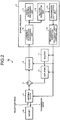
- FIG. 2 is a block diagram illustrating an example configuration of the radar device according to the present embodiment.
- a radar device 50 includes an exciter 1, an amplifier 2, a circulator 3, the antenna device 4, a receiver 8, and a signal processor 9.
- the signal processor 9 includes a coherent integration processing unit 10, a target detection processing unit 11, a clutter observation unit 12, a transmission duty control unit 13, and a transmission-reception switching-timing control unit 14.
- the exciter 1 generates a pulse-modulated signal that becomes the source of a transmission wave 5.
- the amplifier 2 amplifies a signal generated by the exciter 1.
- the circulator 3 transmits a signal from the amplifier 2 to the antenna device 4 and transmits a signal received from the antenna device 4 to the receiver 8.
- the antenna device 4 irradiates the target 22 with a signal transmitted via the circulator 3 as the transmission wave 5.
- the transmission wave 5 is reflected by the target 22 and is received by the antenna device 4 as a reception wave 7.
- the reception wave 7 received by the antenna device 4 is transmitted to the receiver 8 via the circulator 3 as a reception signal.
- the receiver 8 includes a plurality of narrow band filters, an amplifier, and the like (not illustrated) to perform reception processing such as amplification and filtering using each of the narrow band filters.
- a radar signal having undergone reception processing is discriminated into a plurality of signals corresponding to the respective narrow band filters, and the signals are transmitted to the signal processor 9.
- the coherent integration processing unit 10 performs coherent integration processing on spectrums of the signals discriminated by the respective narrow band filters.
- the target detection processing unit 11 calculates the distance to the target 22, the relative velocity between the target 22 and the vehicle itself, the bearing of the target 22, and the like with respect to the signals having undergone coherent integration processing.
- the clutter observation unit 12 uses the signals having undergone the coherent integration processing to calculate the clutter reception power level (hereinafter, referred to as "clutter level"). At least one of the pieces of the clutter level information is transmitted to the transmission duty control unit 13.
- the transmission duty control unit 13 generates a signal for controlling the transmission duty that is a ratio between a radar-signal transmission time and a radar-signal transmission cycle (hereinafter, referred to as "transmission duty control signal") in accordance with the observed clutter level, and then the transmission duty control unit 13 transmits the generated signal to the transmission-reception switching-timing control unit 14.
- the transmission-reception switching-timing control unit 14 uses the transmission duty ratio related the information included in the transmission duty control signal to control the exciter 1, the amplifier 2, the antenna device 4, and the receiver 8 in such a manner that the transmission duty ratio of the radar transmission wave 23 becomes a desired transmission duty ratio.
- FIG. 3 is a flowchart illustrating the transmission duty control according to the present embodiment.
- FIG. 4 is a diagram illustrating a transmission-reception pattern that illustrates the transmission duty control according to the present embodiment.
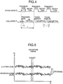
- FIG. 5 is an explanatory diagram illustrating how the clutter level varies under the transmission duty control.
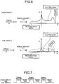
- FIG. 6 is an explanatory diagram illustrating how the reception environment changes under the transmission duty control according to the present embodiment.
- FIG. 7 is a diagram illustrating a conventional transmission-reception pattern as a comparative example in which transmission duty control is not executed.
- FIG. 8 is an explanatory diagram illustrating a conventional reception environment in which transmission duty control is not executed.
- the radar device 50 detects and tracks a target (Step S101).
- the radar device 50 determines whether a target to be dealt with is a tail aspect target or a head aspect target (Step S102).
- the determination of whether the target is a tail aspect target or a head aspect target is performed on the basis of the magnitude relation between a detection-target Doppler frequency and a Doppler frequency generated by the missile velocity of the vehicle itself.
- the radar device 50 determines that the target is a head aspect target.
- the radar device 50 determines that the target is a tail aspect target.
- Step S103 When it is determined that the target is a tail aspect target at Step S102, the processing flow shifts to Step S103.
- the radar device 50 identifies the currently-set transmission duty ratio (Step S103). When the set transmission duty ratio is "High”, the radar device 50 sets the transmission duty ratio to "Low” (Step S104). When the set transmission duty ratio is "Low”, the transmission duty ratio remains “Low” and the processing flow is continued from Step S101.
- Step S105 when it is determined that the target is a head aspect target at Step S102, the processing flow shifts to Step S105.
- the radar device 50 identifies the currently-set transmission duty ratio (Step S105). When the set transmission duty ratio is "Low”, the radar device 50 sets the transmission duty ratio to "High” (Step S106). When the set transmission duty ratio is "High”, the transmission duty ratio remains “High” and the processing flow is continued from Step S101.
- a state of the transmission duty control at this time is illustrated in FIG. 4 .
- the transmission duty ratio ( ⁇ 1/T) for a head aspect target is set greater than the transmission duty ratio ( ⁇ 2/T) for a tail aspect target.
- the clutter level is observed in the HPRF system under a clutter environment.
- the transmission duty ratio is low, the transmission power per cycle is reduced.
- the clutter level is decreased over the entire frequency range, as illustrated in FIG. 5 .
- the radar device 50 according to the present embodiment actively utilizes such a phenomenon as described above. Specifically, the radar device 50 constantly observes the clutter level. When the clutter level from a tail aspect target is higher than a receiver noise level, the radar device 50 controls the transmission duty ratio so as to decrease it such that the clutter level becomes equal to or closer to the receiver noise level in order to decrease the average transmission power. Power saving is thereby achieved while still ensuring appropriate detection performance under a clutter environment.
- FIG. 6 illustrates the relation of a reception power Pr relative to a Doppler frequency fd.
- the relative velocity between the vehicle itself and the target is greater than the relative velocity between the vehicle itself and the clutter, they can be separated in the Doppler frequency fd, which can prevent detection of the target from being affected by the clutter.
- a reception environment for a tail aspect target is illustrated in the lower section of FIG. 6 .
- the transmission duty ratio is controlled such that it becomes lower, the target reception power level is reduced.
- the relative velocity is lower, and thus a target detection area in a frequency domain falls within a clutter area.
- the transmission duty ratio is lower, the clutter level is also reduced.
- the transmission duty ratio is controlled such that the clutter level becomes equal to or closer to the receiver noise level so that the target can be detected as long as its reception power level is not buried in the receiver noise level. Therefore, under the transmission duty control according to the present embodiment, it is possible to ensure a certain level or higher of detection performance and tracking performance of a tail aspect target.
- FIGS. 7 and 8 illustrate a conventional transmission-reception pattern and a reception environment as a comparative example in which transmission duty control is not executed.
- the relative velocity between a vehicle itself and a target can be separated in the Doppler frequency fd.
- the relative velocity between a vehicle itself and a target can be separated in the Doppler frequency fd.
- the target cannot be detected, and thus extension of a detectable distance and improvement in the tracking performance cannot be achieved.
- the radar device constantly observes the clutter level in an HPRF system under a clutter environment. Simultaneously, the radar device determines whether a target to be dealt with is a tail aspect target or a head aspect target. When the target to be dealt with is determined to be a tail aspect target, the radar device controls the transmission duty ratio so that it is decreased such that the clutter level becomes equal to or closer to the receiver noise level.
- the radar device controls the transmission duty ratio so that it is decreased such that the clutter level becomes equal to or closer to the receiver noise level.
- the respective processing units described here are the coherent integration processing unit 10, the target detection processing unit 11, the clutter observation unit 12, the transmission duty control unit 13, and the transmission-reception switching-timing control unit 14, all of which are illustrated in FIG. 2 .
- the signal processor 9 can be configured to include a Central Processing Unit (CPU) 100 that performs calculation, a memory 110 that stores therein programs to be read by the CPU 100, and an interface 120 that inputs and outputs a signal, as illustrated in FIG. 9 .
- the CPU 100 can be a device referred to as an arithmetic device, a microprocessor, a microcomputer, a processor, a Digital Signal Processor (DSP), and the like.
- DSP Digital Signal Processor
- the memory 110 corresponds to, for example, a nonvolatile or volatile semiconductor memory such as a Random Access Memory (RAM), a Read Only Memory (ROM), a flash memory, an Erasable Programmable ROM (EPROM), or an Electrically EPROM (EEPROM).
- RAM Random Access Memory
- ROM Read Only Memory
- EPROM Erasable Programmable ROM
- EEPROM Electrically EPROM
- programs to implement the functions of the respective processing units in the signal processor 9 are stored in the memory 110.
- the CPU 100 transmits and receives necessary information through the interface 120 in order to perform various types of computation processing and control processing, which have been described in the present embodiment.
- the CPU 100 and the memory 110 illustrated in FIG. 9 are replaced by a processing circuit.
- the processing circuit corresponds to, for example, a single circuit, a composite circuit, a programmed processor, a parallel-programmed processor, an Application Specific Integrated Circuit (ASIC), a Field-Programmable Gate Array (FPGA), or a combination thereof.
- ASIC Application Specific Integrated Circuit
- FPGA Field-Programmable Gate Array
- the radar device observes the clutter level by using a signal obtained by performing coherent integration processing on a reception signal from the receiver, and it then controls the transmission duty ratio such that the observed clutter level becomes equal to or closer to a receiver noise level.
- the transmission power capacity and the amount of generated heat can be reduced. Consequently, it is possible to downsize a battery for transmission and simplify the thermal structure.
- the radar device determines whether a target to be dealt with is a tail aspect target or a head aspect target.
- the radar device reduces the transmission duty ratio compared to when the target is a head aspect target.
- the transmission power capacity and the amount of generated heat can be reduced. It is possible that the size and performance of the radar device, such as the total amount of heat generated in the radio seeker during radio-wave transmission and the battery capacity needed for radio-wave transmission, does not become a constraint on dealing with a tail aspect target. Further, it is possible to slightly extend the detectable distance of a tail aspect target.
Landscapes
- Engineering & Computer Science (AREA)
- Radar, Positioning & Navigation (AREA)
- Remote Sensing (AREA)
- General Engineering & Computer Science (AREA)
- Physics & Mathematics (AREA)
- Chemical & Material Sciences (AREA)
- Combustion & Propulsion (AREA)
- Computer Networks & Wireless Communication (AREA)
- General Physics & Mathematics (AREA)
- Electromagnetism (AREA)
- Aviation & Aerospace Engineering (AREA)
- Radar Systems Or Details Thereof (AREA)
- Aiming, Guidance, Guns With A Light Source, Armor, Camouflage, And Targets (AREA)
Abstract
Description
- The present invention relates to an active homing radar device that uses a radar wave generated thereby and to a method of processing radar signals.
- Guidance (particularly, terminal guidance) systems for flying vehicles such as missiles are mainly active homing systems that use radar waves generated by the systems themselves. An active homing system is disclosed in detail in Patent Literature 1 listed below.
- Japanese Patent Application Laid-open No.
H9-236400 - Improvement in the average transmission power is an effective method of extending detection distances, and thus a High Pulse Repetition Frequency system (hereinafter, "HPRF system") with a high duty ratio and high average power transmission is especially effective as an active homing radar device to handle an approaching target (also referred to as "head aspect target", which is hereinafter used in the specification). Therefore, HPRF systems are often employed for this purpose.
- However, a missile in which an active homing radio seeker is mounted needs to deal, not only with a head aspect target, but also with a departing target (also referred to as "tail aspect target", which is hereinafter used in the specification). For the tail aspect target, because the relative approaching velocity between the target and the missile is lower when compared to the head aspect target, a longer time is required for the missile to collide with the target. However, when the time until collision becomes long, the time required to irradiate a radio wave, i.e., the radar-wave transmission time, also becomes longer. Thus, the radar-wave transmission time is often determined by the time required until the collision. Furthermore, a longer radar-wave transmission time leads to a need for increased radar-wave transmission battery capacity and thus an increase in the battery size. Further, a cooling mechanism to cope with an increase in the amount of heat generated by the transmission system of the radio seeker is required. As a result, transmission of a radar wave over a longer period of time has become one of the causes of an increase in the size of radio seekers. In view of the overall missile performance, an increase in the size of the radio seeker leads to disadvantages such as degradation in the flying performance caused by, for example, a less amount of fuel that is loaded. In other words, the size and performance of the radar device, including such as the total amount of heat generated by the radio seeker during radio-wave transmission and the battery capacity needed for radio-wave transmission, largely depend on constraints imposed for dealing with a tail aspect target.
- The objective of the present invention, in view of the above problems, is to provide a radar device that can handle both a head aspect target and a tail aspect target without degrading the detection performance and tracking performance of the head aspect target and that can also minimize an increase in the device size and performance.
- In order to solve the above problems and achieve the objective, the present invention provides an active homing radar device that uses a radar wave generated thereby, the radar device comprising: an antenna device to irradiate a target with the radar wave; a receiver to receive, via the antenna device, a reflected wave from the target; and a signal processor to perform coherent integration processing on a reception signal from the receiver, to observe the clutter level by using a signal on which the coherent integration processing has been performed, and to control the transmission duty ratio such that the clutter level observed becomes equal to or closer to the receiver noise level.
- According to the present invention, there is an effect where it is possible to handle both a head aspect target and a tail aspect target without degrading the detection performance and tracking performance of the head aspect target and to also minimize an increase in the device size and performance.
-
-
FIG. 1 is an explanatory diagram explaining the concept of an active homing system. -
FIG. 2 is a block diagram illustrating an example configuration of a radar device according to an embodiment of the present invention. -
FIG. 3 is a flowchart explaining transmission duty control according to the embodiment. -
FIG. 4 is a diagram illustrating a transmission-reception pattern that explains transmission duty control according to the embodiment. -
FIG. 5 is an explanatory diagram illustrating how the clutter level varies under transmission duty control. -
FIG. 6 is an explanatory diagram illustrating how the reception environment changes under transmission duty control according to the embodiment. -
FIG. 7 is a diagram illustrating a conventional transmission-reception pattern as a comparative example in which transmission duty control is not executed. -
FIG. 8 is an explanatory diagram illustrating a conventional reception environment in which transmission duty control is not executed. -
FIG. 9 is a diagram illustrating an example of a hardware configuration in which respective processing units of a signal processor are implemented by software according to the embodiment. - A radar device and a processing method of a radar signal according to an embodiment of the present invention will be described in detail below with reference to the accompanying drawings. The present invention is not limited to the embodiment.
- First, the concept of an active homing system is described with reference to
FIG. 1. FIG. 1 is an explanatory diagram for explaining the concept of the active homing system. - In
FIG. 1 , anantenna device 4 and a control device (not illustrated) are mounted in aflying vehicle 20. Theflying vehicle 20 flies at a velocity Vm in an angular direction at an angle of attack "a" relative to anaxial direction 26 of theflying vehicle 20 in order to intercept atarget 22. Theflying vehicle 20 transmits aradar transmission wave 23 from theantenna device 4 toward thetarget 22 flying at a velocity Vt, and it receives a reflected wave from thetarget 22 as aradar reception wave 24. - The control device in the
flying vehicle 20 calculates a visual line angle "b" from an angular difference between apreset reference line 25 and avisual line 27 that is the direction from which theantenna device 4 receives theradar reception wave 24. The control device then calculates the rate of change in the visual line angle "b" from a change in the angular difference over time. The control device then calculates an aspect angle θ from the angular difference between thevisual line 27 and the traveling direction of thetarget 22. The control device then calculates an antenna swing angle λ in theantenna device 4 from the angular difference between theaxial direction 26 and thevisual line 27. The control device then calculates the relative velocity between thetarget 22 and theflying vehicle 20 by using information on the frequency difference between theradar transmission wave 23 transmitted from theantenna device 4 and theradar reception wave 24 received by theantenna device 4, i.e., by using a Doppler frequency. The control device then calculates the distance between thetarget 22 and theflying vehicle 20 by using information on the time difference between when theantenna device 4 transmits theradar transmission wave 23 and when theantenna device 4 receives theradar reception wave 24. - The
flying vehicle 20 collides with thetarget 22 at acollision point 28, which is the intersection of the traveling direction of thetarget 22 and theflying vehicle 20. Thus, the control device in theflying vehicle 20 corrects the velocity Vm of theflying vehicle 20 in accordance with the behavior of thetarget 22, and it generates an acceleration Am in a direction perpendicular to the traveling direction of theflying vehicle 20 so as to continuously correct the path of theflying vehicle 20 in order to intercept thetarget 22. - Next, a radar device according to the present embodiment is described.
FIG. 2 is a block diagram illustrating an example configuration of the radar device according to the present embodiment. - As illustrated im
FIG. 2 , aradar device 50 according to the present embodiment includes an exciter 1, an amplifier 2, a circulator 3, theantenna device 4, a receiver 8, and a signal processor 9. The signal processor 9 includes a coherentintegration processing unit 10, a targetdetection processing unit 11, aclutter observation unit 12, a transmissionduty control unit 13, and a transmission-reception switching-timing control unit 14. - The exciter 1 generates a pulse-modulated signal that becomes the source of a
transmission wave 5. The amplifier 2 amplifies a signal generated by the exciter 1. The circulator 3 transmits a signal from the amplifier 2 to theantenna device 4 and transmits a signal received from theantenna device 4 to the receiver 8. Theantenna device 4 irradiates thetarget 22 with a signal transmitted via the circulator 3 as thetransmission wave 5. - The
transmission wave 5 is reflected by thetarget 22 and is received by theantenna device 4 as areception wave 7. Thereception wave 7 received by theantenna device 4 is transmitted to the receiver 8 via the circulator 3 as a reception signal. The receiver 8 includes a plurality of narrow band filters, an amplifier, and the like (not illustrated) to perform reception processing such as amplification and filtering using each of the narrow band filters. - In the receiver 8, a radar signal having undergone reception processing is discriminated into a plurality of signals corresponding to the respective narrow band filters, and the signals are transmitted to the signal processor 9. The coherent
integration processing unit 10 performs coherent integration processing on spectrums of the signals discriminated by the respective narrow band filters. The targetdetection processing unit 11 calculates the distance to thetarget 22, the relative velocity between thetarget 22 and the vehicle itself, the bearing of thetarget 22, and the like with respect to the signals having undergone coherent integration processing. Theclutter observation unit 12 uses the signals having undergone the coherent integration processing to calculate the clutter reception power level (hereinafter, referred to as "clutter level"). At least one of the pieces of the clutter level information is transmitted to the transmissionduty control unit 13. The transmissionduty control unit 13 generates a signal for controlling the transmission duty that is a ratio between a radar-signal transmission time and a radar-signal transmission cycle (hereinafter, referred to as "transmission duty control signal") in accordance with the observed clutter level, and then the transmissionduty control unit 13 transmits the generated signal to the transmission-reception switching-timing control unit 14. The transmission-reception switching-timing control unit 14 uses the transmission duty ratio related the information included in the transmission duty control signal to control the exciter 1, the amplifier 2, theantenna device 4, and the receiver 8 in such a manner that the transmission duty ratio of theradar transmission wave 23 becomes a desired transmission duty ratio. - In the above descriptions, explanations of processing to calculate control information, steering information, and the like for guiding the flying
vehicle 20 to thetarget 22 are omitted. However, it is fully understood that a processing unit and a control unit that perform the above calculation processing are configured within the flyingvehicle 20. - Next, an operation of the radar device according to the present embodiment is described with reference to
FIGS. 1 to 8 as appropriate.FIG. 3 is a flowchart illustrating the transmission duty control according to the present embodiment.FIG. 4 is a diagram illustrating a transmission-reception pattern that illustrates the transmission duty control according to the present embodiment.FIG. 5 is an explanatory diagram illustrating how the clutter level varies under the transmission duty control.FIG. 6 is an explanatory diagram illustrating how the reception environment changes under the transmission duty control according to the present embodiment.FIG. 7 is a diagram illustrating a conventional transmission-reception pattern as a comparative example in which transmission duty control is not executed.FIG. 8 is an explanatory diagram illustrating a conventional reception environment in which transmission duty control is not executed. - In
FIG. 3 , theradar device 50 detects and tracks a target (Step S101). Theradar device 50 determines whether a target to be dealt with is a tail aspect target or a head aspect target (Step S102). The determination of whether the target is a tail aspect target or a head aspect target is performed on the basis of the magnitude relation between a detection-target Doppler frequency and a Doppler frequency generated by the missile velocity of the vehicle itself. When the component of the velocity Vt in the direction of thevisual line 27 approaches the flyingvehicle 20, theradar device 50 determines that the target is a head aspect target. When the component of the velocity Vt in the direction of thevisual line 27 departs from the flyingvehicle 20, theradar device 50 determines that the target is a tail aspect target. - When it is determined that the target is a tail aspect target at Step S102, the processing flow shifts to Step S103. The
radar device 50 identifies the currently-set transmission duty ratio (Step S103). When the set transmission duty ratio is "High", theradar device 50 sets the transmission duty ratio to "Low" (Step S104). When the set transmission duty ratio is "Low", the transmission duty ratio remains "Low" and the processing flow is continued from Step S101. - In contrast, when it is determined that the target is a head aspect target at Step S102, the processing flow shifts to Step S105. The
radar device 50 identifies the currently-set transmission duty ratio (Step S105). When the set transmission duty ratio is "Low", theradar device 50 sets the transmission duty ratio to "High" (Step S106). When the set transmission duty ratio is "High", the transmission duty ratio remains "High" and the processing flow is continued from Step S101. - A state of the transmission duty control at this time is illustrated in
FIG. 4 . The transmission duty ratio (τ1/T) for a head aspect target is set greater than the transmission duty ratio (τ2/T) for a tail aspect target. - The clutter level is observed in the HPRF system under a clutter environment. When the transmission duty ratio is low, the transmission power per cycle is reduced. Thus, the clutter level is decreased over the entire frequency range, as illustrated in
FIG. 5 . Theradar device 50 according to the present embodiment actively utilizes such a phenomenon as described above. Specifically, theradar device 50 constantly observes the clutter level. When the clutter level from a tail aspect target is higher than a receiver noise level, theradar device 50 controls the transmission duty ratio so as to decrease it such that the clutter level becomes equal to or closer to the receiver noise level in order to decrease the average transmission power. Power saving is thereby achieved while still ensuring appropriate detection performance under a clutter environment. - A reception environment for a head aspect target is illustrated in the upper section of
FIG. 6. FIG. 6 illustrates the relation of a reception power Pr relative to a Doppler frequency fd. As illustrated inFIG. 6 , in the HPRF system, as the relative velocity between the vehicle itself and the target is greater than the relative velocity between the vehicle itself and the clutter, they can be separated in the Doppler frequency fd,, which can prevent detection of the target from being affected by the clutter. - In contrast, a reception environment for a tail aspect target is illustrated in the lower section of
FIG. 6 . In the case of a tail aspect target, as the transmission duty ratio is controlled such that it becomes lower, the target reception power level is reduced. Further, in the case of the tail aspect target, the relative velocity is lower, and thus a target detection area in a frequency domain falls within a clutter area. However, because the transmission duty ratio is lower, the clutter level is also reduced. With the transmission duty control according to the present embodiment, the transmission duty ratio is controlled such that the clutter level becomes equal to or closer to the receiver noise level so that the target can be detected as long as its reception power level is not buried in the receiver noise level. Therefore, under the transmission duty control according to the present embodiment, it is possible to ensure a certain level or higher of detection performance and tracking performance of a tail aspect target. -
FIGS. 7 and8 illustrate a conventional transmission-reception pattern and a reception environment as a comparative example in which transmission duty control is not executed. As illustrated in the upper section ofFIG. 8 , in the case of a head aspect target, the relative velocity between a vehicle itself and a target can be separated in the Doppler frequency fd. However, in the case of a tail aspect target, as there is clutter at the same level as the relative velocity between the vehicle itself and the target, there is a range in which the target cannot be detected, and thus extension of a detectable distance and improvement in the tracking performance cannot be achieved. - As described above, the radar device according to the present embodiment constantly observes the clutter level in an HPRF system under a clutter environment. Simultaneously, the radar device determines whether a target to be dealt with is a tail aspect target or a head aspect target. When the target to be dealt with is determined to be a tail aspect target, the radar device controls the transmission duty ratio so that it is decreased such that the clutter level becomes equal to or closer to the receiver noise level. Thus, it is possible to reduce the total amount of heat generated in the radio seeker during radio-wave transmission and to reduce the battery capacity and the like needed for the radio-wave transmission. With this configuration, at the time of dealing with a tail aspect target that requires a longer transmission time, the transmission power capacity and the amount of generated heat can be reduced. As a result, the radio-wave transmission battery is downsized and the thermal structure is simplified. As the transmission duty ratio is decreased, the reception area is increased. Thus, an effect of slightly extending the detectable distance is achieved.
- Finally, there is a supplementary description of the effect of extending the detectable distance. As a specific example, a case where the transmission duty is decreased from 1/3 to 1/12 is described. In this case, the average transmission power is reduced to 1/4. Consequently, the transmission power capacity and the amount of generated heat can also be reduced to 1/4 as compared to those of the conventional device. This makes it possible to downsize the device.
- When a transmission pulse width and a reception gate width are made identical to each other and the transmission pulse width is defined as "1", the number of reception gates M1 before the transmission duty ratio is changed becomes 2 (=3-1), which is obtained by subtracting the transmission pulse width "1" from the length per cycle "3". In contrast thereto, after the transmission duty ratio is changed, the number of reception gates M2 becomes 11 (=12-1), which is obtained by subtracting the transmission pulse width "1" from the length per cycle "12". Non Patent Literature "RADAR HANDBOOK SECOND EDITION" (Merrill I. Skolnik McGraw-Hill Publishing Company in 1990) shows in FIG. 16 (Loss factor for M contiguous range gate) that the average loss with an eclipse taken into account is improved by approximately 1.1 dB, which results in an effect of extending the detectable distance to a distance that is approximately 1.06 times longer.
- Finally, a hardware configuration of the signal processor 9 according to the present embodiment when its respective processing units are implemented by software is described with reference to
FIG. 9 . The respective processing units described here are the coherentintegration processing unit 10, the targetdetection processing unit 11, theclutter observation unit 12, the transmissionduty control unit 13, and the transmission-reception switching-timing control unit 14, all of which are illustrated inFIG. 2 . - In a case where functions of the respective processing units in the signal processor 9 are implemented by software, the signal processor 9 can be configured to include a Central Processing Unit (CPU) 100 that performs calculation, a
memory 110 that stores therein programs to be read by the CPU 100, and aninterface 120 that inputs and outputs a signal, as illustrated inFIG. 9 . The CPU 100 can be a device referred to as an arithmetic device, a microprocessor, a microcomputer, a processor, a Digital Signal Processor (DSP), and the like. Further, thememory 110 corresponds to, for example, a nonvolatile or volatile semiconductor memory such as a Random Access Memory (RAM), a Read Only Memory (ROM), a flash memory, an Erasable Programmable ROM (EPROM), or an Electrically EPROM (EEPROM). - Specifically, programs to implement the functions of the respective processing units in the signal processor 9 are stored in the
memory 110. The CPU 100 transmits and receives necessary information through theinterface 120 in order to perform various types of computation processing and control processing, which have been described in the present embodiment. - It is permissible that the CPU 100 and the
memory 110 illustrated inFIG. 9 are replaced by a processing circuit. The processing circuit corresponds to, for example, a single circuit, a composite circuit, a programmed processor, a parallel-programmed processor, an Application Specific Integrated Circuit (ASIC), a Field-Programmable Gate Array (FPGA), or a combination thereof. - As described above, the radar device according to the present embodiment observes the clutter level by using a signal obtained by performing coherent integration processing on a reception signal from the receiver, and it then controls the transmission duty ratio such that the observed clutter level becomes equal to or closer to a receiver noise level. Thus, at the time of dealing with a tail aspect target that requires a longer transmission time, the transmission power capacity and the amount of generated heat can be reduced. Consequently, it is possible to downsize a battery for transmission and simplify the thermal structure.
- The radar device according to the present embodiment determines whether a target to be dealt with is a tail aspect target or a head aspect target. When the target is a tail aspect target, the radar device reduces the transmission duty ratio compared to when the target is a head aspect target. Thus, at the time of dealing with a tail aspect target, which requires a longer transmission time, the transmission power capacity and the amount of generated heat can be reduced. It is possible that the size and performance of the radar device, such as the total amount of heat generated in the radio seeker during radio-wave transmission and the battery capacity needed for radio-wave transmission, does not become a constraint on dealing with a tail aspect target. Further, it is possible to slightly extend the detectable distance of a tail aspect target.
- The configurations described in the above embodiment are only examples of the content of the present invention. The configurations can be combined with other well-known techniques, and a part of each configuration can be omitted or modified without departing from the scope of the present invention.
- 1 exciter, 2 amplifier, 3 circulator, 4 antenna device, 5, 23 transmission wave, 7, 24 reception wave, 8 receiver, 9 signal processor, 10 coherent integration processing unit, 11 target detection processing unit, 12 clutter observation unit, 13 transmission duty control unit, 14 transmission-reception switching-timing control unit, 20 flying vehicle, 22 target, 25 reference line, 26 axial direction, 27 visual line, 28 collision point, 50 radar device, 110 memory, 120 interface.
Claims (3)
- An active homing radar device using a radar wave generated thereby, the radar device comprising:an antenna device to irradiate a target with the radar wave;a receiver to receive a reflected wave from the target through the antenna device; anda signal processorto perform coherent integration processing on a reception signal from the receiver,to observe a clutter level by using a signal on which the coherent integration processing has been performed, andto control a transmission duty ratio such that a clutter level observed becomes equal to or closer to a receiver noise level.
- The radar device according to claim 1, wherein
the radar device determines whether a target to be handled is a tail aspect target or a head aspect target, and
when the target is a tail aspect target, the radar device reduces the transmission duty ratio compared to when the target is a head aspect target. - A processing method of a radar signal transmitted and received in an active homing radar device, the processing method comprising:a first step of receiving a reflected wave from a target;a second step of performing coherent integration processing on a signal received at the first step;a third step of observing a clutter level by using a signal on which the coherent integration processing has been performed at the second step;a fourth step of determining whether the target to be handled is a tail aspect target or a head aspect target; anda fifth step of controlling a transmission duty ratio such that the clutter level observed at the third step becomes equal to or closer to a receiver noise level when the target to be handled is determined to be a tail aspect target at the fourth step.
Applications Claiming Priority (1)
| Application Number | Priority Date | Filing Date | Title |
|---|---|---|---|
| PCT/JP2016/057463 WO2017154154A1 (en) | 2016-03-09 | 2016-03-09 | Radar device and radar signal processing method |
Publications (3)
| Publication Number | Publication Date |
|---|---|
| EP3428676A1 true EP3428676A1 (en) | 2019-01-16 |
| EP3428676A4 EP3428676A4 (en) | 2019-02-20 |
| EP3428676B1 EP3428676B1 (en) | 2019-12-18 |
Family
ID=59790268
Family Applications (1)
| Application Number | Title | Priority Date | Filing Date |
|---|---|---|---|
| EP16893484.2A Active EP3428676B1 (en) | 2016-03-09 | 2016-03-09 | Radar device and radar signal processing method |
Country Status (3)
| Country | Link |
|---|---|
| EP (1) | EP3428676B1 (en) |
| JP (1) | JP6509426B2 (en) |
| WO (1) | WO2017154154A1 (en) |
Cited By (1)
| Publication number | Priority date | Publication date | Assignee | Title |
|---|---|---|---|---|
| EP3869146A1 (en) * | 2020-02-21 | 2021-08-25 | Diehl Defence GmbH & Co. KG | Control method for a missile radar sensor of a missile, missile control unit and missile |
Families Citing this family (1)
| Publication number | Priority date | Publication date | Assignee | Title |
|---|---|---|---|---|
| JP2024116490A (en) * | 2023-02-16 | 2024-08-28 | 三菱電機株式会社 | Guidance device and guidance method |
Family Cites Families (4)
| Publication number | Priority date | Publication date | Assignee | Title |
|---|---|---|---|---|
| JPS5842984A (en) * | 1981-09-08 | 1983-03-12 | Mitsubishi Electric Corp | Radar device |
| JPS5896264A (en) * | 1981-12-03 | 1983-06-08 | Mitsubishi Electric Corp | Tracking device for doppler frequency |
| US7379014B1 (en) * | 2004-09-15 | 2008-05-27 | Rockwell Collins, Inc. | Taxi obstacle detecting radar |
| JP4994419B2 (en) * | 2009-04-21 | 2012-08-08 | 三菱電機株式会社 | In-vehicle radar system |
-
2016
- 2016-03-09 EP EP16893484.2A patent/EP3428676B1/en active Active
- 2016-03-09 JP JP2018503931A patent/JP6509426B2/en active Active
- 2016-03-09 WO PCT/JP2016/057463 patent/WO2017154154A1/en not_active Ceased
Cited By (2)
| Publication number | Priority date | Publication date | Assignee | Title |
|---|---|---|---|---|
| EP3869146A1 (en) * | 2020-02-21 | 2021-08-25 | Diehl Defence GmbH & Co. KG | Control method for a missile radar sensor of a missile, missile control unit and missile |
| US12241725B2 (en) | 2020-02-21 | 2025-03-04 | Diehl Defence Gmbh & Co. Kg | Control method for a missile radar sensor of a missile, missile control unit and missile |
Also Published As
| Publication number | Publication date |
|---|---|
| WO2017154154A1 (en) | 2017-09-14 |
| EP3428676A4 (en) | 2019-02-20 |
| EP3428676B1 (en) | 2019-12-18 |
| JP6509426B2 (en) | 2019-05-08 |
| JPWO2017154154A1 (en) | 2018-07-19 |
Similar Documents
| Publication | Publication Date | Title |
|---|---|---|
| US8803731B2 (en) | Target-tracking radar and method for responding to fluctuations in target SNR | |
| US10613196B2 (en) | Apparatus for processing signals of radar and method for processing signals thereof | |
| JP4265803B2 (en) | Radar system | |
| US10823846B2 (en) | Object detection method and object detection device | |
| US20160154103A1 (en) | Radar device and signal processing method | |
| US20160084942A1 (en) | Target detection apparatus and vehicle control system | |
| US20130021195A1 (en) | Projectile detection system | |
| EP3588135B1 (en) | Method of determining an alignment error of an antenna and vehicle with an antenna and a detection device | |
| US20150234041A1 (en) | Radar apparatus | |
| EP3428676B1 (en) | Radar device and radar signal processing method | |
| KR20160081507A (en) | Vehicle radar system | |
| JP2011226796A (en) | Radar device | |
| JP6789671B2 (en) | Radar device and its radar signal processing method | |
| CN104483667A (en) | Vehicle-mounted radar device | |
| JP6350229B2 (en) | Guidance device | |
| KR101454297B1 (en) | System and method for intercepting missile using high range resolution fmicw | |
| US10520585B2 (en) | Radar device and signal processing method | |
| AU2020203605B2 (en) | Improvements relating to monopulse radar apparatus | |
| JP2005181237A (en) | Radar equipment | |
| US20240085521A1 (en) | Object detection device | |
| US20240329196A1 (en) | Apparatus for and method of detection target | |
| JPH11166799A (en) | Guided flying vehicle system | |
| JPH08110200A (en) | Active proximity fuze | |
| Amenabar | Semi-Empirical Approach for Missile Seeker Sizing | |
| JPH0791900A (en) | Active proximity fuze |
Legal Events
| Date | Code | Title | Description |
|---|---|---|---|
| STAA | Information on the status of an ep patent application or granted ep patent |
Free format text: STATUS: THE INTERNATIONAL PUBLICATION HAS BEEN MADE |
|
| PUAI | Public reference made under article 153(3) epc to a published international application that has entered the european phase |
Free format text: ORIGINAL CODE: 0009012 |
|
| STAA | Information on the status of an ep patent application or granted ep patent |
Free format text: STATUS: REQUEST FOR EXAMINATION WAS MADE |
|
| 17P | Request for examination filed |
Effective date: 20180830 |
|
| AK | Designated contracting states |
Kind code of ref document: A1 Designated state(s): AL AT BE BG CH CY CZ DE DK EE ES FI FR GB GR HR HU IE IS IT LI LT LU LV MC MK MT NL NO PL PT RO RS SE SI SK SM TR |
|
| AX | Request for extension of the european patent |
Extension state: BA ME |
|
| A4 | Supplementary search report drawn up and despatched |
Effective date: 20190123 |
|
| RIC1 | Information provided on ipc code assigned before grant |
Ipc: G01S 7/282 20060101AFI20190117BHEP Ipc: G01S 13/22 20060101ALI20190117BHEP Ipc: G01S 13/88 20060101ALI20190117BHEP Ipc: F42B 15/01 20060101ALI20190117BHEP Ipc: F41G 7/22 20060101ALI20190117BHEP |
|
| DAV | Request for validation of the european patent (deleted) | ||
| DAX | Request for extension of the european patent (deleted) | ||
| GRAP | Despatch of communication of intention to grant a patent |
Free format text: ORIGINAL CODE: EPIDOSNIGR1 |
|
| STAA | Information on the status of an ep patent application or granted ep patent |
Free format text: STATUS: GRANT OF PATENT IS INTENDED |
|
| INTG | Intention to grant announced |
Effective date: 20190704 |
|
| GRAS | Grant fee paid |
Free format text: ORIGINAL CODE: EPIDOSNIGR3 |
|
| GRAA | (expected) grant |
Free format text: ORIGINAL CODE: 0009210 |
|
| STAA | Information on the status of an ep patent application or granted ep patent |
Free format text: STATUS: THE PATENT HAS BEEN GRANTED |
|
| AK | Designated contracting states |
Kind code of ref document: B1 Designated state(s): AL AT BE BG CH CY CZ DE DK EE ES FI FR GB GR HR HU IE IS IT LI LT LU LV MC MK MT NL NO PL PT RO RS SE SI SK SM TR |
|
| REG | Reference to a national code |
Ref country code: CH Ref legal event code: EP |
|
| REG | Reference to a national code |
Ref country code: IE Ref legal event code: FG4D |
|
| REG | Reference to a national code |
Ref country code: DE Ref legal event code: R096 Ref document number: 602016026647 Country of ref document: DE |
|
| REG | Reference to a national code |
Ref country code: AT Ref legal event code: REF Ref document number: 1215235 Country of ref document: AT Kind code of ref document: T Effective date: 20200115 |
|
| REG | Reference to a national code |
Ref country code: NL Ref legal event code: MP Effective date: 20191218 |
|
| PG25 | Lapsed in a contracting state [announced via postgrant information from national office to epo] |
Ref country code: SE Free format text: LAPSE BECAUSE OF FAILURE TO SUBMIT A TRANSLATION OF THE DESCRIPTION OR TO PAY THE FEE WITHIN THE PRESCRIBED TIME-LIMIT Effective date: 20191218 Ref country code: GR Free format text: LAPSE BECAUSE OF FAILURE TO SUBMIT A TRANSLATION OF THE DESCRIPTION OR TO PAY THE FEE WITHIN THE PRESCRIBED TIME-LIMIT Effective date: 20200319 Ref country code: BG Free format text: LAPSE BECAUSE OF FAILURE TO SUBMIT A TRANSLATION OF THE DESCRIPTION OR TO PAY THE FEE WITHIN THE PRESCRIBED TIME-LIMIT Effective date: 20200318 Ref country code: NO Free format text: LAPSE BECAUSE OF FAILURE TO SUBMIT A TRANSLATION OF THE DESCRIPTION OR TO PAY THE FEE WITHIN THE PRESCRIBED TIME-LIMIT Effective date: 20200318 Ref country code: LV Free format text: LAPSE BECAUSE OF FAILURE TO SUBMIT A TRANSLATION OF THE DESCRIPTION OR TO PAY THE FEE WITHIN THE PRESCRIBED TIME-LIMIT Effective date: 20191218 Ref country code: FI Free format text: LAPSE BECAUSE OF FAILURE TO SUBMIT A TRANSLATION OF THE DESCRIPTION OR TO PAY THE FEE WITHIN THE PRESCRIBED TIME-LIMIT Effective date: 20191218 Ref country code: LT Free format text: LAPSE BECAUSE OF FAILURE TO SUBMIT A TRANSLATION OF THE DESCRIPTION OR TO PAY THE FEE WITHIN THE PRESCRIBED TIME-LIMIT Effective date: 20191218 |
|
| REG | Reference to a national code |
Ref country code: LT Ref legal event code: MG4D |
|
| PG25 | Lapsed in a contracting state [announced via postgrant information from national office to epo] |
Ref country code: RS Free format text: LAPSE BECAUSE OF FAILURE TO SUBMIT A TRANSLATION OF THE DESCRIPTION OR TO PAY THE FEE WITHIN THE PRESCRIBED TIME-LIMIT Effective date: 20191218 Ref country code: HR Free format text: LAPSE BECAUSE OF FAILURE TO SUBMIT A TRANSLATION OF THE DESCRIPTION OR TO PAY THE FEE WITHIN THE PRESCRIBED TIME-LIMIT Effective date: 20191218 |
|
| PG25 | Lapsed in a contracting state [announced via postgrant information from national office to epo] |
Ref country code: AL Free format text: LAPSE BECAUSE OF FAILURE TO SUBMIT A TRANSLATION OF THE DESCRIPTION OR TO PAY THE FEE WITHIN THE PRESCRIBED TIME-LIMIT Effective date: 20191218 |
|
| PG25 | Lapsed in a contracting state [announced via postgrant information from national office to epo] |
Ref country code: CZ Free format text: LAPSE BECAUSE OF FAILURE TO SUBMIT A TRANSLATION OF THE DESCRIPTION OR TO PAY THE FEE WITHIN THE PRESCRIBED TIME-LIMIT Effective date: 20191218 Ref country code: PT Free format text: LAPSE BECAUSE OF FAILURE TO SUBMIT A TRANSLATION OF THE DESCRIPTION OR TO PAY THE FEE WITHIN THE PRESCRIBED TIME-LIMIT Effective date: 20200513 Ref country code: RO Free format text: LAPSE BECAUSE OF FAILURE TO SUBMIT A TRANSLATION OF THE DESCRIPTION OR TO PAY THE FEE WITHIN THE PRESCRIBED TIME-LIMIT Effective date: 20191218 Ref country code: EE Free format text: LAPSE BECAUSE OF FAILURE TO SUBMIT A TRANSLATION OF THE DESCRIPTION OR TO PAY THE FEE WITHIN THE PRESCRIBED TIME-LIMIT Effective date: 20191218 Ref country code: NL Free format text: LAPSE BECAUSE OF FAILURE TO SUBMIT A TRANSLATION OF THE DESCRIPTION OR TO PAY THE FEE WITHIN THE PRESCRIBED TIME-LIMIT Effective date: 20191218 |
|
| PG25 | Lapsed in a contracting state [announced via postgrant information from national office to epo] |
Ref country code: IS Free format text: LAPSE BECAUSE OF FAILURE TO SUBMIT A TRANSLATION OF THE DESCRIPTION OR TO PAY THE FEE WITHIN THE PRESCRIBED TIME-LIMIT Effective date: 20200418 Ref country code: SK Free format text: LAPSE BECAUSE OF FAILURE TO SUBMIT A TRANSLATION OF THE DESCRIPTION OR TO PAY THE FEE WITHIN THE PRESCRIBED TIME-LIMIT Effective date: 20191218 Ref country code: SM Free format text: LAPSE BECAUSE OF FAILURE TO SUBMIT A TRANSLATION OF THE DESCRIPTION OR TO PAY THE FEE WITHIN THE PRESCRIBED TIME-LIMIT Effective date: 20191218 |
|
| REG | Reference to a national code |
Ref country code: DE Ref legal event code: R097 Ref document number: 602016026647 Country of ref document: DE |
|
| REG | Reference to a national code |
Ref country code: DE Ref legal event code: R119 Ref document number: 602016026647 Country of ref document: DE |
|
| REG | Reference to a national code |
Ref country code: AT Ref legal event code: MK05 Ref document number: 1215235 Country of ref document: AT Kind code of ref document: T Effective date: 20191218 |
|
| PLBE | No opposition filed within time limit |
Free format text: ORIGINAL CODE: 0009261 |
|
| STAA | Information on the status of an ep patent application or granted ep patent |
Free format text: STATUS: NO OPPOSITION FILED WITHIN TIME LIMIT |
|
| PG25 | Lapsed in a contracting state [announced via postgrant information from national office to epo] |
Ref country code: MC Free format text: LAPSE BECAUSE OF FAILURE TO SUBMIT A TRANSLATION OF THE DESCRIPTION OR TO PAY THE FEE WITHIN THE PRESCRIBED TIME-LIMIT Effective date: 20191218 Ref country code: DK Free format text: LAPSE BECAUSE OF FAILURE TO SUBMIT A TRANSLATION OF THE DESCRIPTION OR TO PAY THE FEE WITHIN THE PRESCRIBED TIME-LIMIT Effective date: 20191218 Ref country code: ES Free format text: LAPSE BECAUSE OF FAILURE TO SUBMIT A TRANSLATION OF THE DESCRIPTION OR TO PAY THE FEE WITHIN THE PRESCRIBED TIME-LIMIT Effective date: 20191218 |
|
| REG | Reference to a national code |
Ref country code: CH Ref legal event code: PL |
|
| 26N | No opposition filed |
Effective date: 20200921 |
|
| PG25 | Lapsed in a contracting state [announced via postgrant information from national office to epo] |
Ref country code: AT Free format text: LAPSE BECAUSE OF FAILURE TO SUBMIT A TRANSLATION OF THE DESCRIPTION OR TO PAY THE FEE WITHIN THE PRESCRIBED TIME-LIMIT Effective date: 20191218 Ref country code: SI Free format text: LAPSE BECAUSE OF FAILURE TO SUBMIT A TRANSLATION OF THE DESCRIPTION OR TO PAY THE FEE WITHIN THE PRESCRIBED TIME-LIMIT Effective date: 20191218 |
|
| REG | Reference to a national code |
Ref country code: BE Ref legal event code: MM Effective date: 20200331 |
|
| PG25 | Lapsed in a contracting state [announced via postgrant information from national office to epo] |
Ref country code: LU Free format text: LAPSE BECAUSE OF NON-PAYMENT OF DUE FEES Effective date: 20200309 |
|
| PG25 | Lapsed in a contracting state [announced via postgrant information from national office to epo] |
Ref country code: CH Free format text: LAPSE BECAUSE OF NON-PAYMENT OF DUE FEES Effective date: 20200331 Ref country code: LI Free format text: LAPSE BECAUSE OF NON-PAYMENT OF DUE FEES Effective date: 20200331 Ref country code: FR Free format text: LAPSE BECAUSE OF NON-PAYMENT OF DUE FEES Effective date: 20200331 Ref country code: IE Free format text: LAPSE BECAUSE OF NON-PAYMENT OF DUE FEES Effective date: 20200309 Ref country code: IT Free format text: LAPSE BECAUSE OF FAILURE TO SUBMIT A TRANSLATION OF THE DESCRIPTION OR TO PAY THE FEE WITHIN THE PRESCRIBED TIME-LIMIT Effective date: 20191218 Ref country code: DE Free format text: LAPSE BECAUSE OF NON-PAYMENT OF DUE FEES Effective date: 20201001 |
|
| PG25 | Lapsed in a contracting state [announced via postgrant information from national office to epo] |
Ref country code: PL Free format text: LAPSE BECAUSE OF FAILURE TO SUBMIT A TRANSLATION OF THE DESCRIPTION OR TO PAY THE FEE WITHIN THE PRESCRIBED TIME-LIMIT Effective date: 20191218 Ref country code: BE Free format text: LAPSE BECAUSE OF NON-PAYMENT OF DUE FEES Effective date: 20200331 |
|
| PG25 | Lapsed in a contracting state [announced via postgrant information from national office to epo] |
Ref country code: TR Free format text: LAPSE BECAUSE OF FAILURE TO SUBMIT A TRANSLATION OF THE DESCRIPTION OR TO PAY THE FEE WITHIN THE PRESCRIBED TIME-LIMIT Effective date: 20191218 Ref country code: MT Free format text: LAPSE BECAUSE OF FAILURE TO SUBMIT A TRANSLATION OF THE DESCRIPTION OR TO PAY THE FEE WITHIN THE PRESCRIBED TIME-LIMIT Effective date: 20191218 Ref country code: CY Free format text: LAPSE BECAUSE OF FAILURE TO SUBMIT A TRANSLATION OF THE DESCRIPTION OR TO PAY THE FEE WITHIN THE PRESCRIBED TIME-LIMIT Effective date: 20191218 |
|
| PG25 | Lapsed in a contracting state [announced via postgrant information from national office to epo] |
Ref country code: MK Free format text: LAPSE BECAUSE OF FAILURE TO SUBMIT A TRANSLATION OF THE DESCRIPTION OR TO PAY THE FEE WITHIN THE PRESCRIBED TIME-LIMIT Effective date: 20191218 |
|
| REG | Reference to a national code |
Ref country code: GB Ref legal event code: 746 Effective date: 20230103 |
|
| REG | Reference to a national code |
Ref country code: GB Ref legal event code: S47 Free format text: CANCELLATION OF ENTRY; APPLICATION FOR CANCELLATION OF ENTRY ON THE REGISTER OF A LICENCE OF RIGHT FILED ON 08 APRIL 2025 |
|
| PGFP | Annual fee paid to national office [announced via postgrant information from national office to epo] |
Ref country code: GB Payment date: 20260202 Year of fee payment: 11 |