EP3428569B1 - Modular holographic sighting system - Google Patents
Modular holographic sighting system Download PDFInfo
- Publication number
- EP3428569B1 EP3428569B1 EP18192418.4A EP18192418A EP3428569B1 EP 3428569 B1 EP3428569 B1 EP 3428569B1 EP 18192418 A EP18192418 A EP 18192418A EP 3428569 B1 EP3428569 B1 EP 3428569B1
- Authority
- EP
- European Patent Office
- Prior art keywords
- laser diode
- holographic
- light source
- sighting system
- alignment
- Prior art date
- Legal status (The legal status is an assumption and is not a legal conclusion. Google has not performed a legal analysis and makes no representation as to the accuracy of the status listed.)
- Active
Links
- 230000003287 optical effect Effects 0.000 claims description 30
- 230000003667 anti-reflective effect Effects 0.000 claims description 5
- 239000011521 glass Substances 0.000 claims description 5
- 230000009471 action Effects 0.000 claims description 3
- 230000005540 biological transmission Effects 0.000 claims description 3
- 238000000034 method Methods 0.000 description 9
- 230000004075 alteration Effects 0.000 description 8
- 238000004519 manufacturing process Methods 0.000 description 6
- 239000000047 product Substances 0.000 description 6
- 229920001971 elastomer Polymers 0.000 description 5
- XEEYBQQBJWHFJM-UHFFFAOYSA-N Iron Chemical compound [Fe] XEEYBQQBJWHFJM-UHFFFAOYSA-N 0.000 description 4
- 239000006185 dispersion Substances 0.000 description 4
- WHXSMMKQMYFTQS-UHFFFAOYSA-N Lithium Chemical compound [Li] WHXSMMKQMYFTQS-UHFFFAOYSA-N 0.000 description 2
- 239000003990 capacitor Substances 0.000 description 2
- 230000001010 compromised effect Effects 0.000 description 2
- 238000010586 diagram Methods 0.000 description 2
- 239000000806 elastomer Substances 0.000 description 2
- 238000005516 engineering process Methods 0.000 description 2
- 229910052742 iron Inorganic materials 0.000 description 2
- 229910052744 lithium Inorganic materials 0.000 description 2
- 230000033001 locomotion Effects 0.000 description 2
- 230000007246 mechanism Effects 0.000 description 2
- 230000008569 process Effects 0.000 description 2
- 230000004044 response Effects 0.000 description 2
- 238000007789 sealing Methods 0.000 description 2
- 230000002618 waking effect Effects 0.000 description 2
- HBBGRARXTFLTSG-UHFFFAOYSA-N Lithium ion Chemical compound [Li+] HBBGRARXTFLTSG-UHFFFAOYSA-N 0.000 description 1
- 230000008901 benefit Effects 0.000 description 1
- 238000004364 calculation method Methods 0.000 description 1
- 230000008859 change Effects 0.000 description 1
- 238000010276 construction Methods 0.000 description 1
- 230000001351 cycling effect Effects 0.000 description 1
- 230000001419 dependent effect Effects 0.000 description 1
- 238000005562 fading Methods 0.000 description 1
- 239000000835 fiber Substances 0.000 description 1
- 238000005286 illumination Methods 0.000 description 1
- 229910001416 lithium ion Inorganic materials 0.000 description 1
- 239000000463 material Substances 0.000 description 1
- 239000012466 permeate Substances 0.000 description 1
- 239000004033 plastic Substances 0.000 description 1
- 229910052709 silver Inorganic materials 0.000 description 1
- 239000004332 silver Substances 0.000 description 1
- -1 silver halide Chemical class 0.000 description 1
- 230000000087 stabilizing effect Effects 0.000 description 1
- 239000000758 substrate Substances 0.000 description 1
- 230000029305 taxis Effects 0.000 description 1
Images


Classifications
-
- G—PHYSICS
- G02—OPTICS
- G02B—OPTICAL ELEMENTS, SYSTEMS OR APPARATUS
- G02B23/00—Telescopes, e.g. binoculars; Periscopes; Instruments for viewing the inside of hollow bodies; Viewfinders; Optical aiming or sighting devices
- G02B23/14—Viewfinders
-
- F—MECHANICAL ENGINEERING; LIGHTING; HEATING; WEAPONS; BLASTING
- F41—WEAPONS
- F41G—WEAPON SIGHTS; AIMING
- F41G1/00—Sighting devices
- F41G1/06—Rearsights
- F41G1/14—Rearsights with lens
-
- F—MECHANICAL ENGINEERING; LIGHTING; HEATING; WEAPONS; BLASTING
- F41—WEAPONS
- F41G—WEAPON SIGHTS; AIMING
- F41G1/00—Sighting devices
- F41G1/32—Night sights, e.g. luminescent
- F41G1/34—Night sights, e.g. luminescent combined with light source, e.g. spot light
- F41G1/345—Night sights, e.g. luminescent combined with light source, e.g. spot light for illuminating the sights
-
- G—PHYSICS
- G02—OPTICS
- G02B—OPTICAL ELEMENTS, SYSTEMS OR APPARATUS
- G02B17/00—Systems with reflecting surfaces, with or without refracting elements
- G02B17/02—Catoptric systems, e.g. image erecting and reversing system
- G02B17/023—Catoptric systems, e.g. image erecting and reversing system for extending or folding an optical path, e.g. delay lines
-
- G—PHYSICS
- G02—OPTICS
- G02B—OPTICAL ELEMENTS, SYSTEMS OR APPARATUS
- G02B19/00—Condensers, e.g. light collectors or similar non-imaging optics
- G02B19/0033—Condensers, e.g. light collectors or similar non-imaging optics characterised by the use
- G02B19/0047—Condensers, e.g. light collectors or similar non-imaging optics characterised by the use for use with a light source
- G02B19/0052—Condensers, e.g. light collectors or similar non-imaging optics characterised by the use for use with a light source the light source comprising a laser diode
-
- G—PHYSICS
- G02—OPTICS
- G02B—OPTICAL ELEMENTS, SYSTEMS OR APPARATUS
- G02B27/00—Optical systems or apparatus not provided for by any of the groups G02B1/00 - G02B26/00, G02B30/00
- G02B27/0025—Optical systems or apparatus not provided for by any of the groups G02B1/00 - G02B26/00, G02B30/00 for optical correction, e.g. distorsion, aberration
-
- G—PHYSICS
- G02—OPTICS
- G02B—OPTICAL ELEMENTS, SYSTEMS OR APPARATUS
- G02B27/00—Optical systems or apparatus not provided for by any of the groups G02B1/00 - G02B26/00, G02B30/00
- G02B27/18—Optical systems or apparatus not provided for by any of the groups G02B1/00 - G02B26/00, G02B30/00 for optical projection, e.g. combination of mirror and condenser and objective
- G02B27/20—Optical systems or apparatus not provided for by any of the groups G02B1/00 - G02B26/00, G02B30/00 for optical projection, e.g. combination of mirror and condenser and objective for imaging minute objects, e.g. light-pointer
-
- G—PHYSICS
- G02—OPTICS
- G02B—OPTICAL ELEMENTS, SYSTEMS OR APPARATUS
- G02B27/00—Optical systems or apparatus not provided for by any of the groups G02B1/00 - G02B26/00, G02B30/00
- G02B27/42—Diffraction optics, i.e. systems including a diffractive element being designed for providing a diffractive effect
-
- G—PHYSICS
- G02—OPTICS
- G02B—OPTICAL ELEMENTS, SYSTEMS OR APPARATUS
- G02B5/00—Optical elements other than lenses
- G02B5/32—Holograms used as optical elements
Definitions
- the present invention in general relates to holographic sighting devices and in particular, to a holographic sighting system that is lightweight, waterproof, and modular and can be used on small firearms, bows, telescopes, and other applications where aiming is necessary.
- Red dot sighting systems -Reflex- such as those provided by AimPoint® solve many of the above difficulties, but are only able to project a single dot reticule pattern due to off-axis aberrations.
- US 2011/228366 A1 and US 2006/164704 A1 disclose sighting systems for a firearm.
- Holographic sighting systems such as described in U.S. Pat. No. 6,490,060 issued to Tai et al., have become the preferred solution for shooters requiring a high degree of accuracy with fast target acquisition.
- the Holographic Weapon Sight (HWS) manufactured by L3-Communications EOTech, Inc. was the first system to make use of holographic technology in order to project a full reticule pattern at or near the target plane creating a low parallax sighting solution that can be deployed quickly and in any lighting condition.
- EOTech holographic weapon sight (HWS) systems were also the first to make use of wavelength dispersion matching technology that allow laser diode illumination to be used over extended temperature ranges.
- HWS systems suffer from drawbacks related to their design and technique of manufacturing.
- Current HWS products utilize an internal mechanism to adjust reticule position, which alters the achromatic geometry of the system when aiming adjustments are made, thereby compromising the ability of the wavelength dispersion compensation elements to perform as intended. The result is that these sighting systems will perform differently when used in temperatures other than that of which they were initially aligned.
- current HWS products also suffer from reticule pattern distortion as a result of the mechanical stresses created from the internal adjustment mechanism.
- the wavelength stabilizing holographic optical element is bonded to a plastic flexible element, creating a system that is susceptible to wave front aberrations brought about by changes in temperature to the hologram and mounting substrate.
- the current HWS systems require higher intensities of laser diode power in order to maintain a desired reticule brightness and have average battery life spans far less than competing red-dot products.
- a holographic sighting system that is stable over a wide temperature range, maintains a battery life that is comparable to competing red-dot products, has a large, high aspect viewing window, occupies the minimum amount of rail space on a hand held weapon, and can be produced inexpensively and accurately in high volume.
- the solution is a holographic sighting system according to claim 1.
- a holographic sighting system includes an upper housing assembly enclosing a holographic optical element, an anti-reflective glass viewing window, a battery, and a laser diode light source driven by a microcontroller circuit configured to minimize the laser diode's current draw to maximize the battery life; and a lower housing assembly enclosing two dielectric folding mirrors, an on-axis collimating lens, and a high efficiency achromatizing holographic optical element.
- the holographic sighting system is mountable on at least one of; hand gun, rifle, crossbow or bow.
- the laser diode light source is a red diode laser light.
- the anti-reflective glass viewing window measures 1.4 X 1 inches (3.56 x 2.54 cm).
- the holographic sighting system has entirely fixed on-axis optical and holographic elements thereby providing the least amount of optical aberration over a wide temperature range.
- the system further includes fine grain holographic silver halide plates to improve diffraction efficiency and image resolution.
- the lower housing assembly of the holographic sighting system includes a modular base system that provides both vertical and horizontal aiming for the sighting system and eliminates the need for relative motion between optical elements.
- the modular base system is configured for attaching various sizes of the sighting system to a firearm while providing accurate windage and elevation adjustments.
- the holographic sighting system also includes a laser diode carrier for mounting the laser diode light, the laser diode carrier being attached to a flexible circuit that allows the laser diode to be adjusted via a set of alignment controllers connected between the lower housing assembly and to the laser diode carrier.
- the set of alignment controllers further include tensioning springs that provide an outward bias to the laser diode carrier that opposes the tightening action of the set of alignment controllers and eliminate hysteresis during focusing
- the Sight Body is sealed to the Optical Carrier by an injected elastomer after mechanical fixing of the two assembled components to provide a non-stressed seal that is not subject to the vagaries of assembly processes and withstands a wide range of temperature and pressure conditions while maintaining seal integrity.
- the present invention has utility as a lightweight holographic sighting system specifically designed to minimize optical aberrations common with earlier holographic sighting systems with a modular construction that is more economic and conducive to high volume production, in terms of complexity of required fixturing and availability of materials, than earlier systems.
- Embodiments of the invention provide a holographic sighting system that is lighter and more compact (shorter in length), while providing a larger field of view than existing systems that can be used on small hand guns, standard size firearms , bows, telescopes, and other devices without adding significant weight or space constraints.
- Embodiments of the inventive sighting system utilize an upper housing assembly containing a high efficiency holographic optical element, an anti-reflective glass viewing window, and a red diode laser light source driven by a high efficiency microcontroller circuit designed for increased battery life, and a lower housing assembly containing two dielectric folding mirrors, an on-axis collimating lens, and a high efficiency achromatizing holographic optical element.
- the inventive sighting system provides a larger viewing window than previous designs.
- a viewing window that measure 1.4 X 1 inches (3.56 x 2.54 cm) is provided.
- the inventive modular base system connects multiple sighting systems to a firearm while providing accurate windage and elevation adjustments.
- a modular base system provides both vertical and horizontal aiming for the sighting system eliminating the need for relative motion between optical components that leads to aberrations found in previous designs.
- the inventive holographic sighting system has entirely fixed on-axis optical and holographic elements thereby providing the least amount of optical aberration over a wide temperature range thereby maintaining a 1moa dot at the center of the reticule pattern.
- Embodiments of the inventive holographic sighting system utilize fine grain holographic plates in order to realize the highest possible diffraction efficiency and image resolution.
- rechargeable batteries for reducing weight and volume.
- rechargeable lithium ion type batteries used in portable electronic devices like cell phones, as well as conventional cell type batteries, such as button lithium cells, and double A size, that are used for availability and ease of replacement may be used in embodiments of the inventive sighting system.
- the inventive sighting system can be easily altered to accommodate multiple battery types.
- Embodiments of the inventive holographic sighting system obtain best in class battery life (as compared to current HWS systems on the market) by means of high efficiency optical components and electronics design.
- the housing is sealed by various methods; first of these methods is with a channeled elastomer seal that provides a non-stressed and fully encapsulated seal channel to protect the internal elements from the external atmosphere.
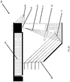
- embodiments of the inventive sighting system introduce a collimated laser light to a holographic wavelength compensation element over a surface area large enough to accommodate larger viewing windows 24, such as the 1.4 by 1 inch (3.56 x 2.54 cm) viewing window mentioned above as shown in FIG. 1A .
- This is accomplished by turning the laser beam 10 emitted by a laser diode module 32 twice through a distance of approximately 70 mm before being collimated by an aspheric surface.
- a laser diode 32 with a full width at half maximum (FWHM) energy density of 30° by 10° will cover a surface area of approximately 35 mm by 12 mm.
- the folding surfaces or mirrors (12, 14) are coated dielectrically to reflect the maximum energy at a wavelength of 650 nm at an a angle of 45 degrees.
- a section is cut from a collimating surface in some inventive embodiments.
- the collimated laser light 15 is incident on a "PRISM" 39 then holographic transmission grating 18.
- the diffracted light is then incident on the image hologram 26 and diffracted by the same amount. Because the dispersion of the two holograms are equal with opposite signs, there is no resulting deflection of the twice diffracted beam with changes in laser wavelength due to temperature.
- FIG. 1B is an embodiment of how simplified a holographic sighting system would become when temperature stable TO can laser diodes 32 are used.
- light 10 from the laser diode 32 is collimated by a lens 11 or a reflective element and passes through a holographic image 26 with no resulting aberrations due to temperature change.
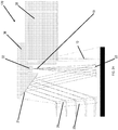
- FIGs. 2A-2H Optical lead lines and related elements for various embodiments of the present invention are provided with respect to FIGs. 2A-2H in which like reference numeral between depictions are intended to have like meanings.
- Separate sights are shown generally at 100, 110, 120, 130, 140, 150, 160, and 170 in FIGs. 2A-2H , respectively.
- a laser diode 32 emits a beam 10 that interacts with at least one lens element 16 and at least one mirror with a first mirror 12 and a second mirror 14 illustrated. It is appreciated that the type of lens elements, number or lens elements, orientation of lens elements, number of mirrors, and orientation of mirrors are all variables that are readily modified without departing from the present invention.
- a cover plate 28 serves to protect the optics from environmental exposure via the viewing window.
- the holographic image 26 is visible on a holographic plate positioned proximal to the cover plate 28.
- the holographic image 26 or other indicia is visible against a projection against a sighting field down range of the inventive sight as observed through transparent sighting window 13.
- an adjustable base 34 is present to adjust the relative position of the aforementioned optical elements.
- a power source 38 is provided to energize the laser diode 32 and electronics 36 associated with the present invention.
- the inventive sight 110 of FIG. 2B is also depicted include a holographic grating 21 and a reflecting collimator 23.
- a particular compact optical path and overall volume of sight 120 is noted compared to conventional holographic sights.
- FIG. 3 is a schematic diagram 200 for an embodiment of an inventive holographic sighting system which provides additional detail to the electronics subsystem 36 as shown in the embodiments of FIGs. 2A-2H .
- the operational schematic 200 can be subdivided into three major operational blocks.
- the first operational block represents power management via voltage regulator 202, and how all the circuits are powered.
- the second operational block is the microcontroller 206 and how the microcontroller is used to interface to external components.
- the third operational component is the control and settings of the laser diode 32 via laser controller 208.
- Powering embodiments of the inventive holographic sighting system is achieved through the use of a power source such as a battery or ultracapacitor.
- Power sources operative herein illustratively include battery formats of AAA, AA and button-type batteries; of various chemistries illustratively including alkaline, lithium, and various rechargeable batteries, each alone or with multiple batteries stacked in series.
- the battery power source 38 configuration provides a voltage which is then in turn used to power a switching voltage regulator 202.
- the voltage regulator 202 regulates the voltage to a required level for powering the microcontroller 206 as well as biasing the laser diode 32.
- the efficiency of the switching voltage regulator 202 is contributes to minimizing the current consumption of the system design of the inventive holographic sighting system. It is noted that emphasis is placed on using a low series resistance capacitor on the output of the regulator 202 which powers the rest of the electronics board 36.
- the voltage created from the switching voltage regulator 202 is supplied to an extremely low-power 8-bit microcontroller 206 that is used for a variety of tasks.
- the microcontroller 206 puts itself into a low-power state where only an external interrupt from the ON/Increase button found on the pushbutton controller 204 is capable of waking the microcontroller 206 up.
- the next state upon waking up the microcontroller 206 is to check the battery voltage powering the voltage regulator 202, and comparing the battery voltage to an internally generated voltage by the use of a comparator. If the battery voltage reads below an operating threshold, the microcontroller 206 flashes the laser diode 32 indicating a low-battery and then the microcontroller 206 proceeds to put itself back into a deep sleep.
- the microcontroller 206 Upon a successful wake-up, the microcontroller 206 is then used to generate a pulse-width modulated (PWM) signal used to set the current level of the laser diode 32, as well as a modulation signal used to pulse the laser light 10 at a higher frequency thus saving power from the high current consumption of the laser diode 32.
- PWM pulse-width modulated
- the high frequency modulation signals takes advantage of the fact that the laser diode 32 is slower in nature to reacting to fast changes which is commonly seen in fiber optic digital communications.
- the modulation frequency is set by an internal timer or an output of a system clock both generated by the microcontroller 206.
- the microcontroller 206 While in an operating state, the microcontroller 206 also handles interrupts created by the push-buttons on the pushbutton controller 204 which serves as an interface to a user of the inventive holographic sighting system. With the pushbutton controller 206, the user can turn on the holographic sighting system, increase optical intensity, decrease optical intensity, and turn off the system.
- the third operational component or subsystem of the electronics 36 is the control and settings of the laser diode 32 via laser controller 208.
- control of the laser diode 32 is accomplished through a pure analog design PWM and PFM techniques.
- the PWM signal is first put through a first order RC-filter (resistor capacitor filter). Doing this allows an average voltage to be fed into an op-amp configured as an integrator which is used to smooth out any abrupt variations that may occur from the modulation portion of the laser diode control 208.
- Optical feedback is provided back into the inverting leg of the op-amp, which allows the laser diode 32 to monitor itself and prevent the current consumption to get out of control and damage the laser diode 32.
- the feedback also helps to compensate for the small variations that may occur between laser diodes 32, as well as temperature changes when operating the inventive holographic sight.
- the optical feedback is obtained from a photodiode's current generation that is scaled appropriately by a resistor connecting the photodiode to ground. In essence, any current through the resistor creates a voltage according to Ohm's law and this is the voltage fed back into the op-amp. Careful selection of an op-amp with small input offset is also emphasized to minimize any inherited offset being that the voltage generated by the photodiode is extremely small and sensitive.
- BJT bipolar junction transistor
- the laser controller 208 is able to achieve higher optical powers, and yet not be penalized by the current consumption of the laser diode 32 through the use of a modulation circuit that controls a MOSFET transistor that modulates a path to ground of the laser diode 32.
- a modulation circuit that controls a MOSFET transistor that modulates a path to ground of the laser diode 32.
- a large resistor to ground is used to hold the laser 10 just below optical lasing. This gives the laser diode 32 a 'running start' whereas driving the laser diode 32 from a completely grounded signal taxes the system because of the current consumption needed for such a fast response.
- the MOSFET can be directly interfaced to the microcontroller 206 where only a voltage threshold is needed to trigger the MOSFET from an off to an on state.
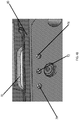
- FIGs. 4A-4C are a series of perspective views of the laser diode carrier 70 and adjustment controllers 76 or screws that allow for manual focus of the laser diode 32 according to embodiments of the invention.
- the laser diode 32 is mounted to a laser diode carrier 70 with the laser diode carrier 70 attached to a flexible circuit 78 that allows the laser diode 32 to be adjusted via the alignment controllers 76.
- the alignment controllers 76 attach the laser diode carrier 70 to the lower body component 80 of embodiments of the inventive holographic sighting system.
- the laser diode carrier 70 is spring loaded by tensioning springs 74 to eliminate hysteresis during focusing, which is performed on a focusing fixture (not shown).
- the tensioning springs 74 provide an outward bias to the laser diode carrier 70 that opposes the tightening action of the alignment controllers 76.
- FIG. 4C which is a top down cross-sectioned view of the laser diode carrier 70 of FIG. 4A , that shows the relationship between the alignment controllers 76 and the laser diode carrier 70. As shown in FIG.
- the laser diode 32 focus may be adjusted externally from the lower body component 80 with an alignment tool such as a hex head screwdriver, or other type of screwdriver or tool that can be inserted or engage into the alignment controllers.
- an alignment tool such as a hex head screwdriver, or other type of screwdriver or tool that can be inserted or engage into the alignment controllers.
- a user adjusts the laser diode carrier 70 focus orientation via the alignment controllers 76, and when a desired or correct focus is achieved the locking screw 72 is tightened, thereby fixing the laser diode carrier 70 and therefore the laser diode 32 in the focused position.
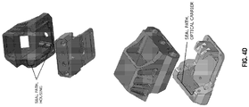
- the optical cavity seal is a closed cavity channel that provides a non-stressed seal that is applied to the assembled housing components after all settings and adjustments are completed. It is a consistent and reliable seal that is not subject to the vagaries of an assembly process.
- FIG. 4D is a consistent and reliable seal that is not subject to the vagaries of an assembly process.
Description
- The present invention in general relates to holographic sighting devices and in particular, to a holographic sighting system that is lightweight, waterproof, and modular and can be used on small firearms, bows, telescopes, and other applications where aiming is necessary.
- Multiple sighting methods for aiming firearms have been utilized for both commercial and military applications. The most basic, the iron sight, requires the shooter to align the rear sight, front sight, and the target while switching the eye's point of focus between the rear and front sight pattern and the target. The iron sight method, while reliable, can be difficult to learn and has multiple drawbacks including the rear and front sight obstructing the view of the target and complications arising from sub-optimal lighting conditions. Telescopic sights, while accurate, are not suited for situations where the target is moving, close quarter conditions, or if the shooter is mobile. Laser designator sights, where a laser beam illuminates the target can be difficult to use in certain lighting conditions and are unacceptable for military or self-defense applications where the shooters location must not be revealed. Red dot sighting systems -Reflex-, such as those provided by AimPoint® solve many of the above difficulties, but are only able to project a single dot reticule pattern due to off-axis aberrations.
US 2011/228366 A1 andUS 2006/164704 A1 disclose sighting systems for a firearm. - Holographic sighting systems, such as described in
U.S. Pat. No. 6,490,060 issued to Tai et al., have become the preferred solution for shooters requiring a high degree of accuracy with fast target acquisition. Specifically, the Holographic Weapon Sight (HWS) manufactured by L3-Communications EOTech, Inc. was the first system to make use of holographic technology in order to project a full reticule pattern at or near the target plane creating a low parallax sighting solution that can be deployed quickly and in any lighting condition. EOTech holographic weapon sight (HWS) systems were also the first to make use of wavelength dispersion matching technology that allow laser diode illumination to be used over extended temperature ranges. - However, currently available HWS systems suffer from drawbacks related to their design and technique of manufacturing. Current HWS products utilize an internal mechanism to adjust reticule position, which alters the achromatic geometry of the system when aiming adjustments are made, thereby compromising the ability of the wavelength dispersion compensation elements to perform as intended. The result is that these sighting systems will perform differently when used in temperatures other than that of which they were initially aligned. In addition to compromised wavelength dispersion matching, current HWS products also suffer from reticule pattern distortion as a result of the mechanical stresses created from the internal adjustment mechanism. The wavelength stabilizing holographic optical element is bonded to a plastic flexible element, creating a system that is susceptible to wave front aberrations brought about by changes in temperature to the hologram and mounting substrate. The resulting distortions can be observed as a "smudging" or increase in size of the dot element used for aiming. In addition, current HWS products use a standard o-ring and compressed flat rubber gasket system to isolate the holographic optical components from the outside environment. The effectiveness and reliability of an o-ring and compressed flat rubber gasket sealed HWS system is highly dependent on the repeatability of the manufacturing process. Any variability induced by workmanship and manufacturing methods affects the integrity and effectiveness of the seal over time. The flat rubber and o-ring sealing system is often compromised by the stresses caused from changing ambient temperature and pressure conditions, resulting in continued cycling of the housing cavity pressure, which tends make the flat gasket method of sealing failure prone. As a consequence, systems sealed in this manner tend to leak, allowing moisture to permeate the holographic elements resulting in fading of the reticule image.
- As a result, the current HWS systems require higher intensities of laser diode power in order to maintain a desired reticule brightness and have average battery life spans far less than competing red-dot products.
- Most current HWS products use an off axis reflection collimating element to prepare the light incident on the first holographic element. These reflection collimating elements require the precision removal of an off center section from a lens to be coated with a reflective element prior to their use in the HWS. However, inconsistencies in the production of this off center section introduce aberrations and increases production costs.
- Finally, current designs for HWS systems lack modularity, and minor changes to mounting systems, optical path, reticule patterns, and battery type require a complete re-design and re-tooling in order to implement the changes.
- Thus, there exists a need for a modular lightweight holographic sighting system that is stable over a wide temperature range, maintains a battery life that is comparable to competing red-dot products, has a large, high aspect viewing window, occupies the minimum amount of rail space on a hand held weapon, and can be produced inexpensively and accurately in high volume. The solution is a holographic sighting system according to
claim 1. - A holographic sighting system is provided that includes an upper housing assembly enclosing a holographic optical element, an anti-reflective glass viewing window, a battery, and a laser diode light source driven by a microcontroller circuit configured to minimize the laser diode's current draw to maximize the battery life; and a lower housing assembly enclosing two dielectric folding mirrors, an on-axis collimating lens, and a high efficiency achromatizing holographic optical element. The holographic sighting system is mountable on at least one of; hand gun, rifle, crossbow or bow. The laser diode light source is a red diode laser light. In a specific embodiment the anti-reflective glass viewing window measures 1.4
X 1 inches (3.56 x 2.54 cm). - The holographic sighting system has entirely fixed on-axis optical and holographic elements thereby providing the least amount of optical aberration over a wide temperature range. The system further includes fine grain holographic silver halide plates to improve diffraction efficiency and image resolution.
- The lower housing assembly of the holographic sighting system includes a modular base system that provides both vertical and horizontal aiming for the sighting system and eliminates the need for relative motion between optical elements. The modular base system is configured for attaching various sizes of the sighting system to a firearm while providing accurate windage and elevation adjustments.
- The holographic sighting system also includes a laser diode carrier for mounting the laser diode light, the laser diode carrier being attached to a flexible circuit that allows the laser diode to be adjusted via a set of alignment controllers connected between the lower housing assembly and to the laser diode carrier. The set of alignment controllers further include tensioning springs that provide an outward bias to the laser diode carrier that opposes the tightening action of the set of alignment controllers and eliminate hysteresis during focusing
- The Sight Body is sealed to the Optical Carrier by an injected elastomer after mechanical fixing of the two assembled components to provide a non-stressed seal that is not subject to the vagaries of assembly processes and withstands a wide range of temperature and pressure conditions while maintaining seal integrity.
- The present invention is further detailed with respect to the following drawings that are intended to show certain aspects of the present invention, but should not be construed as a limit on the practice of the present invention.
-
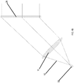
FIGs. 1A and1B illustrate the basic optical paths of the holographic sighting system according to embodiments of the invention; -
FIGs. 2A-2H are a series of cross-sectional views of various embodiments of the inventive holographic sighting system with various optical configurations for varying sized housing and power configurations; -
FIG. 3 is a schematic diagram of the electronics assembly for use in the holographic sighting system according to embodiments of the invention; and -
FIGs. 4A-4D are a series of perspective views of the laser diode carrier and adjustment screws that allow for focusing the laser diode according to embodiments of the invention. - The present invention has utility as a lightweight holographic sighting system specifically designed to minimize optical aberrations common with earlier holographic sighting systems with a modular construction that is more economic and conducive to high volume production, in terms of complexity of required fixturing and availability of materials, than earlier systems. Embodiments of the invention provide a holographic sighting system that is lighter and more compact (shorter in length), while providing a larger field of view than existing systems that can be used on small hand guns, standard size firearms , bows, telescopes, and other devices without adding significant weight or space constraints. Embodiments of the inventive sighting system utilize an upper housing assembly containing a high efficiency holographic optical element, an anti-reflective glass viewing window, and a red diode laser light source driven by a high efficiency microcontroller circuit designed for increased battery life, and a lower housing assembly containing two dielectric folding mirrors, an on-axis collimating lens, and a high efficiency achromatizing holographic optical element. The inventive sighting system provides a larger viewing window than previous designs. In a specific inventive embodiment, a high aspect ratio holographic image covered with an anti-reflective glass viewing window. In another specific inventive embodiment, a viewing window that measure 1.4
X 1 inches (3.56 x 2.54 cm) is provided. - The inventive modular base system connects multiple sighting systems to a firearm while providing accurate windage and elevation adjustments. In embodiments of the inventive sighting system, a modular base system provides both vertical and horizontal aiming for the sighting system eliminating the need for relative motion between optical components that leads to aberrations found in previous designs. The inventive holographic sighting system has entirely fixed on-axis optical and holographic elements thereby providing the least amount of optical aberration over a wide temperature range thereby maintaining a 1moa dot at the center of the reticule pattern. Embodiments of the inventive holographic sighting system utilize fine grain holographic plates in order to realize the highest possible diffraction efficiency and image resolution.
- Alternative power supply options are provided in embodiments of the invention including rechargeable batteries for reducing weight and volume. For example, rechargeable lithium ion type batteries used in portable electronic devices like cell phones, as well as conventional cell type batteries, such as button lithium cells, and double A size, that are used for availability and ease of replacement may be used in embodiments of the inventive sighting system. The inventive sighting system can be easily altered to accommodate multiple battery types. Embodiments of the inventive holographic sighting system obtain best in class battery life (as compared to current HWS systems on the market) by means of high efficiency optical components and electronics design.
- In the inventive sighting system, the housing is sealed by various methods; first of these methods is with a channeled elastomer seal that provides a non-stressed and fully encapsulated seal channel to protect the internal elements from the external atmosphere.
- Referring now to the figures, and in particular
FIGs. 1A and1B in which like numerals are attributed to common elements between figures, embodiments of the inventive sighting system introduce a collimated laser light to a holographic wavelength compensation element over a surface area large enough to accommodatelarger viewing windows 24, such as the 1.4 by 1 inch (3.56 x 2.54 cm) viewing window mentioned above as shown inFIG. 1A . This is accomplished by turning thelaser beam 10 emitted by alaser diode module 32 twice through a distance of approximately 70 mm before being collimated by an aspheric surface. In embodiments of the inventive sight, alaser diode 32 with a full width at half maximum (FWHM) energy density of 30° by 10° will cover a surface area of approximately 35 mm by 12 mm. In the preferred version of the invention the folding surfaces or mirrors (12, 14) are coated dielectrically to reflect the maximum energy at a wavelength of 650 nm at an a angle of 45 degrees. To reduce weight and space, a section is cut from a collimating surface in some inventive embodiments. - The collimated
laser light 15 is incident on a "PRISM" 39 thenholographic transmission grating 18. The diffracted light is then incident on theimage hologram 26 and diffracted by the same amount. Because the dispersion of the two holograms are equal with opposite signs, there is no resulting deflection of the twice diffracted beam with changes in laser wavelength due to temperature. -
FIG. 1B is an embodiment of how simplified a holographic sighting system would become when temperature stable TOcan laser diodes 32 are used. In this configuration, light 10 from thelaser diode 32 is collimated by alens 11 or a reflective element and passes through aholographic image 26 with no resulting aberrations due to temperature change. - Optical lead lines and related elements for various embodiments of the present invention are provided with respect to
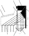
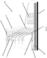
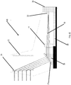
FIGs. 2A-2H in which like reference numeral between depictions are intended to have like meanings. Separate sights are shown generally at 100, 110, 120, 130, 140, 150, 160, and 170 inFIGs. 2A-2H , respectively. Alaser diode 32 emits abeam 10 that interacts with at least onelens element 16 and at least one mirror with afirst mirror 12 and asecond mirror 14 illustrated. It is appreciated that the type of lens elements, number or lens elements, orientation of lens elements, number of mirrors, and orientation of mirrors are all variables that are readily modified without departing from the present invention. Acover plate 28 serves to protect the optics from environmental exposure via the viewing window. Theholographic image 26 is visible on a holographic plate positioned proximal to thecover plate 28. Theholographic image 26 or other indicia is visible against a projection against a sighting field down range of the inventive sight as observed throughtransparent sighting window 13. In some inventive embodiments, anadjustable base 34 is present to adjust the relative position of the aforementioned optical elements. Apower source 38 is provided to energize thelaser diode 32 andelectronics 36 associated with the present invention. - The
inventive sight 110 ofFIG. 2B is also depicted include aholographic grating 21 and a reflectingcollimator 23. A particular compact optical path and overall volume ofsight 120 is noted compared to conventional holographic sights. -
FIG. 3 is a schematic diagram 200 for an embodiment of an inventive holographic sighting system which provides additional detail to theelectronics subsystem 36 as shown in the embodiments ofFIGs. 2A-2H . The operational schematic 200 can be subdivided into three major operational blocks. The first operational block represents power management viavoltage regulator 202, and how all the circuits are powered. The second operational block is themicrocontroller 206 and how the microcontroller is used to interface to external components. The third operational component is the control and settings of thelaser diode 32 vialaser controller 208. Each of these sub-circuits is explained in detail below. - Powering embodiments of the inventive holographic sighting system is achieved through the use of a power source such as a battery or ultracapacitor. Power sources operative herein illustratively include battery formats of AAA, AA and button-type batteries; of various chemistries illustratively including alkaline, lithium, and various rechargeable batteries, each alone or with multiple batteries stacked in series. The
battery power source 38 configuration provides a voltage which is then in turn used to power a switchingvoltage regulator 202. Thevoltage regulator 202 regulates the voltage to a required level for powering themicrocontroller 206 as well as biasing thelaser diode 32. The efficiency of the switchingvoltage regulator 202 is contributes to minimizing the current consumption of the system design of the inventive holographic sighting system. It is noted that emphasis is placed on using a low series resistance capacitor on the output of theregulator 202 which powers the rest of theelectronics board 36. - In certain embodiments of the inventive holographic sighting system, the voltage created from the switching
voltage regulator 202, is supplied to an extremely low-power 8-bit microcontroller 206 that is used for a variety of tasks. Once the inventive holographic sighting system is powered, themicrocontroller 206 puts itself into a low-power state where only an external interrupt from the ON/Increase button found on thepushbutton controller 204 is capable of waking themicrocontroller 206 up. The next state upon waking up themicrocontroller 206 is to check the battery voltage powering thevoltage regulator 202, and comparing the battery voltage to an internally generated voltage by the use of a comparator. If the battery voltage reads below an operating threshold, themicrocontroller 206 flashes thelaser diode 32 indicating a low-battery and then themicrocontroller 206 proceeds to put itself back into a deep sleep. - Upon a successful wake-up, the
microcontroller 206 is then used to generate a pulse-width modulated (PWM) signal used to set the current level of thelaser diode 32, as well as a modulation signal used to pulse thelaser light 10 at a higher frequency thus saving power from the high current consumption of thelaser diode 32. The high frequency modulation signals takes advantage of the fact that thelaser diode 32 is slower in nature to reacting to fast changes which is commonly seen in fiber optic digital communications. The modulation frequency is set by an internal timer or an output of a system clock both generated by themicrocontroller 206. - While in an operating state, the
microcontroller 206 also handles interrupts created by the push-buttons on thepushbutton controller 204 which serves as an interface to a user of the inventive holographic sighting system. With thepushbutton controller 206, the user can turn on the holographic sighting system, increase optical intensity, decrease optical intensity, and turn off the system. - The third operational component or subsystem of the
electronics 36 is the control and settings of thelaser diode 32 vialaser controller 208. In a specific embodiment, control of thelaser diode 32 is accomplished through a pure analog design PWM and PFM techniques. From themicrocontroller 206, the PWM signal is first put through a first order RC-filter (resistor capacitor filter). Doing this allows an average voltage to be fed into an op-amp configured as an integrator which is used to smooth out any abrupt variations that may occur from the modulation portion of thelaser diode control 208. Optical feedback is provided back into the inverting leg of the op-amp, which allows thelaser diode 32 to monitor itself and prevent the current consumption to get out of control and damage thelaser diode 32. The feedback also helps to compensate for the small variations that may occur betweenlaser diodes 32, as well as temperature changes when operating the inventive holographic sight. The optical feedback is obtained from a photodiode's current generation that is scaled appropriately by a resistor connecting the photodiode to ground. In essence, any current through the resistor creates a voltage according to Ohm's law and this is the voltage fed back into the op-amp. Careful selection of an op-amp with small input offset is also emphasized to minimize any inherited offset being that the voltage generated by the photodiode is extremely small and sensitive. The op-amp's output is then fed into a bipolar junction transistor (BJT) which allows small voltages to translate into a small current being passed from the collector to emitter, and achieves a very low current consumption of the holographic sight since the dominating factor for this calculation comes from the intrinsic nature of thelaser diode 32. - Finally, the
laser controller 208 is able to achieve higher optical powers, and yet not be penalized by the current consumption of thelaser diode 32 through the use of a modulation circuit that controls a MOSFET transistor that modulates a path to ground of thelaser diode 32. Being that the response time of thelaser diode 32 is far slower than the frequencies used to modulate thelaser diode 32, a large resistor to ground is used to hold thelaser 10 just below optical lasing. This gives the laser diode 32 a 'running start' whereas driving thelaser diode 32 from a completely grounded signal taxes the system because of the current consumption needed for such a fast response. By using a 'logic-level' MOSFET, the MOSFET can be directly interfaced to themicrocontroller 206 where only a voltage threshold is needed to trigger the MOSFET from an off to an on state. -
FIGs. 4A-4C are a series of perspective views of thelaser diode carrier 70 andadjustment controllers 76 or screws that allow for manual focus of thelaser diode 32 according to embodiments of the invention. As most clearly shown inFIGs. 4A and4C , thelaser diode 32 is mounted to alaser diode carrier 70 with thelaser diode carrier 70 attached to aflexible circuit 78 that allows thelaser diode 32 to be adjusted via thealignment controllers 76. Thealignment controllers 76 attach thelaser diode carrier 70 to thelower body component 80 of embodiments of the inventive holographic sighting system. Thelaser diode carrier 70 is spring loaded by tensioningsprings 74 to eliminate hysteresis during focusing, which is performed on a focusing fixture (not shown). The tensioning springs 74 provide an outward bias to thelaser diode carrier 70 that opposes the tightening action of thealignment controllers 76. As shown inFIG. 4C , which is a top down cross-sectioned view of thelaser diode carrier 70 ofFIG. 4A , that shows the relationship between thealignment controllers 76 and thelaser diode carrier 70. As shown inFIG. 4B , thelaser diode 32 focus may be adjusted externally from thelower body component 80 with an alignment tool such as a hex head screwdriver, or other type of screwdriver or tool that can be inserted or engage into the alignment controllers. In operation, a user adjusts thelaser diode carrier 70 focus orientation via thealignment controllers 76, and when a desired or correct focus is achieved the lockingscrew 72 is tightened, thereby fixing thelaser diode carrier 70 and therefore thelaser diode 32 in the focused position. - The optical cavity seal is a closed cavity channel that provides a non-stressed seal that is applied to the assembled housing components after all settings and adjustments are completed. It is a consistent and reliable seal that is not subject to the vagaries of an assembly process.
FIG. 4D . - The foregoing description is illustrative of particular embodiments of the invention, but is not meant to be a limitation upon the practice thereof. The following claims, including all equivalents thereof, define the scope of the invention.
Claims (6)
- A holographic sighting system for a weapon comprising:an upper housing assembly;a lower housing assembly enclosing two dielectric folding mirrors (12, 14), an on-axis collimating lens (11), and a high efficiency achromatizing holographic optical element (18);an image hologram (26);an anti-reflective glass viewing window (24);a power source (38);a laser diode light source (32) driven by a microcontroller circuit; anda prism (39);wherein the image hologram (26) is a reticule pattern; wherein the high efficiency achromatizing holographic optical element is a holographic transmission grating (18);wherein the holographic sighting system is configured such that the laser diode light source (32) emits a laser beam (10) that is turned by the first dielectric folding mirror (12) and again by the second dielectric folding mirror (14), the beam then being collimated by the collimating lens (11), the collimated beam (15) being incident on the prism (39) and then on the holographic transmission grating (18), the diffracted beam then being incident on the image hologram (26) and being diffracted by the same amount;wherein said upper housing is movable relative to said lower housing; andwherein said image hologram, said window, said power source and said laser diode light source each positioned in either of said upper housing or said lower housing.
- The system of claim 1 further comprising a laser diode carrier for mounting said laser diode light source.
- The system of claim 2 wherein said laser diode carrier is attached to a flexible circuit that allows said laser diode light source to be adjusted via a set of alignment controllers connected between said lower housing assembly and to said laser diode carrier.
- The system of claim 3 wherein said set of alignment controllers further comprise tensioning springs that provide an outward bias to said laser diode carrier that opposes the tightening action of said set of alignment controllers and eliminate hysteresis during focusing.
- The system of claim 3 further comprising a locking screw to fix the laser diode carrier in a focused position once adjusted with said set of alignment controllers.
- The system of claim 5 wherein said set of alignment controllers and said locking screw are adjusted with an alignment tool such as a hex head screwdriver, or other type of screwdriver or tool that can be inserted or engage said set of alignment controllers and said locking screw.
Priority Applications (1)
| Application Number | Priority Date | Filing Date | Title |
|---|---|---|---|
| PL18192418T PL3428569T3 (en) | 2013-07-09 | 2014-07-07 | Modular holographic sighting system |
Applications Claiming Priority (3)
| Application Number | Priority Date | Filing Date | Title |
|---|---|---|---|
| US201361844254P | 2013-07-09 | 2013-07-09 | |
| PCT/US2014/045589 WO2015006222A1 (en) | 2013-07-09 | 2014-07-07 | Modular holographic sighting system |
| EP14822798.6A EP3019812B1 (en) | 2013-07-09 | 2014-07-07 | Modular holographic sighting system |
Related Parent Applications (1)
| Application Number | Title | Priority Date | Filing Date |
|---|---|---|---|
| EP14822798.6A Division EP3019812B1 (en) | 2013-07-09 | 2014-07-07 | Modular holographic sighting system |
Publications (2)
| Publication Number | Publication Date |
|---|---|
| EP3428569A1 EP3428569A1 (en) | 2019-01-16 |
| EP3428569B1 true EP3428569B1 (en) | 2019-12-11 |
Family
ID=52280491
Family Applications (2)
| Application Number | Title | Priority Date | Filing Date |
|---|---|---|---|
| EP14822798.6A Active EP3019812B1 (en) | 2013-07-09 | 2014-07-07 | Modular holographic sighting system |
| EP18192418.4A Active EP3428569B1 (en) | 2013-07-09 | 2014-07-07 | Modular holographic sighting system |
Family Applications Before (1)
| Application Number | Title | Priority Date | Filing Date |
|---|---|---|---|
| EP14822798.6A Active EP3019812B1 (en) | 2013-07-09 | 2014-07-07 | Modular holographic sighting system |
Country Status (6)
| Country | Link |
|---|---|
| US (1) | US9910259B2 (en) |
| EP (2) | EP3019812B1 (en) |
| AU (1) | AU2014287499B2 (en) |
| PL (2) | PL3428569T3 (en) |
| SA (1) | SA516370370B1 (en) |
| WO (1) | WO2015006222A1 (en) |
Families Citing this family (22)
| Publication number | Priority date | Publication date | Assignee | Title |
|---|---|---|---|---|
| KR102323147B1 (en) * | 2015-04-15 | 2021-11-05 | 정보선 | A dot sighting device |
| US10254532B2 (en) * | 2015-06-26 | 2019-04-09 | Ziel Optics, Inc. | Hybrid holographic sight |
| US10113837B2 (en) | 2015-11-03 | 2018-10-30 | N2 Imaging Systems, LLC | Non-contact optical connections for firearm accessories |
| BE1024404B1 (en) * | 2016-07-15 | 2018-02-14 | Fn Herstal S.A. | SIGHT |
| US10753709B2 (en) | 2018-05-17 | 2020-08-25 | Sensors Unlimited, Inc. | Tactical rails, tactical rail systems, and firearm assemblies having tactical rails |
| US10345077B1 (en) * | 2018-06-19 | 2019-07-09 | Hel Technologies, Llc | Holographic optical element with edge lighting |
| US10645348B2 (en) | 2018-07-07 | 2020-05-05 | Sensors Unlimited, Inc. | Data communication between image sensors and image displays |
| US11079202B2 (en) | 2018-07-07 | 2021-08-03 | Sensors Unlimited, Inc. | Boresighting peripherals to digital weapon sights |
| US10742913B2 (en) | 2018-08-08 | 2020-08-11 | N2 Imaging Systems, LLC | Shutterless calibration |
| US10921578B2 (en) | 2018-09-07 | 2021-02-16 | Sensors Unlimited, Inc. | Eyecups for optics |
| US11122698B2 (en) | 2018-11-06 | 2021-09-14 | N2 Imaging Systems, LLC | Low stress electronic board retainers and assemblies |
| US10801813B2 (en) | 2018-11-07 | 2020-10-13 | N2 Imaging Systems, LLC | Adjustable-power data rail on a digital weapon sight |
| US10796860B2 (en) | 2018-12-12 | 2020-10-06 | N2 Imaging Systems, LLC | Hermetically sealed over-molded button assembly |
| US11143838B2 (en) | 2019-01-08 | 2021-10-12 | N2 Imaging Systems, LLC | Optical element retainers |
| US11467391B2 (en) * | 2019-11-21 | 2022-10-11 | Eotech, Llc | Unitary carrier for holographic components |
| US11391904B2 (en) | 2019-11-21 | 2022-07-19 | Eotech, Llc | Temperature stabilized holographic sight |
| US11098980B2 (en) * | 2019-11-21 | 2021-08-24 | Eotech, Llc | Modular weapon sight assembly |
| US11449003B2 (en) | 2019-11-21 | 2022-09-20 | Eotech, Llc | Position adjustment in holographic sight |
| RU196246U1 (en) * | 2019-12-04 | 2020-02-21 | Акционерное общество "Научно-производственное объединение "Государственный институт прикладной оптики" (АО "НПО ГИПО") | HOLOGRAPHIC COLLIMATOR SIGHT |
| RU2740205C1 (en) * | 2020-06-09 | 2021-01-12 | Акционерное общество "Новосибирский приборостроительный завод" | Holographic collimator sight for small arms |
| TR202105554A2 (en) * | 2021-03-27 | 2021-08-23 | Aselsan Hassas Optik Sanayi Ve Ticaret Anonim Sirketi | HOLOGRAPHIC SIGNAL WITH REFLECTIVE CONCAVE DIFFERENCE GRILL |
| CN113568295A (en) * | 2021-07-27 | 2021-10-29 | 三序光学科技(苏州)有限公司 | Volume hologram, preparation method and application in aiming device |
Family Cites Families (71)
| Publication number | Priority date | Publication date | Assignee | Title |
|---|---|---|---|---|
| US4012150A (en) | 1975-08-18 | 1977-03-15 | Environmental Research Institute Of Michigan | Holographic light line sight |
| US5020892A (en) | 1989-09-25 | 1991-06-04 | Burris Company, Inc. | Aperture control for telescopic gunsight |
| US5784182A (en) | 1993-06-17 | 1998-07-21 | Louis-Gilles Francoeur Et Al. | Directional sight for instruments |
| US5473447A (en) * | 1994-02-14 | 1995-12-05 | Polaroid Corporation | Heads-up and heads-down displays employing holographic stereograms |
| US5815936A (en) * | 1994-05-17 | 1998-10-06 | Environmental Research Institute Of Michigan | Detachable hologram assembly and windage/elevation adjuster for a compact holographic sight |
| US5483362A (en) | 1994-05-17 | 1996-01-09 | Environmental Research Institute Of Michigan | Compact holographic sight |
| US5706600A (en) | 1994-07-08 | 1998-01-13 | Crimson Trace Corporation | Laser sighting device for a weapon |
| EP0834206A1 (en) | 1995-06-23 | 1998-04-08 | Coherent, Inc. | Temperature correction circuit for wavelength stabilization in a laser diode |
| US6101200A (en) | 1997-12-24 | 2000-08-08 | Nortel Networks Corporation | Laser module allowing simultaneous wavelength and power control |
| SE513595C2 (en) | 1999-02-22 | 2000-10-09 | Gs Dev Ab | Optical sight with one LED illuminated benchmark |
| US6490060B1 (en) | 1999-10-14 | 2002-12-03 | Eotech, Inc. | Lightweight holographic sight |
| EP1154284A1 (en) | 2000-05-12 | 2001-11-14 | Oerlikon Contraves Ag | Multifunctional optical aiming means |
| US6947458B2 (en) | 2001-06-07 | 2005-09-20 | Alcatel Communications, Inc. | Power control circuit for laser diode having wavelength compensation |
| US6751014B2 (en) | 2001-06-19 | 2004-06-15 | International Business Machines Corporation | Automatic gain control and dynamic equalization of erbium doped optical amplifiers in wavelength multiplexing networks |
| US6738187B2 (en) | 2001-06-27 | 2004-05-18 | International Business Machines Corporation | Semiconductor optical amplifiers using wavelength locked loop tuning and equalization |
| US6654152B2 (en) | 2001-09-25 | 2003-11-25 | International Business Machines Corporation | Frequency guiding filter for dispersion managed soliton transmission |
| US7190904B2 (en) | 2001-09-26 | 2007-03-13 | International Business Machines Corporation | Wavelength modulation for optical based switching and routing |
| WO2003032547A2 (en) | 2001-10-09 | 2003-04-17 | Infinera Corporation | Transmitter photonic integrated circuit |
| SE524172C2 (en) | 2002-06-24 | 2004-07-06 | Gs Dev Ab | weapon sight |
| US7356057B2 (en) | 2002-10-31 | 2008-04-08 | Finisar Corporation | Wide temperature range vertical cavity surface emitting laser |
| US7069685B2 (en) * | 2003-09-12 | 2006-07-04 | Lasermax, Inc. | Diffractive head up display for firearms |
| US20050073690A1 (en) | 2003-10-03 | 2005-04-07 | Abbink Russell E. | Optical spectroscopy incorporating a vertical cavity surface emitting laser (VCSEL) |
| JP3984214B2 (en) | 2003-10-21 | 2007-10-03 | ローム株式会社 | Light emission control device |
| US7096619B2 (en) | 2004-02-17 | 2006-08-29 | Jackson Charles L | Equipment operator personalization device |
| US20060022213A1 (en) | 2004-08-02 | 2006-02-02 | Posamentier Joshua D | TO-can heater on flex circuit |
| US7145703B2 (en) * | 2005-01-27 | 2006-12-05 | Eotech Acquisition Corp. | Low profile holographic sight and method of manufacturing same |
| CN101351935A (en) | 2005-07-18 | 2009-01-21 | Mrv通信公司 | Laser wavelength stabilization |
| JP4641478B2 (en) | 2005-09-27 | 2011-03-02 | キヤノン株式会社 | Optical scanning device and image forming apparatus using the same |
| US7752798B2 (en) * | 2005-10-14 | 2010-07-13 | Mayerle Ronald T | See-through periscope for sighting-in optical or open sights on a firearm |
| BE1016981A3 (en) | 2006-02-08 | 2007-11-06 | Fn Herstal Sa | IMPROVED VISOR WITH RED MOBILE BRIDGE. |
| US8089995B2 (en) | 2006-07-12 | 2012-01-03 | Oracle America, Inc. | Structures and methods for adjusting the wavelengths of lasers via temperature control |
| US8233209B2 (en) | 2007-01-31 | 2012-07-31 | Ricoh Company, Limited | Optical scanning device and image forming apparatus |
| US8235605B2 (en) | 2007-03-19 | 2012-08-07 | Jeong Soo Kim | Self-standing parallel plate beam splitter, method for manufacturing the same, and laser diode package structure using the same |
| EP2201342A2 (en) | 2007-10-03 | 2010-06-30 | Dublin Institute of Technology | A multipoint laser doppler vibrometer |
| EP2245904A2 (en) | 2008-01-28 | 2010-11-03 | Nxp B.V. | System and method for estimating the junction temperature of a light emitting diode |
| US8756852B2 (en) | 2008-04-30 | 2014-06-24 | Safariland, Llc | Non-lethal/lethal projectile launcher ranging and sighting system |
| JP5616343B2 (en) | 2008-09-17 | 2014-10-29 | コーニンクレッカ フィリップス エヌ ヴェ | Wavelength control semiconductor laser device |
| US8879146B2 (en) | 2008-09-30 | 2014-11-04 | Truglo, Inc. | Reflective dot sighting device with perceived dot location |
| US8607495B2 (en) | 2008-10-10 | 2013-12-17 | Larry E. Moore | Light-assisted sighting devices |
| US8208507B2 (en) | 2008-12-18 | 2012-06-26 | Finisar Corporation | Feedback control for heated TOSA |
| US8888491B2 (en) | 2009-02-27 | 2014-11-18 | OPTO Ballistics | Optical recognition system and method for simulated shooting |
| US8559821B2 (en) | 2009-12-02 | 2013-10-15 | Futurewei Technologies, Inc. | Wavelength stabilization and locking for colorless dense wavelength division multiplexing transmitters |
| US8567981B2 (en) * | 2010-02-04 | 2013-10-29 | Elite Research, Llc | Laser aiming device integrated into an electro-optic battery source such as associated with a holographic sight |
| US20110228803A1 (en) | 2010-03-19 | 2011-09-22 | Finisar Corporation | Vcsel with integral resistive region |
| US20110228366A1 (en) * | 2010-03-22 | 2011-09-22 | Shou LIU | Hoe optical system for holographic sight |
| US8605763B2 (en) | 2010-03-31 | 2013-12-10 | Microsoft Corporation | Temperature measurement and control for laser and light-emitting diodes |
| US20120033195A1 (en) | 2010-08-05 | 2012-02-09 | L-3 Communications Eotech, Inc. | Multipurpose Aiming Sight with Head-Up Display Module |
| US9121672B2 (en) | 2011-01-01 | 2015-09-01 | G. David Tubb | Ballistic effect compensating reticle and aim compensation method with sloped mil and MOA wind dot lines |
| CN102175096B (en) | 2011-02-14 | 2013-11-13 | 厦门大学 | Holographic gun aiming optical system |
| SE1150113A1 (en) | 2011-02-14 | 2012-08-15 | Gs Dev Ab | Fire control systems |
| US8833655B2 (en) | 2011-05-26 | 2014-09-16 | Burris Corporation | Magnification compensating sighting systems and methods |
| US20140109457A1 (en) | 2011-06-21 | 2014-04-24 | Walter Speroni | Weapon sighting system |
| US8837877B2 (en) | 2011-08-11 | 2014-09-16 | Massachusetts Institute Of Technology | Patterned non-reciprocal optical resonator |
| US8713844B2 (en) | 2011-09-26 | 2014-05-06 | Lasermax Inc | Firearm laser sight alignment assembly |
| CN103763974B (en) | 2011-09-30 | 2016-07-06 | 松下知识产权经营株式会社 | Automatic head nursing device and automatically head nursing method |
| ITFI20110266A1 (en) | 2011-12-09 | 2013-06-10 | Selex Galileo Spa | "MIRA SYSTEM" |
| US8638387B2 (en) | 2012-01-25 | 2014-01-28 | Optex Systems, Inc. | Multiple spectral single image sighting system using single objective lens set |
| US8739454B2 (en) | 2012-04-05 | 2014-06-03 | Dead Ringer, LLC | Gun sight with range finder |
| US20140295380A1 (en) | 2012-04-27 | 2014-10-02 | Dynamic Animation Systems, Inc. | System and method for zeroing a weapon |
| US8434397B1 (en) | 2012-06-08 | 2013-05-07 | The United States Of America As Represented By The Secretary Of The Navy | Helicopter weapon mounting system |
| US9222752B2 (en) | 2012-07-05 | 2015-12-29 | Klint M. Kingsbury | Light gathering adjustable ballistic reticule |
| WO2014056105A2 (en) | 2012-10-09 | 2014-04-17 | Mcmaster University | Integrated thermal stabilization of a microring resonator |
| US9631896B2 (en) | 2012-11-15 | 2017-04-25 | C. Michael Scroggins | Projectile aiming optical system |
| WO2014081781A1 (en) | 2012-11-20 | 2014-05-30 | Kruger Optical, Inc. | Rifle scope having elevation and windage ocular display |
| US8844189B2 (en) | 2012-12-06 | 2014-09-30 | P&L Industries, Inc. | Sighting device replicating shotgun pattern spread |
| US8948220B2 (en) | 2012-12-18 | 2015-02-03 | Coherent Gmbh | Wavelength-stabilized microcrystal laser |
| US8887430B2 (en) | 2013-01-10 | 2014-11-18 | Brian Donald Wichner | Shooter aim detection and warning system |
| US9291808B2 (en) | 2013-03-15 | 2016-03-22 | Leupold & Stevens, Inc. | Combination optical aiming device for projectile weapons |
| US9803961B2 (en) | 2013-03-15 | 2017-10-31 | Keith A. Averill | Sighting apparatus and method |
| US9057584B2 (en) | 2013-04-12 | 2015-06-16 | International Trade and Technologies, Inc. | Modular universal machinegun sight with bullet drop compensation device |
| US20140334058A1 (en) | 2013-05-13 | 2014-11-13 | David W. Galvan | Automated and remotely operated stun gun with integrated camera and laser sight |
-
2014
- 2014-07-07 EP EP14822798.6A patent/EP3019812B1/en active Active
- 2014-07-07 US US14/903,537 patent/US9910259B2/en active Active
- 2014-07-07 EP EP18192418.4A patent/EP3428569B1/en active Active
- 2014-07-07 AU AU2014287499A patent/AU2014287499B2/en not_active Ceased
- 2014-07-07 WO PCT/US2014/045589 patent/WO2015006222A1/en active Application Filing
- 2014-07-07 PL PL18192418T patent/PL3428569T3/en unknown
- 2014-07-07 PL PL14822798T patent/PL3019812T3/en unknown
-
2016
- 2016-01-07 SA SA516370370A patent/SA516370370B1/en unknown
Non-Patent Citations (1)
| Title |
|---|
| None * |
Also Published As
| Publication number | Publication date |
|---|---|
| US9910259B2 (en) | 2018-03-06 |
| AU2014287499A1 (en) | 2016-03-03 |
| PL3428569T3 (en) | 2020-11-16 |
| EP3019812A1 (en) | 2016-05-18 |
| AU2014287499B2 (en) | 2017-12-21 |
| EP3019812B1 (en) | 2018-09-05 |
| WO2015006222A1 (en) | 2015-01-15 |
| EP3428569A1 (en) | 2019-01-16 |
| EP3019812A4 (en) | 2017-04-05 |
| US20160161735A1 (en) | 2016-06-09 |
| SA516370370B1 (en) | 2020-06-02 |
| PL3019812T3 (en) | 2019-04-30 |
Similar Documents
| Publication | Publication Date | Title |
|---|---|---|
| EP3428569B1 (en) | Modular holographic sighting system | |
| US10184756B1 (en) | Rail mounted weapon light | |
| US5359779A (en) | Illumination and laser sighting device for a weapon | |
| US11018476B2 (en) | Laser module and system | |
| US7145703B2 (en) | Low profile holographic sight and method of manufacturing same | |
| US7784192B2 (en) | SWIR vision and illumination devices | |
| EP2577213B1 (en) | Gun sight | |
| US7726061B1 (en) | Dual beam laser module | |
| US5483362A (en) | Compact holographic sight | |
| EP2751513B1 (en) | Reflex sight | |
| US5052801A (en) | Compact laser-assisted weapon sight | |
| JP2016502642A (en) | System, method and apparatus for providing a firearm sight | |
| US4940324A (en) | Electronic sight having a larger horizontal viewing field than a vertical viewing field and method of making same | |
| JP2001500990A (en) | Optical aiming device | |
| US10190847B2 (en) | Recoil spring guide mounted target marker | |
| KR20070048621A (en) | Modular night vision assemblies | |
| CN103994337A (en) | LED strong-light flashlight with laser pointer | |
| KR100669859B1 (en) | The dot sisht device | |
| CN204268971U (en) | A kind of interior red some rifle with auxiliary aiming function is taken aim at | |
| WO2019233156A1 (en) | Multi-functional sight | |
| RU207601U1 (en) | Laser designator | |
| CN2578774Y (en) | Zero calibrator for gun optical sights | |
| CN218514550U (en) | Geodetic surveying collimation system and device | |
| CN215953962U (en) | Binocular telescope | |
| US20240159500A1 (en) | Aiming device for firearm |
Legal Events
| Date | Code | Title | Description |
|---|---|---|---|
| PUAI | Public reference made under article 153(3) epc to a published international application that has entered the european phase |
Free format text: ORIGINAL CODE: 0009012 |
|
| STAA | Information on the status of an ep patent application or granted ep patent |
Free format text: STATUS: THE APPLICATION HAS BEEN PUBLISHED |
|
| AC | Divisional application: reference to earlier application |
Ref document number: 3019812 Country of ref document: EP Kind code of ref document: P |
|
| AK | Designated contracting states |
Kind code of ref document: A1 Designated state(s): AL AT BE BG CH CY CZ DE DK EE ES FI FR GB GR HR HU IE IS IT LI LT LU LV MC MK MT NL NO PL PT RO RS SE SI SK SM TR |
|
| STAA | Information on the status of an ep patent application or granted ep patent |
Free format text: STATUS: REQUEST FOR EXAMINATION WAS MADE |
|
| 17P | Request for examination filed |
Effective date: 20190227 |
|
| RBV | Designated contracting states (corrected) |
Designated state(s): AL AT BE BG CH CY CZ DE DK EE ES FI FR GB GR HR HU IE IS IT LI LT LU LV MC MK MT NL NO PL PT RO RS SE SI SK SM TR |
|
| REG | Reference to a national code |
Ref country code: DE Ref legal event code: R079 Ref document number: 602014058450 Country of ref document: DE Free format text: PREVIOUS MAIN CLASS: F41G0001020000 Ipc: G02B0005080000 |
|
| GRAP | Despatch of communication of intention to grant a patent |
Free format text: ORIGINAL CODE: EPIDOSNIGR1 |
|
| STAA | Information on the status of an ep patent application or granted ep patent |
Free format text: STATUS: GRANT OF PATENT IS INTENDED |
|
| INTG | Intention to grant announced |
Effective date: 20190726 |
|
| RIC1 | Information provided on ipc code assigned before grant |
Ipc: G02B 5/08 20060101AFI20190715BHEP Ipc: F41G 1/14 20060101ALI20190715BHEP Ipc: G02B 27/42 20060101ALI20190715BHEP Ipc: G02B 19/00 20060101ALI20190715BHEP Ipc: G02B 5/32 20060101ALI20190715BHEP Ipc: G02B 27/00 20060101ALI20190715BHEP Ipc: G02B 27/20 20060101ALI20190715BHEP Ipc: G02B 17/02 20060101ALI20190715BHEP Ipc: F41G 1/34 20060101ALI20190715BHEP Ipc: G02B 23/14 20060101ALI20190715BHEP |
|
| GRAS | Grant fee paid |
Free format text: ORIGINAL CODE: EPIDOSNIGR3 |
|
| GRAA | (expected) grant |
Free format text: ORIGINAL CODE: 0009210 |
|
| STAA | Information on the status of an ep patent application or granted ep patent |
Free format text: STATUS: THE PATENT HAS BEEN GRANTED |
|
| AC | Divisional application: reference to earlier application |
Ref document number: 3019812 Country of ref document: EP Kind code of ref document: P |
|
| AK | Designated contracting states |
Kind code of ref document: B1 Designated state(s): AL AT BE BG CH CY CZ DE DK EE ES FI FR GB GR HR HU IE IS IT LI LT LU LV MC MK MT NL NO PL PT RO RS SE SI SK SM TR |
|
| REG | Reference to a national code |
Ref country code: GB Ref legal event code: FG4D |
|
| REG | Reference to a national code |
Ref country code: CH Ref legal event code: EP |
|
| REG | Reference to a national code |
Ref country code: AT Ref legal event code: REF Ref document number: 1212763 Country of ref document: AT Kind code of ref document: T Effective date: 20191215 |
|
| REG | Reference to a national code |
Ref country code: DE Ref legal event code: R096 Ref document number: 602014058450 Country of ref document: DE |
|
| REG | Reference to a national code |
Ref country code: IE Ref legal event code: FG4D |
|
| REG | Reference to a national code |
Ref country code: NL Ref legal event code: MP Effective date: 20191211 |
|
| REG | Reference to a national code |
Ref country code: LT Ref legal event code: MG4D |
|
| PG25 | Lapsed in a contracting state [announced via postgrant information from national office to epo] |
Ref country code: SE Free format text: LAPSE BECAUSE OF FAILURE TO SUBMIT A TRANSLATION OF THE DESCRIPTION OR TO PAY THE FEE WITHIN THE PRESCRIBED TIME-LIMIT Effective date: 20191211 Ref country code: LV Free format text: LAPSE BECAUSE OF FAILURE TO SUBMIT A TRANSLATION OF THE DESCRIPTION OR TO PAY THE FEE WITHIN THE PRESCRIBED TIME-LIMIT Effective date: 20191211 Ref country code: NO Free format text: LAPSE BECAUSE OF FAILURE TO SUBMIT A TRANSLATION OF THE DESCRIPTION OR TO PAY THE FEE WITHIN THE PRESCRIBED TIME-LIMIT Effective date: 20200311 Ref country code: GR Free format text: LAPSE BECAUSE OF FAILURE TO SUBMIT A TRANSLATION OF THE DESCRIPTION OR TO PAY THE FEE WITHIN THE PRESCRIBED TIME-LIMIT Effective date: 20200312 Ref country code: BG Free format text: LAPSE BECAUSE OF FAILURE TO SUBMIT A TRANSLATION OF THE DESCRIPTION OR TO PAY THE FEE WITHIN THE PRESCRIBED TIME-LIMIT Effective date: 20200311 Ref country code: FI Free format text: LAPSE BECAUSE OF FAILURE TO SUBMIT A TRANSLATION OF THE DESCRIPTION OR TO PAY THE FEE WITHIN THE PRESCRIBED TIME-LIMIT Effective date: 20191211 Ref country code: LT Free format text: LAPSE BECAUSE OF FAILURE TO SUBMIT A TRANSLATION OF THE DESCRIPTION OR TO PAY THE FEE WITHIN THE PRESCRIBED TIME-LIMIT Effective date: 20191211 |
|
| PG25 | Lapsed in a contracting state [announced via postgrant information from national office to epo] |
Ref country code: RS Free format text: LAPSE BECAUSE OF FAILURE TO SUBMIT A TRANSLATION OF THE DESCRIPTION OR TO PAY THE FEE WITHIN THE PRESCRIBED TIME-LIMIT Effective date: 20191211 Ref country code: HR Free format text: LAPSE BECAUSE OF FAILURE TO SUBMIT A TRANSLATION OF THE DESCRIPTION OR TO PAY THE FEE WITHIN THE PRESCRIBED TIME-LIMIT Effective date: 20191211 |
|
| PG25 | Lapsed in a contracting state [announced via postgrant information from national office to epo] |
Ref country code: AL Free format text: LAPSE BECAUSE OF FAILURE TO SUBMIT A TRANSLATION OF THE DESCRIPTION OR TO PAY THE FEE WITHIN THE PRESCRIBED TIME-LIMIT Effective date: 20191211 |
|
| PG25 | Lapsed in a contracting state [announced via postgrant information from national office to epo] |
Ref country code: RO Free format text: LAPSE BECAUSE OF FAILURE TO SUBMIT A TRANSLATION OF THE DESCRIPTION OR TO PAY THE FEE WITHIN THE PRESCRIBED TIME-LIMIT Effective date: 20191211 Ref country code: EE Free format text: LAPSE BECAUSE OF FAILURE TO SUBMIT A TRANSLATION OF THE DESCRIPTION OR TO PAY THE FEE WITHIN THE PRESCRIBED TIME-LIMIT Effective date: 20191211 Ref country code: PT Free format text: LAPSE BECAUSE OF FAILURE TO SUBMIT A TRANSLATION OF THE DESCRIPTION OR TO PAY THE FEE WITHIN THE PRESCRIBED TIME-LIMIT Effective date: 20200506 Ref country code: ES Free format text: LAPSE BECAUSE OF FAILURE TO SUBMIT A TRANSLATION OF THE DESCRIPTION OR TO PAY THE FEE WITHIN THE PRESCRIBED TIME-LIMIT Effective date: 20191211 Ref country code: NL Free format text: LAPSE BECAUSE OF FAILURE TO SUBMIT A TRANSLATION OF THE DESCRIPTION OR TO PAY THE FEE WITHIN THE PRESCRIBED TIME-LIMIT Effective date: 20191211 Ref country code: CZ Free format text: LAPSE BECAUSE OF FAILURE TO SUBMIT A TRANSLATION OF THE DESCRIPTION OR TO PAY THE FEE WITHIN THE PRESCRIBED TIME-LIMIT Effective date: 20191211 |
|
| PG25 | Lapsed in a contracting state [announced via postgrant information from national office to epo] |
Ref country code: SM Free format text: LAPSE BECAUSE OF FAILURE TO SUBMIT A TRANSLATION OF THE DESCRIPTION OR TO PAY THE FEE WITHIN THE PRESCRIBED TIME-LIMIT Effective date: 20191211 Ref country code: SK Free format text: LAPSE BECAUSE OF FAILURE TO SUBMIT A TRANSLATION OF THE DESCRIPTION OR TO PAY THE FEE WITHIN THE PRESCRIBED TIME-LIMIT Effective date: 20191211 Ref country code: IS Free format text: LAPSE BECAUSE OF FAILURE TO SUBMIT A TRANSLATION OF THE DESCRIPTION OR TO PAY THE FEE WITHIN THE PRESCRIBED TIME-LIMIT Effective date: 20200411 |
|
| REG | Reference to a national code |
Ref country code: DE Ref legal event code: R097 Ref document number: 602014058450 Country of ref document: DE |
|
| REG | Reference to a national code |
Ref country code: AT Ref legal event code: MK05 Ref document number: 1212763 Country of ref document: AT Kind code of ref document: T Effective date: 20191211 |
|
| PLBE | No opposition filed within time limit |
Free format text: ORIGINAL CODE: 0009261 |
|
| STAA | Information on the status of an ep patent application or granted ep patent |
Free format text: STATUS: NO OPPOSITION FILED WITHIN TIME LIMIT |
|
| PG25 | Lapsed in a contracting state [announced via postgrant information from national office to epo] |
Ref country code: DK Free format text: LAPSE BECAUSE OF FAILURE TO SUBMIT A TRANSLATION OF THE DESCRIPTION OR TO PAY THE FEE WITHIN THE PRESCRIBED TIME-LIMIT Effective date: 20191211 |
|
| 26N | No opposition filed |
Effective date: 20200914 |
|
| PG25 | Lapsed in a contracting state [announced via postgrant information from national office to epo] |
Ref country code: SI Free format text: LAPSE BECAUSE OF FAILURE TO SUBMIT A TRANSLATION OF THE DESCRIPTION OR TO PAY THE FEE WITHIN THE PRESCRIBED TIME-LIMIT Effective date: 20191211 Ref country code: AT Free format text: LAPSE BECAUSE OF FAILURE TO SUBMIT A TRANSLATION OF THE DESCRIPTION OR TO PAY THE FEE WITHIN THE PRESCRIBED TIME-LIMIT Effective date: 20191211 |
|
| PG25 | Lapsed in a contracting state [announced via postgrant information from national office to epo] |
Ref country code: IT Free format text: LAPSE BECAUSE OF FAILURE TO SUBMIT A TRANSLATION OF THE DESCRIPTION OR TO PAY THE FEE WITHIN THE PRESCRIBED TIME-LIMIT Effective date: 20191211 |
|
| PG25 | Lapsed in a contracting state [announced via postgrant information from national office to epo] |
Ref country code: MC Free format text: LAPSE BECAUSE OF FAILURE TO SUBMIT A TRANSLATION OF THE DESCRIPTION OR TO PAY THE FEE WITHIN THE PRESCRIBED TIME-LIMIT Effective date: 20191211 |
|
| REG | Reference to a national code |
Ref country code: CH Ref legal event code: PL |
|
| REG | Reference to a national code |
Ref country code: BE Ref legal event code: MM Effective date: 20200731 |
|
| PG25 | Lapsed in a contracting state [announced via postgrant information from national office to epo] |
Ref country code: CH Free format text: LAPSE BECAUSE OF NON-PAYMENT OF DUE FEES Effective date: 20200731 Ref country code: LI Free format text: LAPSE BECAUSE OF NON-PAYMENT OF DUE FEES Effective date: 20200731 Ref country code: LU Free format text: LAPSE BECAUSE OF NON-PAYMENT OF DUE FEES Effective date: 20200707 Ref country code: IE Free format text: LAPSE BECAUSE OF NON-PAYMENT OF DUE FEES Effective date: 20200707 |
|
| PG25 | Lapsed in a contracting state [announced via postgrant information from national office to epo] |
Ref country code: BE Free format text: LAPSE BECAUSE OF NON-PAYMENT OF DUE FEES Effective date: 20200731 |
|
| PG25 | Lapsed in a contracting state [announced via postgrant information from national office to epo] |
Ref country code: MT Free format text: LAPSE BECAUSE OF FAILURE TO SUBMIT A TRANSLATION OF THE DESCRIPTION OR TO PAY THE FEE WITHIN THE PRESCRIBED TIME-LIMIT Effective date: 20191211 Ref country code: CY Free format text: LAPSE BECAUSE OF FAILURE TO SUBMIT A TRANSLATION OF THE DESCRIPTION OR TO PAY THE FEE WITHIN THE PRESCRIBED TIME-LIMIT Effective date: 20191211 |
|
| PG25 | Lapsed in a contracting state [announced via postgrant information from national office to epo] |
Ref country code: MK Free format text: LAPSE BECAUSE OF FAILURE TO SUBMIT A TRANSLATION OF THE DESCRIPTION OR TO PAY THE FEE WITHIN THE PRESCRIBED TIME-LIMIT Effective date: 20191211 |
|
| PGFP | Annual fee paid to national office [announced via postgrant information from national office to epo] |
Ref country code: TR Payment date: 20220705 Year of fee payment: 9 Ref country code: GB Payment date: 20220822 Year of fee payment: 9 Ref country code: DE Payment date: 20220819 Year of fee payment: 9 |
|
| PGFP | Annual fee paid to national office [announced via postgrant information from national office to epo] |
Ref country code: PL Payment date: 20220705 Year of fee payment: 9 Ref country code: FR Payment date: 20220823 Year of fee payment: 9 |
|
| REG | Reference to a national code |
Ref country code: DE Ref legal event code: R119 Ref document number: 602014058450 Country of ref document: DE |
|
| GBPC | Gb: european patent ceased through non-payment of renewal fee |
Effective date: 20230707 |
|
| PG25 | Lapsed in a contracting state [announced via postgrant information from national office to epo] |
Ref country code: DE Free format text: LAPSE BECAUSE OF NON-PAYMENT OF DUE FEES Effective date: 20240201 Ref country code: GB Free format text: LAPSE BECAUSE OF NON-PAYMENT OF DUE FEES Effective date: 20230707 |