EP3428514B1 - Lighting device for vehicles provided with cooled lighting modules - Google Patents
Lighting device for vehicles provided with cooled lighting modules Download PDFInfo
- Publication number
- EP3428514B1 EP3428514B1 EP17180838.9A EP17180838A EP3428514B1 EP 3428514 B1 EP3428514 B1 EP 3428514B1 EP 17180838 A EP17180838 A EP 17180838A EP 3428514 B1 EP3428514 B1 EP 3428514B1
- Authority
- EP
- European Patent Office
- Prior art keywords
- linear channel
- lighting device
- radiator element
- lens
- open end
- Prior art date
- Legal status (The legal status is an assumption and is not a legal conclusion. Google has not performed a legal analysis and makes no representation as to the accuracy of the status listed.)
- Active
Links
- 230000003287 optical effect Effects 0.000 claims description 9
- 239000000463 material Substances 0.000 claims description 4
- 229910052782 aluminium Inorganic materials 0.000 claims description 2
- XAGFODPZIPBFFR-UHFFFAOYSA-N aluminium Chemical compound [Al] XAGFODPZIPBFFR-UHFFFAOYSA-N 0.000 claims description 2
- 229910001234 light alloy Inorganic materials 0.000 claims description 2
- 229910001092 metal group alloy Inorganic materials 0.000 claims description 2
- 230000005494 condensation Effects 0.000 description 5
- 238000009833 condensation Methods 0.000 description 5
- 238000001816 cooling Methods 0.000 description 2
- 239000000853 adhesive Substances 0.000 description 1
- 230000001070 adhesive effect Effects 0.000 description 1
- 238000010276 construction Methods 0.000 description 1
- 230000008030 elimination Effects 0.000 description 1
- 238000003379 elimination reaction Methods 0.000 description 1
- 238000001746 injection moulding Methods 0.000 description 1
- 239000011347 resin Substances 0.000 description 1
- 229920005989 resin Polymers 0.000 description 1
- 229920001187 thermosetting polymer Polymers 0.000 description 1
Images


Classifications
-
- F—MECHANICAL ENGINEERING; LIGHTING; HEATING; WEAPONS; BLASTING
- F21—LIGHTING
- F21S—NON-PORTABLE LIGHTING DEVICES; SYSTEMS THEREOF; VEHICLE LIGHTING DEVICES SPECIALLY ADAPTED FOR VEHICLE EXTERIORS
- F21S45/00—Arrangements within vehicle lighting devices specially adapted for vehicle exteriors, for purposes other than emission or distribution of light
- F21S45/40—Cooling of lighting devices
- F21S45/42—Forced cooling
- F21S45/43—Forced cooling using gas
-
- F—MECHANICAL ENGINEERING; LIGHTING; HEATING; WEAPONS; BLASTING
- F21—LIGHTING
- F21S—NON-PORTABLE LIGHTING DEVICES; SYSTEMS THEREOF; VEHICLE LIGHTING DEVICES SPECIALLY ADAPTED FOR VEHICLE EXTERIORS
- F21S45/00—Arrangements within vehicle lighting devices specially adapted for vehicle exteriors, for purposes other than emission or distribution of light
- F21S45/40—Cooling of lighting devices
- F21S45/47—Passive cooling, e.g. using fins, thermal conductive elements or openings
- F21S45/48—Passive cooling, e.g. using fins, thermal conductive elements or openings with means for conducting heat from the inside to the outside of the lighting devices, e.g. with fins on the outer surface of the lighting device
-
- F—MECHANICAL ENGINEERING; LIGHTING; HEATING; WEAPONS; BLASTING
- F21—LIGHTING
- F21V—FUNCTIONAL FEATURES OR DETAILS OF LIGHTING DEVICES OR SYSTEMS THEREOF; STRUCTURAL COMBINATIONS OF LIGHTING DEVICES WITH OTHER ARTICLES, NOT OTHERWISE PROVIDED FOR
- F21V29/00—Protecting lighting devices from thermal damage; Cooling or heating arrangements specially adapted for lighting devices or systems
- F21V29/50—Cooling arrangements
- F21V29/60—Cooling arrangements characterised by the use of a forced flow of gas, e.g. air
- F21V29/67—Cooling arrangements characterised by the use of a forced flow of gas, e.g. air characterised by the arrangement of fans
- F21V29/677—Cooling arrangements characterised by the use of a forced flow of gas, e.g. air characterised by the arrangement of fans the fans being used for discharging
-
- F—MECHANICAL ENGINEERING; LIGHTING; HEATING; WEAPONS; BLASTING
- F21—LIGHTING
- F21V—FUNCTIONAL FEATURES OR DETAILS OF LIGHTING DEVICES OR SYSTEMS THEREOF; STRUCTURAL COMBINATIONS OF LIGHTING DEVICES WITH OTHER ARTICLES, NOT OTHERWISE PROVIDED FOR
- F21V29/00—Protecting lighting devices from thermal damage; Cooling or heating arrangements specially adapted for lighting devices or systems
- F21V29/50—Cooling arrangements
- F21V29/70—Cooling arrangements characterised by passive heat-dissipating elements, e.g. heat-sinks
- F21V29/74—Cooling arrangements characterised by passive heat-dissipating elements, e.g. heat-sinks with fins or blades
- F21V29/76—Cooling arrangements characterised by passive heat-dissipating elements, e.g. heat-sinks with fins or blades with essentially identical parallel planar fins or blades, e.g. with comb-like cross-section
- F21V29/767—Cooling arrangements characterised by passive heat-dissipating elements, e.g. heat-sinks with fins or blades with essentially identical parallel planar fins or blades, e.g. with comb-like cross-section the planes containing the fins or blades having directions perpendicular to the light emitting axis
-
- F—MECHANICAL ENGINEERING; LIGHTING; HEATING; WEAPONS; BLASTING
- F21—LIGHTING
- F21V—FUNCTIONAL FEATURES OR DETAILS OF LIGHTING DEVICES OR SYSTEMS THEREOF; STRUCTURAL COMBINATIONS OF LIGHTING DEVICES WITH OTHER ARTICLES, NOT OTHERWISE PROVIDED FOR
- F21V29/00—Protecting lighting devices from thermal damage; Cooling or heating arrangements specially adapted for lighting devices or systems
- F21V29/85—Protecting lighting devices from thermal damage; Cooling or heating arrangements specially adapted for lighting devices or systems characterised by the material
- F21V29/87—Organic material, e.g. filled polymer composites; Thermo-conductive additives or coatings therefor
-
- F—MECHANICAL ENGINEERING; LIGHTING; HEATING; WEAPONS; BLASTING
- F21—LIGHTING
- F21S—NON-PORTABLE LIGHTING DEVICES; SYSTEMS THEREOF; VEHICLE LIGHTING DEVICES SPECIALLY ADAPTED FOR VEHICLE EXTERIORS
- F21S41/00—Illuminating devices specially adapted for vehicle exteriors, e.g. headlamps
- F21S41/10—Illuminating devices specially adapted for vehicle exteriors, e.g. headlamps characterised by the light source
- F21S41/14—Illuminating devices specially adapted for vehicle exteriors, e.g. headlamps characterised by the light source characterised by the type of light source
- F21S41/141—Light emitting diodes [LED]
- F21S41/143—Light emitting diodes [LED] the main emission direction of the LED being parallel to the optical axis of the illuminating device
-
- F—MECHANICAL ENGINEERING; LIGHTING; HEATING; WEAPONS; BLASTING
- F21—LIGHTING
- F21S—NON-PORTABLE LIGHTING DEVICES; SYSTEMS THEREOF; VEHICLE LIGHTING DEVICES SPECIALLY ADAPTED FOR VEHICLE EXTERIORS
- F21S45/00—Arrangements within vehicle lighting devices specially adapted for vehicle exteriors, for purposes other than emission or distribution of light
- F21S45/40—Cooling of lighting devices
- F21S45/47—Passive cooling, e.g. using fins, thermal conductive elements or openings
-
- F—MECHANICAL ENGINEERING; LIGHTING; HEATING; WEAPONS; BLASTING
- F21—LIGHTING
- F21W—INDEXING SCHEME ASSOCIATED WITH SUBCLASSES F21K, F21L, F21S and F21V, RELATING TO USES OR APPLICATIONS OF LIGHTING DEVICES OR SYSTEMS
- F21W2102/00—Exterior vehicle lighting devices for illuminating purposes
- F21W2102/10—Arrangement or contour of the emitted light
- F21W2102/13—Arrangement or contour of the emitted light for high-beam region or low-beam region
-
- F—MECHANICAL ENGINEERING; LIGHTING; HEATING; WEAPONS; BLASTING
- F21—LIGHTING
- F21Y—INDEXING SCHEME ASSOCIATED WITH SUBCLASSES F21K, F21L, F21S and F21V, RELATING TO THE FORM OR THE KIND OF THE LIGHT SOURCES OR OF THE COLOUR OF THE LIGHT EMITTED
- F21Y2115/00—Light-generating elements of semiconductor light sources
- F21Y2115/10—Light-emitting diodes [LED]
Definitions
- the present invention relates to a lighting device equipped with one or more lighting modules, preferably using LEDs as a light source and having a cooling system that allow in use the outer lens or transparent cover of the lighting device, which closes frontally the housing body of the lighting device, to be defrosted and/or the eventual condensation to be eliminated.
- Lighting devices for vehicles provided with one or more lighting modules arranged inside a housing body having a frontal inlet opening closed by a lens or a transparent cover are well known.
- a housing body having a frontal inlet opening closed by a lens or a transparent cover are well known.
- the condensation forms on the inner side of the lens/cover this may cause also damages to the electronic components and/or to the reflective surfaces of the lighting modules.
- EP2148133 discloses a lighting device comprising two superimposed lighting modules arranged within an housing body; in the vertical space between the two lighting modules is arranged a radiator including a plurality of parallel fins laterally spaced apart to each other; a fan arranged at the rear of the lighting device and inside the housing body sucks the air present within the housing body from the top and the bottom of the housing body and delivers it through the radiator fins, which are crossed in the direction of their width, and toward the inner surface of a lens or transparent cover closing an inlet opening arranged at the front of the housing body.
- the lighting device disclosed in EP2148133 is far from being satisfactory: first of all, the device is bulky and difficult to be assembled; secondly, the thermal efficiency of the cooling system including the radiator and the fan is quite low, so that the heat taken away from the light source, usually a LED, of the lighting modules and delivered towards the front lens or cover is insufficient to provide a correct defrost in winter. Moreover, also the condensation on the lens/cover is not well removed since the warm air is directed only against a middle section (in the vertical direction) of the lens, so that the upper and lower sections of the lens/cover may remain wet.
- WO 2012/013601 A1 and WO 2016/110573 A1 disclose further lighting devices of the prior art.
- the object of the present invention is to provide a lighting device for vehicles having one or more lighting modules, preferably using LEDs as the light source, that is compact, simple and cost-effective in construction and highly reliable, while ensuring at the same time on one side an optimal dissipation of the heat generated by the LEDs and on the other side, and above all, the complete elimination of any condensation on the front lens/cover and the complete defrost of the same in wintertime.
- a lighting device for vehicles including at least one cooled lighting module is provided having the features set out in the appended claims.
- reference numeral 1 indicates as a whole a lighting device for a vehicle consisting, in the non-limiting embodiment shown, in a vehicle headlight/headlamp, which is only schematically shown. It is however to be intended that what will be described can be applied to any vehicle lighting device.
- the lighting device 1 comprises a generally cup-shaped housing body 2 designed to be mounted on a vehicle, known and not shown for sake of simplicity.
- Housing body 2 is made of synthetic plastic material by injection molding and has a front inlet opening 3 in use facing opposite to the vehicle and along a driving direction of the vehicle, closed by a transparent cover 4, which may either be a "terse” lens (i.e. without optical functions - as in the preferred example shown) or an optical lens having optical functions, e.g. prismed.
- a transparent cover 4 which may either be a "terse” lens (i.e. without optical functions - as in the preferred example shown) or an optical lens having optical functions, e.g. prismed.
- housing body 2 carries at the interior thereof at least one lighting module 5 shown in details in figures 3 and 4 .
- the housing body 2 may carry within it more than one lighting module 5 or modules similar to module 5 (e.g. two or three, arranged side by side) that may be visible from the outside through the inlet opening 3 and the transparent cover 4.
- the lighting device 1 is equipped with one single lighting module 5, which is stationary, and with one or more rotating lighting modules 11, known and not shown in details for sake of simplicity.
- the modules 5 and 11 are arranged facing the inlet opening 3 of the cup-shaped housing body 2 and the front transparent screen/cover 4 closing the inlet opening 3.
- the lighting module 5 is shown in more details in figure 3 and 4 ; according to the invention, the lighting module 5 is a cooled lighting module comprising at least one light source 6 and a radiator element 7 better shown in an enlarged scale in figure 2 .
- the radiator element 7 is operatively associated to the at least one light source 6 to remove the heat generated in use by the at least one light source 6.
- the cooled lighting module 5 is provided with two light sources 6, both consisting of LEDs; the LEDs 6 are mounted on a printed circuit board 8 also carrying the necessary electronics.
- the printed circuit board 8 is mounted rigid against the radiator element 7, in thermal contact thereof, e.g. by means of clipping elements and/or of a thermal adhesive.
- each cooled lighting module 5 further comprises a diverter screen element 10 assembled directly onto the radiator element 7, rigid therewith and spaced apart therefrom.
- the diverter screen element 10 delimits together with the radiator element 7 and within the housing body 2 a non-linear channel 12 arranged substantially immediately at the rear of the at least one light source 6.
- a non-linear channel 12 arranged substantially immediately at the rear of the at least one light source 6.
- the non-linear channel 12 is divided from the two light sources 6 solely by the printed circuit board 8 to which the light sources 6 are attached and by a substantially flat base plate 13 of the radiator element 7, which constitutes one of the lateral walls of the non-linear channel 12.
- non-linear it is to be intended that channel 12 is not rectilinear, but describes a turn.
- the non-linear channel 12 has a first and a second open end, opposite to each other, indicated respectively with the reference numbers 14 and 15.
- the second open end 15 faces the transparent cover or lens 4, as well shown in figure 4 .
- each cooled lighting module 5 further comprises a motorized fan 16 of any known and suitable type, operatively associated to the radiator element 7 and designed to generate an air flow F (schematically indicated by the arrows in figure 4 ) within the housing body 2 to lap against the radiator element 7.
- a motorized fan 16 of any known and suitable type, operatively associated to the radiator element 7 and designed to generate an air flow F (schematically indicated by the arrows in figure 4 ) within the housing body 2 to lap against the radiator element 7.
- the first open end 14 of the non-linear channel 12 is arranged immediately in front of the fan 16.
- each cooled lighting module 5 is arranged at the bottom of the housing body 2 and at the rear of the respective at least one light source 6, in the embodiment shown immediately at the rear of the base plate 13 of the radiator element 7, and immediately beneath the first open end 14 of the non-linear channel 12.
- the non-linear channel 12 extends from the bottom upwards so that the second open end 15 of the non-linear channel 12 is arranged above the at least one light source 6.
- the second open end 15 of the non-linear channel 12 faces an upper portion 18 of the transparent cover or lens 4 (see figure 4 ).
- the non-linear channel 12 and the transparent cover or lens 4 are designed such that the air flow F generated by the fan 16 laps against the radiator element 7 in a direction of a development in length of the radiator element 7 itself, namely in a substantially vertical direction, from the bottom upwards.
- both the non-linear channel 12 and of the cover or lens 4 are designed so that the air flow F generated by the fan 16 laps against an inner surface 19 of the transparent cover or lens 4 from the top downwards.
- the radiator element 7 is provided with a plurality of radiating fins 20 which extend in cantilever manner from the base plate 13 on a side opposite to the at least one (two on the example shown) light source 6 and towards the diverter screen element 10 for almost the full width of the non-linear channel 12.
- the radiating fins 20 project from the base plate 13 and towards the diverter screen element 10 for more than two thirds of the total width of the non-linear channel 12 measured in a direction transverse to, and substantially perpendicular to, the base plate 13, namely in the plane of the sheet in figure 4 .
- the radiating fins 20 moreover extend in length (i.e. in a direction substantially perpendicular to that of their extension in cantilever fashion from the base plate 13) along the full length of the radiator element 7, in a direction substantially perpendicular to an optical axis O of the cooled lighting module 5 ( figure 4 ) along which the light generated by the lighting module 5 is delivered in use.
- the diverter screen element is designed such that a cross section of the first open end 14 of the non-linear channel 12 is oriented substantially perpendicular to the optical axis 0 and such that the non-linear channel 12 is curved at right angle in an upper section 21 thereof, so that the cross-section of the second open end 15 of the non-linear channel 12 is oriented substantially parallel to the optical axis O.
- the upper section 21 is curves in a continuous manner, according to a radius, since an upper portion 21b of the diverter screen element is shaped curved, according to a substantially cylindrical geometry having a symmetry axis A parallel to the base plate 13 and perpendicular to the radiating fins 20.
- the diverter screen element 10 is assembled onto the radiator element 7 by means of removable retaining elements, e.g. by screws 22, housed in seats 23 provided in the diverter screen element 10.
- the diverter screen element 10 is assembled onto the radiator element 7 directly on a couple of radiating fins 20 arranged adjacent opposite lateral sides 23 of the radiator element 7 and each flanked towards the opposite lateral sides 23 of the radiator element 7 by at least another one radiating fin 20.
- Such radiating fins 20 bearing the diverter screen element 10 are provided with internally threaded cylindrical embossment 25 to receive the screws 22.
- the radiator element 7 is made of a metal alloy, preferably of an aluminum based light alloy, while the diverter screen element 10 is made of a synthetic plastic material, in particular resistant to heat, for example a thermosetting resin. It has been found that the combination of the above two materials gives rise to the best performances and allow an easy assembly and disassembly of the lighting module 5.
- the printed circuit board 8 with the LEDs 6, the radiator element 7 and the diverter screen element 10 form a self-supporting unit which may be assembled and disassembled to/from the rest of the lighting device 5 in one single operation; the fan 16, on the contrary, is supported by a bottom wall 26 of the housing body 2 as a separate and independent element.
- the housing body 2 is designed so as to provide an air flow passage 27 for the air flow F all around each at least one cooled lighting module 5.
- the air flow passage 27 connects the second open end 15 of the non-linear channel 12 to the first open end 14 thereof, and flanks the inner surface 19 of the transparent cover or lens 4 from the top to the bottom thereof.
- the heat generated in use by the LEDs 6 is removed immediately and efficiently by means of the radiator element 7 and, above all, by the air flow F which is directed by the diverter screen element 10 directly and solely through the radiating fins 20 and along a curved trajectory in a turbulent motion, which increase the heat exchange coefficient
Description
- The present invention relates to a lighting device equipped with one or more lighting modules, preferably using LEDs as a light source and having a cooling system that allow in use the outer lens or transparent cover of the lighting device, which closes frontally the housing body of the lighting device, to be defrosted and/or the eventual condensation to be eliminated.
- Lighting devices for vehicles provided with one or more lighting modules arranged inside a housing body having a frontal inlet opening closed by a lens or a transparent cover are well known. In such devices, especially during winter time and/or depending on the weather conditions, it may happen that some condensation or ice forms on the lens/cover, which may hinder the photometric performances of the lighting device. Moreover, if the condensation forms on the inner side of the lens/cover, this may cause also damages to the electronic components and/or to the reflective surfaces of the lighting modules.
-
EP2148133 discloses a lighting device comprising two superimposed lighting modules arranged within an housing body; in the vertical space between the two lighting modules is arranged a radiator including a plurality of parallel fins laterally spaced apart to each other; a fan arranged at the rear of the lighting device and inside the housing body sucks the air present within the housing body from the top and the bottom of the housing body and delivers it through the radiator fins, which are crossed in the direction of their width, and toward the inner surface of a lens or transparent cover closing an inlet opening arranged at the front of the housing body. - The lighting device disclosed in
EP2148133 is far from being satisfactory: first of all, the device is bulky and difficult to be assembled; secondly, the thermal efficiency of the cooling system including the radiator and the fan is quite low, so that the heat taken away from the light source, usually a LED, of the lighting modules and delivered towards the front lens or cover is insufficient to provide a correct defrost in winter. Moreover, also the condensation on the lens/cover is not well removed since the warm air is directed only against a middle section (in the vertical direction) of the lens, so that the upper and lower sections of the lens/cover may remain wet.WO 2012/013601 A1 andWO 2016/110573 A1 disclose further lighting devices of the prior art. - The object of the present invention is to provide a lighting device for vehicles having one or more lighting modules, preferably using LEDs as the light source, that is compact, simple and cost-effective in construction and highly reliable, while ensuring at the same time on one side an optimal dissipation of the heat generated by the LEDs and on the other side, and above all, the complete elimination of any condensation on the front lens/cover and the complete defrost of the same in wintertime.
- According to the invention, therefore, a lighting device for vehicles including at least one cooled lighting module is provided having the features set out in the appended claims.
- Further features and advantages of the present invention will become more apparent from the following description of one non-limiting embodiment thereof, made with reference to the figures in the accompanying drawings, in which:
-
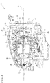
figure 1 shows schematically a three quarter front perspective view of a lighting device according to the invention; -
figure 2 shows in an enlarged scale, a three quarter rear perspective schematic view of a radiator element of one cooled lighting module of the lighting device offigure 1 ; -
figure 3 shows schematically and in perspective view from the rear a cooled lighting module of the lighting device offigure 1 ; and -
figure 4 shows schematically a sectioned side elevation view of the lighting device offigure 1 . - With reference to
figures 1 and4 , reference numeral 1 indicates as a whole a lighting device for a vehicle consisting, in the non-limiting embodiment shown, in a vehicle headlight/headlamp, which is only schematically shown. It is however to be intended that what will be described can be applied to any vehicle lighting device. - The lighting device 1 comprises a generally cup-
shaped housing body 2 designed to be mounted on a vehicle, known and not shown for sake of simplicity. -
Housing body 2 is made of synthetic plastic material by injection molding and has a front inlet opening 3 in use facing opposite to the vehicle and along a driving direction of the vehicle, closed by a transparent cover 4, which may either be a "terse" lens (i.e. without optical functions - as in the preferred example shown) or an optical lens having optical functions, e.g. prismed. - According to the present invention,
housing body 2 carries at the interior thereof at least onelighting module 5 shown in details infigures 3 and4 . Of course, thehousing body 2 may carry within it more than onelighting module 5 or modules similar to module 5 (e.g. two or three, arranged side by side) that may be visible from the outside through the inlet opening 3 and the transparent cover 4. - In the non-limiting example shown (
figure 4 ) the lighting device 1 is equipped with onesingle lighting module 5, which is stationary, and with one or more rotatinglighting modules 11, known and not shown in details for sake of simplicity. - The
modules shaped housing body 2 and the front transparent screen/cover 4 closing the inlet opening 3. - One
lighting module 5 according to the present invention is shown in more details infigure 3 and4 ; according to the invention, thelighting module 5 is a cooled lighting module comprising at least one light source 6 and aradiator element 7 better shown in an enlarged scale infigure 2 . - The
radiator element 7 is operatively associated to the at least one light source 6 to remove the heat generated in use by the at least one light source 6. - In the non-limiting, but preferred, embodiment shown the cooled
lighting module 5 is provided with two light sources 6, both consisting of LEDs; the LEDs 6 are mounted on a printed circuit board 8 also carrying the necessary electronics. The printed circuit board 8 is mounted rigid against theradiator element 7, in thermal contact thereof, e.g. by means of clipping elements and/or of a thermal adhesive. - According to one aspect of the present invention, each cooled
lighting module 5 further comprises adiverter screen element 10 assembled directly onto theradiator element 7, rigid therewith and spaced apart therefrom. - The
diverter screen element 10 delimits together with theradiator element 7 and within the housing body 2 anon-linear channel 12 arranged substantially immediately at the rear of the at least one light source 6. For "immediately at the rear of the at least one light source 6" it is to be intended that thenon-linear channel 12 is divided from the two light sources 6 solely by the printed circuit board 8 to which the light sources 6 are attached and by a substantiallyflat base plate 13 of theradiator element 7, which constitutes one of the lateral walls of thenon-linear channel 12. For "non-linear" it is to be intended thatchannel 12 is not rectilinear, but describes a turn. - The
non-linear channel 12 has a first and a second open end, opposite to each other, indicated respectively with thereference numbers - The second
open end 15 faces the transparent cover or lens 4, as well shown infigure 4 . - According to a strongly preferred feature of the invention, each cooled
lighting module 5 further comprises a motorizedfan 16 of any known and suitable type, operatively associated to theradiator element 7 and designed to generate an air flow F (schematically indicated by the arrows infigure 4 ) within thehousing body 2 to lap against theradiator element 7. - According to a further feature of the invention, the first
open end 14 of thenon-linear channel 12 is arranged immediately in front of thefan 16. - The
fan 16 of each cooledlighting module 5 is arranged at the bottom of thehousing body 2 and at the rear of the respective at least one light source 6, in the embodiment shown immediately at the rear of thebase plate 13 of theradiator element 7, and immediately beneath the firstopen end 14 of thenon-linear channel 12. - The
non-linear channel 12 extends from the bottom upwards so that the secondopen end 15 of thenon-linear channel 12 is arranged above the at least one light source 6. - In particular, the second
open end 15 of thenon-linear channel 12 faces anupper portion 18 of the transparent cover or lens 4 (seefigure 4 ). - The
non-linear channel 12 and the transparent cover or lens 4 are designed such that the air flow F generated by thefan 16 laps against theradiator element 7 in a direction of a development in length of theradiator element 7 itself, namely in a substantially vertical direction, from the bottom upwards. - Moreover, both the
non-linear channel 12 and of the cover or lens 4 are designed so that the air flow F generated by thefan 16 laps against aninner surface 19 of the transparent cover or lens 4 from the top downwards. - As it is well shown in
figure 2 , theradiator element 7 is provided with a plurality of radiatingfins 20 which extend in cantilever manner from thebase plate 13 on a side opposite to the at least one (two on the example shown) light source 6 and towards thediverter screen element 10 for almost the full width of thenon-linear channel 12. With the expression "for almost the full width of thenon-linear channel 12" it is intended that the radiating fins 20 project from thebase plate 13 and towards thediverter screen element 10 for more than two thirds of the total width of thenon-linear channel 12 measured in a direction transverse to, and substantially perpendicular to, thebase plate 13, namely in the plane of the sheet infigure 4 . - The radiating
fins 20 moreover extend in length (i.e. in a direction substantially perpendicular to that of their extension in cantilever fashion from the base plate 13) along the full length of theradiator element 7, in a direction substantially perpendicular to an optical axis O of the cooled lighting module 5 (figure 4 ) along which the light generated by thelighting module 5 is delivered in use. - The diverter screen element is designed such that a cross section of the first
open end 14 of thenon-linear channel 12 is oriented substantially perpendicular to the optical axis 0 and such that thenon-linear channel 12 is curved at right angle in anupper section 21 thereof, so that the cross-section of the secondopen end 15 of thenon-linear channel 12 is oriented substantially parallel to the optical axis O. In particular, theupper section 21 is curves in a continuous manner, according to a radius, since anupper portion 21b of the diverter screen element is shaped curved, according to a substantially cylindrical geometry having a symmetry axis A parallel to thebase plate 13 and perpendicular to theradiating fins 20. - According to the preferred embodiment shown, the
diverter screen element 10 is assembled onto theradiator element 7 by means of removable retaining elements, e.g. byscrews 22, housed inseats 23 provided in thediverter screen element 10. - In particular, the
diverter screen element 10 is assembled onto theradiator element 7 directly on a couple ofradiating fins 20 arranged adjacent oppositelateral sides 23 of theradiator element 7 and each flanked towards the oppositelateral sides 23 of theradiator element 7 by at least another one radiatingfin 20. Such radiatingfins 20 bearing thediverter screen element 10 are provided with internally threadedcylindrical embossment 25 to receive thescrews 22. - The
radiator element 7 is made of a metal alloy, preferably of an aluminum based light alloy, while thediverter screen element 10 is made of a synthetic plastic material, in particular resistant to heat, for example a thermosetting resin. It has been found that the combination of the above two materials gives rise to the best performances and allow an easy assembly and disassembly of thelighting module 5. - Preferably, the printed circuit board 8 with the LEDs 6, the
radiator element 7 and thediverter screen element 10 form a self-supporting unit which may be assembled and disassembled to/from the rest of thelighting device 5 in one single operation; thefan 16, on the contrary, is supported by abottom wall 26 of thehousing body 2 as a separate and independent element. - Last but not least, the
housing body 2 is designed so as to provide anair flow passage 27 for the air flow F all around each at least one cooledlighting module 5. - The
air flow passage 27 connects the secondopen end 15 of thenon-linear channel 12 to the firstopen end 14 thereof, and flanks theinner surface 19 of the transparent cover or lens 4 from the top to the bottom thereof. - Owing to the specific design described above, the heat generated in use by the LEDs 6 is removed immediately and efficiently by means of the
radiator element 7 and, above all, by the air flow F which is directed by thediverter screen element 10 directly and solely through theradiating fins 20 and along a curved trajectory in a turbulent motion, which increase the heat exchange coefficient - Moreover, such heat so efficiently removed is not dispersed within the
housing body 2, but is directed by thediverter screen element 10 against the upper section (the top) of the cover/lens 4; owing to the presence of theair flow passage 27, moreover, the hot air flow F is made to lap the whole surface of the cover/lens 4 from the top downwards: such a direction of lapping allows all the eventual drops of humidity to be efficiently removed since they are made to run along theinner surface 19 towards thebottom wall 26, were they are collected, if not evaporated before. The heat distribution obtainable on the lens/cover 4 owing to thediverter screen element 10, finally, has proved experimentally to be able to efficiently defrost the lens/cover 4 even in cold winters. - All the aims of the invention are therefore accomplished.
Claims (9)
- A lighting device (1) for a vehicle such as a headlight or a headlamp, comprising a cup-shaped housing body (2) designed to be mounted on a vehicle body and at least one cooled lighting module (5) arranged within the housing body facing a front inlet opening (3) thereof closed by a transparent cover or lens (4); each cooled lighting module comprising at least one light source (6) and a radiator element (7) operatively associated to the at least one light source to remove the heat generated in use by the at least one light source; wherein:i)- each cooled lighting module further comprises a diverter screen element (10) assembled directly onto the radiator element (7), rigid therewith and spaced apart therefrom;ii)- the diverter screen element delimiting with the radiator element a non-linear channel (12) arranged immediately at the rear of the at least one light source; andiii)- the non-linear channel (12) having a first and a second open end (14,15), opposite to each other; characterized in thativ)- the non-linear channel (12) is delimited by the diverter screen element within the housing body;v)- the second open end (15) faces the transparent cover or lens (4);vi)- the housing body (2) is designed so as to provide an air flow passage (27) for an air flow (F) all around the at least one cooled lighting module (5),vii)- the air flow passage (27) connecting the second open end (15) of the non-linear channel (12) to the first open end (14) thereof, and flanking an inner surface (19) of the transparent cover or lens (4) from the top to the bottom thereof, so thatviii)- the air flow (F) is made to lap the whole surface of the cover/lens (4) from the top downwards allowing eventual drops of humidity to be efficiently removed.
- A lighting device (1) according to claim 1, characterized in that each cooled lighting module further comprises a fan (16) operatively associated to the radiator element (7) and designed to generate said air flow (F) within the housing body to lap against the radiator element, the first open end (14) of the non-linear channel being arranged immediately in front of the fan (16).
- A lighting device (1) according to claim 2, characterized in that the fan (16) of each cooled lighting module is arranged at the bottom of the housing body and at the rear of the respective at least one light source (6), immediately beneath the first open end (14) of the non-linear channel; the latter extending upwards, the second open end (15) of the non-linear channel being arranged above the at least one light source (6).
- A lighting device (1) according to claim 2 or 3, characterized in that the second open end (15) of the non-linear channel (12) faces an upper portion (18) of the transparent cover or lens, the non-linear channel (12) and the transparent cover or lens (4) being designed such that the air flow generated by the fan (16) laps against the radiator element (7) in a direction of a development in length of the radiator element, from the bottom upwards and against the inner surface (19) of the transparent cover or lens from the top downwards.
- A lighting device (1) according to anyone of the preceding claims, characterized in that the radiator element (7) is provided with a plurality of radiating fins (20) which extend on a side opposite to the at least one light source and towards the diverter screen element (10) for almost the full width of the non-linear channel; the radiating fins extending in length along the full length of (20) the radiator element in a direction substantially perpendicular to an optical axis (0) of the cooled lighting module.
- A lighting device (1) according to claim 5, characterized in that the diverter screen element (10) is designed such that a cross section of the first open end (14) of the non-linear channel is oriented substantially perpendicular to the optical axis (0) and such that the non-linear channel (12) is curved at right angle in an upper section (21) thereof so that the cross-section of the second open (15) end of the non-linear channel is oriented substantially parallel to the optical axis (0).
- A lighting device (1) according to claim 5 or 6, characterized in that the diverter screen element (10) is assembled by means of removable retaining elements (22) directly on a couple of radiating fins (20) arranged adjacent opposite lateral sides (23) of the radiator element and each flanked towards the opposite lateral sides of the radiator element by at least another one radiating fin (20).
- A lighting device (1) according to anyone of the preceding claims, characterized in that the radiator element (7) is made of a metal alloy, preferably of an aluminum based light alloy, and in that the diverter screen element (10) is made of a synthetic plastic material.
- Vehicle provided with a lighting device (1) according to anyone of the preceding claims.
Priority Applications (2)
| Application Number | Priority Date | Filing Date | Title |
|---|---|---|---|
| EP17180838.9A EP3428514B1 (en) | 2017-07-11 | 2017-07-11 | Lighting device for vehicles provided with cooled lighting modules |
| CN201810758103.2A CN109237427B (en) | 2017-07-11 | 2018-07-11 | Vehicle lighting device with cooling lighting module |
Applications Claiming Priority (1)
| Application Number | Priority Date | Filing Date | Title |
|---|---|---|---|
| EP17180838.9A EP3428514B1 (en) | 2017-07-11 | 2017-07-11 | Lighting device for vehicles provided with cooled lighting modules |
Publications (2)
| Publication Number | Publication Date |
|---|---|
| EP3428514A1 EP3428514A1 (en) | 2019-01-16 |
| EP3428514B1 true EP3428514B1 (en) | 2022-01-05 |
Family
ID=59315525
Family Applications (1)
| Application Number | Title | Priority Date | Filing Date |
|---|---|---|---|
| EP17180838.9A Active EP3428514B1 (en) | 2017-07-11 | 2017-07-11 | Lighting device for vehicles provided with cooled lighting modules |
Country Status (2)
| Country | Link |
|---|---|
| EP (1) | EP3428514B1 (en) |
| CN (1) | CN109237427B (en) |
Families Citing this family (2)
| Publication number | Priority date | Publication date | Assignee | Title |
|---|---|---|---|---|
| DE102020210454A1 (en) | 2019-08-27 | 2021-05-12 | Motional AD LLC (n.d.Ges.d. Staates Delaware) | Cooling solutions for autonomous vehicles |
| DE102020121532A1 (en) | 2019-08-29 | 2021-03-04 | Motional AD LLC (n.d.Ges.d. Staates Delaware) | Sensor housing |
Family Cites Families (5)
| Publication number | Priority date | Publication date | Assignee | Title |
|---|---|---|---|---|
| JP5160992B2 (en) | 2008-07-24 | 2013-03-13 | 株式会社小糸製作所 | Vehicle lighting |
| FR2958217B1 (en) * | 2010-04-01 | 2012-05-04 | Peugeot Citroen Automobiles Sa | VEHICLE INTEGRATING A ROAD OF AIR BETWEEN HEADLIGHT AND CABIN |
| US9121561B2 (en) * | 2010-07-26 | 2015-09-01 | Valeo Vision | Optical module of a lighting and/or signaling device for a motor vehicle |
| FR3031572B1 (en) * | 2015-01-09 | 2018-08-10 | Valeo Vision | OPTICAL MODULE FOR VEHICLE PROJECTOR |
| CN206234745U (en) * | 2016-09-27 | 2017-06-09 | 重庆雷嘉光电科技有限公司 | A kind of vehicle and its LED light device |
-
2017
- 2017-07-11 EP EP17180838.9A patent/EP3428514B1/en active Active
-
2018
- 2018-07-11 CN CN201810758103.2A patent/CN109237427B/en active Active
Also Published As
| Publication number | Publication date |
|---|---|
| CN109237427B (en) | 2022-07-05 |
| CN109237427A (en) | 2019-01-18 |
| EP3428514A1 (en) | 2019-01-16 |
Similar Documents
| Publication | Publication Date | Title |
|---|---|---|
| US20130135874A1 (en) | Lamp Housing | |
| US8297805B2 (en) | Device for cooling an optical module for a motor vehicle headlight | |
| CN103339439B (en) | Light emitting semiconductor module and car light | |
| EP3428514B1 (en) | Lighting device for vehicles provided with cooled lighting modules | |
| US8704076B2 (en) | Thermoelectric tempering device | |
| FR2885990A1 (en) | Motor vehicle lighting/indicator lamp with electroluminescent diodes has cooling system formed by fixed and moving radiators and air blower fan | |
| CN101392882A (en) | Vehicle lighting device | |
| ATE553334T1 (en) | HEADLIGHT FOR A MOTOR VEHICLE | |
| US20090133427A1 (en) | No-Frost Cooling Device | |
| CN205051560U (en) | Frequency converter | |
| US20170343182A1 (en) | Lighting and/or signaling device for a motor vehicle, provided with a light module cooled by means of an air flow generator | |
| EP1382472B1 (en) | An air-distribution device for motor vehicles | |
| JP2022128266A (en) | Vehicular headlight | |
| RU194196U1 (en) | Lighting installation | |
| JP2007087665A5 (en) | ||
| EP2952383A1 (en) | Vehicular lighting device | |
| JP4147588B2 (en) | LED cooling module | |
| JP5677105B2 (en) | Vehicle lighting | |
| CN108150962B (en) | Lighting device for a motor vehicle | |
| CN111623313B (en) | Motor vehicle light assembly and method of inhibiting fogging, frosting and/or icing of a lens | |
| CN208935951U (en) | A kind of multi-faceted heat dissipation pa lamp | |
| JP6961891B2 (en) | Vehicle lighting device | |
| DE102007016441B4 (en) | Vehicle light, which is designed as a headlight, with at least one LED as a light source | |
| CN102374631A (en) | Air conditioner with illumination panel and indoor unit of air conditioner | |
| CN102401303A (en) | Vehicle headlight |
Legal Events
| Date | Code | Title | Description |
|---|---|---|---|
| PUAI | Public reference made under article 153(3) epc to a published international application that has entered the european phase |
Free format text: ORIGINAL CODE: 0009012 |
|
| STAA | Information on the status of an ep patent application or granted ep patent |
Free format text: STATUS: THE APPLICATION HAS BEEN PUBLISHED |
|
| AK | Designated contracting states |
Kind code of ref document: A1 Designated state(s): AL AT BE BG CH CY CZ DE DK EE ES FI FR GB GR HR HU IE IS IT LI LT LU LV MC MK MT NL NO PL PT RO RS SE SI SK SM TR |
|
| AX | Request for extension of the european patent |
Extension state: BA ME |
|
| STAA | Information on the status of an ep patent application or granted ep patent |
Free format text: STATUS: REQUEST FOR EXAMINATION WAS MADE |
|
| 17P | Request for examination filed |
Effective date: 20190716 |
|
| RBV | Designated contracting states (corrected) |
Designated state(s): AL AT BE BG CH CY CZ DE DK EE ES FI FR GB GR HR HU IE IS IT LI LT LU LV MC MK MT NL NO PL PT RO RS SE SI SK SM TR |
|
| RAP1 | Party data changed (applicant data changed or rights of an application transferred) |
Owner name: MARELLI AUTOMOTIVE LIGHTING ITALY S.P.A. Owner name: PSA AUTOMOBILES SA |
|
| RAP1 | Party data changed (applicant data changed or rights of an application transferred) |
Owner name: MARELLI AUTOMOTIVE LIGHTING ITALY S.P.A. Owner name: PSA AUTOMOBILES SA |
|
| GRAP | Despatch of communication of intention to grant a patent |
Free format text: ORIGINAL CODE: EPIDOSNIGR1 |
|
| STAA | Information on the status of an ep patent application or granted ep patent |
Free format text: STATUS: GRANT OF PATENT IS INTENDED |
|
| INTG | Intention to grant announced |
Effective date: 20210729 |
|
| GRAS | Grant fee paid |
Free format text: ORIGINAL CODE: EPIDOSNIGR3 |
|
| GRAA | (expected) grant |
Free format text: ORIGINAL CODE: 0009210 |
|
| STAA | Information on the status of an ep patent application or granted ep patent |
Free format text: STATUS: THE PATENT HAS BEEN GRANTED |
|
| AK | Designated contracting states |
Kind code of ref document: B1 Designated state(s): AL AT BE BG CH CY CZ DE DK EE ES FI FR GB GR HR HU IE IS IT LI LT LU LV MC MK MT NL NO PL PT RO RS SE SI SK SM TR |
|
| REG | Reference to a national code |
Ref country code: GB Ref legal event code: FG4D |
|
| REG | Reference to a national code |
Ref country code: CH Ref legal event code: EP |
|
| REG | Reference to a national code |
Ref country code: AT Ref legal event code: REF Ref document number: 1460905 Country of ref document: AT Kind code of ref document: T Effective date: 20220115 |
|
| REG | Reference to a national code |
Ref country code: DE Ref legal event code: R096 Ref document number: 602017051784 Country of ref document: DE |
|
| REG | Reference to a national code |
Ref country code: IE Ref legal event code: FG4D |
|
| REG | Reference to a national code |
Ref country code: LT Ref legal event code: MG9D |
|
| REG | Reference to a national code |
Ref country code: NL Ref legal event code: MP Effective date: 20220105 |
|
| REG | Reference to a national code |
Ref country code: AT Ref legal event code: MK05 Ref document number: 1460905 Country of ref document: AT Kind code of ref document: T Effective date: 20220105 |
|
| PG25 | Lapsed in a contracting state [announced via postgrant information from national office to epo] |
Ref country code: NL Free format text: LAPSE BECAUSE OF FAILURE TO SUBMIT A TRANSLATION OF THE DESCRIPTION OR TO PAY THE FEE WITHIN THE PRESCRIBED TIME-LIMIT Effective date: 20220105 |
|
| PG25 | Lapsed in a contracting state [announced via postgrant information from national office to epo] |
Ref country code: SE Free format text: LAPSE BECAUSE OF FAILURE TO SUBMIT A TRANSLATION OF THE DESCRIPTION OR TO PAY THE FEE WITHIN THE PRESCRIBED TIME-LIMIT Effective date: 20220105 Ref country code: RS Free format text: LAPSE BECAUSE OF FAILURE TO SUBMIT A TRANSLATION OF THE DESCRIPTION OR TO PAY THE FEE WITHIN THE PRESCRIBED TIME-LIMIT Effective date: 20220105 Ref country code: PT Free format text: LAPSE BECAUSE OF FAILURE TO SUBMIT A TRANSLATION OF THE DESCRIPTION OR TO PAY THE FEE WITHIN THE PRESCRIBED TIME-LIMIT Effective date: 20220505 Ref country code: NO Free format text: LAPSE BECAUSE OF FAILURE TO SUBMIT A TRANSLATION OF THE DESCRIPTION OR TO PAY THE FEE WITHIN THE PRESCRIBED TIME-LIMIT Effective date: 20220405 Ref country code: LT Free format text: LAPSE BECAUSE OF FAILURE TO SUBMIT A TRANSLATION OF THE DESCRIPTION OR TO PAY THE FEE WITHIN THE PRESCRIBED TIME-LIMIT Effective date: 20220105 Ref country code: HR Free format text: LAPSE BECAUSE OF FAILURE TO SUBMIT A TRANSLATION OF THE DESCRIPTION OR TO PAY THE FEE WITHIN THE PRESCRIBED TIME-LIMIT Effective date: 20220105 Ref country code: ES Free format text: LAPSE BECAUSE OF FAILURE TO SUBMIT A TRANSLATION OF THE DESCRIPTION OR TO PAY THE FEE WITHIN THE PRESCRIBED TIME-LIMIT Effective date: 20220105 Ref country code: BG Free format text: LAPSE BECAUSE OF FAILURE TO SUBMIT A TRANSLATION OF THE DESCRIPTION OR TO PAY THE FEE WITHIN THE PRESCRIBED TIME-LIMIT Effective date: 20220405 |
|
| PG25 | Lapsed in a contracting state [announced via postgrant information from national office to epo] |
Ref country code: PL Free format text: LAPSE BECAUSE OF FAILURE TO SUBMIT A TRANSLATION OF THE DESCRIPTION OR TO PAY THE FEE WITHIN THE PRESCRIBED TIME-LIMIT Effective date: 20220105 Ref country code: LV Free format text: LAPSE BECAUSE OF FAILURE TO SUBMIT A TRANSLATION OF THE DESCRIPTION OR TO PAY THE FEE WITHIN THE PRESCRIBED TIME-LIMIT Effective date: 20220105 Ref country code: GR Free format text: LAPSE BECAUSE OF FAILURE TO SUBMIT A TRANSLATION OF THE DESCRIPTION OR TO PAY THE FEE WITHIN THE PRESCRIBED TIME-LIMIT Effective date: 20220406 Ref country code: FI Free format text: LAPSE BECAUSE OF FAILURE TO SUBMIT A TRANSLATION OF THE DESCRIPTION OR TO PAY THE FEE WITHIN THE PRESCRIBED TIME-LIMIT Effective date: 20220105 Ref country code: AT Free format text: LAPSE BECAUSE OF FAILURE TO SUBMIT A TRANSLATION OF THE DESCRIPTION OR TO PAY THE FEE WITHIN THE PRESCRIBED TIME-LIMIT Effective date: 20220105 |
|
| PG25 | Lapsed in a contracting state [announced via postgrant information from national office to epo] |
Ref country code: IS Free format text: LAPSE BECAUSE OF FAILURE TO SUBMIT A TRANSLATION OF THE DESCRIPTION OR TO PAY THE FEE WITHIN THE PRESCRIBED TIME-LIMIT Effective date: 20220505 |
|
| REG | Reference to a national code |
Ref country code: DE Ref legal event code: R097 Ref document number: 602017051784 Country of ref document: DE |
|
| PG25 | Lapsed in a contracting state [announced via postgrant information from national office to epo] |
Ref country code: SM Free format text: LAPSE BECAUSE OF FAILURE TO SUBMIT A TRANSLATION OF THE DESCRIPTION OR TO PAY THE FEE WITHIN THE PRESCRIBED TIME-LIMIT Effective date: 20220105 Ref country code: SK Free format text: LAPSE BECAUSE OF FAILURE TO SUBMIT A TRANSLATION OF THE DESCRIPTION OR TO PAY THE FEE WITHIN THE PRESCRIBED TIME-LIMIT Effective date: 20220105 Ref country code: RO Free format text: LAPSE BECAUSE OF FAILURE TO SUBMIT A TRANSLATION OF THE DESCRIPTION OR TO PAY THE FEE WITHIN THE PRESCRIBED TIME-LIMIT Effective date: 20220105 Ref country code: EE Free format text: LAPSE BECAUSE OF FAILURE TO SUBMIT A TRANSLATION OF THE DESCRIPTION OR TO PAY THE FEE WITHIN THE PRESCRIBED TIME-LIMIT Effective date: 20220105 Ref country code: DK Free format text: LAPSE BECAUSE OF FAILURE TO SUBMIT A TRANSLATION OF THE DESCRIPTION OR TO PAY THE FEE WITHIN THE PRESCRIBED TIME-LIMIT Effective date: 20220105 Ref country code: CZ Free format text: LAPSE BECAUSE OF FAILURE TO SUBMIT A TRANSLATION OF THE DESCRIPTION OR TO PAY THE FEE WITHIN THE PRESCRIBED TIME-LIMIT Effective date: 20220105 |
|
| PLBE | No opposition filed within time limit |
Free format text: ORIGINAL CODE: 0009261 |
|
| STAA | Information on the status of an ep patent application or granted ep patent |
Free format text: STATUS: NO OPPOSITION FILED WITHIN TIME LIMIT |
|
| PG25 | Lapsed in a contracting state [announced via postgrant information from national office to epo] |
Ref country code: AL Free format text: LAPSE BECAUSE OF FAILURE TO SUBMIT A TRANSLATION OF THE DESCRIPTION OR TO PAY THE FEE WITHIN THE PRESCRIBED TIME-LIMIT Effective date: 20220105 |
|
| 26N | No opposition filed |
Effective date: 20221006 |
|
| PG25 | Lapsed in a contracting state [announced via postgrant information from national office to epo] |
Ref country code: SI Free format text: LAPSE BECAUSE OF FAILURE TO SUBMIT A TRANSLATION OF THE DESCRIPTION OR TO PAY THE FEE WITHIN THE PRESCRIBED TIME-LIMIT Effective date: 20220105 Ref country code: MC Free format text: LAPSE BECAUSE OF FAILURE TO SUBMIT A TRANSLATION OF THE DESCRIPTION OR TO PAY THE FEE WITHIN THE PRESCRIBED TIME-LIMIT Effective date: 20220105 |
|
| REG | Reference to a national code |
Ref country code: CH Ref legal event code: PL |
|
| REG | Reference to a national code |
Ref country code: BE Ref legal event code: MM Effective date: 20220731 |
|
| PG25 | Lapsed in a contracting state [announced via postgrant information from national office to epo] |
Ref country code: LU Free format text: LAPSE BECAUSE OF NON-PAYMENT OF DUE FEES Effective date: 20220711 Ref country code: LI Free format text: LAPSE BECAUSE OF NON-PAYMENT OF DUE FEES Effective date: 20220731 Ref country code: CH Free format text: LAPSE BECAUSE OF NON-PAYMENT OF DUE FEES Effective date: 20220731 |
|
| PG25 | Lapsed in a contracting state [announced via postgrant information from national office to epo] |
Ref country code: BE Free format text: LAPSE BECAUSE OF NON-PAYMENT OF DUE FEES Effective date: 20220731 |
|
| PG25 | Lapsed in a contracting state [announced via postgrant information from national office to epo] |
Ref country code: IE Free format text: LAPSE BECAUSE OF NON-PAYMENT OF DUE FEES Effective date: 20220711 |
|
| PGFP | Annual fee paid to national office [announced via postgrant information from national office to epo] |
Ref country code: IT Payment date: 20230620 Year of fee payment: 7 Ref country code: FR Payment date: 20230621 Year of fee payment: 7 |
|
| PGFP | Annual fee paid to national office [announced via postgrant information from national office to epo] |
Ref country code: TR Payment date: 20230626 Year of fee payment: 7 |
|
| PGFP | Annual fee paid to national office [announced via postgrant information from national office to epo] |
Ref country code: GB Payment date: 20230620 Year of fee payment: 7 |
|
| PGFP | Annual fee paid to national office [announced via postgrant information from national office to epo] |
Ref country code: DE Payment date: 20230620 Year of fee payment: 7 |
|
| PG25 | Lapsed in a contracting state [announced via postgrant information from national office to epo] |
Ref country code: HU Free format text: LAPSE BECAUSE OF FAILURE TO SUBMIT A TRANSLATION OF THE DESCRIPTION OR TO PAY THE FEE WITHIN THE PRESCRIBED TIME-LIMIT; INVALID AB INITIO Effective date: 20170711 |