EP3428455A1 - Blower - Google Patents
Blower Download PDFInfo
- Publication number
- EP3428455A1 EP3428455A1 EP17763104.1A EP17763104A EP3428455A1 EP 3428455 A1 EP3428455 A1 EP 3428455A1 EP 17763104 A EP17763104 A EP 17763104A EP 3428455 A1 EP3428455 A1 EP 3428455A1
- Authority
- EP
- European Patent Office
- Prior art keywords
- fixing member
- boss
- rotating shaft
- hole
- blower unit
- Prior art date
- Legal status (The legal status is an assumption and is not a legal conclusion. Google has not performed a legal analysis and makes no representation as to the accuracy of the status listed.)
- Withdrawn
Links
Images






Classifications
-
- F—MECHANICAL ENGINEERING; LIGHTING; HEATING; WEAPONS; BLASTING
- F04—POSITIVE - DISPLACEMENT MACHINES FOR LIQUIDS; PUMPS FOR LIQUIDS OR ELASTIC FLUIDS
- F04D—NON-POSITIVE-DISPLACEMENT PUMPS
- F04D29/00—Details, component parts, or accessories
- F04D29/26—Rotors specially for elastic fluids
- F04D29/263—Rotors specially for elastic fluids mounting fan or blower rotors on shafts
-
- F—MECHANICAL ENGINEERING; LIGHTING; HEATING; WEAPONS; BLASTING
- F04—POSITIVE - DISPLACEMENT MACHINES FOR LIQUIDS; PUMPS FOR LIQUIDS OR ELASTIC FLUIDS
- F04D—NON-POSITIVE-DISPLACEMENT PUMPS
- F04D29/00—Details, component parts, or accessories
- F04D29/02—Selection of particular materials
- F04D29/023—Selection of particular materials especially adapted for elastic fluid pumps
-
- F—MECHANICAL ENGINEERING; LIGHTING; HEATING; WEAPONS; BLASTING
- F05—INDEXING SCHEMES RELATING TO ENGINES OR PUMPS IN VARIOUS SUBCLASSES OF CLASSES F01-F04
- F05D—INDEXING SCHEME FOR ASPECTS RELATING TO NON-POSITIVE-DISPLACEMENT MACHINES OR ENGINES, GAS-TURBINES OR JET-PROPULSION PLANTS
- F05D2300/00—Materials; Properties thereof
- F05D2300/40—Organic materials
- F05D2300/44—Resins
Definitions
- the present invention relates to a blower unit having a multi-blade impeller, more particularly to a fixing structure of a blower unit for attaching a resinous fan to a rotating shaft of a motor.
- blower units disclosed in JP-A-2004-3449 (PTL 1) and JP-A-2011-163244 (PTL 2) are known as a blower unit having a resinous fan, especially a blower unit for an in-vehicle air conditioner.
- a small size and a large volume of air are needed for this type of blower unit for an in-vehicle air conditioner so that the blower unit can be installed in a vehicle . Accordingly, this type of blower unit rotates a fan having a smaller distance from a rotating shaft to blades at a higher rotation speed than home blower units (electric fans) . Since noise is caused by the runout of a fan or imbalance in the structure when the rotation speed is high, good balance is needed.
- the fixing means for fixing a fan to a rotating shaft having a circular cross section is also disclosed. That is, a rotating shaft (shaft 21) having a circular cross section is inserted into a boss part of a fan (10) and then press-fitted to a through hole of a resinous fixing member (cap 30) harder than the fan, and the boss part is fitted to the fixing member along the shaft direction of the rotating shaft. Since the hard fixing member is fixed to the rotating shaft, it is possible to prevent the fan having fitted to the fixing member from idly running with respect to the rotating shaft.
- the fixing member Since a part to be fitted to the fan is formed on only one side in the shaft direction of the fixing member in the PTL 1, the fixing member needs to be mounted onto the rotating shaft in a certain direction (certain orientation) so as to be correctly fitted to the fan having been inserted.
- the invention addresses the above situation with an object of obtaining a fixing structure of a blower unit that improves the flexibility of the mount direction of the fixing member in the fixing structure for preventing the idle running of a multi-blade impeller using this fixing member in a blower unit having the structure for fixing a fan to a rotating shaft having a circular cross section.
- the invention of claim 1 is a blower unit 100 including a motor M provided with a rotating shaft 1 having a circular cross section; a resinous fixing member 10 mounted onto the rotating shaft; and a resinous fan 60 having a boss 30 attached to the fixing member, in which the fixing member 10 includes a fixing member through hole 14 to which the rotating shaft 1 is press-fitted, a fixing member first engagement part 15 to be engaged with a boss engagement part 35 provided in the boss 30 in a first mount attitude in which the rotating shaft 1 is press-fitted from one side of the fixing member through hole 14, and a fixing member second engagement part 16 to be engaged with the boss engagement part 35 in a second mount attitude in which the rotating shaft 1 is press-fitted from the other side of the fixing member through hole 14.
- the invention of claim 2 is the blower unit 100 according to claim 1, in which the fixing member through hole 14 has a small-diameter part 14a between the one side and the other side, the fixing member through hole 14 having a diameter smaller than an outer diameter of the rotating shaft 1 at the small-diameter part.
- the invention of claim 3 is the blower unit 100 according to claim 2, in which the fixing member through hole 14 has tapered parts 14b and 14c having diameters tapered gradually from the one side and the other side to the small-diameter part 14a.
- the invention of claim 4 is the blower unit 100 according to any one of claim 1 to 3, in which the fixing member 10 is formed so that the one side is congruous with the other side about a virtual cross section L2 located midway between the end of the one side and the end of the other side.
- the fan 60 can be fixed to the rotating shaft 1 so as not to idly run as in the first mount attitude.
- the fixing member through hole 14 has the small-diameter part 14a between the one side and the other side at which the through hole has a diameter smaller than the outer diameter of the rotating shaft 1, the fixing member 10 can be mounted firmly to the rotating shaft 1 in both the first mount attitude and the second mount attitude of the fixing member 10.
- the fixing member through hole 14 has the tapered parts 14b and 14c having diameters tapered gradually from the one side and the other side to the small-diameter part 14a, the fixing member 10 can be mounted to the rotating shaft 1 relatively easily.
- the rotating shaft 1 can be mounted to the fixing member through hole 14 from any side of the fixing member, thereby improving the flexibility of the mount direction of the fixing member and the convenience of assembly.
- the fixing structure of a blower unit that improves the flexibility of the mount directions of a fixing member in the blower unit having the structure for fixing a fan to a rotating shaft having a circular cross section.
- Fig. 1 to Fig. 14 illustrate components (structural members) of the blower unit according to the first embodiment of the invention.
- the blower unit 100 includes the motor M provided with the rotating shaft 1 having a circular cross section, the resinous fixing member 10 mounted onto the rotating shaft 1, and the resinous fan 60 having a boss 30 attached to the fixing member 10, that is, the resinous fan 60 including a cone 50 extending from the boss 30 and many blades extending from the outer circumferential edge part of the cone 50.
- the fixing member 10 is made of resin having high mechanical strength as in the prior art (for example, the PTL 1 and PTL 2) and that the boss 30 is made of resin having mechanical strength lower than the fixing member 10.
- the fixing member 10 and the boss 30 may be made of resin having approximately the same mechanical strength.
- the fixing member 10 and the fan 60 are formed by a well-known molding method such as injection molding.
- the material of the resin is, for example, polypropylene or ABS resin.
- the fixing member 10 is a cylindrical member and mounted onto the rotating shaft 1 as described above.
- the fan 60 is attached to the fixing member 10 via the boss 30 and the rotation of the rotating shaft 1 is transmitted to the fan 60 via the fixing member 10. Accordingly, the fixing member 10 is firmly fixed to the rotating shaft 1 so as not to slip or move in the shaft direction with respect to the rotating shaft 1.
- the fixing member 10 includes a fixing member first end surface 11 close to the tip of the rotating shaft 1, a fixing member second end surface 12 away from the tip of the rotating shaft, a fixing member outer peripheral surface 13 formed between the fixing member first end surface 11 and the fixing member second end surface 12, the fixing member through hole 14 to which the rotating shaft 1 is press-fitted, the concave or convex fixing member first engagement parts 15 formed on the fixing member outer peripheral surface 13, and the concave or convex fixing member second engagement parts 16 formed in positions different from the positions of the fixing member first engagement parts on the fixing member outer peripheral surface 15.
- the fixing member first engagement parts 15 and the fixing member second engagement parts 16 have concave shapes.
- the fixing member first engagement parts 15 and the fixing member second engagement parts 16 are disposed radially at regular angular intervals about a virtual axial line L1 of the rotating shaft 1.
- each of the fixing member second engagement parts 16 is located midway between each pair of the fixing member first engagement parts 15 (midway between the plurality of fixing member first engagement parts 15 in the circumferential direction of the fixing member outer peripheral surface 13).
- the boss 30 is a cylindrical member, is a part of the fan 60, is made of resin, and is attached to the fixing member 10.
- the boss 30 according to the embodiment includes a boss first end surface 31 close to the tip of the rotating shaft 1, a boss second end surface 32 away from the tip of the rotating shaft 1, a boss outer peripheral surface 33 formed between the boss first end surface 31 and the boss second end surface 32, a boss through hole 34 into which the fixing member 10 is inserted, the boss first engagement parts 35 formed on the inner peripheral surface of the boss through hole 34 and engaged with the fixing member first engagement parts 15, and boss second engagement parts 36 formed on the inner peripheral surface of the boss through hole 34 and engaged with the fixing member second engagement parts 16.
- the boss first end surface 31 is positioned in the upper side of the drawing and the boss second end surface 32 is positioned in the lower side of the drawing.
- the boss first engagement parts 35 and the boss second engagement parts 36 have convex shapes that correspond to the concave shapes of the fixing member first engagement parts 15 and the fixing member second engagement parts 16.
- the boss first engagement parts 35 and the boss second engagement parts 36 are disposed radially at regular angular intervals about the virtual axial line of the rotating shaft 1 so as to correspond to the fixing member first engagement parts 15 and the fixing member second engagement parts 16.
- each of the boss second engagement parts 36 is located midway between each pair of the boss first engagement parts 35 (midway between the plurality of the boss first engagement parts 35 in the circumferential direction of the boss through hole 34).
- the fixing member first engagement part 15 extends from the fixing member first end surface 11 along the shaft direction of the rotating shaft 1 and a fixing member first restricting part 17 is provided at an end thereof.
- the fixing member second engagement part 16 extends from the fixing member second end surface 12 along the shaft direction of the rotating shaft 1 and a fixing member second restricting part 18 is provided at an end thereof.
- boss first engagement part 35 extends from the boss first end surface 31 along the shaft direction of the rotating shaft 1 and a boss first restricting part 37 is provided at an end thereof.
- boss second engagement part 36 extends from a position away from the boss first end surface 31 along the shaft direction of the rotating shaft 1 and a boss second restricting part 38 is provided at an end close to the boss first end surface 31.
- boss second engagement part 36 may extend from the boss second end surface 32 along the shaft direction of the rotating shaft 1 and the boss second restricting part 38 may be provided at an end thereof. Selection is made as appropriate depending on the molding die.
- the fixing member first restricting part 17 and the boss first restricting part 37 form a first restricting mechanism 70 that restricts the range of movement of the boss 30 along the shaft direction of the rotating shaft 1 (see Fig. 13 ).
- the fixing member second restricting part 18 and the boss second restricting part 38 form a second restricting mechanism 80 that restricts the range of movement of the boss 30 along the shaft direction of the rotating shaft 1 (see Fig. 13 ).
- the cone 50 extends from the boss outer peripheral surface 33 corresponding to the fixing member first engagement part 15 or the fixing member second engagement part 16 in the shaft direction of the rotating shaft 1.
- the rotating shaft 1 of the motor is press-fitted and mounted to the fixing member through hole 14 of the fixing member 10 (the rotating shaft 1 is press-fitted and mounted to the fixing member 10), the boss 30 of the fan 60 is attached to the fixing member 10 from the side close to the tip of the rotating shaft 1, that is, the boss 30 is moved from the fixing member first end surface 11, and the engagement parts of the boss 30 are engaged with the engagement parts of the fixing member 10.
- the fan 60 can be fixed to the rotating shaft 1 without idle running.
- the rotational driving force transmitted from the rotating shaft 1 to the fixing member 10 is transmitted radially outward of the rotating shaft from the fixing member 10 to the boss 30 and then transmitted to the cone 50.
- the cone 50 extends radially outward of the rotating shaft 1 from the boss outer peripheral surface 33 corresponding to the fixing member engagement part, the rotational driving force to the cone is also transmitted radially outward of the rotating shaft 1. Since the driving force to the rotating shaft 1, the fixing member 10, the boss 30, and the cone 50 is transmitted radially outward of the rotating shaft 1 and is not transmitted in the direction of the rotating shaft in the blower unit according to the embodiment as described above, the causes of occurrence of runout and imbalance during rotation of the impeller can be eliminated.
- first restricting mechanism 70 formed by the fixing member first restricting part 17 and the boss first restricting part 37 restricts the range of movement of the boss 30 in the direction away from the tip of the rotating shaft 1 and the second restricting mechanism 80 formed by the fixing member second restricting part 18 and the boss second restricting part 38 restricts the range of movement of the boss 30 in the direction toward the tip of the rotating shaft 1.
- first restricting mechanism 70 and the second restricting mechanism 80 are provided as described above, it is possible to prevent the movement of the boss 30 in the shaft direction of the rotating shaft 1 and thereby prevent the movement of the fan 60 in the shaft direction.
- the fixing member first engagement parts 15 and the fixing member second engagement parts 16 are formed in concave shapes and the boss first engagement parts 35 and the boss second engagement parts 36 are formed in convex shapes in the embodiment, the fixing member first engagement parts 15 and the fixing member second engagement parts 16 may be formed in convex shapes and the boss first engagement parts 35 and the boss second engagement parts 36 may be formed in concave shapes.
- the fixing member first restricting parts 17 and the fixing member second restricting parts 18 are preferably present in the same position in the shaft direction of the rotating shaft 1 from the fixing member first end surface 11.
- the boss first restricting parts 37 and the boss second restricting parts 38 are also preferably present in the same position in the shaft direction of the rotating shaft 1 from the boss first end surface 31. This makes it easy to provide a parting line in the same position, facilitates the design of a metal mold, and improves the productivity of the fixing member 10 and the fan 60.
- the fixing member 10 is formed so that the one side is congruous with the other side about the virtual cross section L2 located midway between the fixing member first end surface 11 and the fixing member second end surface 12.
- the fixing member 10 is mounted onto the rotating shaft 1 with the fixing member first end surface 11 facing upward (in the first mount attitude, see particularly Fig. 12 and Fig. 13 ) and then the boss 30 is attached thereto.
- the boss 30 can be attached similarly to the fixing member 10 described above with no difficulty.
- the fixing member 10 is formed congruously about the virtual cross section L2 located midway as described above, since the fixing member 10 may be mounted onto the rotating member 1 from any of the end surfaces, convenience of assembly can be improved.
- the fixing member 10 is formed congruously about the virtual cross section L2 located midway between the fixing member first end surface 11 and the fixing member second end surface 12 as described above when the invention is practiced, although the lengths in the shaft direction of the fixing member first engagement part 15 and the fixing member second engagement part 16 are preferably identical, the invention is not limited to this and the lengths in the shaft direction of the fixing member first engagement part 15 and the fixing member second engagement part 16 may be different as long as there is not difficulty in the rotation of the fan.
- Fig. 15 to Fig. 19 illustrate the fixing member 10 and the boss 30 of the blower unit according to the second embodiment of the invention.
- the blower unit according to the embodiment has the fixing member 10 formed in a cap shape as illustrated in, for example, the PTL 1. That is, the boss 30 of the fan is attached to the rotating shaft 1 and then the fixing member 10 is mounted onto the rotating shaft 1 (the rotating shaft 1 is press-fitted and mounted to the fixing member 10) to fix the boss 30 using the fixing member 10, thereby preventing the fan from rotating with respect to the rotating shaft.
- the blower unit according to the second embodiment of the invention includes the fixing member first engagement parts 15 that are engaged with the boss engagement parts 35 provided in the boss 30 in the first mount attitude in which the fixing member 10 having the fixing member through hole 14 is mounted onto the rotating shaft 1 from one side of the fixing member through hole 14 and the fixing member second engagement parts 16 that are engaged with the boss engagement parts 35 in the second mount attitude in which the fixing member 10 is mounted onto the rotating shaft 1 from the other side of the fixing member through hole 14.
- the fixing member 10 is formed congruously about the virtual cross section L2 located midway in the shaft direction of the fixing member 10 as in the first embodiment.
- the fixing member 10 may be formed plane-symmetrically with respect to the virtual cross section L2.
- the fixing member 10 is mounted with the fixing member first engagement parts 15 facing downward and is engaged with the boss 30 (first mount attitude) .
- the fixing member 10 can be engaged with the boss 30 with the fixing member first engagement parts 16 facing downward with respect to the rotating shaft 1, that is, with the fixing member 10 mounted upside down.
- Fig. 18 illustrates another example of the second embodiment and, in this example, the fixing member through hole 14 is provided with the small-diameter part 14a having a diameter smaller than the outer diameter of the rotating shaft 1 between the one side and the other side.
- the fixing member 10 can be firmly mounted onto the rotating shaft 1 in both the first mount attitude and the second mount attitude of the fixing member 10.
- Fig. 19 illustrates another example of the second embodiment and, in this example, the fixing member through hole 14 is provided with the tapered parts 14b and 14c having diameters tapered gradually from the one side and the other side to the small-diameter part 14a.
- the small-diameter part 14a and the tapered parts 14b and 14c are provided as described above, the work for mounting the fixing member 10 onto the rotating shaft 1 using depression can be performed relatively easily even though the small-diameter part 14a is present.
- the fixing member 10 is formed congruously or plane-symmetrically about the virtual cross section L2 between the end of the one side and the end of the other side as described above, the fixing member 10 can be mounted onto the rotating shaft 1 from any side of the fixing member 10, thereby improving the flexibility of the mount direction of the fixing member and the convenience of assembly.
- the fixing structure of the blower unit for improving the flexibility of the mount direction of the fixing member in the blower unit having the structure in which the fan is fixed to the rotating shaft having a circular cross section.
- blower unit according to the invention has been described above through the first embodiment and the second embodiment, it will be appreciated that the invention is not limited to these two embodiments.
- the blower unit according to the invention can be manufactured industrially and can be preferably used especially for in-vehicle air conditioners.
Landscapes
- Engineering & Computer Science (AREA)
- Mechanical Engineering (AREA)
- General Engineering & Computer Science (AREA)
- Structures Of Non-Positive Displacement Pumps (AREA)
Abstract
Description
- The present invention relates to a blower unit having a multi-blade impeller, more particularly to a fixing structure of a blower unit for attaching a resinous fan to a rotating shaft of a motor.
- For example, blower units disclosed in
JP-A-2004-3449 JP-A-2011-163244 - A small size and a large volume of air are needed for this type of blower unit for an in-vehicle air conditioner so that the blower unit can be installed in a vehicle . Accordingly, this type of blower unit rotates a fan having a smaller distance from a rotating shaft to blades at a higher rotation speed than home blower units (electric fans) . Since noise is caused by the runout of a fan or imbalance in the structure when the rotation speed is high, good balance is needed.
- In the blower unit described in the
PTL 1, the fixing means for fixing a fan to a rotating shaft having a circular cross section is also disclosed. That is, a rotating shaft (shaft 21) having a circular cross section is inserted into a boss part of a fan (10) and then press-fitted to a through hole of a resinous fixing member (cap 30) harder than the fan, and the boss part is fitted to the fixing member along the shaft direction of the rotating shaft. Since the hard fixing member is fixed to the rotating shaft, it is possible to prevent the fan having fitted to the fixing member from idly running with respect to the rotating shaft. -
- PTL 1:
JP-A-2004-3449 - PTL 2:
JP-A-2011-163244 - Since a part to be fitted to the fan is formed on only one side in the shaft direction of the fixing member in the
PTL 1, the fixing member needs to be mounted onto the rotating shaft in a certain direction (certain orientation) so as to be correctly fitted to the fan having been inserted. - Accordingly, it is necessary to determine the mount attitude with respect to the rotating shaft and make adjustment to achieve a regular mount direction in the production process. Since the adjustment of the mount direction of the fixing member requires a certain decision process, there is room for improvement of production efficiency at this point.
- The invention addresses the above situation with an object of obtaining a fixing structure of a blower unit that improves the flexibility of the mount direction of the fixing member in the fixing structure for preventing the idle running of a multi-blade impeller using this fixing member in a blower unit having the structure for fixing a fan to a rotating shaft having a circular cross section.
- The invention of
claim 1 is ablower unit 100 including a motor M provided with a rotatingshaft 1 having a circular cross section; aresinous fixing member 10 mounted onto the rotating shaft; and aresinous fan 60 having aboss 30 attached to the fixing member, in which thefixing member 10 includes a fixing member throughhole 14 to which the rotatingshaft 1 is press-fitted, a fixing memberfirst engagement part 15 to be engaged with aboss engagement part 35 provided in theboss 30 in a first mount attitude in which the rotatingshaft 1 is press-fitted from one side of the fixing member throughhole 14, and a fixing membersecond engagement part 16 to be engaged with theboss engagement part 35 in a second mount attitude in which the rotatingshaft 1 is press-fitted from the other side of the fixing member throughhole 14. - The invention of
claim 2 is theblower unit 100 according toclaim 1, in which the fixing member throughhole 14 has a small-diameter part 14a between the one side and the other side, the fixing member throughhole 14 having a diameter smaller than an outer diameter of the rotatingshaft 1 at the small-diameter part. - The invention of claim 3 is the
blower unit 100 according toclaim 2, in which the fixing member throughhole 14 has taperedparts diameter part 14a. - The invention of claim 4 is the
blower unit 100 according to any one ofclaim 1 to 3, in which thefixing member 10 is formed so that the one side is congruous with the other side about a virtual cross section L2 located midway between the end of the one side and the end of the other side. - According to the invention of
claim 1, when the rotatingshaft 1 is press-fitted from one side of the fixing member throughhole 14 and thefixing member 10 is fixed to the rotating shaft (first mount attitude) and theboss 30 is attached to thefixing member 10, since theengagement part 35 of theboss 30 is fitted to and engaged with the fixing memberfirst engagement part 15 of thefixing member 10, thefan 60 can be fixed to the rotatingshaft 1 so as not to idly run. - In addition, when the rotating
shaft 1 is press-fitted from the other side of the fixing member throughhole 14 and thefixing member 10 is fixed to the rotating shaft (second mount attitude) and theboss 30 is attached to thefixing member 10, since theengagement part 35 of theboss 30 is fitted to and engaged with the fixing membersecond engagement part 16 of thefixing member 10, also in the second mount attitude, thefan 60 can be fixed to the rotatingshaft 1 so as not to idly run as in the first mount attitude. - According to the invention of
claim 2, the fixing member throughhole 14 has the small-diameter part 14a between the one side and the other side at which the through hole has a diameter smaller than the outer diameter of the rotatingshaft 1, thefixing member 10 can be mounted firmly to the rotatingshaft 1 in both the first mount attitude and the second mount attitude of thefixing member 10. - According to the invention of claim 3, since the fixing member through
hole 14 has thetapered parts diameter part 14a, thefixing member 10 can be mounted to the rotatingshaft 1 relatively easily. - According to the invention of claim 4, since the
fixing member 10 is formed so that the one side is congruous with the other side about the virtual cross section L2 located midway between the end of the one side and the end of the other side, the rotatingshaft 1 can be mounted to the fixing member throughhole 14 from any side of the fixing member, thereby improving the flexibility of the mount direction of the fixing member and the convenience of assembly. - As described above, according to the invention, it is possible to obtain the fixing structure of a blower unit that improves the flexibility of the mount directions of a fixing member in the blower unit having the structure for fixing a fan to a rotating shaft having a circular cross section.
-
- [
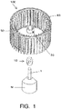
Fig. 1] Fig. 1 is an exploded perspective view illustrating the arrangement state of a boss, a cone, a fan, a fixing member, a rotating shaft, and a motor according to an example of the invention, as seen from obliquely upward. - [
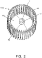
Fig. 2] Fig. 2 is an external perspective view illustrating the mount state of the rotating shaft, the fixing member, and the boss according to the example of the invention, as seen from upward to downward. - [
Fig. 3] Fig. 3 is an enlarged view illustrating the positions of the rotating shaft, the fixing member, and the boss inFig. 2 . - [
Fig. 4] Fig. 4 is an external perspective view illustrating the mount state of the rotating shaft, the fixing member, and the boss according to the example of the invention, as seen from downward to upward. - [
Fig. 5] Fig. 5 is an enlarged view illustrating the positions of the rotating shaft, the fixing member, and the boss inFig. 4 . - [
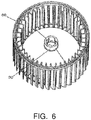
Fig. 6] Fig. 6 is an external perspective view illustrating the boss, the cone, and the fan according to the example of the invention, as seen from upward to downward. - [
Fig. 7] Fig. 7 is an enlarged view illustrating the position of the boss inFig. 6 . - [
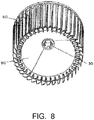
Fig. 8] Fig. 8 is an external perspective view illustrating the boss, the cone, and the fan according to the example of the invention, as seen from downward to upward. - [
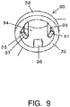
Fig. 9] Fig. 9 is an enlarged view illustrating the position of the boss inFig. 8 . - [
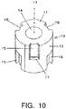
Fig. 10] Fig. 10 is an external perspective view illustrating the fixing member according to the example of the invention as seen from obliquely upward. - [
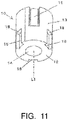
Fig. 11] Fig. 11 is an external perspective view illustrating the fixing member according to the example of the invention as seen from obliquely downward. - [
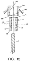
Fig. 12] Fig. 12 is a longitudinal sectional view illustrating, from the top, the boss, the fixing member in the first mount attitude, and the rotating shaft according to the example of the invention in the state in which they are separated from each other. - [
Fig. 13] Fig. 13 is a longitudinal sectional view illustrating the boss, the fixing member in the first mount attitude, and the rotating shaft inFig. 12 in the state in which they are combined with each other. - [
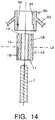
Fig. 14] Fig. 14 is a longitudinal sectional view illustrating, from the top, the boss, the fixing member in the second mount attitude, and the rotating shaft according to the example of the invention in the state in which they are separated from each other. - [
Fig. 15] Fig. 15 is an exploded perspective view illustrating the arrangement state of a fixing member, a boss, a cone, a fan, a rotating shaft, and a motor according to another example of the invention, as seen from obliquely upward. - [
Fig. 16] Fig. 16 is a longitudinal sectional view illustrating, from the top, the fixing member in the first mount attitude, the boss, and the rotating shaft according to the other example of the invention in the state in which they are separated from each other. - [
Fig. 17] Fig. 17 is a longitudinal sectional view illustrating the fixing member in a first press-fitting attitude, the boss, and the rotating shaft inFig. 16 in the state in which they are combined with each other. - [
Fig. 18] Fig. 18 is a longitudinal sectional view illustrating, from the top, a fixing member in a second press-fitting attitude, a boss, and a rotating shaft according to another example of the invention in the state in which they are separated from each other. - [
Fig. 19] Fig. 19 is a longitudinal sectional view illustrating, from the top, a fixing member in the first press-fitting attitude, a boss, and a rotating shaft according to still another example in the state in which they are separated from each other. - An aspect of the invention will be described below with reference to the attached drawings. The embodiments described below are examples of the invention and the invention is not limited to the following embodiments. It should be noted that components having the same reference numerals are identical to each other in this description and the drawing. In addition, various modifications can be made as long as the working effect of the invention is obtained.
-
Fig. 1 to Fig. 14 illustrate components (structural members) of the blower unit according to the first embodiment of the invention. Theblower unit 100 according to the embodiment includes the motor M provided with the rotatingshaft 1 having a circular cross section, theresinous fixing member 10 mounted onto therotating shaft 1, and theresinous fan 60 having aboss 30 attached to thefixing member 10, that is, theresinous fan 60 including acone 50 extending from theboss 30 and many blades extending from the outer circumferential edge part of thecone 50. It should be noted that thefixing member 10 is made of resin having high mechanical strength as in the prior art (for example, thePTL 1 and PTL 2) and that theboss 30 is made of resin having mechanical strength lower than thefixing member 10. Alternatively, thefixing member 10 and theboss 30 may be made of resin having approximately the same mechanical strength. In addition, thefixing member 10 and thefan 60 are formed by a well-known molding method such as injection molding. The material of the resin is, for example, polypropylene or ABS resin. - The
fixing member 10 is a cylindrical member and mounted onto the rotatingshaft 1 as described above. Thefan 60 is attached to thefixing member 10 via theboss 30 and the rotation of the rotatingshaft 1 is transmitted to thefan 60 via thefixing member 10. Accordingly, thefixing member 10 is firmly fixed to the rotatingshaft 1 so as not to slip or move in the shaft direction with respect to the rotatingshaft 1. - In addition, as illustrated in
Fig. 10 andFig. 11 , thefixing member 10 includes a fixing memberfirst end surface 11 close to the tip of the rotatingshaft 1, a fixing membersecond end surface 12 away from the tip of the rotating shaft, a fixing member outerperipheral surface 13 formed between the fixing memberfirst end surface 11 and the fixing membersecond end surface 12, the fixing member throughhole 14 to which the rotatingshaft 1 is press-fitted, the concave or convex fixing memberfirst engagement parts 15 formed on the fixing member outerperipheral surface 13, and the concave or convex fixing membersecond engagement parts 16 formed in positions different from the positions of the fixing member first engagement parts on the fixing member outerperipheral surface 15. - In the fixing
member 10 according to the embodiment, the fixing memberfirst engagement parts 15 and the fixing membersecond engagement parts 16 have concave shapes. In addition, the fixing memberfirst engagement parts 15 and the fixing membersecond engagement parts 16 are disposed radially at regular angular intervals about a virtual axial line L1 of therotating shaft 1. In the disposition aspect of these engagement parts, each of the fixing membersecond engagement parts 16 is located midway between each pair of the fixing member first engagement parts 15 (midway between the plurality of fixing memberfirst engagement parts 15 in the circumferential direction of the fixing member outer peripheral surface 13). - The
boss 30 is a cylindrical member, is a part of thefan 60, is made of resin, and is attached to the fixingmember 10. As illustrated inFig. 7 andFig. 9 , theboss 30 according to the embodiment includes a bossfirst end surface 31 close to the tip of therotating shaft 1, a bosssecond end surface 32 away from the tip of therotating shaft 1, a boss outerperipheral surface 33 formed between the bossfirst end surface 31 and the bosssecond end surface 32, a boss throughhole 34 into which the fixingmember 10 is inserted, the bossfirst engagement parts 35 formed on the inner peripheral surface of the boss throughhole 34 and engaged with the fixing memberfirst engagement parts 15, and bosssecond engagement parts 36 formed on the inner peripheral surface of the boss throughhole 34 and engaged with the fixing membersecond engagement parts 16. In the embodiment, the bossfirst end surface 31 is positioned in the upper side of the drawing and the bosssecond end surface 32 is positioned in the lower side of the drawing. - In the
boss 30 according to the embodiment, the bossfirst engagement parts 35 and the bosssecond engagement parts 36 have convex shapes that correspond to the concave shapes of the fixing memberfirst engagement parts 15 and the fixing membersecond engagement parts 16. In addition, the bossfirst engagement parts 35 and the bosssecond engagement parts 36 are disposed radially at regular angular intervals about the virtual axial line of therotating shaft 1 so as to correspond to the fixing memberfirst engagement parts 15 and the fixing membersecond engagement parts 16. As in the fixingmember 10, in the disposition aspect of these parts, each of the bosssecond engagement parts 36 is located midway between each pair of the boss first engagement parts 35 (midway between the plurality of the bossfirst engagement parts 35 in the circumferential direction of the boss through hole 34). - In the embodiment, as illustrated in
Fig. 10 andFig. 11 in detail, the fixing memberfirst engagement part 15 extends from the fixing memberfirst end surface 11 along the shaft direction of therotating shaft 1 and a fixing member first restrictingpart 17 is provided at an end thereof. In addition, the fixing membersecond engagement part 16 extends from the fixing membersecond end surface 12 along the shaft direction of therotating shaft 1 and a fixing member second restrictingpart 18 is provided at an end thereof. - In contrast, the boss
first engagement part 35 extends from the bossfirst end surface 31 along the shaft direction of therotating shaft 1 and a boss first restrictingpart 37 is provided at an end thereof. In addition, the bosssecond engagement part 36 extends from a position away from the bossfirst end surface 31 along the shaft direction of therotating shaft 1 and a boss second restrictingpart 38 is provided at an end close to the bossfirst end surface 31. It should be noted that the bosssecond engagement part 36 may extend from the bosssecond end surface 32 along the shaft direction of therotating shaft 1 and the boss second restrictingpart 38 may be provided at an end thereof. Selection is made as appropriate depending on the molding die. - As described in detail later, the fixing member first restricting
part 17 and the boss first restrictingpart 37 form a first restrictingmechanism 70 that restricts the range of movement of theboss 30 along the shaft direction of the rotating shaft 1 (seeFig. 13 ). Similarly, the fixing member second restrictingpart 18 and the boss second restrictingpart 38 form a second restricting mechanism 80 that restricts the range of movement of theboss 30 along the shaft direction of the rotating shaft 1 (seeFig. 13 ). - In the embodiment, the
cone 50 extends from the boss outerperipheral surface 33 corresponding to the fixing memberfirst engagement part 15 or the fixing membersecond engagement part 16 in the shaft direction of therotating shaft 1. - In the
blower unit 100 according to the embodiment, therotating shaft 1 of the motor is press-fitted and mounted to the fixing member throughhole 14 of the fixing member 10 (therotating shaft 1 is press-fitted and mounted to the fixing member 10), theboss 30 of thefan 60 is attached to the fixingmember 10 from the side close to the tip of therotating shaft 1, that is, theboss 30 is moved from the fixing memberfirst end surface 11, and the engagement parts of theboss 30 are engaged with the engagement parts of the fixingmember 10. - When the
boss 30 is moved from the fixing memberfirst end surface 11 of the fixingmember 10, positioning is performed so that the bossfirst engagement parts 35 of theboss 30 correspond to the fixing memberfirst engagement parts 15 and the bosssecond engagement parts 36 correspond to the fixing membersecond engagement parts 16 in the shaft direction, and the bosssecond engagement parts 36 are moved so as to make sliding contact with the fixing member outerperipheral surface 13 while the bosssecond engagement parts 36 formed in, for example, a well-known hook are pressed. Then, the bossfirst engagement parts 35 are fitted to and engaged with the fixing memberfirst engagement parts 15 and the bosssecond engagement parts 36 are fitted to and engaged with the fixing membersecond engagement parts 16. - Since the boss
first engagement parts 35 are recess-projection fitted to and engaged with the fixing memberfirst engagement parts 15 and the bosssecond engagement parts 36 are recess-projection fitted to and engaged with the fixing membersecond engagement parts 16 as described above, thefan 60 can be fixed to therotating shaft 1 without idle running. - In the blower unit according to the embodiment, the rotational driving force transmitted from the
rotating shaft 1 to the fixingmember 10 is transmitted radially outward of the rotating shaft from the fixingmember 10 to theboss 30 and then transmitted to thecone 50. In addition, since thecone 50 extends radially outward of therotating shaft 1 from the boss outerperipheral surface 33 corresponding to the fixing member engagement part, the rotational driving force to the cone is also transmitted radially outward of therotating shaft 1. Since the driving force to therotating shaft 1, the fixingmember 10, theboss 30, and thecone 50 is transmitted radially outward of therotating shaft 1 and is not transmitted in the direction of the rotating shaft in the blower unit according to the embodiment as described above, the causes of occurrence of runout and imbalance during rotation of the impeller can be eliminated. - In addition, the above-described first restricting
mechanism 70 formed by the fixing member first restrictingpart 17 and the boss first restrictingpart 37 according to the embodiment restricts the range of movement of theboss 30 in the direction away from the tip of therotating shaft 1 and the second restricting mechanism 80 formed by the fixing member second restrictingpart 18 and the boss second restrictingpart 38 restricts the range of movement of theboss 30 in the direction toward the tip of therotating shaft 1. - Since the first restricting
mechanism 70 and the second restricting mechanism 80 are provided as described above, it is possible to prevent the movement of theboss 30 in the shaft direction of therotating shaft 1 and thereby prevent the movement of thefan 60 in the shaft direction. - Although the fixing member
first engagement parts 15 and the fixing membersecond engagement parts 16 are formed in concave shapes and the bossfirst engagement parts 35 and the bosssecond engagement parts 36 are formed in convex shapes in the embodiment, the fixing memberfirst engagement parts 15 and the fixing membersecond engagement parts 16 may be formed in convex shapes and the bossfirst engagement parts 35 and the bosssecond engagement parts 36 may be formed in concave shapes. - In addition, the fixing member first restricting
parts 17 and the fixing member second restrictingparts 18 are preferably present in the same position in the shaft direction of therotating shaft 1 from the fixing memberfirst end surface 11. In addition, the boss first restrictingparts 37 and the boss second restrictingparts 38 are also preferably present in the same position in the shaft direction of therotating shaft 1 from the bossfirst end surface 31. This makes it easy to provide a parting line in the same position, facilitates the design of a metal mold, and improves the productivity of the fixingmember 10 and thefan 60. - In the first embodiment of the invention described above, the fixing
member 10 is formed so that the one side is congruous with the other side about the virtual cross section L2 located midway between the fixing memberfirst end surface 11 and the fixing membersecond end surface 12. In the example in the first embodiment illustrated in the drawing, the fixingmember 10 is mounted onto therotating shaft 1 with the fixing memberfirst end surface 11 facing upward (in the first mount attitude, see particularlyFig. 12 andFig. 13 ) and then theboss 30 is attached thereto. - In contrast, even when the fixing
member 10 is mounted onto therotating shaft 1 upside down, that is, the fixingmember 10 is mounted with the fixing membersecond end surface 12 facing upward with respect to the rotating shaft 1 (in the second mount attitude) as illustrated inFig. 14 , theboss 30 can be attached similarly to the fixingmember 10 described above with no difficulty. - If the fixing
member 10 is formed congruously about the virtual cross section L2 located midway as described above, since the fixingmember 10 may be mounted onto the rotatingmember 1 from any of the end surfaces, convenience of assembly can be improved. - Since the fixing
member 10 is formed congruously about the virtual cross section L2 located midway between the fixing memberfirst end surface 11 and the fixing membersecond end surface 12 as described above when the invention is practiced, although the lengths in the shaft direction of the fixing memberfirst engagement part 15 and the fixing membersecond engagement part 16 are preferably identical, the invention is not limited to this and the lengths in the shaft direction of the fixing memberfirst engagement part 15 and the fixing membersecond engagement part 16 may be different as long as there is not difficulty in the rotation of the fan. - Next, the second embodiment of the invention will be described.
-
Fig. 15 to Fig. 19 illustrate the fixingmember 10 and theboss 30 of the blower unit according to the second embodiment of the invention. The blower unit according to the embodiment has the fixingmember 10 formed in a cap shape as illustrated in, for example, thePTL 1. That is, theboss 30 of the fan is attached to therotating shaft 1 and then the fixingmember 10 is mounted onto the rotating shaft 1 (therotating shaft 1 is press-fitted and mounted to the fixing member 10) to fix theboss 30 using the fixingmember 10, thereby preventing the fan from rotating with respect to the rotating shaft. - As in the first embodiment, the blower unit according to the second embodiment of the invention includes the fixing member
first engagement parts 15 that are engaged with theboss engagement parts 35 provided in theboss 30 in the first mount attitude in which the fixingmember 10 having the fixing member throughhole 14 is mounted onto therotating shaft 1 from one side of the fixing member throughhole 14 and the fixing membersecond engagement parts 16 that are engaged with theboss engagement parts 35 in the second mount attitude in which the fixingmember 10 is mounted onto therotating shaft 1 from the other side of the fixing member throughhole 14. - Also in the blower unit according to the second embodiment, the fixing
member 10 is formed congruously about the virtual cross section L2 located midway in the shaft direction of the fixingmember 10 as in the first embodiment. In addition, the fixingmember 10 may be formed plane-symmetrically with respect to the virtual cross section L2. In the example illustrated in the drawings (Fig. 16 andFig. 17 ) in the second embodiment, the fixingmember 10 is mounted with the fixing memberfirst engagement parts 15 facing downward and is engaged with the boss 30 (first mount attitude) . - In addition, as the aspect in which numerals 15 and 16 are surrounded by parentheses in
Fig. 16 andFig. 17 , the fixingmember 10 can be engaged with theboss 30 with the fixing memberfirst engagement parts 16 facing downward with respect to therotating shaft 1, that is, with the fixingmember 10 mounted upside down. -
Fig. 18 illustrates another example of the second embodiment and, in this example, the fixing member throughhole 14 is provided with the small-diameter part 14a having a diameter smaller than the outer diameter of therotating shaft 1 between the one side and the other side. - Since the small-
diameter part 14a is provided, the fixingmember 10 can be firmly mounted onto therotating shaft 1 in both the first mount attitude and the second mount attitude of the fixingmember 10. -
Fig. 19 illustrates another example of the second embodiment and, in this example, the fixing member throughhole 14 is provided with the taperedparts diameter part 14a. - Since the small-
diameter part 14a and the taperedparts member 10 onto therotating shaft 1 using depression can be performed relatively easily even though the small-diameter part 14a is present. - In the blower unit according to the second embodiment described above, since the fixing
member 10 is formed congruously or plane-symmetrically about the virtual cross section L2 between the end of the one side and the end of the other side as described above, the fixingmember 10 can be mounted onto therotating shaft 1 from any side of the fixingmember 10, thereby improving the flexibility of the mount direction of the fixing member and the convenience of assembly. - As described above, according to the first embodiment and the second embodiment of the invention, it is possible to obtain the fixing structure of the blower unit for improving the flexibility of the mount direction of the fixing member in the blower unit having the structure in which the fan is fixed to the rotating shaft having a circular cross section.
- Although the blower unit according to the invention has been described above through the first embodiment and the second embodiment, it will be appreciated that the invention is not limited to these two embodiments.
- The blower unit according to the invention can be manufactured industrially and can be preferably used especially for in-vehicle air conditioners.
-
- M:
- motor
- 1:
- rotating shaft
- 10:
- fixing member
- 11:
- fixing member first end surface
- 12:
- fixing member second end surface
- 13:
- fixing member outer peripheral surface
- 14:
- fixing member through hole
- 14a:
- small-diameter part
- 14b:
- tapered part
- 14c:
- tapered part
- 15:
- fixing member first engagement part
- 16:
- fixing member second engagement part
- 17:
- fixing member first restricting part
- 18:
- fixing member second restricting part
- 30:
- boss
- 31:
- boss first end surface
- 32:
- boss second end surface
- 33:
- boss outer peripheral surface
- 34:
- boss through hole
- 35:
- boss first engagement part
- 36:
- boss second engagement part
- 37:
- boss first restricting part
- 38:
- boss second restricting part
- 50:
- cone
- 60:
- fan
- 70:
- first restricting mechanism
- 80:
- second restricting mechanism
- 100:
- blower unit
- L1:
- virtual axial line of rotating shaft
- L2:
- virtual cross section
Claims (4)
- A blower unit 100 comprising:a motor M provided with a rotating shaft 1 having a circular cross section;a resinous fixing member 10 mounted onto the rotating shaft; anda resinous fan 60 having a boss 30 attached to the fixing member,wherein the fixing member 10 includes
a fixing member through hole 14 to which the rotating shaft 1 is press-fitted,
a fixing member first engagement part 15 to be engaged with a boss engagement part 35 provided in the boss 30 in a first mount attitude in which the rotating shaft 1 is press-fitted from one side of the fixing member through hole 14, and
a fixing member second engagement part 16 to be engaged with the boss engagement part 35 in a second mount attitude in which the rotating shaft 1 is press-fitted from the other side of the fixing member through hole 14. - The blower unit 100 according to claim 1,
wherein the fixing member through hole 14 has a small-diameter part 14a between the one side and the other side, the fixing member through hole 14 having a diameter smaller than an outer diameter of the rotating shaft 1 at the small-diameter part. - The blower unit 100 according to claim 2,
wherein the fixing member through hole 14 has tapered parts 14b and 14c having diameters tapered gradually from the one side and the other side to the small-diameter part 14a. - The blower unit 100 according to any one of claims 1 to 3,
wherein the fixing member 10 is formed so that the one side is congruous with the other side about a virtual cross section L2 located midway between the end of the one side and the end of the other side.
Applications Claiming Priority (2)
| Application Number | Priority Date | Filing Date | Title |
|---|---|---|---|
| JP2016044111 | 2016-03-08 | ||
| PCT/JP2017/008440 WO2017154764A1 (en) | 2016-03-08 | 2017-03-03 | Blower |
Publications (2)
| Publication Number | Publication Date |
|---|---|
| EP3428455A1 true EP3428455A1 (en) | 2019-01-16 |
| EP3428455A4 EP3428455A4 (en) | 2019-11-13 |
Family
ID=59790597
Family Applications (1)
| Application Number | Title | Priority Date | Filing Date |
|---|---|---|---|
| EP17763104.1A Withdrawn EP3428455A4 (en) | 2016-03-08 | 2017-03-03 | BLOWER |
Country Status (4)
| Country | Link |
|---|---|
| EP (1) | EP3428455A4 (en) |
| JP (1) | JPWO2017154764A1 (en) |
| CN (1) | CN108713102B (en) |
| WO (1) | WO2017154764A1 (en) |
Families Citing this family (2)
| Publication number | Priority date | Publication date | Assignee | Title |
|---|---|---|---|---|
| JP2022061799A (en) * | 2020-10-07 | 2022-04-19 | 株式会社デンソー | Air blower |
| CN112797022B (en) * | 2020-12-21 | 2022-06-28 | 珠海格力电器股份有限公司 | Fan blade assembly and motor with same |
Family Cites Families (14)
| Publication number | Priority date | Publication date | Assignee | Title |
|---|---|---|---|---|
| US2702087A (en) * | 1951-03-26 | 1955-02-15 | Schwitzer Cummins Company | Fan assembly |
| DE7913075U1 (en) * | 1979-05-05 | 1979-08-16 | Papst-Motoren Kg, 7742 St Georgen | FAN WITH TUBE DRIVE MOTOR |
| JPH03102094U (en) * | 1990-02-01 | 1991-10-24 | ||
| US6200098B1 (en) * | 1999-07-01 | 2001-03-13 | Behr America, Inc. | Speed limited fan |
| JP3843883B2 (en) * | 2002-04-22 | 2006-11-08 | 株式会社デンソー | Blower and blower cap manufacturing method |
| CN2563337Y (en) * | 2002-08-01 | 2003-07-30 | 林三原 | Assembly structure of cooling fan |
| JP3849664B2 (en) * | 2003-04-09 | 2006-11-22 | 株式会社デンソー | Blower |
| CN2628760Y (en) * | 2003-06-02 | 2004-07-28 | 奇鋐科技股份有限公司 | The combination device of the hub and the shaft center of the fan wheel |
| JP5396868B2 (en) * | 2009-01-16 | 2014-01-22 | パナソニック株式会社 | Blower |
| DE102011086379A1 (en) * | 2011-11-15 | 2013-05-16 | Robert Bosch Gmbh | Fan module of air conditioning system for motor car, has fan wheel whose hub is arranged on outside of externally polygonal shaped portion arranged opposite to the steel sleeve |
| CN202732499U (en) * | 2012-06-20 | 2013-02-13 | 重庆润通动力有限公司 | Mounting structure for cooling fan of generator |
| FR3022579B1 (en) * | 2014-06-23 | 2018-11-30 | Carrier Corporation | FASTENING RING FOR AIR TREATMENT UNIT TURBINE WHEEL AND AIR TREATMENT UNIT COMPRISING SUCH A FIXING ELEMENT |
| JP6366389B2 (en) * | 2014-07-03 | 2018-08-01 | 株式会社日本クライメイトシステムズ | Fan mounting structure |
| JP6340281B2 (en) * | 2014-08-04 | 2018-06-06 | 株式会社日本クライメイトシステムズ | Fan mounting structure |
-
2017
- 2017-03-03 EP EP17763104.1A patent/EP3428455A4/en not_active Withdrawn
- 2017-03-03 CN CN201780014853.2A patent/CN108713102B/en not_active Expired - Fee Related
- 2017-03-03 JP JP2018504442A patent/JPWO2017154764A1/en active Pending
- 2017-03-03 WO PCT/JP2017/008440 patent/WO2017154764A1/en not_active Ceased
Also Published As
| Publication number | Publication date |
|---|---|
| WO2017154764A1 (en) | 2017-09-14 |
| EP3428455A4 (en) | 2019-11-13 |
| JPWO2017154764A1 (en) | 2019-01-10 |
| CN108713102B (en) | 2019-11-26 |
| CN108713102A (en) | 2018-10-26 |
Similar Documents
| Publication | Publication Date | Title |
|---|---|---|
| CN106460866B (en) | Fan installation structure | |
| EP3296572A1 (en) | Fan head part, vertical type and wall-mounted type fans, household appliance and air blowing method | |
| US20130209294A1 (en) | Fan | |
| CN204025148U (en) | Centrifugal fan | |
| JP6282541B2 (en) | Centrifugal fan | |
| US9537373B2 (en) | Alternator fan | |
| JP6333102B2 (en) | Centrifugal fan | |
| US10797539B2 (en) | Fan rotor | |
| US11542954B2 (en) | Housing produced in one working step | |
| TWI479086B (en) | Cooling fan | |
| JP5758600B2 (en) | Fan press hub | |
| CN108713102B (en) | Pressure fan | |
| CN110714936A (en) | Impeller | |
| KR101528877B1 (en) | Hub assembly for fan | |
| CN109072936B (en) | Air blower | |
| EP4155548A1 (en) | Axial fan | |
| US20170211585A1 (en) | Double inlet blower wheel | |
| US20200381978A1 (en) | Motor and electrical device including same | |
| CN206481144U (en) | Motor and the electric product with the motor | |
| JP6348896B2 (en) | Rotor and fan device including the rotor | |
| CN105896817B (en) | A kind of disjunctor wind wheel | |
| JP2007278193A (en) | Blower | |
| JP5973539B2 (en) | Press hub for fans | |
| JP2020012382A (en) | Impeller and fan device | |
| JP2011223660A (en) | Motor |
Legal Events
| Date | Code | Title | Description |
|---|---|---|---|
| STAA | Information on the status of an ep patent application or granted ep patent |
Free format text: STATUS: THE INTERNATIONAL PUBLICATION HAS BEEN MADE |
|
| PUAI | Public reference made under article 153(3) epc to a published international application that has entered the european phase |
Free format text: ORIGINAL CODE: 0009012 |
|
| STAA | Information on the status of an ep patent application or granted ep patent |
Free format text: STATUS: REQUEST FOR EXAMINATION WAS MADE |
|
| 17P | Request for examination filed |
Effective date: 20181010 |
|
| AK | Designated contracting states |
Kind code of ref document: A1 Designated state(s): AL AT BE BG CH CY CZ DE DK EE ES FI FR GB GR HR HU IE IS IT LI LT LU LV MC MK MT NL NO PL PT RO RS SE SI SK SM TR |
|
| AX | Request for extension of the european patent |
Extension state: BA ME |
|
| DAV | Request for validation of the european patent (deleted) | ||
| DAX | Request for extension of the european patent (deleted) | ||
| A4 | Supplementary search report drawn up and despatched |
Effective date: 20191010 |
|
| RIC1 | Information provided on ipc code assigned before grant |
Ipc: F04D 29/02 20060101ALI20191004BHEP Ipc: F04D 29/26 20060101AFI20191004BHEP |
|
| STAA | Information on the status of an ep patent application or granted ep patent |
Free format text: STATUS: EXAMINATION IS IN PROGRESS |
|
| 17Q | First examination report despatched |
Effective date: 20211020 |
|
| STAA | Information on the status of an ep patent application or granted ep patent |
Free format text: STATUS: THE APPLICATION IS DEEMED TO BE WITHDRAWN |
|
| 18D | Application deemed to be withdrawn |
Effective date: 20220301 |