EP3428403A1 - Stator vane assembly for a gas turbine engine and method of assembling the same - Google Patents
Stator vane assembly for a gas turbine engine and method of assembling the same Download PDFInfo
- Publication number
- EP3428403A1 EP3428403A1 EP18179562.6A EP18179562A EP3428403A1 EP 3428403 A1 EP3428403 A1 EP 3428403A1 EP 18179562 A EP18179562 A EP 18179562A EP 3428403 A1 EP3428403 A1 EP 3428403A1
- Authority
- EP
- European Patent Office
- Prior art keywords
- wedge
- vane
- clip
- diameter shroud
- gas turbine
- Prior art date
- Legal status (The legal status is an assumption and is not a legal conclusion. Google has not performed a legal analysis and makes no representation as to the accuracy of the status listed.)
- Granted
Links
Images


Classifications
-
- F—MECHANICAL ENGINEERING; LIGHTING; HEATING; WEAPONS; BLASTING
- F01—MACHINES OR ENGINES IN GENERAL; ENGINE PLANTS IN GENERAL; STEAM ENGINES
- F01D—NON-POSITIVE DISPLACEMENT MACHINES OR ENGINES, e.g. STEAM TURBINES
- F01D9/00—Stators
- F01D9/02—Nozzles; Nozzle boxes; Stator blades; Guide conduits, e.g. individual nozzles
- F01D9/04—Nozzles; Nozzle boxes; Stator blades; Guide conduits, e.g. individual nozzles forming ring or sector
- F01D9/042—Nozzles; Nozzle boxes; Stator blades; Guide conduits, e.g. individual nozzles forming ring or sector fixing blades to stators
-
- F—MECHANICAL ENGINEERING; LIGHTING; HEATING; WEAPONS; BLASTING
- F01—MACHINES OR ENGINES IN GENERAL; ENGINE PLANTS IN GENERAL; STEAM ENGINES
- F01D—NON-POSITIVE DISPLACEMENT MACHINES OR ENGINES, e.g. STEAM TURBINES
- F01D9/00—Stators
- F01D9/02—Nozzles; Nozzle boxes; Stator blades; Guide conduits, e.g. individual nozzles
- F01D9/04—Nozzles; Nozzle boxes; Stator blades; Guide conduits, e.g. individual nozzles forming ring or sector
- F01D9/041—Nozzles; Nozzle boxes; Stator blades; Guide conduits, e.g. individual nozzles forming ring or sector using blades
-
- F—MECHANICAL ENGINEERING; LIGHTING; HEATING; WEAPONS; BLASTING
- F04—POSITIVE - DISPLACEMENT MACHINES FOR LIQUIDS; PUMPS FOR LIQUIDS OR ELASTIC FLUIDS
- F04D—NON-POSITIVE-DISPLACEMENT PUMPS
- F04D29/00—Details, component parts, or accessories
- F04D29/40—Casings; Connections of working fluid
- F04D29/52—Casings; Connections of working fluid for axial pumps
- F04D29/54—Fluid-guiding means, e.g. diffusers
- F04D29/541—Specially adapted for elastic fluid pumps
- F04D29/542—Bladed diffusers
-
- F—MECHANICAL ENGINEERING; LIGHTING; HEATING; WEAPONS; BLASTING
- F04—POSITIVE - DISPLACEMENT MACHINES FOR LIQUIDS; PUMPS FOR LIQUIDS OR ELASTIC FLUIDS
- F04D—NON-POSITIVE-DISPLACEMENT PUMPS
- F04D29/00—Details, component parts, or accessories
- F04D29/60—Mounting; Assembling; Disassembling
- F04D29/64—Mounting; Assembling; Disassembling of axial pumps
- F04D29/644—Mounting; Assembling; Disassembling of axial pumps especially adapted for elastic fluid pumps
-
- F—MECHANICAL ENGINEERING; LIGHTING; HEATING; WEAPONS; BLASTING
- F05—INDEXING SCHEMES RELATING TO ENGINES OR PUMPS IN VARIOUS SUBCLASSES OF CLASSES F01-F04
- F05D—INDEXING SCHEME FOR ASPECTS RELATING TO NON-POSITIVE-DISPLACEMENT MACHINES OR ENGINES, GAS-TURBINES OR JET-PROPULSION PLANTS
- F05D2220/00—Application
- F05D2220/30—Application in turbines
- F05D2220/32—Application in turbines in gas turbines
-
- F—MECHANICAL ENGINEERING; LIGHTING; HEATING; WEAPONS; BLASTING
- F05—INDEXING SCHEMES RELATING TO ENGINES OR PUMPS IN VARIOUS SUBCLASSES OF CLASSES F01-F04
- F05D—INDEXING SCHEME FOR ASPECTS RELATING TO NON-POSITIVE-DISPLACEMENT MACHINES OR ENGINES, GAS-TURBINES OR JET-PROPULSION PLANTS
- F05D2230/00—Manufacture
- F05D2230/60—Assembly methods
-
- F—MECHANICAL ENGINEERING; LIGHTING; HEATING; WEAPONS; BLASTING
- F05—INDEXING SCHEMES RELATING TO ENGINES OR PUMPS IN VARIOUS SUBCLASSES OF CLASSES F01-F04
- F05D—INDEXING SCHEME FOR ASPECTS RELATING TO NON-POSITIVE-DISPLACEMENT MACHINES OR ENGINES, GAS-TURBINES OR JET-PROPULSION PLANTS
- F05D2230/00—Manufacture
- F05D2230/60—Assembly methods
- F05D2230/64—Assembly methods using positioning or alignment devices for aligning or centring, e.g. pins
- F05D2230/644—Assembly methods using positioning or alignment devices for aligning or centring, e.g. pins for adjusting the position or the alignment, e.g. wedges or eccenters
-
- F—MECHANICAL ENGINEERING; LIGHTING; HEATING; WEAPONS; BLASTING
- F05—INDEXING SCHEMES RELATING TO ENGINES OR PUMPS IN VARIOUS SUBCLASSES OF CLASSES F01-F04
- F05D—INDEXING SCHEME FOR ASPECTS RELATING TO NON-POSITIVE-DISPLACEMENT MACHINES OR ENGINES, GAS-TURBINES OR JET-PROPULSION PLANTS
- F05D2240/00—Components
- F05D2240/10—Stators
- F05D2240/12—Fluid guiding means, e.g. vanes
- F05D2240/125—Fluid guiding means, e.g. vanes related to the tip of a stator vane
-
- F—MECHANICAL ENGINEERING; LIGHTING; HEATING; WEAPONS; BLASTING
- F05—INDEXING SCHEMES RELATING TO ENGINES OR PUMPS IN VARIOUS SUBCLASSES OF CLASSES F01-F04
- F05D—INDEXING SCHEME FOR ASPECTS RELATING TO NON-POSITIVE-DISPLACEMENT MACHINES OR ENGINES, GAS-TURBINES OR JET-PROPULSION PLANTS
- F05D2260/00—Function
- F05D2260/30—Retaining components in desired mutual position
- F05D2260/36—Retaining components in desired mutual position by a form fit connection, e.g. by interlocking
Definitions
- the present disclosure is directed to a gas turbine engine. More particularly, to a stator vane assembly and a method of installing a stator vane in a gas turbine engine.
- Gas turbine engines include a compressor section, a turbine section, and a combustor section. Many gas turbine engines also include a fan that is driven by the turbine section. The fan generates a core airflow that is received by the compressor section and a bypass airflow that bypasses the compressor, turbine, and combustor sections and generates thrust. Stator vanes may be located upstream from the compressor and may condition the core airflow. It is undesirable for the stator vanes to become dislodged in response to ingestion of an object, such as a bird, in the core airflow.
- a gas turbine engine having a stator vane assembly includes an inner diameter shroud, an outer diameter shroud located radially outward from the inner diameter shroud, and a vane extending radially outward from the first inner diameter shroud to the outer diameter shroud.
- a wedge clip is positioned horizontally through the vane to prevent the vane from being dislodged from the stator vane assembly.
- the vane of gas turbine engine has a first end and a first slot located at the first end, the first slot being used to position the wedge clip.
- the wedge clip of the gas turbine engine has a wedge portion that prevents the wedge portion from dislodging from the stator vane assembly.
- the outer diameter shroud of the gas turbine engine is a single unit outer diameter shroud.
- the wedge clip of the gas turbine engine has a wedge portion with a first end having a first thickness and a bendable edge having a second thickness, wherein the first thickness is greater than the second thickness.
- the wedge portion of the wedge clip of the gas turbine engine springs to an initial position after being placed through a first slot at a first end of the vane.
- a width of a wedge portion of the wedge clip and an angle of elevation of a first side of the wedge portion prevents the wedge clip and the vane from being dislodged.
- a bendable edge of the wedge clip of the gas turbine engine allows the wedge clip to prevent the vane from dislodging from the outer diameter shroud.
- a u-shape coupling of a wedge portion of the wedge clip to a non-wedge portion of the wedge clip allows the wedge portion to be a bendable wedge portion.
- a cornered and a quasi-corned design of the wedge clip self-centers the wedge clip to prevent a toggling of the wedge clip in a horizontal or a vertical direction.
- a method of assembling a stator vane assembly includes angling a vane into a first slot of an outer diameter shroud, aligning the vane into a first slot of an inner diameter shroud, and placing a wedge clip into a first slot of the vane to prevent the vane from dislodging from the stator vane assembly.
- the method further includes bending a wedge portion of the wedge clip flush with the wedge clip when placing the wedge clip into the first slot of the vane.
- the method further includes self-centering the wedge clip into the first slot of the vane when placing the wedge clip into the first slot of the vane.
- the method further includes using a wedge portion of the wedge clip to act as a mechanical retention mechanism of the wedge clip to the stator vane assembly.
- a stator vane assembly includes an inner diameter shroud, an outer diameter shroud located radially outward from the inner diameter shroud, and a vane extending radially outward from the first inner diameter shroud to the outer diameter shroud, wherein a wedge clip is positioned horizontally through the vane to prevent the vane from being dislodged from the stator vane assembly.
- the vane has a first end and a first slot located at the first end, the first slot being used to position the wedge clip.
- the wedge clip has a wedge portion that prevents the wedge clip from dislodging from the stator vane assembly.
- the outer diameter shroud is a single unit outer diameter shroud.
- a u-shape coupling of a wedge portion of the wedge clip to a non-wedge portion of the wedge clip allows the wedge portion to be a bendable wedge portion.
- any reference to attached, fixed, connected, or the like may include permanent, removable, temporary, partial, full, and/or any other possible attachment option. Additionally, any reference to without contact (or similar phrases) may also include reduced contact or minimal contact.
- Cross hatching lines may be used throughout the figures to denote different parts but not necessarily to denote the same or different materials.
- aft refers to the direction associated with the exhaust (e.g., the back end) of a gas turbine engine.
- forward refers to the direction associated with the intake (e.g., the front end) of a gas turbine engine.
- An A-R-C axis is shown in various drawings to illustrate the axial, radial, and circumferential directions, respectively.
- radially outward refers to the direction generally away from the axis of rotation of a turbine engine.
- radially inward refers to the direction generally towards the axis of rotation of a turbine engine.
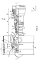
- a gas turbine engine 20 is provided.
- the gas turbine engine 20 may be a two-spool turbofan that generally incorporates a fan section 22, a compressor section 24, a combustor section 26 and a turbine section 28.
- Alternative engines may include, for example, an augmentor section among other systems or features.
- the fan section 22 can drive coolant (e.g., air) along a bypass flow path B while the compressor section 24 can drive coolant along a core flow path C for compression and communication into the combustor section 26 then expansion through the turbine section 28.
- turbofan gas turbine engine 20 Although depicted as a two-spool turbofan gas turbine engine 20 herein, it should be understood that the concepts described herein are not limited to use with two-spool turbofans as the teachings may be applied to other types of turbine engines including turbojet, turboprop, turboshaft, or power generation turbines, with or without geared fan, geared compressor or three-spool architectures.
- the gas turbine engine 20 may generally comprise a low speed spool 30 and a high speed spool 32 mounted for rotation about an engine central longitudinal axis X-X' relative to an engine static structure 36 or engine case via several bearing systems 38, 38-1, and 38-2. It should be understood that various bearing systems 38 at various locations may alternatively or additionally be provided, including for example, the bearing system 38, the bearing system 38-1, and the bearing system 38-2.
- the low speed spool 30 may generally comprise an inner shaft 40 that interconnects a fan 42, a low pressure compressor 44 and a low pressure turbine 46.
- the inner shaft 40 may be connected to the fan 42 through a geared architecture 48 that can drive the fan 42 at a lower speed than the low speed spool 30.
- the geared architecture 48 may comprise a gear assembly 60 enclosed within a gear housing 62.
- the gear assembly 60 couples the inner shaft 40 to a rotating fan structure.
- the high speed spool 32 may comprise an outer shaft 50 that interconnects a high pressure compressor 52 and high pressure turbine 54.
- a combustor 26 may be located between high pressure compressor 52 and high pressure turbine 54.
- a mid-turbine frame 57 of the engine static structure 36 may be located generally between the high pressure turbine 54 and the low pressure turbine 46.
- Mid-turbine frame 57 may support one or more bearing systems 38 in the turbine section 28.
- the inner shaft 40 and the outer shaft 50 may be concentric and rotate via bearing systems 38 about the engine central longitudinal axis X-X', which is collinear with their longitudinal axes.
- a "high pressure" compressor or turbine experiences a higher pressure than a corresponding "low pressure” compressor or turbine.
- gas turbine 20 may include, for example, stator vane assembly 200 depicted in FIG. 2 .
- Stator vane assembly 200 may include, for example, an outer diameter shroud 240, an inner diameter shroud 202, vanes 204, bolts 212, and wedge clips 206.
- Outer diameter shroud 240 may include a plurality of outer diameter slots 230.
- Inner diameter shroud 202 may include a plurality of inner diameter slots 220.
- inner diameter shroud 202 and outer diameter shroud 210 may be radially spaced apart such that vanes 204 may be arranged circumferentially about the X axis depicted in FIG. 1 .
- Vanes 204 may be arranged to support stator vane assembly 200 and may be positioned to extend from inner diameter shroud 202 to outer diameter shroud 240.
- vane 204 may have a first end 214 and a second end 215.
- First end 214 may have a slot 224 associated with first end 214.
- Second end 215 may have a slot 226 (shown in FIG. 5 ) associated with second end 215.
- First end 214 of vane 204 extends through outer diameter shroud 240 via outer diameter slot 230, thereby allowing wedge clip 206 to be inserted into slot 224 to hold vane 204 firmly into place. The insertion of wedge clip 206 into slot 224 may tend to prevent vane 204 from being dislodged from stator vane assembly 200.
- outer diameter shroud 240 may be located radially outward from a plurality of vanes 204 and may retain the plurality of vanes 204 in place relative to stator vane assembly 200.
- Outer diameter shroud 240 may be coupled to, for example, a front center body (FCB) with bolts 212.
- bolts 212 may be used to bolt outer diameter shroud to the FCB for bird strike resistance.
- the addition of a single piece outer diameter shroud 240 allows for vanes 204 to remain secure, preventing vanes 204 from undesirably becoming dislodged in response to sufficient radially outward deflection of the outer diameter shroud 240.
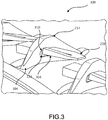
- FIG. 3 depicts a perspective view of a portion 300 of stator vane assembly 200 according to various embodiments.
- FIG. 3 shows a structural example of wedge clip 206 preventing vane 204 from being dislodged from stator assembly 200.
- Vane 204 includes first end 214, slot 224, and a slot edge 310.
- Wedge clip 206 includes a wedge portion 304 (e.g., a tine, locking arm, or locking tab) cut from the side of wedge clip 206.
- wedge clip 206 may be inserted horizontally into slot 224 to allow vane 204 to remain securely fastened to outer diameter shroud 240.
- Wedge portion 304 extends radially such that wedge clip 206 is able to prevent wedge clip 206 from being dislodged.
- wedge portion 304 may be bent radially to prevent wedge clip 206 from backing out slot 224. Wedge portion 304 may, for example, bend and/or displace vertically during installation and spring back into place once wedge portion 304 extends through slot 224.
- wedge portion 304 may be designed such that the thickness of wedge portion 304 combined with the angle of elevation of wedge portion 304 prevents wedge clip 206 from being dislodged.
- the wedge shape of wedge clip 206 may prevent the wedge portion 304 from pushing through slot 224 and hold wedge clip 206 in place to prevent circumferential migration due to vibration..
- FIG. 4 illustrates a top view perspective of wedge clip 206 of stator vane assembly 200 according to various embodiments.
- Wedge clip 206 includes a first side portion 408, a first side portion 418, a second side portion 410, a third side portion 428, a fourth side portion 414, a fifth side portion 404, a sixth side portion 440, a seventh side portion 430, a second side 422, and a first side 450.
- Wedge portion 304 of wedge clip 206 includes a first end 444, a second end 446, first side 450, second side 422, a third side 421, and a bendable edge 431.
- first side portion 408 is coupled to fourth side portion 414 at point A.
- Fourth side portion 414 is coupled to second side portion 410 point B.
- Second side portion 410 is coupled to third side portion 428 point C.
- Third side portion 428 is coupled to fifth side portion 404 at point D.
- Fifth side portion 404 is coupled to first side portion 418 at point E.
- First side portion 418 is coupled to first side 450 at point F.
- First side 450 is coupled to second side 422 at point G.
- Second side 422 is coupled to seventh side 430 at point H.
- Seventh side 430 is coupled to sixth side portion 440 at point I.
- Sixth side portion 440 is coupled to first side portion 408 at point J.
- points A, B, E, F, G, I, and J are cornered points whose coupled sides corner to approximately 90 degrees.
- Points C and D are quasi-corned points whose coupled sides have angles equating to greater than 90 degrees.
- point H has incoming sides that form a U-shape at point H.
- wedge portion 304 is bendable or flexible at bendable edge 431.
- wedge portion 304 has a thickness at first end 444 of wedge portion 304 that increases in the direction of slot 224 toward vane 204. In various embodiments, the thickness of is greater than the thickness at a second end 446 of wedge portion 304.
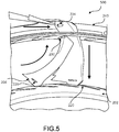
- FIG. 5 illustrates a method 500 of installing vane 204 into stator vane assembly 200 according to various embodiments.
- vane 204 is angled or rocked into outer diameter shroud 240. Vane 204 is pushed or placed into inner diameter shroud 202.
- Wedge clip 206 (depicted in FIG. 2 ) is placed into slot 224.
- wedge portion 304 (depicted in FIG. 3 ) of wedge clip 206 bends flush as wedge clip 206 is pushed through slot 224.
- Wedge portion 304 may bend radially relative to the engine central longitudinal axis X-X' so that wedge clip 206 clips in place to vane 204, thereby minimizing the dislodging of vane 204 from stator vane assembly 200.
- wedge portion 304 may spring back into its initial position once wedge portion 304 passes through slot 224.
- wedge portion 304 acts as a mechanical retention mechanism.
- the shape of wedge clip 206 centers wedge clip 206 (i.e., allows wedge clip 206 to self-center itself in slot 224) with respect to vane 204 thereby preventing the toggling of wedge clip 206 radially, axially, and/or circumferentially relative to the engine central longitudinal axis X-X'.
- the outer diameter shroud 240 may be a single piece. As described, it is desirable for the outer diameter shroud 240 to resist movement in the radially outward direction which may occur, for example, during a bird strike (i.e., when a bird is ingested into gas turbine engine 20).
- references to "one embodiment”, “an embodiment”, “an example embodiment”, etc. indicate that the embodiment described may include a particular feature, structure, or characteristic, but every embodiment may not necessarily include the particular feature, structure, or characteristic. Moreover, such phrases are not necessarily referring to the same embodiment. Further, when a particular feature, structure, or characteristic is described in connection with an embodiment, it is submitted that it is within the knowledge of one skilled in the art to affect such feature, structure, or characteristic in connection with other embodiments whether or not explicitly described. After reading the description, it will be apparent to one skilled in the relevant art(s) how to implement the disclosure in alternative embodiments.
Landscapes
- Engineering & Computer Science (AREA)
- Mechanical Engineering (AREA)
- General Engineering & Computer Science (AREA)
- Turbine Rotor Nozzle Sealing (AREA)
Abstract
Description
- The present disclosure is directed to a gas turbine engine. More particularly, to a stator vane assembly and a method of installing a stator vane in a gas turbine engine.
- Gas turbine engines include a compressor section, a turbine section, and a combustor section. Many gas turbine engines also include a fan that is driven by the turbine section. The fan generates a core airflow that is received by the compressor section and a bypass airflow that bypasses the compressor, turbine, and combustor sections and generates thrust. Stator vanes may be located upstream from the compressor and may condition the core airflow. It is undesirable for the stator vanes to become dislodged in response to ingestion of an object, such as a bird, in the core airflow.
- In various embodiments, a gas turbine engine having a stator vane assembly includes an inner diameter shroud, an outer diameter shroud located radially outward from the inner diameter shroud, and a vane extending radially outward from the first inner diameter shroud to the outer diameter shroud. A wedge clip is positioned horizontally through the vane to prevent the vane from being dislodged from the stator vane assembly. In various embodiments, the vane of gas turbine engine has a first end and a first slot located at the first end, the first slot being used to position the wedge clip.
- The wedge clip of the gas turbine engine has a wedge portion that prevents the wedge portion from dislodging from the stator vane assembly. In various embodiments, the outer diameter shroud of the gas turbine engine is a single unit outer diameter shroud. The wedge clip of the gas turbine engine has a wedge portion with a first end having a first thickness and a bendable edge having a second thickness, wherein the first thickness is greater than the second thickness. The wedge portion of the wedge clip of the gas turbine engine springs to an initial position after being placed through a first slot at a first end of the vane. In various embodiments, a width of a wedge portion of the wedge clip and an angle of elevation of a first side of the wedge portion prevents the wedge clip and the vane from being dislodged. In various embodiments, a bendable edge of the wedge clip of the gas turbine engine allows the wedge clip to prevent the vane from dislodging from the outer diameter shroud.
- In various embodiments of the gas turbine engine, a u-shape coupling of a wedge portion of the wedge clip to a non-wedge portion of the wedge clip allows the wedge portion to be a bendable wedge portion. In various embodiments of the gas turbine engine, a cornered and a quasi-corned design of the wedge clip self-centers the wedge clip to prevent a toggling of the wedge clip in a horizontal or a vertical direction.
- In various embodiments, a method of assembling a stator vane assembly includes angling a vane into a first slot of an outer diameter shroud, aligning the vane into a first slot of an inner diameter shroud, and placing a wedge clip into a first slot of the vane to prevent the vane from dislodging from the stator vane assembly. In various embodiments, the method further includes bending a wedge portion of the wedge clip flush with the wedge clip when placing the wedge clip into the first slot of the vane. In various embodiments, the method further includes self-centering the wedge clip into the first slot of the vane when placing the wedge clip into the first slot of the vane. In various embodiments, the method further includes using a wedge portion of the wedge clip to act as a mechanical retention mechanism of the wedge clip to the stator vane assembly.
- In various embodiments, a stator vane assembly includes an inner diameter shroud, an outer diameter shroud located radially outward from the inner diameter shroud, and a vane extending radially outward from the first inner diameter shroud to the outer diameter shroud, wherein a wedge clip is positioned horizontally through the vane to prevent the vane from being dislodged from the stator vane assembly. In various embodiments of the stator vane assembly, the vane has a first end and a first slot located at the first end, the first slot being used to position the wedge clip. In various embodiments of the stator vane assembly, the wedge clip has a wedge portion that prevents the wedge clip from dislodging from the stator vane assembly. In various embodiments of the stator vane assembly, the outer diameter shroud is a single unit outer diameter shroud.
- In various embodiments of the stator vane assembly, a u-shape coupling of a wedge portion of the wedge clip to a non-wedge portion of the wedge clip allows the wedge portion to be a bendable wedge portion.
- The foregoing features and elements may be combined in various combinations without exclusivity, unless expressly indicated otherwise. These features and elements as well as the operation thereof will become more apparent in light of the following description and the accompanying drawings. It should be understood, however, the following description and drawings are intended to be exemplary in nature and non-limiting.
- Various features will become apparent to those skilled in the art from the following detailed description of the disclosed, non-limiting, embodiments. The drawings that accompany the detailed description can be briefly described as follows:
-
FIG. 1 is a cross-sectional view of an exemplary gas turbine engine, in accordance with various embodiments; -
FIG. 2 is a perspective view of a portion of a stator vane assembly, in accordance with various embodiments; -
FIG. 3 is a perspective view of a portion of a stator vane assembly, in accordance with various embodiments; -
FIG. 4 is a top view perspective of the wedge clip of the stator vane assembly ofFIG. 3 , in accordance with various embodiments; and -
FIG. 5 is an illustration of methods of installing a vane and wedge clip into a stator vane assembly of a gas turbine engine, in accordance with various embodiments. - All ranges and ratio limits disclosed herein may be combined. It is to be understood that unless specifically stated otherwise, references to "a," "an," and/or "the" may include one or more than one and that reference to an item in the singular may also include the item in the plural.
- The detailed description of various embodiments herein makes reference to the accompanying drawings, which show various embodiments by way of illustration. While these various embodiments are described in sufficient detail to enable those skilled in the art to practice the disclosure, it should be understood that other embodiments may be realized and that logical, chemical, and mechanical changes may be made without departing from the scope of the disclosure. Thus, the detailed description herein is presented for purposes of illustration only and not of limitation. For example, the steps recited in any of the method or process descriptions may be executed in any order and are not necessarily limited to the order presented. Furthermore, any reference to singular includes plural embodiments, and any reference to more than one component or step may include a singular embodiment or step. Also, any reference to attached, fixed, connected, or the like may include permanent, removable, temporary, partial, full, and/or any other possible attachment option. Additionally, any reference to without contact (or similar phrases) may also include reduced contact or minimal contact. Cross hatching lines may be used throughout the figures to denote different parts but not necessarily to denote the same or different materials.
- As used herein, "aft" refers to the direction associated with the exhaust (e.g., the back end) of a gas turbine engine. As used herein, "forward" refers to the direction associated with the intake (e.g., the front end) of a gas turbine engine. An A-R-C axis is shown in various drawings to illustrate the axial, radial, and circumferential directions, respectively.
- As used herein, "radially outward" refers to the direction generally away from the axis of rotation of a turbine engine. As used herein, "radially inward" refers to the direction generally towards the axis of rotation of a turbine engine.
- In various embodiments and with reference to
FIG. 1 , agas turbine engine 20 is provided. Thegas turbine engine 20 may be a two-spool turbofan that generally incorporates afan section 22, acompressor section 24, acombustor section 26 and aturbine section 28. Alternative engines may include, for example, an augmentor section among other systems or features. In operation, thefan section 22 can drive coolant (e.g., air) along a bypass flow path B while thecompressor section 24 can drive coolant along a core flow path C for compression and communication into thecombustor section 26 then expansion through theturbine section 28. Although depicted as a two-spool turbofangas turbine engine 20 herein, it should be understood that the concepts described herein are not limited to use with two-spool turbofans as the teachings may be applied to other types of turbine engines including turbojet, turboprop, turboshaft, or power generation turbines, with or without geared fan, geared compressor or three-spool architectures. - The
gas turbine engine 20 may generally comprise alow speed spool 30 and ahigh speed spool 32 mounted for rotation about an engine central longitudinal axis X-X' relative to an enginestatic structure 36 or engine case viaseveral bearing systems 38, 38-1, and 38-2. It should be understood thatvarious bearing systems 38 at various locations may alternatively or additionally be provided, including for example, thebearing system 38, the bearing system 38-1, and the bearing system 38-2. - The
low speed spool 30 may generally comprise aninner shaft 40 that interconnects afan 42, alow pressure compressor 44 and alow pressure turbine 46. Theinner shaft 40 may be connected to thefan 42 through a gearedarchitecture 48 that can drive thefan 42 at a lower speed than thelow speed spool 30. The gearedarchitecture 48 may comprise agear assembly 60 enclosed within a gear housing 62. Thegear assembly 60 couples theinner shaft 40 to a rotating fan structure. Thehigh speed spool 32 may comprise anouter shaft 50 that interconnects ahigh pressure compressor 52 andhigh pressure turbine 54. Acombustor 26 may be located betweenhigh pressure compressor 52 andhigh pressure turbine 54. Amid-turbine frame 57 of the enginestatic structure 36 may be located generally between thehigh pressure turbine 54 and thelow pressure turbine 46.Mid-turbine frame 57 may support one ormore bearing systems 38 in theturbine section 28. Theinner shaft 40 and theouter shaft 50 may be concentric and rotate via bearingsystems 38 about the engine central longitudinal axis X-X', which is collinear with their longitudinal axes. As used herein, a "high pressure" compressor or turbine experiences a higher pressure than a corresponding "low pressure" compressor or turbine. - In various embodiments,
gas turbine 20 may include, for example,stator vane assembly 200 depicted inFIG. 2 .Stator vane assembly 200 may include, for example, anouter diameter shroud 240, aninner diameter shroud 202,vanes 204,bolts 212, and wedge clips 206.Outer diameter shroud 240 may include a plurality ofouter diameter slots 230.Inner diameter shroud 202 may include a plurality ofinner diameter slots 220. In various embodiments,inner diameter shroud 202 and outer diameter shroud 210 may be radially spaced apart such thatvanes 204 may be arranged circumferentially about the X axis depicted inFIG. 1 .Vanes 204 may be arranged to supportstator vane assembly 200 and may be positioned to extend frominner diameter shroud 202 toouter diameter shroud 240. - In various embodiments,
vane 204 may have afirst end 214 and asecond end 215.First end 214 may have aslot 224 associated withfirst end 214.Second end 215 may have a slot 226 (shown inFIG. 5 ) associated withsecond end 215.First end 214 ofvane 204 extends throughouter diameter shroud 240 viaouter diameter slot 230, thereby allowingwedge clip 206 to be inserted intoslot 224 to holdvane 204 firmly into place. The insertion ofwedge clip 206 intoslot 224 may tend to preventvane 204 from being dislodged fromstator vane assembly 200. - In various embodiments,
outer diameter shroud 240 may be located radially outward from a plurality ofvanes 204 and may retain the plurality ofvanes 204 in place relative tostator vane assembly 200.Outer diameter shroud 240 may be coupled to, for example, a front center body (FCB) withbolts 212. In various embodiments,bolts 212 may be used to bolt outer diameter shroud to the FCB for bird strike resistance. In various embodiments, the addition of a single pieceouter diameter shroud 240 allows forvanes 204 to remain secure, preventingvanes 204 from undesirably becoming dislodged in response to sufficient radially outward deflection of theouter diameter shroud 240. In various embodiments, it may desirable to reduce radially outward deflection ofouter diameter shroud 240. -
FIG. 3 depicts a perspective view of aportion 300 ofstator vane assembly 200 according to various embodiments. In various embodiments,FIG. 3 shows a structural example ofwedge clip 206 preventingvane 204 from being dislodged fromstator assembly 200.Vane 204 includesfirst end 214,slot 224, and aslot edge 310.Wedge clip 206 includes a wedge portion 304 (e.g., a tine, locking arm, or locking tab) cut from the side ofwedge clip 206. In various embodiments,wedge clip 206 may be inserted horizontally intoslot 224 to allowvane 204 to remain securely fastened toouter diameter shroud 240.Wedge portion 304 extends radially such thatwedge clip 206 is able to preventwedge clip 206 from being dislodged. In various embodiments,wedge portion 304 may be bent radially to preventwedge clip 206 from backing outslot 224.Wedge portion 304 may, for example, bend and/or displace vertically during installation and spring back into place oncewedge portion 304 extends throughslot 224. In various embodiments,wedge portion 304 may be designed such that the thickness ofwedge portion 304 combined with the angle of elevation ofwedge portion 304 preventswedge clip 206 from being dislodged. In various embodiments, the wedge shape ofwedge clip 206 may prevent thewedge portion 304 from pushing throughslot 224 and holdwedge clip 206 in place to prevent circumferential migration due to vibration.. -
FIG. 4 illustrates a top view perspective ofwedge clip 206 ofstator vane assembly 200 according to various embodiments.Wedge clip 206 includes afirst side portion 408, afirst side portion 418, asecond side portion 410, athird side portion 428, afourth side portion 414, afifth side portion 404, asixth side portion 440, aseventh side portion 430, asecond side 422, and afirst side 450.Wedge portion 304 ofwedge clip 206 includes afirst end 444, asecond end 446,first side 450,second side 422, athird side 421, and abendable edge 431. - In various embodiments,
first side portion 408 is coupled tofourth side portion 414 at point A.Fourth side portion 414 is coupled tosecond side portion 410 point B.Second side portion 410 is coupled tothird side portion 428 point C.Third side portion 428 is coupled tofifth side portion 404 at point D.Fifth side portion 404 is coupled tofirst side portion 418 at point E.First side portion 418 is coupled tofirst side 450 at point F.First side 450 is coupled tosecond side 422 at pointG. Second side 422 is coupled toseventh side 430 at pointH. Seventh side 430 is coupled tosixth side portion 440 at point I.Sixth side portion 440 is coupled tofirst side portion 408 at point J. In various embodiments, points A, B, E, F, G, I, and J are cornered points whose coupled sides corner to approximately 90 degrees. Points C and D are quasi-corned points whose coupled sides have angles equating to greater than 90 degrees. In various embodiments, point H has incoming sides that form a U-shape at point H. In various embodiments,wedge portion 304 is bendable or flexible atbendable edge 431. In various embodiments,wedge portion 304 has a thickness atfirst end 444 ofwedge portion 304 that increases in the direction ofslot 224 towardvane 204. In various embodiments, the thickness of is greater than the thickness at asecond end 446 ofwedge portion 304. -
FIG. 5 illustrates amethod 500 of installingvane 204 intostator vane assembly 200 according to various embodiments. In various embodiments,vane 204 is angled or rocked intoouter diameter shroud 240.Vane 204 is pushed or placed intoinner diameter shroud 202. Wedge clip 206 (depicted inFIG. 2 ) is placed intoslot 224. In various embodiments, wedge portion 304 (depicted inFIG. 3 ) ofwedge clip 206 bends flush aswedge clip 206 is pushed throughslot 224.Wedge portion 304 may bend radially relative to the engine central longitudinal axis X-X' so thatwedge clip 206 clips in place to vane 204, thereby minimizing the dislodging ofvane 204 fromstator vane assembly 200. In various embodiments,wedge portion 304 may spring back into its initial position oncewedge portion 304 passes throughslot 224. In various embodiments,wedge portion 304 acts as a mechanical retention mechanism. In various embodiments, the shape ofwedge clip 206 centers wedge clip 206 (i.e., allowswedge clip 206 to self-center itself in slot 224) with respect tovane 204 thereby preventing the toggling ofwedge clip 206 radially, axially, and/or circumferentially relative to the engine central longitudinal axis X-X'. - In various embodiments, the
outer diameter shroud 240 may be a single piece. As described, it is desirable for theouter diameter shroud 240 to resist movement in the radially outward direction which may occur, for example, during a bird strike (i.e., when a bird is ingested into gas turbine engine 20). - While the disclosure is described with reference to exemplary embodiments, it will be understood by those skilled in the art that various changes may be made and equivalents may be substituted without departing from the scope of the disclosure. In addition, different modifications may be made to adapt the teachings of the disclosure to particular situations or materials, without departing from the scope thereof. The disclosure is thus not limited to the particular examples disclosed herein, but includes all embodiments falling within the scope of the appended claims.
- Benefits, other advantages, and solutions to problems have been described herein with regard to specific embodiments. Furthermore, the connecting lines shown in the various figures contained herein are intended to represent exemplary functional relationships and/or physical couplings between the various elements. It should be noted that many alternative or additional functional relationships or physical connections may be present in a practical system. However, the benefits, advantages, solutions to problems, and any elements that may cause any benefit, advantage, or solution to occur or become more pronounced are not to be construed as critical, required, or essential features or elements of the disclosure. The scope of the disclosure is accordingly to be limited by nothing other than the appended claims, in which reference to an element in the singular is not intended to mean "one and only one" unless explicitly so stated, but rather "one or more." Moreover, where a phrase similar to "at least one of a, b, or c" is used in the claims, it is intended that the phrase be interpreted to mean that a alone may be present in an embodiment, b alone may be present in an embodiment, c alone may be present in an embodiment, or that any combination of the elements a, b and c may be present in a single embodiment; for example, a and b, a and c, b and c, or a and b and c. Different cross-hatching is used throughout the figures to denote different parts but not necessarily to denote the same or different materials.
- Systems, methods and apparatus are provided herein. In the detailed description herein, references to "one embodiment", "an embodiment", "an example embodiment", etc., indicate that the embodiment described may include a particular feature, structure, or characteristic, but every embodiment may not necessarily include the particular feature, structure, or characteristic. Moreover, such phrases are not necessarily referring to the same embodiment. Further, when a particular feature, structure, or characteristic is described in connection with an embodiment, it is submitted that it is within the knowledge of one skilled in the art to affect such feature, structure, or characteristic in connection with other embodiments whether or not explicitly described. After reading the description, it will be apparent to one skilled in the relevant art(s) how to implement the disclosure in alternative embodiments.
- Furthermore, no element, component, or method step in the present disclosure is intended to be dedicated to the public regardless of whether the element, component, or method step is explicitly recited in the claims. No claim element herein is to be construed under the provisions of 35 U.S.C. 112(f), unless the element is expressly recited using the phrase "means for." As used herein, the terms "comprises", "comprising", or any other variation thereof, are intended to cover a non-exclusive inclusion, such that a process, method, article, or apparatus that comprises a list of elements does not include only those elements but may include other elements not expressly listed or inherent to such process, method, article, or apparatus.
Claims (15)
- A gas turbine engine having a stator vane assembly comprising:an inner diameter shroud;an outer diameter shroud located radially outward from said inner diameter shroud; anda vane extending radially outward from said inner diameter shroud to said outer diameter shroud, wherein a wedge clip is positioned axially through said vane to prevent said vane from being dislodged from said stator vane assembly.
- The gas turbine engine of claim 1, wherein said outer diameter shroud is a unitary continuous material.
- The gas turbine engine of claim 1 or 2, wherein said wedge clip has a wedge portion with a first end having a first thickness and a bendable edge able to be flexed radially and having a second thickness, wherein said first thickness is greater that said second thickness.
- The gas turbine engine of claim 1, 2 or 3, wherein a wedge portion of said wedge clip springs to an initial position after being placed through a first slot at a first end of said vane.
- The gas turbine engine of any preceding claim, wherein a width of a wedge portion of said wedge clip and an angle of elevation of a first side of said wedge portion prevents said wedge clip and said vane from being dislodged.
- The gas turbine engine of any preceding claim, wherein a bendable edge of said wedge clip allows said wedge clip to prevent said vane from dislodging from said outer diameter shroud.
- The gas turbine engine of any preceding claim, wherein a cornered and a quasi-corned design of said wedge clip self-centers said wedge clip to prevent a toggling of said wedge clip radially, axially, and/or circumferentially relative to an engine central longitudinal axis X-X'.
- A method of assembling a stator vane assembly comprising:angling a vane into a first slot of an outer diameter shroud;aligning said vane into a first slot of an inner diameter shroud; andplacing a wedge clip into a first slot of said vane to prevent said vane from dislodging from said stator vane assembly.
- The method of claim 8 further comprising bending a wedge portion of said wedge clip flush with said wedge clip when placing said wedge clip into said first slot of said vane, and/or
optionally further comprising extending said vane from said inner diameter shroud to said outer diameter shroud, and/or
optionally further comprising self-centering said wedge clip into said first slot of said vane when placing said wedge clip into said first slot of said vane. - The method of claim 8 or 9 further comprising using a wedge portion of said wedge clip to act as a mechanical retention mechanism of said wedge clip to said stator vane assembly.
- A stator vane assembly comprising:an inner diameter shroud;an outer diameter shroud located radially outward from said inner diameter shroud; anda vane extending radially outward from said inner diameter shroud to said outer diameter shroud, wherein a wedge clip is positioned axially through said vane to prevent said vane from being dislodged from said stator vane assembly.
- The gas turbine engine of any of claims 1 to 7 or the stator vane assembly of claim 11, wherein said vane has a first end and a first slot located at said first end, said first slot being used to position said wedge clip.
- The gas turbine engine of any of claims 1 to 7 or 12 or the stator vane assembly of claim 11 or 12, wherein said wedge clip has a wedge portion that prevents said wedge clip from dislodging from said stator vane assembly.
- The stator vane assembly of claim 11, 12 or 13, wherein said outer diameter shroud is a single unit outer diameter shroud.
- The gas turbine engine of any of claims 1 to 7, 12 or 13 or the stator vane assembly of any of claims 11 to 14, wherein a u-shape coupling of a wedge portion of said wedge clip to a non-wedge portion of said wedge clip allows said wedge portion to be a bendable wedge portion.
Applications Claiming Priority (1)
| Application Number | Priority Date | Filing Date | Title |
|---|---|---|---|
| US15/645,881 US10724389B2 (en) | 2017-07-10 | 2017-07-10 | Stator vane assembly for a gas turbine engine |
Publications (2)
| Publication Number | Publication Date |
|---|---|
| EP3428403A1 true EP3428403A1 (en) | 2019-01-16 |
| EP3428403B1 EP3428403B1 (en) | 2021-08-04 |
Family
ID=62778791
Family Applications (1)
| Application Number | Title | Priority Date | Filing Date |
|---|---|---|---|
| EP18179562.6A Active EP3428403B1 (en) | 2017-07-10 | 2018-06-25 | Stator vane assembly for a gas turbine engine and method of assembling the same |
Country Status (2)
| Country | Link |
|---|---|
| US (1) | US10724389B2 (en) |
| EP (1) | EP3428403B1 (en) |
Families Citing this family (4)
| Publication number | Priority date | Publication date | Assignee | Title |
|---|---|---|---|---|
| US10655502B2 (en) * | 2017-05-26 | 2020-05-19 | United Technologies Corporation | Stator assembly with retention clip for gas turbine engine |
| US20190234222A1 (en) * | 2018-01-30 | 2019-08-01 | United Technologies Corporation | Angled vane slot |
| CN111734499B (en) * | 2020-04-21 | 2022-08-19 | 中国航发沈阳发动机研究所 | Booster stage stator blade limiting block and booster stage stator part with same |
| FR3137714B1 (en) * | 2022-07-07 | 2025-05-30 | Safran Aircraft Engines | Inlet casing of a turbomachine |
Citations (6)
| Publication number | Priority date | Publication date | Assignee | Title |
|---|---|---|---|---|
| US2812159A (en) * | 1952-08-19 | 1957-11-05 | Gen Electric | Securing means for turbo-machine blading |
| GB2272027A (en) * | 1992-10-28 | 1994-05-04 | Snecma | Interlocking the ends of blades |
| EP1079075A2 (en) * | 1999-08-09 | 2001-02-28 | United Technologies Corporation | Stator assembly for a rotary machine and clip member for a stator assembly |
| EP2072760A1 (en) * | 2007-12-21 | 2009-06-24 | Techspace aero | Device for attaching vanes to a stage collar of a turbomachine stator and associated attachment method |
| EP2204539A2 (en) * | 2008-12-31 | 2010-07-07 | General Electric Company | Stator assembly for a gas turbine engine |
| WO2015132523A2 (en) * | 2014-03-06 | 2015-09-11 | Herakles | Stator section for a turbomachine and method for producing the same |
Family Cites Families (6)
| Publication number | Priority date | Publication date | Assignee | Title |
|---|---|---|---|---|
| US4452564A (en) | 1981-11-09 | 1984-06-05 | The Garrett Corporation | Stator vane assembly and associated methods |
| DE60026686T2 (en) * | 2000-12-06 | 2006-10-05 | Techspace Aero S.A. | Stator stage of a compressor |
| FR2930592B1 (en) * | 2008-04-24 | 2010-04-30 | Snecma | TURBINE DISPENSER FOR A TURBOMACHINE |
| US8910947B2 (en) | 2010-03-30 | 2014-12-16 | United Technologies Corporation | Method of forming a seal element |
| FR2971022B1 (en) * | 2011-02-02 | 2013-01-04 | Snecma | COMPRESSOR RECTIFIER STAGE FOR A TURBOMACHINE |
| US10465541B2 (en) * | 2013-03-15 | 2019-11-05 | United Technologies Corporation | Gas turbine engine stator vane assembly with split shroud |
-
2017
- 2017-07-10 US US15/645,881 patent/US10724389B2/en active Active
-
2018
- 2018-06-25 EP EP18179562.6A patent/EP3428403B1/en active Active
Patent Citations (6)
| Publication number | Priority date | Publication date | Assignee | Title |
|---|---|---|---|---|
| US2812159A (en) * | 1952-08-19 | 1957-11-05 | Gen Electric | Securing means for turbo-machine blading |
| GB2272027A (en) * | 1992-10-28 | 1994-05-04 | Snecma | Interlocking the ends of blades |
| EP1079075A2 (en) * | 1999-08-09 | 2001-02-28 | United Technologies Corporation | Stator assembly for a rotary machine and clip member for a stator assembly |
| EP2072760A1 (en) * | 2007-12-21 | 2009-06-24 | Techspace aero | Device for attaching vanes to a stage collar of a turbomachine stator and associated attachment method |
| EP2204539A2 (en) * | 2008-12-31 | 2010-07-07 | General Electric Company | Stator assembly for a gas turbine engine |
| WO2015132523A2 (en) * | 2014-03-06 | 2015-09-11 | Herakles | Stator section for a turbomachine and method for producing the same |
Also Published As
| Publication number | Publication date |
|---|---|
| US20190010816A1 (en) | 2019-01-10 |
| EP3428403B1 (en) | 2021-08-04 |
| US10724389B2 (en) | 2020-07-28 |
Similar Documents
| Publication | Publication Date | Title |
|---|---|---|
| EP3428403A1 (en) | Stator vane assembly for a gas turbine engine and method of assembling the same | |
| CN104081007B (en) | A support component of turbine gear drive framework | |
| EP3306056A1 (en) | Flange heat shield | |
| US11428241B2 (en) | System for an improved stator assembly | |
| EP3508700B1 (en) | Boas having radially extended protrusions | |
| EP3477047B1 (en) | Segmented structural links for coupled disk frequency tuning and corresponding gas turbine engine with such links | |
| US10393024B2 (en) | Multi-air stream cooling system | |
| US11008886B2 (en) | Variable vane stabilizer | |
| EP3409904B1 (en) | Systems for reducing deflection of a shroud that retains fan exit stators | |
| EP3569818B1 (en) | Support ring with thermal heat shield for case flanges | |
| EP3722633A1 (en) | Vibration isolator assembly | |
| EP3453835B1 (en) | Fan exit stator assembly | |
| US11215083B2 (en) | Retention hardware | |
| EP3296515A2 (en) | Anti-rotation stator vane assembly | |
| EP3054115A1 (en) | Method for limiting movement of a retaining ring and retaining ring assembly | |
| US11215084B2 (en) | Support straps and method of assembly for gas turbine engine | |
| EP3054092B1 (en) | Cooling structure with swirler tube and method of assembly | |
| US9897210B2 (en) | Knife edge seal tree | |
| EP3412873A1 (en) | Stator assembly with retention clip for gas turbine engine | |
| US20210123355A1 (en) | System for an improved stator assembly | |
| EP3214277A1 (en) | Systems for stiffening cases on gas-turbine engines |
Legal Events
| Date | Code | Title | Description |
|---|---|---|---|
| PUAI | Public reference made under article 153(3) epc to a published international application that has entered the european phase |
Free format text: ORIGINAL CODE: 0009012 |
|
| STAA | Information on the status of an ep patent application or granted ep patent |
Free format text: STATUS: THE APPLICATION HAS BEEN PUBLISHED |
|
| AK | Designated contracting states |
Kind code of ref document: A1 Designated state(s): AL AT BE BG CH CY CZ DE DK EE ES FI FR GB GR HR HU IE IS IT LI LT LU LV MC MK MT NL NO PL PT RO RS SE SI SK SM TR |
|
| AX | Request for extension of the european patent |
Extension state: BA ME |
|
| STAA | Information on the status of an ep patent application or granted ep patent |
Free format text: STATUS: REQUEST FOR EXAMINATION WAS MADE |
|
| 17P | Request for examination filed |
Effective date: 20190716 |
|
| RBV | Designated contracting states (corrected) |
Designated state(s): AL AT BE BG CH CY CZ DE DK EE ES FI FR GB GR HR HU IE IS IT LI LT LU LV MC MK MT NL NO PL PT RO RS SE SI SK SM TR |
|
| STAA | Information on the status of an ep patent application or granted ep patent |
Free format text: STATUS: EXAMINATION IS IN PROGRESS |
|
| 17Q | First examination report despatched |
Effective date: 20191203 |
|
| GRAP | Despatch of communication of intention to grant a patent |
Free format text: ORIGINAL CODE: EPIDOSNIGR1 |
|
| STAA | Information on the status of an ep patent application or granted ep patent |
Free format text: STATUS: GRANT OF PATENT IS INTENDED |
|
| INTG | Intention to grant announced |
Effective date: 20201006 |
|
| GRAJ | Information related to disapproval of communication of intention to grant by the applicant or resumption of examination proceedings by the epo deleted |
Free format text: ORIGINAL CODE: EPIDOSDIGR1 |
|
| STAA | Information on the status of an ep patent application or granted ep patent |
Free format text: STATUS: EXAMINATION IS IN PROGRESS |
|
| INTC | Intention to grant announced (deleted) | ||
| GRAP | Despatch of communication of intention to grant a patent |
Free format text: ORIGINAL CODE: EPIDOSNIGR1 |
|
| STAA | Information on the status of an ep patent application or granted ep patent |
Free format text: STATUS: GRANT OF PATENT IS INTENDED |
|
| INTG | Intention to grant announced |
Effective date: 20210203 |
|
| RAP1 | Party data changed (applicant data changed or rights of an application transferred) |
Owner name: RAYTHEON TECHNOLOGIES CORPORATION |
|
| GRAS | Grant fee paid |
Free format text: ORIGINAL CODE: EPIDOSNIGR3 |
|
| GRAA | (expected) grant |
Free format text: ORIGINAL CODE: 0009210 |
|
| STAA | Information on the status of an ep patent application or granted ep patent |
Free format text: STATUS: THE PATENT HAS BEEN GRANTED |
|
| AK | Designated contracting states |
Kind code of ref document: B1 Designated state(s): AL AT BE BG CH CY CZ DE DK EE ES FI FR GB GR HR HU IE IS IT LI LT LU LV MC MK MT NL NO PL PT RO RS SE SI SK SM TR |
|
| REG | Reference to a national code |
Ref country code: GB Ref legal event code: FG4D |
|
| REG | Reference to a national code |
Ref country code: AT Ref legal event code: REF Ref document number: 1417182 Country of ref document: AT Kind code of ref document: T Effective date: 20210815 |
|
| REG | Reference to a national code |
Ref country code: CH Ref legal event code: EP |
|
| REG | Reference to a national code |
Ref country code: DE Ref legal event code: R096 Ref document number: 602018021080 Country of ref document: DE |
|
| REG | Reference to a national code |
Ref country code: IE Ref legal event code: FG4D |
|
| REG | Reference to a national code |
Ref country code: LT Ref legal event code: MG9D |
|
| REG | Reference to a national code |
Ref country code: NL Ref legal event code: MP Effective date: 20210804 |
|
| REG | Reference to a national code |
Ref country code: AT Ref legal event code: MK05 Ref document number: 1417182 Country of ref document: AT Kind code of ref document: T Effective date: 20210804 |
|
| PG25 | Lapsed in a contracting state [announced via postgrant information from national office to epo] |
Ref country code: RS Free format text: LAPSE BECAUSE OF FAILURE TO SUBMIT A TRANSLATION OF THE DESCRIPTION OR TO PAY THE FEE WITHIN THE PRESCRIBED TIME-LIMIT Effective date: 20210804 Ref country code: SE Free format text: LAPSE BECAUSE OF FAILURE TO SUBMIT A TRANSLATION OF THE DESCRIPTION OR TO PAY THE FEE WITHIN THE PRESCRIBED TIME-LIMIT Effective date: 20210804 Ref country code: HR Free format text: LAPSE BECAUSE OF FAILURE TO SUBMIT A TRANSLATION OF THE DESCRIPTION OR TO PAY THE FEE WITHIN THE PRESCRIBED TIME-LIMIT Effective date: 20210804 Ref country code: ES Free format text: LAPSE BECAUSE OF FAILURE TO SUBMIT A TRANSLATION OF THE DESCRIPTION OR TO PAY THE FEE WITHIN THE PRESCRIBED TIME-LIMIT Effective date: 20210804 Ref country code: FI Free format text: LAPSE BECAUSE OF FAILURE TO SUBMIT A TRANSLATION OF THE DESCRIPTION OR TO PAY THE FEE WITHIN THE PRESCRIBED TIME-LIMIT Effective date: 20210804 Ref country code: PT Free format text: LAPSE BECAUSE OF FAILURE TO SUBMIT A TRANSLATION OF THE DESCRIPTION OR TO PAY THE FEE WITHIN THE PRESCRIBED TIME-LIMIT Effective date: 20211206 Ref country code: NO Free format text: LAPSE BECAUSE OF FAILURE TO SUBMIT A TRANSLATION OF THE DESCRIPTION OR TO PAY THE FEE WITHIN THE PRESCRIBED TIME-LIMIT Effective date: 20211104 Ref country code: BG Free format text: LAPSE BECAUSE OF FAILURE TO SUBMIT A TRANSLATION OF THE DESCRIPTION OR TO PAY THE FEE WITHIN THE PRESCRIBED TIME-LIMIT Effective date: 20211104 Ref country code: AT Free format text: LAPSE BECAUSE OF FAILURE TO SUBMIT A TRANSLATION OF THE DESCRIPTION OR TO PAY THE FEE WITHIN THE PRESCRIBED TIME-LIMIT Effective date: 20210804 Ref country code: LT Free format text: LAPSE BECAUSE OF FAILURE TO SUBMIT A TRANSLATION OF THE DESCRIPTION OR TO PAY THE FEE WITHIN THE PRESCRIBED TIME-LIMIT Effective date: 20210804 |
|
| PG25 | Lapsed in a contracting state [announced via postgrant information from national office to epo] |
Ref country code: PL Free format text: LAPSE BECAUSE OF FAILURE TO SUBMIT A TRANSLATION OF THE DESCRIPTION OR TO PAY THE FEE WITHIN THE PRESCRIBED TIME-LIMIT Effective date: 20210804 Ref country code: LV Free format text: LAPSE BECAUSE OF FAILURE TO SUBMIT A TRANSLATION OF THE DESCRIPTION OR TO PAY THE FEE WITHIN THE PRESCRIBED TIME-LIMIT Effective date: 20210804 Ref country code: GR Free format text: LAPSE BECAUSE OF FAILURE TO SUBMIT A TRANSLATION OF THE DESCRIPTION OR TO PAY THE FEE WITHIN THE PRESCRIBED TIME-LIMIT Effective date: 20211105 |
|
| PG25 | Lapsed in a contracting state [announced via postgrant information from national office to epo] |
Ref country code: NL Free format text: LAPSE BECAUSE OF FAILURE TO SUBMIT A TRANSLATION OF THE DESCRIPTION OR TO PAY THE FEE WITHIN THE PRESCRIBED TIME-LIMIT Effective date: 20210804 |
|
| PG25 | Lapsed in a contracting state [announced via postgrant information from national office to epo] |
Ref country code: DK Free format text: LAPSE BECAUSE OF FAILURE TO SUBMIT A TRANSLATION OF THE DESCRIPTION OR TO PAY THE FEE WITHIN THE PRESCRIBED TIME-LIMIT Effective date: 20210804 |
|
| REG | Reference to a national code |
Ref country code: DE Ref legal event code: R097 Ref document number: 602018021080 Country of ref document: DE |
|
| PG25 | Lapsed in a contracting state [announced via postgrant information from national office to epo] |
Ref country code: SM Free format text: LAPSE BECAUSE OF FAILURE TO SUBMIT A TRANSLATION OF THE DESCRIPTION OR TO PAY THE FEE WITHIN THE PRESCRIBED TIME-LIMIT Effective date: 20210804 Ref country code: SK Free format text: LAPSE BECAUSE OF FAILURE TO SUBMIT A TRANSLATION OF THE DESCRIPTION OR TO PAY THE FEE WITHIN THE PRESCRIBED TIME-LIMIT Effective date: 20210804 Ref country code: RO Free format text: LAPSE BECAUSE OF FAILURE TO SUBMIT A TRANSLATION OF THE DESCRIPTION OR TO PAY THE FEE WITHIN THE PRESCRIBED TIME-LIMIT Effective date: 20210804 Ref country code: EE Free format text: LAPSE BECAUSE OF FAILURE TO SUBMIT A TRANSLATION OF THE DESCRIPTION OR TO PAY THE FEE WITHIN THE PRESCRIBED TIME-LIMIT Effective date: 20210804 Ref country code: CZ Free format text: LAPSE BECAUSE OF FAILURE TO SUBMIT A TRANSLATION OF THE DESCRIPTION OR TO PAY THE FEE WITHIN THE PRESCRIBED TIME-LIMIT Effective date: 20210804 Ref country code: AL Free format text: LAPSE BECAUSE OF FAILURE TO SUBMIT A TRANSLATION OF THE DESCRIPTION OR TO PAY THE FEE WITHIN THE PRESCRIBED TIME-LIMIT Effective date: 20210804 |
|
| PLBE | No opposition filed within time limit |
Free format text: ORIGINAL CODE: 0009261 |
|
| STAA | Information on the status of an ep patent application or granted ep patent |
Free format text: STATUS: NO OPPOSITION FILED WITHIN TIME LIMIT |
|
| 26N | No opposition filed |
Effective date: 20220506 |
|
| PG25 | Lapsed in a contracting state [announced via postgrant information from national office to epo] |
Ref country code: IT Free format text: LAPSE BECAUSE OF FAILURE TO SUBMIT A TRANSLATION OF THE DESCRIPTION OR TO PAY THE FEE WITHIN THE PRESCRIBED TIME-LIMIT Effective date: 20210804 |
|
| PG25 | Lapsed in a contracting state [announced via postgrant information from national office to epo] |
Ref country code: SI Free format text: LAPSE BECAUSE OF FAILURE TO SUBMIT A TRANSLATION OF THE DESCRIPTION OR TO PAY THE FEE WITHIN THE PRESCRIBED TIME-LIMIT Effective date: 20210804 |
|
| PG25 | Lapsed in a contracting state [announced via postgrant information from national office to epo] |
Ref country code: MC Free format text: LAPSE BECAUSE OF FAILURE TO SUBMIT A TRANSLATION OF THE DESCRIPTION OR TO PAY THE FEE WITHIN THE PRESCRIBED TIME-LIMIT Effective date: 20210804 |
|
| REG | Reference to a national code |
Ref country code: CH Ref legal event code: PL |
|
| REG | Reference to a national code |
Ref country code: BE Ref legal event code: MM Effective date: 20220630 |
|
| PG25 | Lapsed in a contracting state [announced via postgrant information from national office to epo] |
Ref country code: LU Free format text: LAPSE BECAUSE OF NON-PAYMENT OF DUE FEES Effective date: 20220625 Ref country code: LI Free format text: LAPSE BECAUSE OF NON-PAYMENT OF DUE FEES Effective date: 20220630 Ref country code: IE Free format text: LAPSE BECAUSE OF NON-PAYMENT OF DUE FEES Effective date: 20220625 Ref country code: CH Free format text: LAPSE BECAUSE OF NON-PAYMENT OF DUE FEES Effective date: 20220630 |
|
| PG25 | Lapsed in a contracting state [announced via postgrant information from national office to epo] |
Ref country code: BE Free format text: LAPSE BECAUSE OF NON-PAYMENT OF DUE FEES Effective date: 20220630 |
|
| P01 | Opt-out of the competence of the unified patent court (upc) registered |
Effective date: 20230521 |
|
| PG25 | Lapsed in a contracting state [announced via postgrant information from national office to epo] |
Ref country code: HU Free format text: LAPSE BECAUSE OF FAILURE TO SUBMIT A TRANSLATION OF THE DESCRIPTION OR TO PAY THE FEE WITHIN THE PRESCRIBED TIME-LIMIT; INVALID AB INITIO Effective date: 20180625 |
|
| PG25 | Lapsed in a contracting state [announced via postgrant information from national office to epo] |
Ref country code: MK Free format text: LAPSE BECAUSE OF FAILURE TO SUBMIT A TRANSLATION OF THE DESCRIPTION OR TO PAY THE FEE WITHIN THE PRESCRIBED TIME-LIMIT Effective date: 20210804 Ref country code: CY Free format text: LAPSE BECAUSE OF FAILURE TO SUBMIT A TRANSLATION OF THE DESCRIPTION OR TO PAY THE FEE WITHIN THE PRESCRIBED TIME-LIMIT Effective date: 20210804 |
|
| PG25 | Lapsed in a contracting state [announced via postgrant information from national office to epo] |
Ref country code: TR Free format text: LAPSE BECAUSE OF FAILURE TO SUBMIT A TRANSLATION OF THE DESCRIPTION OR TO PAY THE FEE WITHIN THE PRESCRIBED TIME-LIMIT Effective date: 20210804 |
|
| PG25 | Lapsed in a contracting state [announced via postgrant information from national office to epo] |
Ref country code: MT Free format text: LAPSE BECAUSE OF FAILURE TO SUBMIT A TRANSLATION OF THE DESCRIPTION OR TO PAY THE FEE WITHIN THE PRESCRIBED TIME-LIMIT Effective date: 20210804 |
|
| PGFP | Annual fee paid to national office [announced via postgrant information from national office to epo] |
Ref country code: DE Payment date: 20250520 Year of fee payment: 8 |
|
| PGFP | Annual fee paid to national office [announced via postgrant information from national office to epo] |
Ref country code: GB Payment date: 20250520 Year of fee payment: 8 |
|
| PGFP | Annual fee paid to national office [announced via postgrant information from national office to epo] |
Ref country code: FR Payment date: 20250520 Year of fee payment: 8 |
|
| REG | Reference to a national code |
Ref country code: DE Ref legal event code: R081 Ref document number: 602018021080 Country of ref document: DE Owner name: RTX CORPORATION (N.D.GES.D. STAATES DELAWARE),, US Free format text: FORMER OWNER: RAYTHEON TECHNOLOGIES CORPORATION, FARMINGTON, CT, US |