EP3428308B1 - Verfahren zum beschichten eines bauteils für den heissgaskanal einer strömungsmaschine - Google Patents
Verfahren zum beschichten eines bauteils für den heissgaskanal einer strömungsmaschine Download PDFInfo
- Publication number
- EP3428308B1 EP3428308B1 EP18173498.9A EP18173498A EP3428308B1 EP 3428308 B1 EP3428308 B1 EP 3428308B1 EP 18173498 A EP18173498 A EP 18173498A EP 3428308 B1 EP3428308 B1 EP 3428308B1
- Authority
- EP
- European Patent Office
- Prior art keywords
- component
- hot gas
- binder
- coating
- coated
- Prior art date
- Legal status (The legal status is an assumption and is not a legal conclusion. Google has not performed a legal analysis and makes no representation as to the accuracy of the status listed.)
- Active
Links
Images


Classifications
-
- C—CHEMISTRY; METALLURGY
- C23—COATING METALLIC MATERIAL; COATING MATERIAL WITH METALLIC MATERIAL; CHEMICAL SURFACE TREATMENT; DIFFUSION TREATMENT OF METALLIC MATERIAL; COATING BY VACUUM EVAPORATION, BY SPUTTERING, BY ION IMPLANTATION OR BY CHEMICAL VAPOUR DEPOSITION, IN GENERAL; INHIBITING CORROSION OF METALLIC MATERIAL OR INCRUSTATION IN GENERAL
- C23C—COATING METALLIC MATERIAL; COATING MATERIAL WITH METALLIC MATERIAL; SURFACE TREATMENT OF METALLIC MATERIAL BY DIFFUSION INTO THE SURFACE, BY CHEMICAL CONVERSION OR SUBSTITUTION; COATING BY VACUUM EVAPORATION, BY SPUTTERING, BY ION IMPLANTATION OR BY CHEMICAL VAPOUR DEPOSITION, IN GENERAL
- C23C24/00—Coating starting from inorganic powder
- C23C24/08—Coating starting from inorganic powder by application of heat or pressure and heat
- C23C24/082—Coating starting from inorganic powder by application of heat or pressure and heat without intermediate formation of a liquid in the layer
- C23C24/085—Coating with metallic material, i.e. metals or metal alloys, optionally comprising hard particles, e.g. oxides, carbides or nitrides
- C23C24/087—Coating with metal alloys or metal elements only
-
- C—CHEMISTRY; METALLURGY
- C23—COATING METALLIC MATERIAL; COATING MATERIAL WITH METALLIC MATERIAL; CHEMICAL SURFACE TREATMENT; DIFFUSION TREATMENT OF METALLIC MATERIAL; COATING BY VACUUM EVAPORATION, BY SPUTTERING, BY ION IMPLANTATION OR BY CHEMICAL VAPOUR DEPOSITION, IN GENERAL; INHIBITING CORROSION OF METALLIC MATERIAL OR INCRUSTATION IN GENERAL
- C23C—COATING METALLIC MATERIAL; COATING MATERIAL WITH METALLIC MATERIAL; SURFACE TREATMENT OF METALLIC MATERIAL BY DIFFUSION INTO THE SURFACE, BY CHEMICAL CONVERSION OR SUBSTITUTION; COATING BY VACUUM EVAPORATION, BY SPUTTERING, BY ION IMPLANTATION OR BY CHEMICAL VAPOUR DEPOSITION, IN GENERAL
- C23C10/00—Solid state diffusion of only metal elements or silicon into metallic material surfaces
- C23C10/04—Diffusion into selected surface areas, e.g. using masks
-
- C—CHEMISTRY; METALLURGY
- C23—COATING METALLIC MATERIAL; COATING MATERIAL WITH METALLIC MATERIAL; CHEMICAL SURFACE TREATMENT; DIFFUSION TREATMENT OF METALLIC MATERIAL; COATING BY VACUUM EVAPORATION, BY SPUTTERING, BY ION IMPLANTATION OR BY CHEMICAL VAPOUR DEPOSITION, IN GENERAL; INHIBITING CORROSION OF METALLIC MATERIAL OR INCRUSTATION IN GENERAL
- C23C—COATING METALLIC MATERIAL; COATING MATERIAL WITH METALLIC MATERIAL; SURFACE TREATMENT OF METALLIC MATERIAL BY DIFFUSION INTO THE SURFACE, BY CHEMICAL CONVERSION OR SUBSTITUTION; COATING BY VACUUM EVAPORATION, BY SPUTTERING, BY ION IMPLANTATION OR BY CHEMICAL VAPOUR DEPOSITION, IN GENERAL
- C23C10/00—Solid state diffusion of only metal elements or silicon into metallic material surfaces
- C23C10/18—Solid state diffusion of only metal elements or silicon into metallic material surfaces using liquids, e.g. salt baths, liquid suspensions
-
- C—CHEMISTRY; METALLURGY
- C23—COATING METALLIC MATERIAL; COATING MATERIAL WITH METALLIC MATERIAL; CHEMICAL SURFACE TREATMENT; DIFFUSION TREATMENT OF METALLIC MATERIAL; COATING BY VACUUM EVAPORATION, BY SPUTTERING, BY ION IMPLANTATION OR BY CHEMICAL VAPOUR DEPOSITION, IN GENERAL; INHIBITING CORROSION OF METALLIC MATERIAL OR INCRUSTATION IN GENERAL
- C23C—COATING METALLIC MATERIAL; COATING MATERIAL WITH METALLIC MATERIAL; SURFACE TREATMENT OF METALLIC MATERIAL BY DIFFUSION INTO THE SURFACE, BY CHEMICAL CONVERSION OR SUBSTITUTION; COATING BY VACUUM EVAPORATION, BY SPUTTERING, BY ION IMPLANTATION OR BY CHEMICAL VAPOUR DEPOSITION, IN GENERAL
- C23C10/00—Solid state diffusion of only metal elements or silicon into metallic material surfaces
- C23C10/18—Solid state diffusion of only metal elements or silicon into metallic material surfaces using liquids, e.g. salt baths, liquid suspensions
- C23C10/20—Solid state diffusion of only metal elements or silicon into metallic material surfaces using liquids, e.g. salt baths, liquid suspensions only one element being diffused
-
- C—CHEMISTRY; METALLURGY
- C23—COATING METALLIC MATERIAL; COATING MATERIAL WITH METALLIC MATERIAL; CHEMICAL SURFACE TREATMENT; DIFFUSION TREATMENT OF METALLIC MATERIAL; COATING BY VACUUM EVAPORATION, BY SPUTTERING, BY ION IMPLANTATION OR BY CHEMICAL VAPOUR DEPOSITION, IN GENERAL; INHIBITING CORROSION OF METALLIC MATERIAL OR INCRUSTATION IN GENERAL
- C23C—COATING METALLIC MATERIAL; COATING MATERIAL WITH METALLIC MATERIAL; SURFACE TREATMENT OF METALLIC MATERIAL BY DIFFUSION INTO THE SURFACE, BY CHEMICAL CONVERSION OR SUBSTITUTION; COATING BY VACUUM EVAPORATION, BY SPUTTERING, BY ION IMPLANTATION OR BY CHEMICAL VAPOUR DEPOSITION, IN GENERAL
- C23C10/00—Solid state diffusion of only metal elements or silicon into metallic material surfaces
- C23C10/28—Solid state diffusion of only metal elements or silicon into metallic material surfaces using solids, e.g. powders, pastes
- C23C10/30—Solid state diffusion of only metal elements or silicon into metallic material surfaces using solids, e.g. powders, pastes using a layer of powder or paste on the surface
-
- C—CHEMISTRY; METALLURGY
- C23—COATING METALLIC MATERIAL; COATING MATERIAL WITH METALLIC MATERIAL; CHEMICAL SURFACE TREATMENT; DIFFUSION TREATMENT OF METALLIC MATERIAL; COATING BY VACUUM EVAPORATION, BY SPUTTERING, BY ION IMPLANTATION OR BY CHEMICAL VAPOUR DEPOSITION, IN GENERAL; INHIBITING CORROSION OF METALLIC MATERIAL OR INCRUSTATION IN GENERAL
- C23C—COATING METALLIC MATERIAL; COATING MATERIAL WITH METALLIC MATERIAL; SURFACE TREATMENT OF METALLIC MATERIAL BY DIFFUSION INTO THE SURFACE, BY CHEMICAL CONVERSION OR SUBSTITUTION; COATING BY VACUUM EVAPORATION, BY SPUTTERING, BY ION IMPLANTATION OR BY CHEMICAL VAPOUR DEPOSITION, IN GENERAL
- C23C10/00—Solid state diffusion of only metal elements or silicon into metallic material surfaces
- C23C10/28—Solid state diffusion of only metal elements or silicon into metallic material surfaces using solids, e.g. powders, pastes
- C23C10/34—Embedding in a powder mixture, i.e. pack cementation
- C23C10/36—Embedding in a powder mixture, i.e. pack cementation only one element being diffused
- C23C10/48—Aluminising
-
- C—CHEMISTRY; METALLURGY
- C23—COATING METALLIC MATERIAL; COATING MATERIAL WITH METALLIC MATERIAL; CHEMICAL SURFACE TREATMENT; DIFFUSION TREATMENT OF METALLIC MATERIAL; COATING BY VACUUM EVAPORATION, BY SPUTTERING, BY ION IMPLANTATION OR BY CHEMICAL VAPOUR DEPOSITION, IN GENERAL; INHIBITING CORROSION OF METALLIC MATERIAL OR INCRUSTATION IN GENERAL
- C23C—COATING METALLIC MATERIAL; COATING MATERIAL WITH METALLIC MATERIAL; SURFACE TREATMENT OF METALLIC MATERIAL BY DIFFUSION INTO THE SURFACE, BY CHEMICAL CONVERSION OR SUBSTITUTION; COATING BY VACUUM EVAPORATION, BY SPUTTERING, BY ION IMPLANTATION OR BY CHEMICAL VAPOUR DEPOSITION, IN GENERAL
- C23C10/00—Solid state diffusion of only metal elements or silicon into metallic material surfaces
- C23C10/28—Solid state diffusion of only metal elements or silicon into metallic material surfaces using solids, e.g. powders, pastes
- C23C10/34—Embedding in a powder mixture, i.e. pack cementation
- C23C10/36—Embedding in a powder mixture, i.e. pack cementation only one element being diffused
- C23C10/48—Aluminising
- C23C10/50—Aluminising of ferrous surfaces
-
- C—CHEMISTRY; METALLURGY
- C23—COATING METALLIC MATERIAL; COATING MATERIAL WITH METALLIC MATERIAL; CHEMICAL SURFACE TREATMENT; DIFFUSION TREATMENT OF METALLIC MATERIAL; COATING BY VACUUM EVAPORATION, BY SPUTTERING, BY ION IMPLANTATION OR BY CHEMICAL VAPOUR DEPOSITION, IN GENERAL; INHIBITING CORROSION OF METALLIC MATERIAL OR INCRUSTATION IN GENERAL
- C23C—COATING METALLIC MATERIAL; COATING MATERIAL WITH METALLIC MATERIAL; SURFACE TREATMENT OF METALLIC MATERIAL BY DIFFUSION INTO THE SURFACE, BY CHEMICAL CONVERSION OR SUBSTITUTION; COATING BY VACUUM EVAPORATION, BY SPUTTERING, BY ION IMPLANTATION OR BY CHEMICAL VAPOUR DEPOSITION, IN GENERAL
- C23C12/00—Solid state diffusion of at least one non-metal element other than silicon and at least one metal element or silicon into metallic material surfaces
- C23C12/02—Diffusion in one step
-
- F—MECHANICAL ENGINEERING; LIGHTING; HEATING; WEAPONS; BLASTING
- F01—MACHINES OR ENGINES IN GENERAL; ENGINE PLANTS IN GENERAL; STEAM ENGINES
- F01D—NON-POSITIVE DISPLACEMENT MACHINES OR ENGINES, e.g. STEAM TURBINES
- F01D25/00—Component parts, details, or accessories, not provided for in, or of interest apart from, other groups
- F01D25/005—Selecting particular materials
-
- F—MECHANICAL ENGINEERING; LIGHTING; HEATING; WEAPONS; BLASTING
- F01—MACHINES OR ENGINES IN GENERAL; ENGINE PLANTS IN GENERAL; STEAM ENGINES
- F01D—NON-POSITIVE DISPLACEMENT MACHINES OR ENGINES, e.g. STEAM TURBINES
- F01D25/00—Component parts, details, or accessories, not provided for in, or of interest apart from, other groups
- F01D25/16—Arrangement of bearings; Supporting or mounting bearings in casings
- F01D25/162—Bearing supports
-
- F—MECHANICAL ENGINEERING; LIGHTING; HEATING; WEAPONS; BLASTING
- F01—MACHINES OR ENGINES IN GENERAL; ENGINE PLANTS IN GENERAL; STEAM ENGINES
- F01D—NON-POSITIVE DISPLACEMENT MACHINES OR ENGINES, e.g. STEAM TURBINES
- F01D5/00—Blades; Blade-carrying members; Heating, heat-insulating, cooling or antivibration means on the blades or the members
- F01D5/12—Blades
- F01D5/28—Selecting particular materials; Particular measures relating thereto; Measures against erosion or corrosion
- F01D5/288—Protective coatings for blades
-
- F—MECHANICAL ENGINEERING; LIGHTING; HEATING; WEAPONS; BLASTING
- F01—MACHINES OR ENGINES IN GENERAL; ENGINE PLANTS IN GENERAL; STEAM ENGINES
- F01D—NON-POSITIVE DISPLACEMENT MACHINES OR ENGINES, e.g. STEAM TURBINES
- F01D9/00—Stators
-
- F—MECHANICAL ENGINEERING; LIGHTING; HEATING; WEAPONS; BLASTING
- F05—INDEXING SCHEMES RELATING TO ENGINES OR PUMPS IN VARIOUS SUBCLASSES OF CLASSES F01-F04
- F05D—INDEXING SCHEME FOR ASPECTS RELATING TO NON-POSITIVE-DISPLACEMENT MACHINES OR ENGINES, GAS-TURBINES OR JET-PROPULSION PLANTS
- F05D2230/00—Manufacture
- F05D2230/30—Manufacture with deposition of material
- F05D2230/31—Layer deposition
-
- F—MECHANICAL ENGINEERING; LIGHTING; HEATING; WEAPONS; BLASTING
- F05—INDEXING SCHEMES RELATING TO ENGINES OR PUMPS IN VARIOUS SUBCLASSES OF CLASSES F01-F04
- F05D—INDEXING SCHEME FOR ASPECTS RELATING TO NON-POSITIVE-DISPLACEMENT MACHINES OR ENGINES, GAS-TURBINES OR JET-PROPULSION PLANTS
- F05D2230/00—Manufacture
- F05D2230/40—Heat treatment
-
- F—MECHANICAL ENGINEERING; LIGHTING; HEATING; WEAPONS; BLASTING
- F05—INDEXING SCHEMES RELATING TO ENGINES OR PUMPS IN VARIOUS SUBCLASSES OF CLASSES F01-F04
- F05D—INDEXING SCHEME FOR ASPECTS RELATING TO NON-POSITIVE-DISPLACEMENT MACHINES OR ENGINES, GAS-TURBINES OR JET-PROPULSION PLANTS
- F05D2230/00—Manufacture
- F05D2230/80—Repairing, retrofitting or upgrading methods
-
- F—MECHANICAL ENGINEERING; LIGHTING; HEATING; WEAPONS; BLASTING
- F05—INDEXING SCHEMES RELATING TO ENGINES OR PUMPS IN VARIOUS SUBCLASSES OF CLASSES F01-F04
- F05D—INDEXING SCHEME FOR ASPECTS RELATING TO NON-POSITIVE-DISPLACEMENT MACHINES OR ENGINES, GAS-TURBINES OR JET-PROPULSION PLANTS
- F05D2230/00—Manufacture
- F05D2230/90—Coating; Surface treatment
-
- F—MECHANICAL ENGINEERING; LIGHTING; HEATING; WEAPONS; BLASTING
- F05—INDEXING SCHEMES RELATING TO ENGINES OR PUMPS IN VARIOUS SUBCLASSES OF CLASSES F01-F04
- F05D—INDEXING SCHEME FOR ASPECTS RELATING TO NON-POSITIVE-DISPLACEMENT MACHINES OR ENGINES, GAS-TURBINES OR JET-PROPULSION PLANTS
- F05D2240/00—Components
- F05D2240/10—Stators
-
- F—MECHANICAL ENGINEERING; LIGHTING; HEATING; WEAPONS; BLASTING
- F05—INDEXING SCHEMES RELATING TO ENGINES OR PUMPS IN VARIOUS SUBCLASSES OF CLASSES F01-F04
- F05D—INDEXING SCHEME FOR ASPECTS RELATING TO NON-POSITIVE-DISPLACEMENT MACHINES OR ENGINES, GAS-TURBINES OR JET-PROPULSION PLANTS
- F05D2240/00—Components
- F05D2240/50—Bearings
-
- F—MECHANICAL ENGINEERING; LIGHTING; HEATING; WEAPONS; BLASTING
- F05—INDEXING SCHEMES RELATING TO ENGINES OR PUMPS IN VARIOUS SUBCLASSES OF CLASSES F01-F04
- F05D—INDEXING SCHEME FOR ASPECTS RELATING TO NON-POSITIVE-DISPLACEMENT MACHINES OR ENGINES, GAS-TURBINES OR JET-PROPULSION PLANTS
- F05D2300/00—Materials; Properties thereof
- F05D2300/10—Metals, alloys or intermetallic compounds
- F05D2300/12—Light metals
- F05D2300/121—Aluminium
-
- F—MECHANICAL ENGINEERING; LIGHTING; HEATING; WEAPONS; BLASTING
- F05—INDEXING SCHEMES RELATING TO ENGINES OR PUMPS IN VARIOUS SUBCLASSES OF CLASSES F01-F04
- F05D—INDEXING SCHEME FOR ASPECTS RELATING TO NON-POSITIVE-DISPLACEMENT MACHINES OR ENGINES, GAS-TURBINES OR JET-PROPULSION PLANTS
- F05D2300/00—Materials; Properties thereof
- F05D2300/10—Metals, alloys or intermetallic compounds
- F05D2300/17—Alloys
Definitions
- the present invention relates to a method for coating a component which is intended to be arranged in the hot gas channel of a turbomachine.
- the turbomachine can be a jet engine, for example a turbofan engine. Functionally, the turbomachine is divided into a compressor, combustion chamber and turbine. In the case of a jet engine, for example, the air drawn in is compressed by the compressor and burned in the downstream combustion chamber with added kerosene. The resulting hot gas, a mixture of combustion gas and air, flows through the downstream turbine and is expanded in the process.
- the volume through which the hot gas flows, i.e. the path from the combustion chamber through the turbine to the nozzle, is called the "hot gas channel".
- the present subject matter is directed at a component intended for placement in the hot gas duct, but is initially expressly not intended to be limited to the jet engine referred to for illustration purposes.
- the turbomachine can also be a stationary gas turbine, for example.
- the present invention is based on the technical problem of specifying a particularly advantageous method for coating a component intended for arrangement in the hot gas channel of a turbomachine.
- a binder is first applied to the uncoated surface of the component, which contains the coating material or a precursor thereof in particle form.
- the component partially covered with the particle-mixed binder is then heat-treated, whereby the binder dissolves and the coating material remains on the component (on the surface or diffuses in).
- the coating can be used, for example, to protect an area of the component that is particularly at risk of oxidation or hot gas corrosion due to a high flow speed or temperature of the hot gas.
- coating the entire surface facing the hot gas can be aerodynamically disadvantageous because the coating generally has a rougher surface than, for example, an uncoated, ground or polished component.
- post-processing of the coating itself for example by machining, can be problematic with regard to cracking in adjacent layer areas, for example, and is therefore less desirable (post-processing by vibratory grinding would be conceivable, but this would not achieve the low roughness of polished surfaces, or would be difficult to achieve).
- post-processing by vibratory grinding would be conceivable, but this would not achieve the low roughness of polished surfaces, or would be difficult to achieve.
- only an area of the component surface that is particularly at risk of oxidation is coated.
- the particle-containing binding agent can be applied to the area to be coated in a manner similar to a paint.
- the area to be coated and an adjacent area to be excluded from the coating can be defined, for example, with a simple, local mask.
- the particle-containing binding agent can also be brushed on, for which a mask is not necessary.
- the coating material were to be deposited alternatively and differently than according to the present invention, for example from the gas phase, the component would have to be covered in a much more complex manner and almost completely due to the undirected, all-round effective deposition, whereby only the areas to be coated could be left uncovered.
- small components in particular can of course also be coated as a whole or on their entire surface facing the hot gas (the aerodynamic influence can be lower here, but economic advantages can result compared to a gas phase deposition not according to the invention in conjunction with the covering of functional surfaces).
- Such a coating in just a few areas, where certain areas remain uncoated, is also advantageous compared to a complete coating with subsequent removal of the coating in certain areas, for example from functional surfaces that are to be machined. This avoids the risk of cracks in the coating due to the removal.
- the coating material is applied to the "uncoated" component surface of the uncoated component, i.e. the component as a whole has not been coated before.
- “Coating” is understood here as a layer on the surface that is permanent in that it would not dissolve during the heat treatment. In general, it is therefore conceivable, for example, that a layer of the binding agent without the addition of particles is applied before the particle-based binding material is applied (this layer would not be a layer in that it would dissolve during the heat treatment).
- the particle-based binding agent is applied directly to the component surface itself, i.e. immediately adjacent to the material from which the component is intended.
- the applied layer of the particle-displaced binder can, for example, have an area of at least 10 cm 2 , 20 cm 2 or 30 cm 2 per area (possible upper limits depend on the component size, but can, for example, be a maximum of 200 cm 2 or 100 cm 2 ).
- the particles are embedded in the binder.
- a liquid binder is preferred, which can be particularly viscous (highly viscous).
- the particles and the binder preferably form a suspension, which can be mixed immediately before application, for example with a stirrer, in order to achieve the most even distribution of the particles possible.
- the binder can be polymer-based, for example as a dispersion in an aqueous solution or in another solvent.
- the binder can also have components that evaporate before the heat treatment when the applied layer dries. Even after any drying, however, some of the binder remains, which then dissolves during the heat treatment and, for example, evaporates or fumes.
- the binder can also be mixed with a precursor of the coating material, which is converted into the layer material in a chemical reaction that takes place during the heat treatment (such a precursor can also be multi-component).
- a precursor of the coating material which is converted into the layer material in a chemical reaction that takes place during the heat treatment (such a precursor can also be multi-component).
- the coating material is added to the binder in its final chemical form, as an element or compound.
- the particles contain aluminum, which diffuses into the surface of the component during heat treatment.
- particles made of an aluminum alloy are also conceivable, with preference given to particles made of pure aluminum within the scope of what is technically usual.
- a ceramic coating material would generally also be conceivable.
- the component is generally preferably a metal component, i.e. made of a metallic material, e.g. an alloy. In general, a high-temperature-resistant material can be advantageous for the component.
- the component is made of a nickel alloy.
- the component can be made of a nickel-based alloy, for example also of a nickel-based superalloy, which can be optimized in terms of creep or fatigue strength by alloying with other components.
- titanium and/or aluminum can be added, or also chromium, cobalt, etc.
- the binder is organic-based, for example based on epoxy resin or alkyd resin.
- the binder pyrolyzes during the heat treatment and evaporates or fumes.
- the temperature during the heat treatment is at least 800 °C, further and particularly preferably at least 850 °C or 900 °C.
- Preferred upper limits can be, for example, at most 1200 °C, 1150 °C, 1100 °C or 1050 °C, whereby the upper limits should generally also be disclosed independently of the lower limits, and vice versa.
- the component can, for example, be kept in a corresponding temperature range for a period of at least 30 minutes or 60 minutes, with possible (independent) upper limits of, for example, at most 24 hours or 12 hours. A temperature of around 980 °C can be particularly preferred.
- the heat treatment can also be regarded as diffusion annealing, in which not only the binder dissolves, but the aluminum also diffuses into the surface of the component.
- preferred upper limits are at most 80%, 70%, 60% or 50% (increasingly preferred in the order in which they are mentioned).
- surface areas of the component facing away from the hot gas can also be coated. These can also be at risk of oxidation, e.g. correspondingly hot zones in the secondary air system.
- a proportion of at least 20%, 30%, 40% or 50% of the surface facing the hot gas is uncoated, i.e. in direct contact with the hot gas.
- this can initially offer advantages in terms of aerodynamics, because the uncoated surface can be smoothed, for example by polishing.
- a smoothing post-treatment of the coating itself is generally conceivable, for example by vibratory grinding, post-processing is preferably not carried out.
- the component surface is preferably smoothed, especially ground, before coating (also regardless of the surface proportions mentioned).
- This functional surface area represents an assembly boundary when the component is assembled with another component(s) in the turbomachine. It can be, for example, a contact surface with which the component then rests against another component. In terms of dimensional accuracy and thus accuracy of fit, it is advantageous if the functional surface area remains uncoated in the finished coated component. In this respect, too, an advantage of the method described here, the good possibility of selective application in certain areas, can come into play in particular (with the gas phase deposition not according to the invention, covering the functional surface areas would require significantly more effort).
- the particle-mixed binder is applied sequentially in several layers before heat treatment.
- a first layer is therefore first applied directly to the component surface and then at least one further layer is applied to at least one area of the first layer and possibly also to a previously uncovered surface area.
- the layers should have at least one overlap, they can also be congruent. Sequential application can prevent streaking or uneven particle application, for example, so the desired amount of coating material for each surface area can be set in a reproducible manner.
- drying is preferably carried out, for example at a temperature of at least 50 °C, preferably 100 °C, whereby possible upper limits (independent of this) can be at most 250 °C or 200 °C. Alternatively or additionally, drying can also be carried out using UV radiation, for example.
- each layer is dried after application.
- the layers can overlap in an area that is particularly at risk of oxidation (e.g. at the front and/or rear edge, see below in detail).
- an area that is particularly at risk of oxidation e.g. at the front and/or rear edge, see below in detail.
- only one layer can be applied, so that a certain (stepped) progression is established.
- more coating material is applied there in proportion.
- less coating material is present in the transition area (less is also needed there), which can be advantageous, for example, in terms of lower surface roughness and thus aerodynamics, but also structural mechanics.
- the leading and/or trailing edge is preferably covered with the coating, particularly preferably both.
- the coating should in any case cover a larger part of it, i.e. at least 50%, 60%, 70% or 80% (in increasing preference in the order mentioned).
- the side surfaces remain uncoated at least in some areas, which can be aerodynamically advantageous (see above).
- a respective coating can extend around the corresponding edge and also into the two side surfaces, but should not be present continuously to the other edge.
- the component is intended for placement in a turbine center frame .
- the component can also be a so-called panel (also known as a hot gas duct plate), which is placed in the inner or outer shroud.
- the component in the turbine intermediate housing is provided as a covering for a support strut that carries the bearing of the turbine shaft.
- the bearing of the turbine shaft is supported all the way around, in relation to one revolution around the axis of rotation of the turbine shaft, by several support struts that are covered for aerodynamic and thermal reasons.
- These coverings are also called fairings .
- Such a covering has a leading and trailing edge as well as side surfaces (see above), and is therefore basically constructed like a guide vane.
- the preferred coating of the leading and trailing edge please refer to the above comments.
- the area to be coated is masked with a mask, i.e. a surrounding surface area is covered.
- a mask i.e. a surrounding surface area is covered.
- the particle-containing binder by brushing or printing, it is preferably sprayed.
- the mask prevents particles from being applied to areas that are to remain uncoated.
- a mask is preferred that is held to the component as a coherent part in its entirety, preferably not glued, which allows for a high throughput.
- the mask has a shape complementary to a surface contour of the component and is interrupted in the area to be coated.
- the invention further relates to a method for producing a coated component according to claim 10.
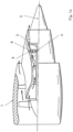
- FIG 1a shows a turbomachine 1 in a partially sectioned side view, specifically a jet engine.
- Figure 1b shows a schematic detailed view
- the turbomachine 1 is divided into a compressor, a combustion chamber and a turbine. Both the compressor and the turbine are made up of several stages (not shown), each stage consists of a guide vane and a rotor blade ring. During operation, the rotor blade rings rotate about the longitudinal axis 2 of the turbomachine 1.
- the turbine shaft 3 is guided in a bearing 4, which is held by support struts 5 (partly dashed) in the rest of the turbomachine 1.
- each of the support struts 5 is encased for aerodynamic and thermal reasons, namely by a component 6, which represents a covering and is also referred to as a fairing .
- the method according to the invention has proven to be particularly advantageous when coating fairings or panels, because certain areas are machined after the coating process.
- coating certain areas by spraying and/or brushing (also known as "touch-up” coating)
- cracking can be avoided by local removal of the coating during subsequent process steps.
- complex, complete covering for local coating by means of gas phase deposition which is not according to the invention, can also be avoided.
- Figure 2 shows such a cladding in an oblique view, not shown are the inner and outer cover strip sections, which are typically formed in one casting.
- the cladding has a front edge 21 and a rear edge 22 in relation to the hot gas flow 20, as well as two opposing side surfaces 23a,b connecting the front and rear edges 21, 22 to one another.
- the front and rear edges 21, 22 are each provided with a coating 24.
- the coatings 24a,b cover the edges 21, 22 over the greater part of their extent, but conversely leave the side surfaces 23a,b partially uncoated. This is for aerodynamic reasons, see the introduction to the description in detail. Such a coating only in certain areas can be achieved in a particularly advantageous manner using the method described below.
- Figure 3a shows a schematic section of the component 6 in an area that is coated.
- the component is made of a nickel alloy and is coated with aluminum, which is not deposited from the gas phase onto the uncoated surface 30 of the component 6. Instead, the aluminum is held in the form of particles 31 in a binder 32, and this suspension, i.e. the particle-displaced binder 32, is applied to the uncoated component surface 30.
- the binder 32 can be based on epoxy resin, for example, the particles 31 are added and evenly distributed, for example by stirring, before application.
- the suspension can be sprayed on in a similar way to paint.
- the component 6, onto which a layer 33 of the particle-mixed binder 32 has been applied is heat-treated at a temperature of around 980°C.
- the binder 32 pyrolyzes and evaporates on the one hand, and the aluminum also diffuses proportionally into the surface 30 of the component 6 on the other.
- the coating material 35 i.e. the aluminum, is partly located on the surface 30, but is also partially diffused in. The result is a coating which protects the areas on and around the front and rear edges 21, 22 that are particularly susceptible to oxidation well against oxidation.
- Turbomachine 1 Longitudinal axis 2 Turbine shaft 3 Warehouse 4 Support strut 5 Component 6 Front edge 21 Trailing edge 22 Side surfaces 23a, b Area 24a, b surface 30 Particles 31 Binders 32 Position 33 Coating material 35
Landscapes
- Chemical & Material Sciences (AREA)
- Engineering & Computer Science (AREA)
- Mechanical Engineering (AREA)
- Materials Engineering (AREA)
- Chemical Kinetics & Catalysis (AREA)
- Metallurgy (AREA)
- Organic Chemistry (AREA)
- General Engineering & Computer Science (AREA)
- Turbine Rotor Nozzle Sealing (AREA)
- Application Of Or Painting With Fluid Materials (AREA)
- Other Surface Treatments For Metallic Materials (AREA)
Description
- Die vorliegende Erfindung betrifft ein Verfahren zum Beschichten eines Bauteils, das zum Anordnen im Heißgaskanal einer Strömungsmaschine vorgesehen ist.
- Bei der Strömungsmaschine kann es sich bspw. um ein Strahltriebwerk handeln, z. B. um ein Mantelstromtriebwerk. Funktional gliedert sich die Strömungsmaschine in Verdichter, Brennkammer und Turbine. Etwa im Falle des Strahltriebwerks wird angesaugte Luft vom Verdichter komprimiert und in der nachgelagerten Brennkammer mit hinzugemischtem Kerosin verbrannt. Das entstehende Heißgas, eine Mischung aus Verbrennungsgas und Luft, durchströmt die nachgelagerte Turbine und wird dabei expandiert. Das vom Heißgas durchströmte Volumen, also der Pfad von einschließlich der Brennkammer über die Turbine bis zur Düse wird als "Heißgaskanal" bezeichnet.
- Verschiedene Verfahren zum Beschichten von Bauteilen sind aus den Dokumenten
EP1528117A1 ,US20060177686A1 ,WO2013149609A1 ,DE102009008510A1 ,WO2006061431A2 undEP2371986A1 bekannt. - Der vorliegende Gegenstand richtet sich auf ein zum Anordnen im Heißgaskanal vorgesehenes Bauteil, soll dabei aber zunächst ausdrücklich nicht auf das zur Illustration in Bezug genommene Strahltriebwerk beschränkt sein. Bei der Strömungsmaschine kann es sich bspw. auch um eine stationäre Gasturbine handeln.
- Der vorliegenden Erfindung liegt das technische Problem zugrunde, ein besonders vorteilhaftes Verfahren zum Beschichten eines zum Anordnen im Heißgaskanal einer Strömungsmaschine vorgesehenen Bauteils anzugeben.
- Erfindungsgemäß wird diese Aufgabe mit dem Verfahren gemäß Anspruch 1 gelöst. Auf die unbeschichtete Oberfläche des Bauteils wird also zunächst ein Bindemittel aufgebracht, welches das Beschichtungsmaterial bzw. eine Vorstufe davon in Partikelform enthält. Das bereichsweise mit dem Partikel-versetzten Bindemittel bedeckte Bauteil wird dann wärmebehandelt, wobei sich das Bindemittel auflöst und das Beschichtungsmaterial an dem Bauteil verbleibt (an der Oberfläche bzw. auch eindiffundiert).
- Bevorzugte Ausführungsformen finden sich in den abhängigen Ansprüchen und der gesamten Beschreibung, wobei in der Darstellung der Merkmale nicht immer im Einzelnen zwischen dem Beschichtungsverfahren und einem Herstellungsverfahren, im Zuge dessen beschichtet wird, bzw. einem entsprechenden Bauteil unterschieden wird. Generell ist die Offenbarung hinsichtlich sämtlicher Anspruchskategorien zu lesen.
- Mit der Beschichtung kann bspw. ein Bereich des Bauteils geschützt werden, der z. B. aufgrund einer hohen Strömungsgeschwindigkeit bzw. Temperatur des Heißgases besonders oxidations- bzw. heißgaskorrosionsgefährdet ist. Umgekehrt haben die Erfinder festgestellt, dass ein Beschichten der gesamten heißgaszugewandten Oberfläche aerodynamisch nachteilig sein kann, weil die Beschichtung in der Regel eine rauere Oberfläche als bspw. ein unbeschichtetes, geschliffenes bzw. poliertes Bauteil hat. Eine Nachbearbeitung der Beschichtung selbst, etwa durch spanende Bearbeitung, kann andererseits z. B. hinsichtlich einer Rissbildung in angrenzenden Schichtbereichen problematisch und deswegen weniger erwünscht sein (eine Nachbearbeitung durch Gleitschleifen wäre denkbar, damit können aber die geringen Rauheiten polierter Oberflächen nicht oder nur schwer erreicht werden). Idealerweise wird deshalb nur ein im Besonderen oxidationsgefährdeter Bereich der Bauteiloberfläche beschichtet.
- Eine solche nur bereichsweise Beschichtung der Oberfläche lässt sich mit dem vorgeschlagenen Verfahren in vorteilhafter Weise erreichen. Das Partikel-versetzte Bindemittel kann nämlich einem Lack vergleichbar gezielt auf den zu beschichtenden Bereich aufgebracht werden. Bei einem Aufsprühen des Bindemittels können der zu beschichtende Bereich und ein angrenzender von der Beschichtung auszunehmender Bereich bspw. mit einer einfachen, nur lokalen Maske definiert werden. Alternativ kann das Partikel-versetzte Bindemittel auch aufgepinselt oder aufgestrichen werden, wofür eine Maske nicht notwendig sein muss. Wollte man das Beschichtungsmaterial alternativ und anders als gemäß der vorliegenden Erfindung bspw. aus der Gasphase abscheiden, müsste das Bauteil hingegen aufgrund der ungerichteten, allseitig wirksamen Abscheidung weit aufwändiger und nahezu vollumfänglich abgedeckt werden, wobei lediglich die zu beschichtenden Bereiche unabgedeckt belassen werden könnten. Insbesondere kleine Bauteile können aber selbstverständlich auch insgesamt bzw. an ihrer gesamten heißgaszugewandten Oberfläche beschichtet werden (der aerodynamische Einfluss kann hier geringer sein, im Vergleich zu einer nicht erfindungsgemäßen Gasphasenabscheidung in Verbindung mit der Abdeckung von Funktionsflächen können sich wirtschaftliche Vorteile ergeben).
- Eine solche lediglich bereichsweise Beschichtung, bei der bestimmte Bereiche unbeschichtet bleiben, ist auch vorteilhaft gegenüber einer vollständigen Beschichtung mit einer nachträglichen bereichsweisen Entfernung der Beschichtung, beispielsweise von spanend zu bearbeitenden Funktionsflächen. Damit kann nämlich das Risiko einer Rissbildung in der Beschichtung aufgrund der Entfernung vermieden werden.
- Generell sind im Rahmen dieser Offenbarung "ein" und "eine" als unbestimmte Artikel und damit ohne ausdrückliche gegenteilige Angabe immer auch als "mindestens ein" bzw. "mindestens eine" zu lesen. Soweit also bspw. davon die Rede ist, dass "ein Bereich" der Bauteiloberfläche beschichtet wird, ist dies selbstverständlich nicht dahingehend zu lesen, dass nur ein einziger Bereich beschichtet werden soll, die Beschichtung mehrerer Bereiche kann sogar bevorzugt sein (vgl. das Ausführungsbeispiel zur Illustration).
- Das Beschichtungsmaterial wird auf die "unbeschichtete" Bauteiloberfläche des unbeschichteten Bauteils aufgebracht, das Bauteil wurde also insgesamt nicht bereits zuvor beschichtet. Als "Beschichtung" wird hierbei eine Schicht auf der Oberfläche verstanden, die insoweit dauerhaft ist, als sie sich im Zuge der Wärmebehandlung nicht auflösen würde. Im Allgemeinen ist also bspw. denkbar, dass vor dem Aufbringen des Partikel-versetzten Bindematerials eine Lage des Bindemittels ohne Partikelbeigabe aufgebracht wird (diese Lage wäre insofern keine Schicht, als sie sich im Zuge der Wärmebehandlung auflösen würde). Bevorzugt wird das Partikel-versetzte Bindemittel jedoch direkt auf die Bauteiloberfläche selbst aufgebracht, also unmittelbar an jenen Werkstoff grenzend, aus dem das Bauteil vorgesehen ist. Die aufgebrachte Lage des Partikel-versetzten Bindemittels kann bspw. pro Bereich eine Fläche von mindestens 10 cm2, 20 cm2bzw. 30 cm2 haben (mögliche Obergrenzen hängen von der Bauteilgröße ab, können aber bspw. bei höchstens 200 cm2 bzw. 100 cm2 liegen).
- In das Bindemittel sind die Partikel eingebettet. Bevorzugt ist ein flüssiges Bindemittel, das insbesondere zähflüssig (hochviskos) sein kann. Die Partikel und das Bindemittel bilden bevorzugt eine Suspension, diese kann bspw. unmittelbar vor dem Aufbringen durchmischt werden, etwa mit einem Rührer, um eine möglichst gleichmäßige Verteilung der Partikel zu erreichen. Das Bindemittel kann bspw. auf Polymerbasis vorgesehen sein, etwa als Dispersion in wässriger Lösung oder in einem anderen Lösemittel. Das Bindemittel kann auch Bestandteile aufweisen, die sich bereits vor der Wärmebehandlung, beim Trocknen der aufgetragenen Lage verflüchtigen. Auch nach einem etwaigen Trocknen verbleibt jedoch ein Teil des Bindemittels, der sich dann im Zuge der Wärmebehandlung auflöst und bspw. abdampft bzw. -raucht.
- Im Allgemeinen ist auch ein Beschichtungsmaterial denkbar, das erst im Zuge der Wärmebehandlung seine endgültige chemische Struktur annimmt. Deshalb kann das Bindemittel auch mit einer Vorstufe des Beschichtungsmaterials versetzt sein, die in einer während der Wärmebehandlung ablaufenden chemischen Reaktion in das Schichtmaterial umgewandelt wird (eine solche Vorstufe kann auch mehrkomponentig sein). Bevorzugt ist das Beschichtungsmaterial jedoch dem Bindemittel bereits in seiner endgültigen chemischen Form, als Element oder Verbindung beigegeben.
- Bei einer bevorzugten Ausführungsform weisen die Partikel Aluminium auf, das bei der Wärmebehandlung anteilig in die Oberfläche des Bauteils eindiffundiert. Es sind bspw. auch Partikel aus einer Aluminiumlegierung denkbar, bevorzugt sind Partikel, die im Rahmen des technisch Üblichen aus Reinaluminium bestehen. Alternativ wäre im Allgemeinen bspw. auch ein keramisches Beschichtungsmaterial denkbar. Das Bauteil ist generell bevorzugt ein Metallbauteil, also aus einem metallischen Werkstoff vorgesehen, bspw. einer Legierung. Ganz allgemein kann für das Bauteil ein hochtemperaturfester Werkstoff vorteilhaft sein.
- In bevorzugter Ausgestaltung ist das Bauteil aus einer Nickellegierung vorgesehen. Dies bezieht sich auf das Bauteil von dem Beschichtungsmaterial abgesehen; in Verbindung mit der Nickellegierung ist letzteres besonders bevorzugt Aluminium, siehe vorne. Das Bauteil kann aus einer Nickelbasislegierung vorgesehen sein, bspw. auch aus einer Nickelbasis-Superlegierung, die durch Zulegieren weiterer Bestandteile hinsichtlich der Kriech- bzw. Ermüdungsfestigkeit optimiert sein kann. Es kann bspw. Titan und/oder Aluminium zulegiert sein, bzw. auch Chrom, Kobalt etc.
- Bei einer bevorzugten Ausführungsform ist das Bindemittel auf organischer Basis vorgesehen, bspw. auf Epoxidharz- oder Alkydharz-Basis. Das Bindemittel pyrolysiert bei der Wärmebehandlung und verdampft bzw. raucht ab.
- In bevorzugter Ausgestaltung beträgt die Temperatur bei der Wärmebehandlung mindestens 800 °C, weiter und besonders bevorzugt mindestens 850 °C bzw. 900 °C. Bevorzugte Obergrenzen können bspw. bei höchstens 1200 °C, 1150 °C, 1100 °C bzw. 1050 °C liegen, wobei die Obergrenzen im Allgemeinen auch unabhängig von den Untergrenzen offenbart sein sollen, und umgekehrt. Das Bauteil kann bspw. für eine Zeitdauer von mindestens 30 Minuten bzw. 60 Minuten in einem entsprechenden Temperaturbereich gehalten werden, mit möglichen (davon unabhängigen) Obergrenzen bei bspw. höchstens 24 Stunden bzw. 12 Stunden. Besonders bevorzugt kann eine Temperatur von rund 980 °C sein. Insbesondere im Falle des vorstehend genannten Aluminiums kann die Wärmebehandlung auch als Diffusionsglühen betrachtet werden, bei dem sich nicht nur das Bindemittel auflöst, sondern das Aluminium auch in die Oberfläche des Bauteils eindiffundiert.
- Von der gesamten heißgaszugewandten Oberfläche des Bauteils wird ein Flächenanteil von mindestens 10 %, weiter und besonders bevorzugt mindestens 15 % bzw. 20 %, mit dem Partikel-versetzten Bindemittel beschichtet; die "heißgaszugewandte Oberfläche" ist der im Heißgaskanal von dem Heißgas umströmte Teil der gesamten Bauteiloberfläche. Im Allgemeinen auch unabhängig von den Untergrenzen liegen bevorzugte Obergrenzen bei höchstens 80 %, 70 %, 60 % bzw. 50 % (in der Reihenfolge der Nennung zunehmend bevorzugt). Es können aber zusätzlich oder alternativ auch heißgasabgewandte Oberflächenbereiche des Bauteils beschichtet werden (die außerhalb des Heißgaskanals liegen). Auch diese können oxidationsgefährdet sein, bspw. entsprechend heiße Zonen im Sekundär-Luftsystem.
- Umgekehrt ist also bei dem fertig beschichteten Bauteil bspw. ein Anteil von mindestens 20 %, 30 %, 40 % bzw. 50 % der heißgaszugewandten Oberfläche unbeschichtet, dann also in direktem Kontakt mit dem Heißgas. Dies kann zunächst, wie vorstehend geschildert, hinsichtlich der Aerodynamik Vorteile bieten, weil die unbeschichtete Oberfläche geglättet werden bzw. sein kann, bspw. durch Polieren. Wenngleich im Allgemeinen auch eine glättende Nachbehandlung der Beschichtung selbst denkbar ist, bspw. durch Gleitschleifen, erfolgt bevorzugt keine Nachbearbeitung. Die Bauteiloberfläche wird bevorzugt vor dem Beschichten geglättet, insb. geschliffen (auch unabhängig von den genannten Flächenanteilen).
- Von der gesamten Bauteiloberfläche bleibt zumindest ein Funktionsflächenbereich unbeschichtet. Dieser Funktionsflächenbereich stellt, wenn das Bauteil in der Strömungsmaschine mit (einem) anderen Bauteil(en) zusammengebaut wird eine Montagegrenze dar. Es kann sich bspw. um eine Anlagefläche handeln, mit der das Bauteil dann an einem anderen Bauteil anliegt. Dabei ist es hinsichtlich der Maßhaltigkeit und damit Passgenauigkeit vorteilhaft, wenn der Funktionsflächenbereich im fertig beschichteten Bauteil unbeschichtet bleibt. Auch in dieser Hinsicht kann ein Vorteil des vorliegend beschriebenen Verfahrens, die gute Möglichkeit des bereichsweise selektiven Aufbringens, im Besonderen zum Tragen kommen (bei der nicht erfindungsgemäßen Gasphasenabscheidung würde das Abdecken der Funktionsflächenbereiche deutlich mehr Aufwand verursachen).
- Bei einer bevorzugten Ausführungsform wird das Partikel-versetzte Bindemittel vor der Wärmebehandlung sequentiell in mehreren Lagen aufgebracht. Es wird also zunächst eine erste Lage direkt auf die Bauteiloberfläche aufgebracht und anschließend mindestens eine weitere Lage auf zumindest einen Bereich der ersten Lage und ggf. anteilig auch einen bis dahin unbedeckten Oberflächenbereich. Die Lagen sollen zumindest einen Überlapp haben, sie können auch deckungsgleich sein. Mit dem sequentiellen Aufbringen kann bspw. einer Schlierenbildung bzw. einem ungleichmäßigen Partikelauftrag vorgebeugt werden, es lässt sich also gut reproduzierbar die je Flächenbereich gewünschte Menge an Beschichtungsmaterial einstellen. Nach dem Aufbringen einer Lage und vor dem Aufbringen der darauf folgenden wird bevorzugt getrocknet, bspw. bei einer Temperatur von mindestens 50 °C, bevorzugt 100 °C, wobei mögliche Obergrenzen (davon unabhängig) bspw. bei höchstens 250 °C bzw. 200 °C liegen können. Alternativ oder zusätzlich kann bspw. auch durch UV-Bestrahlung getrocknet werden. Bevorzugt wird nach dem Aufbringen jeder der Lagen getrocknet.
- Werden mehrere Lagen aufgebracht, kann auch ein nur teilweiser, nicht vollständiger Überlapp dieser Lagen von Interesse sein. So können die Lagen bspw. in einem besonders oxidationsgefährdeten Bereich (z. B. an Vorder- und/oder Hinterkante, siehe unten im Detail) überlappen. In einem Übergang zu einem weniger oxidationsgefährdeten Bereich (z. B. den Seitenflächen) kann dann auch nur eine Lage aufgebracht sein, sodass also ein gewisser (gestufter) Verlauf eingestellt wird. Mit den im oxidationsgefährdeten Bereich überlappenden Lagen wird dort im Verhältnis mehr Beschichtungsmaterial aufgebracht. Mit der nur einen Lage ist in dem Übergangsbereich weniger Beschichtungsmaterial vorhanden (dort wird auch weniger benötigt), was bspw. hinsichtlich einer geringeren Oberflächenrauigkeit und damit aerodynamisch, aber auch strukturmechanisch von Vorteil sein kann.
- Im Folgenden wird das Bauteil an sich weiter im Detail erläutert.
- In bevorzugter Ausgestaltung hat es in Bezug auf die Umströmung in dem Heißgaskanal eine Vorder- und eine Hinterkante, sowie zwei sich jeweils zwischen Vorder- und Hinterkante erstreckende Seitenflächen. Das Bauteil kann als Verkleidung im Turbinenzwischengehäuse dienen (siehe unten). Unabhängig davon im Einzelnen wird bzw. werden bevorzugt die Vorder- und/oder die Hinterkante mit der Beschichtung bedeckt, besonders bevorzugt beide. Bezogen auf die Erstreckung, welche die entsprechende Kante (Vorder- oder Hinterkante) hat, soll die Beschichtung jedenfalls einen größeren Teil davon bedecken, also mindestens 50 %, 60 %, 70 % bzw. 80 % (in der Reihenfolge der Nennung zunehmend bevorzugt). Bevorzugt bleiben die Seitenflächen jeweils zumindest bereichsweise unbeschichtet, was aerodynamisch vorteilhaft sein kann (siehe vorne). Eine jeweilige Beschichtung kann sich um die entsprechende Kante und dabei durchaus noch in die beiden Seitenflächen hinein erstrecken, soll dabei aber nicht durchgehend bis zur jeweilig anderen Kante vorliegen.
- Das Bauteil ist zum Anordnen in einem Turbinenzwischengehäuse (Turbine Center Frame) vorgesehen. Es kann sich bei dem Bauteil bspw. auch um ein sogenanntes Panel (auch als Heißgaskanalplatte bezeichnet) handeln, das im Innen- oder Außendeckband angeordnet wird.
- In alternativer und bevorzugter Ausgestaltung ist das Bauteil im Turbinenzwischengehäuse als Verkleidung einer das Lager der Turbinenwelle tragenden Stützstrebe vorgesehen. Das Lager der Turbinenwelle wird umlaufend, bezogen auf einen Umlauf um die Drehachse der Turbinenwelle, von mehreren Stützstreben getragen, die aus aerodynamischen und thermischen Gründen verkleidet werden. Diese Verkleidungen werden auch Fairings genannt. Eine solche Verkleidung hat Vorder- und Hinterkante sowie Seitenflächen (siehe vorne), ist also im Prinzip wie eine Leitschaufel aufgebaut. Bezüglich der bevorzugten Beschichtung von Vorder- und Hinterkante wird auf die vorstehenden Anmerkungen verwiesen.
- Bei einer bevorzugten Ausführungsform wird der zu beschichtende Bereich mit einer Maske maskiert, wird also ein umgebender Oberflächenbereich abgedeckt. Wenngleich im Allgemeinen bspw. auch ein Auftrag des Partikel-versetzten Bindemittels durch Streichen oder Drucken denkbar ist, wird es bevorzugt gesprüht. Die Maske verhindert dabei einen Partikelauftrag auf Bereiche, die unbeschichtet bleiben sollen. Bevorzugt ist eine Maske, die als im Gesamten für sich zusammenhängendes Teil an das Bauteil angehalten wird, bevorzugt nicht verklebt wird, was einen hohen Durchsatz ermöglicht. Bevorzugt hat die Maske eine zu einer Oberflächenkontur des Bauteils komplementäre Form und ist sie in dem zu beschichtenden Bereich unterbrochen.
- Die Erfindung betrifft ferner ein Verfahren zum Herstellen eines beschichteten Bauteils gemäß Anspruch 10.
- Im Folgenden wird die Erfindung anhand eines Ausführungsbeispiels näher erläutert, wobei die einzelnen Merkmale im Rahmen der nebengeordneten Ansprüche auch in anderer Kombination erfindungswesentlich sein können und auch weiterhin nicht im Einzelnen zwischen den unterschiedlichen Anspruchskategorien unterschieden wird.
- Im Einzelnen zeigt
- Figur 1a
- ein Strahltriebwerk in einer teilweise geschnittenen Seitenansicht, schematischen Ansicht;
- Figur 1b
- eine schematische Detailansicht zu
Figur 1a ; - Figur 2
- in einer Seitenansicht eine Verkleidung einer Stützstrebe aus dem Turbinenzwischengehäuse;
- Figur 3a
- einen schematischen Schnitt durch einen Bereich des Bauteils gemäß
Figur 2 zur Illustration eines Zwischenschritts des Beschichtungsverfahrens; - Figur 3b
- ebenfalls in einem Schnitt eine gemäß dem Beschichtungsverfahren hergestellte Schicht.
-
Figur 1a zeigt eine Strömungsmaschine 1 in einer teilweise geschnittenen Seitenansicht, konkret ein Strahltriebwerk.Figur 1b zeigt eine schematische Detailansicht dazu, die folgenden Anmerkungen beziehen sich auf beide Figuren. Funktional gliedert sich die Strömungsmaschine 1 in Verdichter, Brennkammer und Turbine. Sowohl der Verdichter als auch die Turbine sind jeweils aus mehreren Stufen aufgebaut (nicht dargestellt), jede Stufe setzt sich aus einem Leit- und einem Laufschaufelkranz zusammen. Die Laufschaufelkränze rotieren im Betrieb um die Längsachse 2 der Strömungsmaschine 1. Die Turbinenwelle 3 ist in einem Lager 4 geführt, das von Stützstreben 5 (teils strichliert) in der übrigen Strömungsmaschine 1 gehalten wird. Im Bereich des Heißgaskanals ist jede der Stützstreben 5 aus aerodynamischen und auch thermischen Gründen ummantelt, nämlich von einem Bauteil 6, das eine Verkleidung darstellt und auch als Fairing bezeichnet wird. - Gerade bei der Beschichtung von Fairings bzw. Panels hat sich das erfindungsgemä-ße Verfahren als besonders vorteilhaft herausgestellt, weil bei diesen bestimmte Flächen nach dem Beschichtungsprozess spanend bearbeitet werden. Durch das bereichsweise Beschichten mittels Sprühen und/oder Pinseln (auch als sog. "Touch-up" coating bezeichnet) kann eine Rissbildung durch ein lokales Entfernen der Beschichtung während nachfolgender Prozessschritte vermieden werden. Zudem kann auch ein aufwändiges vollumfängliches Abdecken für eine lokale Beschichtung mittels nicht erfindungsgemäßer Gasphasenabscheidung vermieden werden.
-
Figur 2 zeigt eine solche Verkleidung in einer Schrägansicht, nicht dargestellt sind die typischerweise in einem Guss damit geformten Innen- und Außendeckbandabschnitte. Die Verkleidung weist in Bezug auf die Heißgasströmung 20 eine Vorderkante 21 und eine Hinterkante 22 auf, sowie ferner zwei jeweils Vorder- und Hinterkante 21, 22 miteinander verbindende, einander entgegengesetzte Seitenflächen 23a,b. Die Vorder- und die Hinterkante 21, 22 sind jeweils mit einer Beschichtung 24 versehen. Die Beschichtungen 24a,b bedecken die Kanten 21, 22 jeweils über den größeren Teil ihrer Erstreckung, lassen aber umgekehrt die Seitenflächen 23a,b teilweise unbeschichtet. Dies hat aerodynamische Gründe, vgl. die Beschreibungseinleitung im Detail. Eine solche nur bereichsweise Beschichtung lässt sich mit dem nachstehend beschriebenen Verfahren im besonders vorteilhafter Weise erreichen. -
Figur 3a zeigt einen schematischen Schnitt des Bauteils 6 in einem Bereich, der beschichtet wird. Das Bauteil ist aus einer Nickellegierung vorgesehen und wird mit Aluminium beschichtet, das allerdings nicht aus der Gasphase auf die unbeschichtete Oberfläche 30 des Bauteils 6 abgeschieden wird. Stattdessen wird das Aluminium in Form von Partikeln 31 in einem Bindemittel 32 vorgehalten, und es wird diese Suspension, also das Partikel-versetzte Bindemittel 32, auf die unbeschichtete Bauteiloberfläche 30 aufgebracht. Das Bindemittel 32 kann bspw. auf Epoxidharz-Basis vorgesehen sein, die Partikel 31 werden beigegeben und bspw. durch Verrühren vor dem Aufbringen gleichmäßig verteilt. Die Suspension kann einem Lack vergleichbar aufgesprüht werden. - In einem nächsten Schritt wird das Bauteil 6, auf das eine Lage 33 des Partikel-versetzten Bindemittels 32 aufgebracht wurde, bei einer Temperatur von rund 980°C wärmebehandelt. Bei diesem Diffusionsglühen pyrolysiert und verdampft einerseits das Bindemittel 32, andererseits diffundiert das Aluminium anteilig auch in die Oberfläche 30 des Bauteils 6 ein. Dies zeigt
Figur 3b , das Beschichtungsmaterial 35, also das Aluminium, befindet sich zu einem Teil an der Oberfläche 30, ist aber anteilig auch eindiffundiert. Es resultiert eine Beschichtung, welche die besonders oxidationsgefährdeten Bereiche an und um Vorder- und Hinterkante 21,22 gut vor einer Oxidation schützt. -
Strömungsmaschine 1 Längsachse 2 Turbinenwelle 3 Lager 4 Stützstrebe 5 Bauteil 6 Vorderkante 21 Hinterkante 22 Seitenflächen 23a, b Bereich 24a, b Oberfläche 30 Partikel 31 Bindenmittel 32 Lage 33 Beschichtungsmaterial 35
Claims (10)
- Verfahren zum nur bereichsweisen Beschichten eines insgesamt nicht bereits zuvor beschichteten Bauteils (6) mit einem Beschichtungsmaterial (35), welches Bauteil (6) zum Anordnen im Heißgaskanal in einem Turbinenzwischengehäuse einer Strömungsmaschine (1) als Panel, also als Heißgaskanalplatte, oder als Fairing, also als Verkleidung einer das Lager (4) der Turbinenwelle (3) tragenden Stützstrebe (5), vorgesehen ist,
in welchem Verfahren- das Beschichtungsmaterial (35) oder eine Vorstufe davon in Form von Partikeln (31) in Mischung mit einem Bindemittel (32) vorgehalten wird;- auf einen Bereich (24a,b) einer unbeschichteten Oberfläche (30) des Bauteils (6) eine Lage (33) des Partikel-versetzten Bindemittels (32) aufgebracht wird;- das Bauteil (6) mit dem Partikel-versetzten Bindemittel (32) darauf derart wärmebehandelt wird, dass sich das Bindemittel (32) auflöst und das Beschichtungsmaterial (35) an dem Bauteil (6) verbleibt;- ein spanend zu bearbeitender oder spanend bearbeiteter Funktionsflächenbereich der Oberfläche (30) des Bauteils (6), der hinsichtlich eines Zusammenbaus des Bauteils (6) mit anderen Bauteilen in der Strömungsmaschine (1) eine Montagegrenze und eine Anlagefläche, mit der das Bauteil an einem anderen Bauteil (6) anliegt, darstellt, im fertig beschichteten Bauteil (6) unbeschichtet bleibt,
wobei in dem Verfahren von einem heißgaszugewandten Teil der Oberfläche (30) des Bauteils (6) ein Flächenanteil von mindestens 10 % beschichtet wird. - Verfahren nach Anspruch 1, bei welchem die Partikel (31) Aluminium aufweisen, das bei der Wärmebehandlung anteilig in die Oberfläche (30) des Bauteils (6) eindiffundiert, und/oder bei welchem die Lage durch Sprühen und/oder durch Aufpinseln, insbesondere lokal, aufgebracht wird.
- Verfahren nach Anspruch 1 oder 2, bei welchem das Bauteil (6) aus einer Nickellegierung vorgesehen ist.
- Verfahren nach einem der vorstehenden Ansprüche, bei welchem das Bindemittel (32) auf organischer Basis vorgesehen ist und bei der Wärmebehandlung pyrolysiert.
- Verfahren nach einem der vorstehenden Ansprüche, bei welchem bei mindestens 800 °C und höchstens 1200 °C wärmebehandelt wird.
- Verfahren nach einem der vorstehenden Ansprüche, bei welchem von einem heißgaszugewandten Teil der Oberfläche (30) des Bauteils (6) ein Flächenanteil von höchstens 80 % beschichtet wird.
- Verfahren nach einem der vorstehenden Ansprüche, bei welchem das Partikel-versetzte Bindemittel (32) vor der Wärmebehandlung sequenziell in mehreren Lagen (33) aufgebracht wird, die auf der Oberfläche (30) des Bauteils (6) miteinander zumindest einen Überlapp haben.
- Verfahren nach einem der vorstehenden Ansprüche, bei welchem das Bauteil (6) in Bezug auf eine Umströmung in dem Heißgaskanal eine Vorder- (21) und eine Hinterkante (22) hat, sowie ferner zwei die Vorder- (21) und die Hinterkante (22) miteinander verbindende Seitenflächen (23a,b) hat, wobei die Vorder- (21) und/oder die Hinterkante (22) über jeweils mindestens 50 %ihrer jeweiligen Erstreckung beschichtet werden, die Seitenflächen (23a,b) aber jeweils zumindest bereichsweise unbeschichtet bleiben.
- Verfahren nach einem der vorstehenden Ansprüche, bei welchem der Bereich (24a,b) der Oberfläche (30), auf den das Partikel-versetzte Bindemittel (32) aufgebracht wird, bei dem Aufbringen des Partikel-versetzten Bindemittels (32) mit einer Maske maskiert wird.
- Verfahren zum Herstellen eines beschichteten Bauteils (6), nämlich Fairings oder Panels, zum Anordnen im Heißgaskanal in einem Turbinenzwischengehäuse einer Strömungsmaschine (1), umfassend Beschichten des Bauteils (6) mit einem Verfahren nach einem der Ansprüche 1 bis 9.
Applications Claiming Priority (1)
| Application Number | Priority Date | Filing Date | Title |
|---|---|---|---|
| DE102017212075.4A DE102017212075A1 (de) | 2017-07-14 | 2017-07-14 | Verfahren zum Beschichten eines Bauteils für den Heißgaskanal einer Strömungsmaschine |
Publications (2)
| Publication Number | Publication Date |
|---|---|
| EP3428308A1 EP3428308A1 (de) | 2019-01-16 |
| EP3428308B1 true EP3428308B1 (de) | 2024-09-04 |
Family
ID=62222471
Family Applications (1)
| Application Number | Title | Priority Date | Filing Date |
|---|---|---|---|
| EP18173498.9A Active EP3428308B1 (de) | 2017-07-14 | 2018-05-22 | Verfahren zum beschichten eines bauteils für den heissgaskanal einer strömungsmaschine |
Country Status (3)
| Country | Link |
|---|---|
| US (1) | US11359289B2 (de) |
| EP (1) | EP3428308B1 (de) |
| DE (1) | DE102017212075A1 (de) |
Families Citing this family (2)
| Publication number | Priority date | Publication date | Assignee | Title |
|---|---|---|---|---|
| US20240271537A1 (en) * | 2023-02-14 | 2024-08-15 | Raytheon Technologies Corporation | Machinable coating for damping |
| DE102023104545A1 (de) * | 2023-02-24 | 2024-08-29 | MTU Aero Engines AG | Verfahren zum zumindest bereichsweisen Erzeugen einer Oxidationsschutzschicht auf einem Bauteil einer thermischen Gasturbinel |
Family Cites Families (14)
| Publication number | Priority date | Publication date | Assignee | Title |
|---|---|---|---|---|
| US5607720A (en) * | 1994-08-03 | 1997-03-04 | Nd Industries, Inc. | Self locking internally threaded fastener and apparatus and process for making the same |
| GB2348439A (en) * | 1999-03-29 | 2000-10-04 | Chromalloy Uk Limited | Mask for diffusion coating |
| US6305077B1 (en) * | 1999-11-18 | 2001-10-23 | General Electric Company | Repair of coated turbine components |
| US6749356B1 (en) | 2003-06-03 | 2004-06-15 | Northrop Grumman Corporation | Touch-up coating applicator assembly for remote locations |
| US7390534B2 (en) * | 2003-10-31 | 2008-06-24 | General Electric Company | Diffusion coating process |
| US7546683B2 (en) | 2003-12-29 | 2009-06-16 | General Electric Company | Touch-up of layer paint oxides for gas turbine disks and seals |
| GB2421032A (en) * | 2004-12-11 | 2006-06-14 | Siemens Ind Turbomachinery Ltd | A method of protecting a component against hot corrosion |
| US7575815B2 (en) * | 2005-01-24 | 2009-08-18 | Battelle Memorial Institute | Aluminide coatings |
| US7597934B2 (en) * | 2006-02-21 | 2009-10-06 | General Electric Company | Corrosion coating for turbine blade environmental protection |
| DE102008039969A1 (de) * | 2008-08-27 | 2010-03-04 | Mtu Aero Engines Gmbh | Turbinenschaufel einer Gasturbine und Verfahren zum Beschichten einer Turbinenschaufel einer Gasturbine |
| DE102009008510A1 (de) * | 2009-02-11 | 2010-08-12 | Mtu Aero Engines Gmbh | Beschichtung und Verfahren zum Beschichten eines Werkstücks |
| SG173932A1 (en) | 2010-02-25 | 2011-09-29 | United Technologies Corp | Repair of a coating on a turbine component |
| US20110244138A1 (en) * | 2010-03-30 | 2011-10-06 | Schlichting Kevin W | Metallic coating for non-line of sight areas |
| WO2013149609A1 (de) * | 2012-04-03 | 2013-10-10 | Mtu Aero Engines Gmbh | Schlicker und verfahren zur herstellung einer aluminium-diffusionsschicht |
-
2017
- 2017-07-14 DE DE102017212075.4A patent/DE102017212075A1/de not_active Withdrawn
-
2018
- 2018-05-22 EP EP18173498.9A patent/EP3428308B1/de active Active
- 2018-07-12 US US16/033,984 patent/US11359289B2/en active Active
Also Published As
| Publication number | Publication date |
|---|---|
| US11359289B2 (en) | 2022-06-14 |
| EP3428308A1 (de) | 2019-01-16 |
| DE102017212075A1 (de) | 2019-01-17 |
| US20190017174A1 (en) | 2019-01-17 |
Similar Documents
| Publication | Publication Date | Title |
|---|---|---|
| DE602004008015T2 (de) | Abdeckung zum Schutz von Turbomaschinenschaufeln bei Oberflächenbehandlung | |
| EP2940324B1 (de) | Lagerkäfig und lagereinrichtung mit einem derartigen lagerkäfig sowie verfahren zum ausbilden, reparieren und/oder austauschen eines solchen lagerkäfigs | |
| DE102012212954B4 (de) | Kaltgesprühte und wärmebehandelte Beschichtung für Magnesium | |
| EP2993249A1 (de) | Oberflächenglättung von generativ hergestellten bauteilen und entsprechend hergestellte bauteile einer strömungsmaschine | |
| WO2011044876A1 (de) | Verfahren zur herstellung einer lauf- oder statorschaufel und eine derartige schaufel | |
| EP3153269B1 (de) | Reparatur verschlissener bauteiloberflächen | |
| DE102016120480A1 (de) | Verfahren zum Herstellen eines Strömungsmaschinenlaufrads | |
| EP3228415A1 (de) | Verfahren zur herstellung eines werkstücks durch beschichten und additives herstellen; entsprechendes werkstück | |
| DE69409498T2 (de) | Integrale Schaufel-Rotoreinheit | |
| EP2834387B1 (de) | Schlicker und verfahren zur herstellung einer aluminium-diffusionsschicht | |
| EP1816401B1 (de) | Strömungsmaschine | |
| EP2695964B1 (de) | Bauteilangepasste Schutzschicht | |
| EP2796588A1 (de) | Verfahren zur Herstellung einer Hochtemperaturschutzbeschichtung und entsprechend hergestelltes Bauteil | |
| EP3428308A1 (de) | Verfahren zum beschichten eines bauteils für den heissgaskanal einer strömungsmaschine | |
| EP1593445B1 (de) | Verfahren zum Herstellen eines hohlgegossenen Bauteils mit Innenbeschichtung | |
| WO2011144564A1 (de) | Lüfterrad mit einer katalysator-oberfläche für ein raumluft -abzugsgerät, raumluft-abzugsgerät mit einem solchen lüfterrad und verfahren zur herstellung eines solchen lüfterrades | |
| DE10337094A1 (de) | Einlaufbelag für Gasturbinen sowie Verfahren zur Herstellung desselben | |
| WO2004096493A1 (de) | Verfahren zum verrunden von kanten an bauteilen | |
| EP3525962B1 (de) | Verfahren zur herstellung eines gasturbinenbauteils | |
| EP2534280B1 (de) | Verfahren zur herstellung eines bauteils und ein derartiges bauteil | |
| DE29520280U1 (de) | Aluminiumgußrad für Kraftfahrzeuge | |
| DE102018201453A1 (de) | Verfahren zur schichtweisen Herstellung einer Maskierung | |
| DE102018212480A1 (de) | Additives Herstellungsverfahren mit selektivem Bestrahlen und gleichzeitigem Auftragen sowie Wärmebehandlung | |
| DE3613274C2 (de) | ||
| DE102006058678A1 (de) | Verfahren und Vorrichtung zum Oberflächenstrahlen eines Teilelements eines Bauteils einer Gasturbine |
Legal Events
| Date | Code | Title | Description |
|---|---|---|---|
| PUAI | Public reference made under article 153(3) epc to a published international application that has entered the european phase |
Free format text: ORIGINAL CODE: 0009012 |
|
| STAA | Information on the status of an ep patent application or granted ep patent |
Free format text: STATUS: THE APPLICATION HAS BEEN PUBLISHED |
|
| AK | Designated contracting states |
Kind code of ref document: A1 Designated state(s): AL AT BE BG CH CY CZ DE DK EE ES FI FR GB GR HR HU IE IS IT LI LT LU LV MC MK MT NL NO PL PT RO RS SE SI SK SM TR |
|
| AX | Request for extension of the european patent |
Extension state: BA ME |
|
| STAA | Information on the status of an ep patent application or granted ep patent |
Free format text: STATUS: REQUEST FOR EXAMINATION WAS MADE |
|
| 17P | Request for examination filed |
Effective date: 20190702 |
|
| RBV | Designated contracting states (corrected) |
Designated state(s): AL AT BE BG CH CY CZ DE DK EE ES FI FR GB GR HR HU IE IS IT LI LT LU LV MC MK MT NL NO PL PT RO RS SE SI SK SM TR |
|
| STAA | Information on the status of an ep patent application or granted ep patent |
Free format text: STATUS: EXAMINATION IS IN PROGRESS |
|
| 17Q | First examination report despatched |
Effective date: 20210315 |
|
| RIC1 | Information provided on ipc code assigned before grant |
Ipc: F01D 25/16 20060101ALI20231122BHEP Ipc: F01D 5/28 20060101ALI20231122BHEP Ipc: C23C 12/02 20060101ALI20231122BHEP Ipc: C23C 10/50 20060101ALI20231122BHEP Ipc: C23C 10/48 20060101ALI20231122BHEP Ipc: C23C 10/30 20060101ALI20231122BHEP Ipc: C23C 10/20 20060101ALI20231122BHEP Ipc: C23C 10/18 20060101ALI20231122BHEP Ipc: C23C 10/04 20060101AFI20231122BHEP |
|
| GRAP | Despatch of communication of intention to grant a patent |
Free format text: ORIGINAL CODE: EPIDOSNIGR1 |
|
| STAA | Information on the status of an ep patent application or granted ep patent |
Free format text: STATUS: GRANT OF PATENT IS INTENDED |
|
| INTG | Intention to grant announced |
Effective date: 20240108 |
|
| GRAJ | Information related to disapproval of communication of intention to grant by the applicant or resumption of examination proceedings by the epo deleted |
Free format text: ORIGINAL CODE: EPIDOSDIGR1 |
|
| STAA | Information on the status of an ep patent application or granted ep patent |
Free format text: STATUS: EXAMINATION IS IN PROGRESS |
|
| INTC | Intention to grant announced (deleted) | ||
| GRAP | Despatch of communication of intention to grant a patent |
Free format text: ORIGINAL CODE: EPIDOSNIGR1 |
|
| STAA | Information on the status of an ep patent application or granted ep patent |
Free format text: STATUS: GRANT OF PATENT IS INTENDED |
|
| INTG | Intention to grant announced |
Effective date: 20240503 |
|
| GRAS | Grant fee paid |
Free format text: ORIGINAL CODE: EPIDOSNIGR3 |
|
| GRAA | (expected) grant |
Free format text: ORIGINAL CODE: 0009210 |
|
| STAA | Information on the status of an ep patent application or granted ep patent |
Free format text: STATUS: THE PATENT HAS BEEN GRANTED |
|
| AK | Designated contracting states |
Kind code of ref document: B1 Designated state(s): AL AT BE BG CH CY CZ DE DK EE ES FI FR GB GR HR HU IE IS IT LI LT LU LV MC MK MT NL NO PL PT RO RS SE SI SK SM TR |
|
| REG | Reference to a national code |
Ref country code: GB Ref legal event code: FG4D Free format text: NOT ENGLISH |
|
| REG | Reference to a national code |
Ref country code: CH Ref legal event code: EP |
|
| REG | Reference to a national code |
Ref country code: IE Ref legal event code: FG4D Free format text: LANGUAGE OF EP DOCUMENT: GERMAN |
|
| REG | Reference to a national code |
Ref country code: DE Ref legal event code: R096 Ref document number: 502018015073 Country of ref document: DE |
|
| REG | Reference to a national code |
Ref country code: LT Ref legal event code: MG9D |
|
| REG | Reference to a national code |
Ref country code: NL Ref legal event code: MP Effective date: 20240904 |
|
| PG25 | Lapsed in a contracting state [announced via postgrant information from national office to epo] |
Ref country code: NO Free format text: LAPSE BECAUSE OF FAILURE TO SUBMIT A TRANSLATION OF THE DESCRIPTION OR TO PAY THE FEE WITHIN THE PRESCRIBED TIME-LIMIT Effective date: 20241204 |
|
| PG25 | Lapsed in a contracting state [announced via postgrant information from national office to epo] |
Ref country code: PL Free format text: LAPSE BECAUSE OF FAILURE TO SUBMIT A TRANSLATION OF THE DESCRIPTION OR TO PAY THE FEE WITHIN THE PRESCRIBED TIME-LIMIT Effective date: 20240904 Ref country code: FI Free format text: LAPSE BECAUSE OF FAILURE TO SUBMIT A TRANSLATION OF THE DESCRIPTION OR TO PAY THE FEE WITHIN THE PRESCRIBED TIME-LIMIT Effective date: 20240904 Ref country code: GR Free format text: LAPSE BECAUSE OF FAILURE TO SUBMIT A TRANSLATION OF THE DESCRIPTION OR TO PAY THE FEE WITHIN THE PRESCRIBED TIME-LIMIT Effective date: 20241205 |
|
| PG25 | Lapsed in a contracting state [announced via postgrant information from national office to epo] |
Ref country code: BG Free format text: LAPSE BECAUSE OF FAILURE TO SUBMIT A TRANSLATION OF THE DESCRIPTION OR TO PAY THE FEE WITHIN THE PRESCRIBED TIME-LIMIT Effective date: 20240904 |
|
| PG25 | Lapsed in a contracting state [announced via postgrant information from national office to epo] |
Ref country code: LV Free format text: LAPSE BECAUSE OF FAILURE TO SUBMIT A TRANSLATION OF THE DESCRIPTION OR TO PAY THE FEE WITHIN THE PRESCRIBED TIME-LIMIT Effective date: 20240904 |
|
| PG25 | Lapsed in a contracting state [announced via postgrant information from national office to epo] |
Ref country code: HR Free format text: LAPSE BECAUSE OF FAILURE TO SUBMIT A TRANSLATION OF THE DESCRIPTION OR TO PAY THE FEE WITHIN THE PRESCRIBED TIME-LIMIT Effective date: 20240904 |
|
| PG25 | Lapsed in a contracting state [announced via postgrant information from national office to epo] |
Ref country code: ES Free format text: LAPSE BECAUSE OF FAILURE TO SUBMIT A TRANSLATION OF THE DESCRIPTION OR TO PAY THE FEE WITHIN THE PRESCRIBED TIME-LIMIT Effective date: 20240904 Ref country code: RS Free format text: LAPSE BECAUSE OF FAILURE TO SUBMIT A TRANSLATION OF THE DESCRIPTION OR TO PAY THE FEE WITHIN THE PRESCRIBED TIME-LIMIT Effective date: 20241204 |
|
| PG25 | Lapsed in a contracting state [announced via postgrant information from national office to epo] |
Ref country code: RS Free format text: LAPSE BECAUSE OF FAILURE TO SUBMIT A TRANSLATION OF THE DESCRIPTION OR TO PAY THE FEE WITHIN THE PRESCRIBED TIME-LIMIT Effective date: 20241204 Ref country code: PL Free format text: LAPSE BECAUSE OF FAILURE TO SUBMIT A TRANSLATION OF THE DESCRIPTION OR TO PAY THE FEE WITHIN THE PRESCRIBED TIME-LIMIT Effective date: 20240904 Ref country code: NO Free format text: LAPSE BECAUSE OF FAILURE TO SUBMIT A TRANSLATION OF THE DESCRIPTION OR TO PAY THE FEE WITHIN THE PRESCRIBED TIME-LIMIT Effective date: 20241204 Ref country code: LV Free format text: LAPSE BECAUSE OF FAILURE TO SUBMIT A TRANSLATION OF THE DESCRIPTION OR TO PAY THE FEE WITHIN THE PRESCRIBED TIME-LIMIT Effective date: 20240904 Ref country code: HR Free format text: LAPSE BECAUSE OF FAILURE TO SUBMIT A TRANSLATION OF THE DESCRIPTION OR TO PAY THE FEE WITHIN THE PRESCRIBED TIME-LIMIT Effective date: 20240904 Ref country code: GR Free format text: LAPSE BECAUSE OF FAILURE TO SUBMIT A TRANSLATION OF THE DESCRIPTION OR TO PAY THE FEE WITHIN THE PRESCRIBED TIME-LIMIT Effective date: 20241205 Ref country code: FI Free format text: LAPSE BECAUSE OF FAILURE TO SUBMIT A TRANSLATION OF THE DESCRIPTION OR TO PAY THE FEE WITHIN THE PRESCRIBED TIME-LIMIT Effective date: 20240904 Ref country code: ES Free format text: LAPSE BECAUSE OF FAILURE TO SUBMIT A TRANSLATION OF THE DESCRIPTION OR TO PAY THE FEE WITHIN THE PRESCRIBED TIME-LIMIT Effective date: 20240904 Ref country code: BG Free format text: LAPSE BECAUSE OF FAILURE TO SUBMIT A TRANSLATION OF THE DESCRIPTION OR TO PAY THE FEE WITHIN THE PRESCRIBED TIME-LIMIT Effective date: 20240904 |
|
| PG25 | Lapsed in a contracting state [announced via postgrant information from national office to epo] |
Ref country code: NL Free format text: LAPSE BECAUSE OF FAILURE TO SUBMIT A TRANSLATION OF THE DESCRIPTION OR TO PAY THE FEE WITHIN THE PRESCRIBED TIME-LIMIT Effective date: 20240904 |
|
| PG25 | Lapsed in a contracting state [announced via postgrant information from national office to epo] |
Ref country code: IS Free format text: LAPSE BECAUSE OF FAILURE TO SUBMIT A TRANSLATION OF THE DESCRIPTION OR TO PAY THE FEE WITHIN THE PRESCRIBED TIME-LIMIT Effective date: 20250104 Ref country code: PT Free format text: LAPSE BECAUSE OF FAILURE TO SUBMIT A TRANSLATION OF THE DESCRIPTION OR TO PAY THE FEE WITHIN THE PRESCRIBED TIME-LIMIT Effective date: 20250106 |
|
| PG25 | Lapsed in a contracting state [announced via postgrant information from national office to epo] |
Ref country code: RO Free format text: LAPSE BECAUSE OF FAILURE TO SUBMIT A TRANSLATION OF THE DESCRIPTION OR TO PAY THE FEE WITHIN THE PRESCRIBED TIME-LIMIT Effective date: 20240904 Ref country code: SM Free format text: LAPSE BECAUSE OF FAILURE TO SUBMIT A TRANSLATION OF THE DESCRIPTION OR TO PAY THE FEE WITHIN THE PRESCRIBED TIME-LIMIT Effective date: 20240904 |
|
| PG25 | Lapsed in a contracting state [announced via postgrant information from national office to epo] |
Ref country code: EE Free format text: LAPSE BECAUSE OF FAILURE TO SUBMIT A TRANSLATION OF THE DESCRIPTION OR TO PAY THE FEE WITHIN THE PRESCRIBED TIME-LIMIT Effective date: 20240904 |
|
| PG25 | Lapsed in a contracting state [announced via postgrant information from national office to epo] |
Ref country code: CZ Free format text: LAPSE BECAUSE OF FAILURE TO SUBMIT A TRANSLATION OF THE DESCRIPTION OR TO PAY THE FEE WITHIN THE PRESCRIBED TIME-LIMIT Effective date: 20240904 |
|
| PG25 | Lapsed in a contracting state [announced via postgrant information from national office to epo] |
Ref country code: IT Free format text: LAPSE BECAUSE OF FAILURE TO SUBMIT A TRANSLATION OF THE DESCRIPTION OR TO PAY THE FEE WITHIN THE PRESCRIBED TIME-LIMIT Effective date: 20240904 Ref country code: SK Free format text: LAPSE BECAUSE OF FAILURE TO SUBMIT A TRANSLATION OF THE DESCRIPTION OR TO PAY THE FEE WITHIN THE PRESCRIBED TIME-LIMIT Effective date: 20240904 |
|
| REG | Reference to a national code |
Ref country code: DE Ref legal event code: R097 Ref document number: 502018015073 Country of ref document: DE |
|
| PGFP | Annual fee paid to national office [announced via postgrant information from national office to epo] |
Ref country code: DE Payment date: 20250519 Year of fee payment: 8 |
|
| PG25 | Lapsed in a contracting state [announced via postgrant information from national office to epo] |
Ref country code: DK Free format text: LAPSE BECAUSE OF FAILURE TO SUBMIT A TRANSLATION OF THE DESCRIPTION OR TO PAY THE FEE WITHIN THE PRESCRIBED TIME-LIMIT Effective date: 20240904 |
|
| PLBE | No opposition filed within time limit |
Free format text: ORIGINAL CODE: 0009261 |
|
| STAA | Information on the status of an ep patent application or granted ep patent |
Free format text: STATUS: NO OPPOSITION FILED WITHIN TIME LIMIT |
|
| PGFP | Annual fee paid to national office [announced via postgrant information from national office to epo] |
Ref country code: FR Payment date: 20250521 Year of fee payment: 8 |
|
| 26N | No opposition filed |
Effective date: 20250605 |
|
| PG25 | Lapsed in a contracting state [announced via postgrant information from national office to epo] |
Ref country code: SE Free format text: LAPSE BECAUSE OF FAILURE TO SUBMIT A TRANSLATION OF THE DESCRIPTION OR TO PAY THE FEE WITHIN THE PRESCRIBED TIME-LIMIT Effective date: 20240904 |
|
| REG | Reference to a national code |
Ref country code: CH Ref legal event code: H13 Free format text: ST27 STATUS EVENT CODE: U-0-0-H10-H13 (AS PROVIDED BY THE NATIONAL OFFICE) Effective date: 20251223 |
|
| PG25 | Lapsed in a contracting state [announced via postgrant information from national office to epo] |
Ref country code: LU Free format text: LAPSE BECAUSE OF NON-PAYMENT OF DUE FEES Effective date: 20250522 |
|
| PG25 | Lapsed in a contracting state [announced via postgrant information from national office to epo] |
Ref country code: CH Free format text: LAPSE BECAUSE OF NON-PAYMENT OF DUE FEES Effective date: 20250531 |
|
| REG | Reference to a national code |
Ref country code: BE Ref legal event code: MM Effective date: 20250531 |
|
| PG25 | Lapsed in a contracting state [announced via postgrant information from national office to epo] |
Ref country code: MC Free format text: LAPSE BECAUSE OF FAILURE TO SUBMIT A TRANSLATION OF THE DESCRIPTION OR TO PAY THE FEE WITHIN THE PRESCRIBED TIME-LIMIT Effective date: 20240904 |
|
| PGFP | Annual fee paid to national office [announced via postgrant information from national office to epo] |
Ref country code: GB Payment date: 20260324 Year of fee payment: 9 |
|
| PG25 | Lapsed in a contracting state [announced via postgrant information from national office to epo] |
Ref country code: IE Free format text: LAPSE BECAUSE OF NON-PAYMENT OF DUE FEES Effective date: 20250522 |
|
| PG25 | Lapsed in a contracting state [announced via postgrant information from national office to epo] |
Ref country code: BE Free format text: LAPSE BECAUSE OF NON-PAYMENT OF DUE FEES Effective date: 20250531 |