EP3428056A1 - Box structural arrangenment for an aircraft and manufacturing method thereof - Google Patents
Box structural arrangenment for an aircraft and manufacturing method thereof Download PDFInfo
- Publication number
- EP3428056A1 EP3428056A1 EP17382460.8A EP17382460A EP3428056A1 EP 3428056 A1 EP3428056 A1 EP 3428056A1 EP 17382460 A EP17382460 A EP 17382460A EP 3428056 A1 EP3428056 A1 EP 3428056A1
- Authority
- EP
- European Patent Office
- Prior art keywords
- aircraft
- structural arrangement
- box structural
- composite layers
- conduit
- Prior art date
- Legal status (The legal status is an assumption and is not a legal conclusion. Google has not performed a legal analysis and makes no representation as to the accuracy of the status listed.)
- Granted
Links
- 238000004519 manufacturing process Methods 0.000 title claims abstract description 7
- 239000002131 composite material Substances 0.000 claims abstract description 33
- 239000012858 resilient material Substances 0.000 claims abstract description 9
- 238000000034 method Methods 0.000 claims abstract description 7
- 239000006260 foam Substances 0.000 claims description 4
- 239000004033 plastic Substances 0.000 claims description 2
- 229920003023 plastic Polymers 0.000 claims description 2
- 238000009434 installation Methods 0.000 description 11
- 238000007689 inspection Methods 0.000 description 2
- 238000012423 maintenance Methods 0.000 description 2
- 239000003381 stabilizer Substances 0.000 description 2
- OKTJSMMVPCPJKN-UHFFFAOYSA-N Carbon Chemical compound [C] OKTJSMMVPCPJKN-UHFFFAOYSA-N 0.000 description 1
- 229920002430 Fibre-reinforced plastic Polymers 0.000 description 1
- 229910052799 carbon Inorganic materials 0.000 description 1
- 230000008878 coupling Effects 0.000 description 1
- 238000010168 coupling process Methods 0.000 description 1
- 238000005859 coupling reaction Methods 0.000 description 1
- 238000005553 drilling Methods 0.000 description 1
- 230000000694 effects Effects 0.000 description 1
- 238000005538 encapsulation Methods 0.000 description 1
- 239000011151 fibre-reinforced plastic Substances 0.000 description 1
- 238000003780 insertion Methods 0.000 description 1
- 230000037431 insertion Effects 0.000 description 1
- 239000011159 matrix material Substances 0.000 description 1
Images


Classifications
-
- B—PERFORMING OPERATIONS; TRANSPORTING
- B64—AIRCRAFT; AVIATION; COSMONAUTICS
- B64C—AEROPLANES; HELICOPTERS
- B64C3/00—Wings
- B64C3/18—Spars; Ribs; Stringers
- B64C3/185—Spars
-
- B—PERFORMING OPERATIONS; TRANSPORTING
- B64—AIRCRAFT; AVIATION; COSMONAUTICS
- B64C—AEROPLANES; HELICOPTERS
- B64C1/00—Fuselages; Constructional features common to fuselages, wings, stabilising surfaces or the like
- B64C1/06—Frames; Stringers; Longerons ; Fuselage sections
- B64C1/065—Spars
-
- B—PERFORMING OPERATIONS; TRANSPORTING
- B64—AIRCRAFT; AVIATION; COSMONAUTICS
- B64C—AEROPLANES; HELICOPTERS
- B64C3/00—Wings
- B64C3/20—Integral or sandwich constructions
-
- B—PERFORMING OPERATIONS; TRANSPORTING
- B64—AIRCRAFT; AVIATION; COSMONAUTICS
- B64C—AEROPLANES; HELICOPTERS
- B64C3/00—Wings
- B64C3/26—Construction, shape, or attachment of separate skins, e.g. panels
-
- B—PERFORMING OPERATIONS; TRANSPORTING
- B64—AIRCRAFT; AVIATION; COSMONAUTICS
- B64C—AEROPLANES; HELICOPTERS
- B64C5/00—Stabilising surfaces
- B64C5/02—Tailplanes
-
- B—PERFORMING OPERATIONS; TRANSPORTING
- B64—AIRCRAFT; AVIATION; COSMONAUTICS
- B64C—AEROPLANES; HELICOPTERS
- B64C5/00—Stabilising surfaces
- B64C5/06—Fins
-
- F—MECHANICAL ENGINEERING; LIGHTING; HEATING; WEAPONS; BLASTING
- F16—ENGINEERING ELEMENTS AND UNITS; GENERAL MEASURES FOR PRODUCING AND MAINTAINING EFFECTIVE FUNCTIONING OF MACHINES OR INSTALLATIONS; THERMAL INSULATION IN GENERAL
- F16L—PIPES; JOINTS OR FITTINGS FOR PIPES; SUPPORTS FOR PIPES, CABLES OR PROTECTIVE TUBING; MEANS FOR THERMAL INSULATION IN GENERAL
- F16L3/00—Supports for pipes, cables or protective tubing, e.g. hangers, holders, clamps, cleats, clips, brackets
-
- H—ELECTRICITY
- H02—GENERATION; CONVERSION OR DISTRIBUTION OF ELECTRIC POWER
- H02G—INSTALLATION OF ELECTRIC CABLES OR LINES, OR OF COMBINED OPTICAL AND ELECTRIC CABLES OR LINES
- H02G3/00—Installations of electric cables or lines or protective tubing therefor in or on buildings, equivalent structures or vehicles
- H02G3/02—Details
- H02G3/04—Protective tubing or conduits, e.g. cable ladders or cable troughs
- H02G3/0406—Details thereof
-
- H—ELECTRICITY
- H02—GENERATION; CONVERSION OR DISTRIBUTION OF ELECTRIC POWER
- H02G—INSTALLATION OF ELECTRIC CABLES OR LINES, OR OF COMBINED OPTICAL AND ELECTRIC CABLES OR LINES
- H02G3/00—Installations of electric cables or lines or protective tubing therefor in or on buildings, equivalent structures or vehicles
- H02G3/02—Details
- H02G3/04—Protective tubing or conduits, e.g. cable ladders or cable troughs
- H02G3/0437—Channels
-
- B—PERFORMING OPERATIONS; TRANSPORTING
- B64—AIRCRAFT; AVIATION; COSMONAUTICS
- B64C—AEROPLANES; HELICOPTERS
- B64C1/00—Fuselages; Constructional features common to fuselages, wings, stabilising surfaces or the like
- B64C2001/0054—Fuselage structures substantially made from particular materials
- B64C2001/0072—Fuselage structures substantially made from particular materials from composite materials
-
- Y—GENERAL TAGGING OF NEW TECHNOLOGICAL DEVELOPMENTS; GENERAL TAGGING OF CROSS-SECTIONAL TECHNOLOGIES SPANNING OVER SEVERAL SECTIONS OF THE IPC; TECHNICAL SUBJECTS COVERED BY FORMER USPC CROSS-REFERENCE ART COLLECTIONS [XRACs] AND DIGESTS
- Y02—TECHNOLOGIES OR APPLICATIONS FOR MITIGATION OR ADAPTATION AGAINST CLIMATE CHANGE
- Y02T—CLIMATE CHANGE MITIGATION TECHNOLOGIES RELATED TO TRANSPORTATION
- Y02T50/00—Aeronautics or air transport
- Y02T50/40—Weight reduction
Definitions
- the present invention refers to a new box structural arrangement for an aircraft, in particular, to be used in a wing, a horizontal tail plane (HTP) and a vertical tail plane (VTP) of an aircraft.
- HTP horizontal tail plane
- VTP vertical tail plane
- Another object of the invention is to provide a more reliable box for an aircraft that is capable of reducing the fatigue suffered by traditional boxes that are conventionally attached at discrete support points.
- the invention also refers to a method for manufacturing such a box structural arrangement.
- CFRP Carbon Fibre Reinforced Plastic
- these installations are done by connecting pipelines and harnesses at discrete points of structural components of the aircraft.
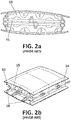
- FIGs 1 and 2 shows a conventional HTP (10) equipped with a hydraulic pipeline (15).
- the hydraulic pipeline (15) follows a longitudinal (spanwise) direction and crosses the HTP lateral boxes (16), causing openings (18) in the front (13) and rear HTP spars (14).
- Figure 2 shows a front view ( Figure 2a ) and a perspective view ( Figure 2b ) of one of the HTP lateral boxes (16) of Figure 1 in which the hydraulic pipeline (15) is shown crossing the front (13) and rear HTP spars (14).
- the present invention overcomes the above mentioned drawbacks by providing a box structural arrangement for an aircraft that simplifies the installation and maintenance tasks when pipes/lines/wirings have to be conducted through structural components of the aircraft.
- One aspect of the present invention refers to a box structural arrangement for an aircraft that comprises a first and second composite layers, at least one spar web extended between opposite edges of the first and second composite layers along a longitudinal direction, and a conduit piece extended between opposite edges of the first and second composite layers, and having a hollow section that comprises at least one conduit dimensioned to receive pipes or harnesses and surrounded by a resilient material.
- the conduit piece is mounted on the spar web to provide a channeled box structural arrangement.
- the invention provides a new box arrangement with a channeled designed to internally conduct pipelines and/or harnesses required for providing electrical or hydraulic supply in the aircraft.
- the invention minimizes the drilling of structural components of the aircraft to enable the passage of pipelines and/or harnesses through them.
- this channeled configuration allows connections/bifurcations are done from outside the integrated structure, which increase the reliability and integrity of the installation, and minimize the potential hydraulic leakages.
- this box arrangement is designed to attenuate the vibration or fatigue effects experienced by traditional box arrangements, which are equipped with discrete points of support for the passage of pipelines and/or harnesses.
- the invention provides a continuous support spreading loads through a larger area by mounting the conduit piece on the spar web, which extends along the first and second composite layers a longitudinal direction.
- Another aspects of the invention refers to a horizontal tail plane, a wing, and a vertical tail plane that comprises a box structural arrangement as described above.
- another aspect of the invention refers to a method for manufacturing a box structural arrangement for an aircraft, comprising the steps of providing a first and a second layer of composite material and at least one spar web extended between opposite edges of the first and second composite layers, arranging the spar web between opposite edges of the first and second composite layers along a longitudinal direction, providing a conduit piece extended between opposite edges of the first and second composite layers and having a hollow section comprising at least one conduit dimensioned to receive pipes or harnesses and surrounded by a resilient material, and mounting the conduit piece on the spar web to form a channeled box structural arrangement.
- the method of the invention provides a simple way of producing reliable boxes, which are specially designed to simplify the installation of pipelines and harnesses throughout the aircraft.
- Figures 3a and 3b show a box structural arrangement (1) for an aircraft according to a preferred embodiment.
- the box structural arrangement (1) comprises first (2) and second composite layers (3), at least one spar web (4) transversely arranged between the first (2) and second composite layers (3), and a conduit piece (5) mounted on the at least one spar web (4).
- the spar web (4) is extended between opposite edges (2a, 2b, 3a, 3b) of the first and second composite layers (2, 3) following a longitudinal direction.
- the spar web (4) has substantially the same length as the first (2) and second composite layers (3) to provide a continuous support to the conduit piece (5).
- the conduit piece (5) is also extended between opposite edges (2a, 2b, 3a, 3b) of the first and second composite layers (2, 3).
- the conduit piece (5) has similar (or same) length as the spar web (4) to provide continuous encapsulation (and support) for the pipes or harnesses (19) along the box structural arrangement (1).
- the hollow section (6) of the conduit piece (5) encloses two conduits (7) (channels or canals) surrounded by a resilient material (8).
- the conduits (7) are dimensioned to receive pipes or harnesses (19), which will be preferably coated by a hard cover (20) to provide rigidity and an easy insertion into the conduits (7).
- the conduits (7) may include a foam bed (21) to ease the introduction of pipes or harnesses (19).
- the conduit piece (5) preferably has an omega cross section with a flat mounting surface (9) to facilitate its coupling to the spar web (4).
- the resilient material (8) consists of foam or plastic.
- the invention refers to a horizontal tail plane (10) comprising the box structural arrangement (1) described above.
- Figures 5a and 5b show a perspective and cross sectional view of a horizontal tail plane (10).
- the horizontal tail plane (10) has upper (11) and lower skins (12), and forward (13) and rear spars (14) arranged along a spanwise direction.
- the horizontal tail plane (10) further comprises the box structural arrangement (1) described above, wherein the upper and lower skins (11, 12) comprises the first (2) and second composite layers (3), and wherein at least one conduit piece (5) is mounted on each one of the forward (13) and the rear spars (14).
- conduit piece (5) and the spar web (4) are preferably extended between the shortest opposite edges of the first and second composite layers (2, 3) following thus a spanwise direction.
- the invention provides an alternative installation concept that offers a clean and smooth surface for aerodynamic purposes.
- the potential extra weight of the conduit piece till the end of the stabilizer is compensated with the aerodynamic benefit of such a clean surface.
- the invention further refers to a wing and a vertical tail plane that comprises a box structural arrangement as described.
- the invention finally refers to a method for manufacturing a box structural arrangement (1) for an aircraft as described above.
- the method comprises the steps of:
- the large and single pieces of pipelines/harnesses may be easily installed from one side in the factory.
- stabilizers HTP, VTP
- connections/bifurcations can be done from outside their boxes, removing then the need for access panels (service doors) in the middle of these components.
- the potential extra weight is compensated with the cleanness of the surface that leads to aerodynamic benefits.
Abstract
Description
- The present invention refers to a new box structural arrangement for an aircraft, in particular, to be used in a wing, a horizontal tail plane (HTP) and a vertical tail plane (VTP) of an aircraft.
- More in particular, it is an object of the invention to provide a box structural arrangement that eases installation and maintenance tasks in the aircraft, allowing that connections/bifurcations of electric and hydraulic connections are performed from outside the structure without having to provide accesses to its interior.
- Another object of the invention is to provide a more reliable box for an aircraft that is capable of reducing the fatigue suffered by traditional boxes that are conventionally attached at discrete support points.
- The invention also refers to a method for manufacturing such a box structural arrangement.
- The use of composite materials formed by an organic matrix and unidirectionally orientated fibres, such as Carbon Fibre Reinforced Plastic (CFRP), in the manufacture of structural components of an aircraft, such as wings, HTP, VTP, etc., is well known in the aeronautical industry.
- It is also well known that, to provide hydraulic and/or electrical supply in the aircraft, pipeline and harness installations are required throughout the aircraft.
- Typically, these installations are done by connecting pipelines and harnesses at discrete points of structural components of the aircraft.
- Usually, these pipelines/harnesses follow specific routes to reach the locations where a supply connection is required. For that, these installations frequently require the perforation of several structural components of the aircraft.
-
Figures 1 and2 shows a conventional HTP (10) equipped with a hydraulic pipeline (15). As shown, the hydraulic pipeline (15) follows a longitudinal (spanwise) direction and crosses the HTP lateral boxes (16), causing openings (18) in the front (13) and rear HTP spars (14).Figure 2 shows a front view (Figure 2a ) and a perspective view (Figure 2b ) of one of the HTP lateral boxes (16) ofFigure 1 in which the hydraulic pipeline (15) is shown crossing the front (13) and rear HTP spars (14). - These ad hoc routing complicates the installation, inspection or removal of the pipes/wiring, and also the access to surrounding elements.
- Further, these routing affects aerodynamic and load bearing behavior of the components, since access panels (service doors) have to be provided in the covers for reaching these pipelines/harnesses installations.
- It would therefore be desirable to provide technical means that simplify installation, inspection and removal of pipelines and harnesses in structural components of the aircraft.
- The present invention overcomes the above mentioned drawbacks by providing a box structural arrangement for an aircraft that simplifies the installation and maintenance tasks when pipes/lines/wirings have to be conducted through structural components of the aircraft.
- One aspect of the present invention refers to a box structural arrangement for an aircraft that comprises a first and second composite layers, at least one spar web extended between opposite edges of the first and second composite layers along a longitudinal direction, and a conduit piece extended between opposite edges of the first and second composite layers, and having a hollow section that comprises at least one conduit dimensioned to receive pipes or harnesses and surrounded by a resilient material. The conduit piece is mounted on the spar web to provide a channeled box structural arrangement.
- Thus, the invention provides a new box arrangement with a channeled designed to internally conduct pipelines and/or harnesses required for providing electrical or hydraulic supply in the aircraft. With this design, the invention minimizes the drilling of structural components of the aircraft to enable the passage of pipelines and/or harnesses through them.
- Further, this channeled configuration allows connections/bifurcations are done from outside the integrated structure, which increase the reliability and integrity of the installation, and minimize the potential hydraulic leakages.
- In addition, this box arrangement is designed to attenuate the vibration or fatigue effects experienced by traditional box arrangements, which are equipped with discrete points of support for the passage of pipelines and/or harnesses. On the contrary, the invention provides a continuous support spreading loads through a larger area by mounting the conduit piece on the spar web, which extends along the first and second composite layers a longitudinal direction.
- Another aspects of the invention refers to a horizontal tail plane, a wing, and a vertical tail plane that comprises a box structural arrangement as described above.
- Finally, another aspect of the invention refers to a method for manufacturing a box structural arrangement for an aircraft, comprising the steps of providing a first and a second layer of composite material and at least one spar web extended between opposite edges of the first and second composite layers, arranging the spar web between opposite edges of the first and second composite layers along a longitudinal direction, providing a conduit piece extended between opposite edges of the first and second composite layers and having a hollow section comprising at least one conduit dimensioned to receive pipes or harnesses and surrounded by a resilient material, and mounting the conduit piece on the spar web to form a channeled box structural arrangement.
- The method of the invention provides a simple way of producing reliable boxes, which are specially designed to simplify the installation of pipelines and harnesses throughout the aircraft.
- For a better comprehension of the invention, the following drawings are provided for illustrative and non-limiting purposes, wherein:
-
Figure 1 shows a schematic view of a conventional HTP equipped with a hydraulic pipeline that crosses both HTP lateral boxes. -
Figure 2 shows a schematic front view (drawing A) and perspective view (drawing B) of a box structural arrangement of one the HTP lateral boxes ofFigure 1 . -
Figure 3 shows a schematic front view (drawing A) and perspective view (drawing B) of a box structural arrangement for an aircraft, according to a preferred embodiment of the present invention. -
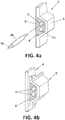
Figure 4 shows a perspective view of the conduit piece (drawing A) and the conduit piece mounted on the spar web (drawing B), according to a preferred embodiment of the present invention. -
Figure 5 shows a schematic perspective view (drawing A) of an HTP equipped with the box structural arrangement of the present invention, and a cross sectional view (drawing B) of the A-A' axis depicted in drawing A. -
Figures 3a and 3b show a box structural arrangement (1) for an aircraft according to a preferred embodiment. According to the invention, the box structural arrangement (1) comprises first (2) and second composite layers (3), at least one spar web (4) transversely arranged between the first (2) and second composite layers (3), and a conduit piece (5) mounted on the at least one spar web (4). - The spar web (4) is extended between opposite edges (2a, 2b, 3a, 3b) of the first and second composite layers (2, 3) following a longitudinal direction. Thus, the spar web (4) has substantially the same length as the first (2) and second composite layers (3) to provide a continuous support to the conduit piece (5).
- The conduit piece (5) is also extended between opposite edges (2a, 2b, 3a, 3b) of the first and second composite layers (2, 3). Thus, the conduit piece (5) has similar (or same) length as the spar web (4) to provide continuous encapsulation (and support) for the pipes or harnesses (19) along the box structural arrangement (1).
- As shown in
Figures 4a and 4b , the hollow section (6) of the conduit piece (5) encloses two conduits (7) (channels or canals) surrounded by a resilient material (8). The conduits (7) are dimensioned to receive pipes or harnesses (19), which will be preferably coated by a hard cover (20) to provide rigidity and an easy insertion into the conduits (7). - Preferably, the conduits (7) may include a foam bed (21) to ease the introduction of pipes or harnesses (19).
- As shown in
Figures 4a and 4b , the conduit piece (5) preferably has an omega cross section with a flat mounting surface (9) to facilitate its coupling to the spar web (4). - Preferably, the resilient material (8) consists of foam or plastic.
- According to another aspect, the invention refers to a horizontal tail plane (10) comprising the box structural arrangement (1) described above.
-
Figures 5a and 5b show a perspective and cross sectional view of a horizontal tail plane (10). The horizontal tail plane (10) has upper (11) and lower skins (12), and forward (13) and rear spars (14) arranged along a spanwise direction. According to the invention, the horizontal tail plane (10) further comprises the box structural arrangement (1) described above, wherein the upper and lower skins (11, 12) comprises the first (2) and second composite layers (3), and wherein at least one conduit piece (5) is mounted on each one of the forward (13) and the rear spars (14). - As shown, the conduit piece (5) and the spar web (4) are preferably extended between the shortest opposite edges of the first and second composite layers (2, 3) following thus a spanwise direction.
- The invention provides an alternative installation concept that offers a clean and smooth surface for aerodynamic purposes. The potential extra weight of the conduit piece till the end of the stabilizer is compensated with the aerodynamic benefit of such a clean surface.
- Similarly, the invention further refers to a wing and a vertical tail plane that comprises a box structural arrangement as described.
- The invention finally refers to a method for manufacturing a box structural arrangement (1) for an aircraft as described above. The method comprises the steps of:
- providing a first and a second layer of composite material (2, 3),
- providing at least one spar web (4) extended between opposite edges (2a, 2b, 3a, 3b) of the first and second composite layers (2, 3),
- arranging the spar web (4) between opposite edges (2a, 2b, 3a, 3b) of the first and second composite layers (2, 3) along a longitudinal direction,
- providing a conduit piece (5) extended between opposite edges (2a, 2b, 3a, 3b) of the first and second composite layers (2, 3) and having a hollow section (6) comprising at least one conduit (7) dimensioned to receive pipes or harnesses and surrounded by a resilient material (8),
- mounting the conduit piece (5) on the spar web (4) to form a channeled box structural arrangement (1).
- The large and single pieces of pipelines/harnesses may be easily installed from one side in the factory. In case of stabilizers (HTP, VTP) connections/bifurcations can be done from outside their boxes, removing then the need for access panels (service doors) in the middle of these components. The potential extra weight is compensated with the cleanness of the surface that leads to aerodynamic benefits.
Claims (8)
- - Box structural arrangement (1) for an aircraft comprising:- a first (2) and second composite layers (3),- at least one spar web (4) extended between opposite edges (2a, 2b, 3a, 3b) of the first and second composite layers (2, 3) along a longitudinal direction, and- a conduit piece (5) having a hollow section (6) comprising at least one conduit (7) dimensioned to receive pipes or harnesses and surrounded by a resilient material (8), the conduit piece (5) extended between opposite edges (2a, 2b, 3a, 3b) of the first and second composite layers (2, 3) and mounted on the spar web (4) to provide a channeled box structural arrangement (1).
- - Box structural arrangement (1) for an aircraft, according to claim 1, wherein the conduit (7) of the conduit piece (5) has a foam bed (21) to ease the introduction of pipes or harnesses (19).
- - Box structural arrangement (1) for an aircraft, according to any preceding claims, wherein the conduit piece (5) has an omega cross section with a flat mounting surface (9).
- - Box structural arrangement for an aircraft, according to any preceding claims, wherein the resilient material (8) consists of foam or plastic.
- - Horizontal tail plane (10) for an aircraft, the horizontal tail plane (10) having upper (11) and lower skins (12), and forward (13) and rear spars (14) arranged along a spanwise direction, the horizontal tail plane (10) further comprising a box structural arrangement (1) according to any of claims 1-4, wherein the upper and lower skins (11, 12) comprises the first (2) and second composite layers (3), and wherein at least one conduit piece (5) is mounted on each one of the forward (13) and the rear spar (14).
- - Wing for an aircraft, the wing having upper and lower skins, and forward and rear spars arranged along a spanwise direction, the wing further comprising a box structural arrangement (1) according to any of claims 1-4, wherein the upper and lower skins comprises the first and second composite layers, and wherein at least one conduit piece is mounted on each one of the forward and the rear spar.
- - Vertical tail plane for an aircraft, the vertical tail plane having upper and lower skins, and forward and rear spars arranged along a spanwise direction, the vertical tail plane further comprising a box structural arrangement (1) according to any of claims 1-4, wherein the upper and lower skins comprises the first and second composite layers, and wherein the at least one conduit piece is mounted on each one of the forward and the rear spar.
- - Method for manufacturing a box structural arrangement (1) for an aircraft, comprising the steps of:providing a first and a second layer of composite material (2, 3),providing at least one spar web (4) extended between opposite edges (2a, 2b, 3a, 3b) of the first and second composite layers (2, 3),arranging the spar web (4) between opposite edges (2a, 2b, 3a, 3b) of the first and second composite layers (2, 3) along a longitudinal direction,providing a conduit piece (5) extended between opposite edges (2a, 2b, 3a, 3b) of the first and second composite layers (2, 3) and having a hollow section (6) comprising at least one conduit (7) dimensioned to receive pipes or harnesses and surrounded by a resilient material (8),mounting the conduit piece (5) on the spar web (4) to form a channeled box structural arrangement (1).
Priority Applications (3)
| Application Number | Priority Date | Filing Date | Title |
|---|---|---|---|
| EP17382460.8A EP3428056B1 (en) | 2017-07-13 | 2017-07-13 | Box structural arrangenment for an aircraft and manufacturing method thereof |
| ES17382460T ES2800182T3 (en) | 2017-07-13 | 2017-07-13 | Structural arrangement of the box for an aircraft and its manufacturing process |
| US16/032,246 US10906628B2 (en) | 2017-07-13 | 2018-07-11 | Box structural arrangement for an aircraft and manufacturing method thereof |
Applications Claiming Priority (1)
| Application Number | Priority Date | Filing Date | Title |
|---|---|---|---|
| EP17382460.8A EP3428056B1 (en) | 2017-07-13 | 2017-07-13 | Box structural arrangenment for an aircraft and manufacturing method thereof |
Publications (2)
| Publication Number | Publication Date |
|---|---|
| EP3428056A1 true EP3428056A1 (en) | 2019-01-16 |
| EP3428056B1 EP3428056B1 (en) | 2020-03-25 |
Family
ID=59520839
Family Applications (1)
| Application Number | Title | Priority Date | Filing Date |
|---|---|---|---|
| EP17382460.8A Active EP3428056B1 (en) | 2017-07-13 | 2017-07-13 | Box structural arrangenment for an aircraft and manufacturing method thereof |
Country Status (3)
| Country | Link |
|---|---|
| US (1) | US10906628B2 (en) |
| EP (1) | EP3428056B1 (en) |
| ES (1) | ES2800182T3 (en) |
Cited By (3)
| Publication number | Priority date | Publication date | Assignee | Title |
|---|---|---|---|---|
| CN112249300A (en) * | 2020-10-22 | 2021-01-22 | 航天特种材料及工艺技术研究所 | Carbon fiber composite material airfoil leading edge structure |
| EP4059834A1 (en) * | 2021-03-17 | 2022-09-21 | The Boeing Company | Electrical pass-through assembly for traversing a structure |
| EP3738753B1 (en) * | 2019-05-14 | 2023-06-07 | Cetex Institut gGmbH | Method and device for producing hybrid fibre bundle |
Families Citing this family (3)
| Publication number | Priority date | Publication date | Assignee | Title |
|---|---|---|---|---|
| ES2800182T3 (en) * | 2017-07-13 | 2020-12-28 | Airbus Operations Sl | Structural arrangement of the box for an aircraft and its manufacturing process |
| EP3486074B1 (en) * | 2017-11-15 | 2024-04-03 | Airbus Operations S.L. | Composite structure having an integrated support, attachable system comprising the composite structure, and method for manufacturing said composite structure |
| DE102022116949A1 (en) * | 2022-07-07 | 2024-01-18 | Airbus Operations Gmbh | Wing for an aircraft |
Citations (7)
| Publication number | Priority date | Publication date | Assignee | Title |
|---|---|---|---|---|
| GB1097481A (en) * | 1964-01-05 | 1968-01-03 | Lawrence Patrick Moore | Improvements in or relating to the manufacture of aircraft wings and the like |
| US5332178A (en) * | 1992-06-05 | 1994-07-26 | Williams International Corporation | Composite wing and manufacturing process thereof |
| US20090218450A1 (en) * | 2008-02-29 | 2009-09-03 | Airbus Uk Limited | Fitting for pivotally connecting aerodynamic control element to aircraft structure |
| US20100065687A1 (en) * | 2008-04-02 | 2010-03-18 | Airbus Uk Limited | Aircraft structure |
| WO2010116170A2 (en) * | 2009-04-09 | 2010-10-14 | Airbus Operations Limited | Improved wing structure |
| EP2735503A2 (en) * | 2012-11-21 | 2014-05-28 | Airbus Operations Limited | Modular structural assembly |
| US20160129985A1 (en) * | 2014-11-08 | 2016-05-12 | Airbus Group India Private Limited | Aircraft structure having cables located in stringers |
Family Cites Families (27)
| Publication number | Priority date | Publication date | Assignee | Title |
|---|---|---|---|---|
| US2443323A (en) * | 1944-05-10 | 1948-06-15 | Universal Moulded Products Cor | Airplane control surface |
| US3907442A (en) * | 1972-11-01 | 1975-09-23 | Briles Manufacturing Omark Ind | Fastener sealant injection system |
| FR2381662A1 (en) * | 1977-02-28 | 1978-09-22 | Aerospatiale | BLADE, ESPECIALLY FOR A HELICOPTER ROTOR, AND ITS MANUFACTURING PROCESS |
| US4219980A (en) * | 1977-08-26 | 1980-09-02 | Rockwell International Corporation | Reinforced composite structure and method of fabrication thereof |
| US4331495A (en) * | 1978-01-19 | 1982-05-25 | Rockwell International Corporation | Method of fabricating a reinforced composite structure |
| US4256790A (en) * | 1978-01-19 | 1981-03-17 | Rockwell International Corporation | Reinforced composite structure and method of fabrication thereof |
| AT398064B (en) * | 1992-07-01 | 1994-09-26 | Hoac Austria Flugzeugwerk Wr N | PLASTIC COMPOSITE PROFILE, ESPECIALLY WING SLEEVE FOR AIRCRAFT CONSTRUCTION |
| US5833786A (en) * | 1996-05-16 | 1998-11-10 | The Boeing Company | Titanium radius filler for use in composite interfaces |
| US6190484B1 (en) * | 1999-02-19 | 2001-02-20 | Kari Appa | Monolithic composite wing manufacturing process |
| US6116539A (en) * | 1999-03-19 | 2000-09-12 | Williams International Co. L.L.C. | Aeroelastically stable forward swept wing |
| CN1489637A (en) * | 2000-12-21 | 2004-04-14 | �Ƹ��� | Aluminum alloy products and artificial aging method |
| US6638466B1 (en) * | 2000-12-28 | 2003-10-28 | Raytheon Aircraft Company | Methods of manufacturing separable structures |
| US7052572B2 (en) * | 2001-08-01 | 2006-05-30 | Fuji Jukogyo Kabushiki Kaisha | Method for manufacturing a structure |
| JP2004025946A (en) * | 2002-06-24 | 2004-01-29 | Honda Motor Co Ltd | Wing structure of aircraft |
| US7249943B2 (en) * | 2003-08-01 | 2007-07-31 | Alliant Techsystems Inc. | Apparatus for forming composite stiffeners and reinforcing structures |
| US7264200B2 (en) * | 2004-07-23 | 2007-09-04 | The Boeing Company | System and method for improved rotor tip performance |
| DE502005001475D1 (en) * | 2004-12-22 | 2007-10-25 | Airbus Deutschland Gmbh Hrb 43527 | Structure of an aerodynamic effective surface of an aircraft |
| US7686905B2 (en) * | 2005-09-06 | 2010-03-30 | The Boeing Company | Copper grid repair technique for lightning strike protection |
| FI119726B (en) * | 2006-09-26 | 2009-02-27 | Patria Aerostructures Oy | Aircraft arch element, wing, control surface and stabilizer |
| EP1946913B1 (en) * | 2007-01-22 | 2011-03-16 | Saab Ab | Method and apparatus for manufacturing a wing spar profile element |
| US7905706B1 (en) * | 2007-12-21 | 2011-03-15 | Florida Turbine Technologies, Inc. | Turbine blade with spar and shell cooling |
| US8165703B2 (en) * | 2008-08-18 | 2012-04-24 | Airbus Operations S.L. | Computer assisted method for the advanced design of bent parts of composite material |
| US7901184B2 (en) * | 2009-06-16 | 2011-03-08 | General Electric Company | Torsionally loadable wind turbine blade |
| FR2981880B1 (en) * | 2011-10-28 | 2014-09-19 | Daher Aerospace | PROCESS FOR SEALING A FUEL TANK |
| US10556665B2 (en) * | 2016-06-20 | 2020-02-11 | The Boeing Company | Apparatuses and methods for improved sealing |
| ES2764122T3 (en) * | 2016-12-02 | 2020-06-02 | Airbus Operations Sl | Integration of the leading edge of an aircraft stabilizer with the torsion box and the fuselage |
| ES2800182T3 (en) * | 2017-07-13 | 2020-12-28 | Airbus Operations Sl | Structural arrangement of the box for an aircraft and its manufacturing process |
-
2017
- 2017-07-13 ES ES17382460T patent/ES2800182T3/en active Active
- 2017-07-13 EP EP17382460.8A patent/EP3428056B1/en active Active
-
2018
- 2018-07-11 US US16/032,246 patent/US10906628B2/en active Active
Patent Citations (7)
| Publication number | Priority date | Publication date | Assignee | Title |
|---|---|---|---|---|
| GB1097481A (en) * | 1964-01-05 | 1968-01-03 | Lawrence Patrick Moore | Improvements in or relating to the manufacture of aircraft wings and the like |
| US5332178A (en) * | 1992-06-05 | 1994-07-26 | Williams International Corporation | Composite wing and manufacturing process thereof |
| US20090218450A1 (en) * | 2008-02-29 | 2009-09-03 | Airbus Uk Limited | Fitting for pivotally connecting aerodynamic control element to aircraft structure |
| US20100065687A1 (en) * | 2008-04-02 | 2010-03-18 | Airbus Uk Limited | Aircraft structure |
| WO2010116170A2 (en) * | 2009-04-09 | 2010-10-14 | Airbus Operations Limited | Improved wing structure |
| EP2735503A2 (en) * | 2012-11-21 | 2014-05-28 | Airbus Operations Limited | Modular structural assembly |
| US20160129985A1 (en) * | 2014-11-08 | 2016-05-12 | Airbus Group India Private Limited | Aircraft structure having cables located in stringers |
Cited By (4)
| Publication number | Priority date | Publication date | Assignee | Title |
|---|---|---|---|---|
| EP3738753B1 (en) * | 2019-05-14 | 2023-06-07 | Cetex Institut gGmbH | Method and device for producing hybrid fibre bundle |
| CN112249300A (en) * | 2020-10-22 | 2021-01-22 | 航天特种材料及工艺技术研究所 | Carbon fiber composite material airfoil leading edge structure |
| CN112249300B (en) * | 2020-10-22 | 2022-02-15 | 航天特种材料及工艺技术研究所 | Carbon fiber composite material airfoil leading edge structure |
| EP4059834A1 (en) * | 2021-03-17 | 2022-09-21 | The Boeing Company | Electrical pass-through assembly for traversing a structure |
Also Published As
| Publication number | Publication date |
|---|---|
| US10906628B2 (en) | 2021-02-02 |
| ES2800182T3 (en) | 2020-12-28 |
| US20190016437A1 (en) | 2019-01-17 |
| EP3428056B1 (en) | 2020-03-25 |
Similar Documents
| Publication | Publication Date | Title |
|---|---|---|
| EP3428056B1 (en) | Box structural arrangenment for an aircraft and manufacturing method thereof | |
| US8528859B2 (en) | Installation system for an airplane | |
| US8657232B2 (en) | Fuselage structure for combined fixing of insulation blankets and items of equipment, aircraft incorporating such a structure | |
| CN102862673B (en) | Be used for the medial support structures of the driving cabin of airborne vehicle | |
| US20210046725A1 (en) | Core material for composite structures | |
| US20110036942A1 (en) | Engine attachment pylon comprising means of fastening spars and panels located outside the inner space in the box | |
| CN102015442A (en) | Method for attaching an aircraft floor module | |
| US8616501B2 (en) | Pre-installed adaptable supply network for aeroplanes | |
| EP3505441A1 (en) | A leading edge structure for a flow control system of an aircraft | |
| US8382034B2 (en) | System box for accommodating aircraft systems | |
| JP2012522677A (en) | Body segment and method for manufacturing body segment | |
| EP2605959A1 (en) | Multi-spar port box joint | |
| CN103303484A (en) | Engine mounting system for an aircraft | |
| US20190112035A1 (en) | Landing gear bay roof comprising at least one gantry installed against a lower face of its wall | |
| US20100320324A1 (en) | Fuselage structure for aircraft | |
| CN103832578A (en) | Modular structural assembly | |
| EP3090940B1 (en) | Horizontal tail plane with a multi-rib torsion box | |
| EP3124375B1 (en) | Panel member | |
| US20220018328A1 (en) | Rotor blade of a wind turbine, comprising an insulator layer and a protective layer | |
| CN108238261B (en) | Main structure for a support for an aircraft propeller group comprising a pyramidal section with convergent struts | |
| BR112013032732B1 (en) | METHOD FOR FITTING A FLYING VEHICLE FAIRING AND FLIGHTING A FLOORING FAIR | |
| EP2581205A1 (en) | Component for connecting structures and method of producing it | |
| EP3388339A1 (en) | Duct assembly and method of assembling thereof | |
| US20220194548A1 (en) | Aircraft structure | |
| US8348197B2 (en) | Integration system for lifting surface lateral parts in an aircraft |
Legal Events
| Date | Code | Title | Description |
|---|---|---|---|
| PUAI | Public reference made under article 153(3) epc to a published international application that has entered the european phase |
Free format text: ORIGINAL CODE: 0009012 |
|
| STAA | Information on the status of an ep patent application or granted ep patent |
Free format text: STATUS: THE APPLICATION HAS BEEN PUBLISHED |
|
| AK | Designated contracting states |
Kind code of ref document: A1 Designated state(s): AL AT BE BG CH CY CZ DE DK EE ES FI FR GB GR HR HU IE IS IT LI LT LU LV MC MK MT NL NO PL PT RO RS SE SI SK SM TR |
|
| AX | Request for extension of the european patent |
Extension state: BA ME |
|
| STAA | Information on the status of an ep patent application or granted ep patent |
Free format text: STATUS: REQUEST FOR EXAMINATION WAS MADE |
|
| 17P | Request for examination filed |
Effective date: 20190701 |
|
| RBV | Designated contracting states (corrected) |
Designated state(s): AL AT BE BG CH CY CZ DE DK EE ES FI FR GB GR HR HU IE IS IT LI LT LU LV MC MK MT NL NO PL PT RO RS SE SI SK SM TR |
|
| REG | Reference to a national code |
Ref country code: DE Ref legal event code: R079 Ref document number: 602017013579 Country of ref document: DE Free format text: PREVIOUS MAIN CLASS: B64C0001060000 Ipc: B64C0003200000 |
|
| RIC1 | Information provided on ipc code assigned before grant |
Ipc: B64C 3/26 20060101ALN20191104BHEP Ipc: B64C 5/02 20060101ALN20191104BHEP Ipc: B64C 5/06 20060101ALN20191104BHEP Ipc: B64C 1/06 20060101ALN20191104BHEP Ipc: B64C 3/20 20060101AFI20191104BHEP Ipc: B64C 3/18 20060101ALN20191104BHEP Ipc: B64C 1/00 20060101ALN20191104BHEP |
|
| GRAP | Despatch of communication of intention to grant a patent |
Free format text: ORIGINAL CODE: EPIDOSNIGR1 |
|
| STAA | Information on the status of an ep patent application or granted ep patent |
Free format text: STATUS: GRANT OF PATENT IS INTENDED |
|
| INTG | Intention to grant announced |
Effective date: 20191218 |
|
| RIC1 | Information provided on ipc code assigned before grant |
Ipc: B64C 3/20 20060101AFI20191206BHEP Ipc: B64C 1/00 20060101ALN20191206BHEP Ipc: B64C 3/18 20060101ALN20191206BHEP Ipc: B64C 5/06 20060101ALN20191206BHEP Ipc: B64C 1/06 20060101ALN20191206BHEP Ipc: B64C 3/26 20060101ALN20191206BHEP Ipc: B64C 5/02 20060101ALN20191206BHEP |
|
| RIN1 | Information on inventor provided before grant (corrected) |
Inventor name: RODRIGUEZ URBINA, LUIS MANUEL Inventor name: ARANA HIDALGO, ALBERTO |
|
| GRAS | Grant fee paid |
Free format text: ORIGINAL CODE: EPIDOSNIGR3 |
|
| GRAA | (expected) grant |
Free format text: ORIGINAL CODE: 0009210 |
|
| STAA | Information on the status of an ep patent application or granted ep patent |
Free format text: STATUS: THE PATENT HAS BEEN GRANTED |
|
| AK | Designated contracting states |
Kind code of ref document: B1 Designated state(s): AL AT BE BG CH CY CZ DE DK EE ES FI FR GB GR HR HU IE IS IT LI LT LU LV MC MK MT NL NO PL PT RO RS SE SI SK SM TR |
|
| REG | Reference to a national code |
Ref country code: GB Ref legal event code: FG4D |
|
| REG | Reference to a national code |
Ref country code: AT Ref legal event code: REF Ref document number: 1248279 Country of ref document: AT Kind code of ref document: T Effective date: 20200415 Ref country code: IE Ref legal event code: FG4D |
|
| REG | Reference to a national code |
Ref country code: DE Ref legal event code: R096 Ref document number: 602017013579 Country of ref document: DE |
|
| PG25 | Lapsed in a contracting state [announced via postgrant information from national office to epo] |
Ref country code: NO Free format text: LAPSE BECAUSE OF FAILURE TO SUBMIT A TRANSLATION OF THE DESCRIPTION OR TO PAY THE FEE WITHIN THE PRESCRIBED TIME-LIMIT Effective date: 20200625 Ref country code: FI Free format text: LAPSE BECAUSE OF FAILURE TO SUBMIT A TRANSLATION OF THE DESCRIPTION OR TO PAY THE FEE WITHIN THE PRESCRIBED TIME-LIMIT Effective date: 20200325 Ref country code: RS Free format text: LAPSE BECAUSE OF FAILURE TO SUBMIT A TRANSLATION OF THE DESCRIPTION OR TO PAY THE FEE WITHIN THE PRESCRIBED TIME-LIMIT Effective date: 20200325 |
|
| PG25 | Lapsed in a contracting state [announced via postgrant information from national office to epo] |
Ref country code: SE Free format text: LAPSE BECAUSE OF FAILURE TO SUBMIT A TRANSLATION OF THE DESCRIPTION OR TO PAY THE FEE WITHIN THE PRESCRIBED TIME-LIMIT Effective date: 20200325 Ref country code: LV Free format text: LAPSE BECAUSE OF FAILURE TO SUBMIT A TRANSLATION OF THE DESCRIPTION OR TO PAY THE FEE WITHIN THE PRESCRIBED TIME-LIMIT Effective date: 20200325 Ref country code: HR Free format text: LAPSE BECAUSE OF FAILURE TO SUBMIT A TRANSLATION OF THE DESCRIPTION OR TO PAY THE FEE WITHIN THE PRESCRIBED TIME-LIMIT Effective date: 20200325 Ref country code: GR Free format text: LAPSE BECAUSE OF FAILURE TO SUBMIT A TRANSLATION OF THE DESCRIPTION OR TO PAY THE FEE WITHIN THE PRESCRIBED TIME-LIMIT Effective date: 20200626 Ref country code: BG Free format text: LAPSE BECAUSE OF FAILURE TO SUBMIT A TRANSLATION OF THE DESCRIPTION OR TO PAY THE FEE WITHIN THE PRESCRIBED TIME-LIMIT Effective date: 20200625 |
|
| REG | Reference to a national code |
Ref country code: NL Ref legal event code: MP Effective date: 20200325 |
|
| REG | Reference to a national code |
Ref country code: LT Ref legal event code: MG4D |
|
| PG25 | Lapsed in a contracting state [announced via postgrant information from national office to epo] |
Ref country code: NL Free format text: LAPSE BECAUSE OF FAILURE TO SUBMIT A TRANSLATION OF THE DESCRIPTION OR TO PAY THE FEE WITHIN THE PRESCRIBED TIME-LIMIT Effective date: 20200325 |
|
| PG25 | Lapsed in a contracting state [announced via postgrant information from national office to epo] |
Ref country code: SK Free format text: LAPSE BECAUSE OF FAILURE TO SUBMIT A TRANSLATION OF THE DESCRIPTION OR TO PAY THE FEE WITHIN THE PRESCRIBED TIME-LIMIT Effective date: 20200325 Ref country code: SM Free format text: LAPSE BECAUSE OF FAILURE TO SUBMIT A TRANSLATION OF THE DESCRIPTION OR TO PAY THE FEE WITHIN THE PRESCRIBED TIME-LIMIT Effective date: 20200325 Ref country code: LT Free format text: LAPSE BECAUSE OF FAILURE TO SUBMIT A TRANSLATION OF THE DESCRIPTION OR TO PAY THE FEE WITHIN THE PRESCRIBED TIME-LIMIT Effective date: 20200325 Ref country code: EE Free format text: LAPSE BECAUSE OF FAILURE TO SUBMIT A TRANSLATION OF THE DESCRIPTION OR TO PAY THE FEE WITHIN THE PRESCRIBED TIME-LIMIT Effective date: 20200325 Ref country code: CZ Free format text: LAPSE BECAUSE OF FAILURE TO SUBMIT A TRANSLATION OF THE DESCRIPTION OR TO PAY THE FEE WITHIN THE PRESCRIBED TIME-LIMIT Effective date: 20200325 Ref country code: RO Free format text: LAPSE BECAUSE OF FAILURE TO SUBMIT A TRANSLATION OF THE DESCRIPTION OR TO PAY THE FEE WITHIN THE PRESCRIBED TIME-LIMIT Effective date: 20200325 Ref country code: PT Free format text: LAPSE BECAUSE OF FAILURE TO SUBMIT A TRANSLATION OF THE DESCRIPTION OR TO PAY THE FEE WITHIN THE PRESCRIBED TIME-LIMIT Effective date: 20200818 Ref country code: IS Free format text: LAPSE BECAUSE OF FAILURE TO SUBMIT A TRANSLATION OF THE DESCRIPTION OR TO PAY THE FEE WITHIN THE PRESCRIBED TIME-LIMIT Effective date: 20200725 |
|
| REG | Reference to a national code |
Ref country code: AT Ref legal event code: MK05 Ref document number: 1248279 Country of ref document: AT Kind code of ref document: T Effective date: 20200325 |
|
| REG | Reference to a national code |
Ref country code: DE Ref legal event code: R097 Ref document number: 602017013579 Country of ref document: DE |
|
| PG25 | Lapsed in a contracting state [announced via postgrant information from national office to epo] |
Ref country code: AT Free format text: LAPSE BECAUSE OF FAILURE TO SUBMIT A TRANSLATION OF THE DESCRIPTION OR TO PAY THE FEE WITHIN THE PRESCRIBED TIME-LIMIT Effective date: 20200325 Ref country code: IT Free format text: LAPSE BECAUSE OF FAILURE TO SUBMIT A TRANSLATION OF THE DESCRIPTION OR TO PAY THE FEE WITHIN THE PRESCRIBED TIME-LIMIT Effective date: 20200325 Ref country code: DK Free format text: LAPSE BECAUSE OF FAILURE TO SUBMIT A TRANSLATION OF THE DESCRIPTION OR TO PAY THE FEE WITHIN THE PRESCRIBED TIME-LIMIT Effective date: 20200325 |
|
| PLBE | No opposition filed within time limit |
Free format text: ORIGINAL CODE: 0009261 |
|
| STAA | Information on the status of an ep patent application or granted ep patent |
Free format text: STATUS: NO OPPOSITION FILED WITHIN TIME LIMIT |
|
| PG25 | Lapsed in a contracting state [announced via postgrant information from national office to epo] |
Ref country code: MC Free format text: LAPSE BECAUSE OF FAILURE TO SUBMIT A TRANSLATION OF THE DESCRIPTION OR TO PAY THE FEE WITHIN THE PRESCRIBED TIME-LIMIT Effective date: 20200325 Ref country code: PL Free format text: LAPSE BECAUSE OF FAILURE TO SUBMIT A TRANSLATION OF THE DESCRIPTION OR TO PAY THE FEE WITHIN THE PRESCRIBED TIME-LIMIT Effective date: 20200325 |
|
| REG | Reference to a national code |
Ref country code: CH Ref legal event code: PL |
|
| 26N | No opposition filed |
Effective date: 20210112 |
|
| REG | Reference to a national code |
Ref country code: BE Ref legal event code: MM Effective date: 20200731 |
|
| PG25 | Lapsed in a contracting state [announced via postgrant information from national office to epo] |
Ref country code: LI Free format text: LAPSE BECAUSE OF NON-PAYMENT OF DUE FEES Effective date: 20200731 Ref country code: LU Free format text: LAPSE BECAUSE OF NON-PAYMENT OF DUE FEES Effective date: 20200713 Ref country code: CH Free format text: LAPSE BECAUSE OF NON-PAYMENT OF DUE FEES Effective date: 20200731 |
|
| PG25 | Lapsed in a contracting state [announced via postgrant information from national office to epo] |
Ref country code: BE Free format text: LAPSE BECAUSE OF NON-PAYMENT OF DUE FEES Effective date: 20200731 Ref country code: SI Free format text: LAPSE BECAUSE OF FAILURE TO SUBMIT A TRANSLATION OF THE DESCRIPTION OR TO PAY THE FEE WITHIN THE PRESCRIBED TIME-LIMIT Effective date: 20200325 |
|
| PG25 | Lapsed in a contracting state [announced via postgrant information from national office to epo] |
Ref country code: IE Free format text: LAPSE BECAUSE OF NON-PAYMENT OF DUE FEES Effective date: 20200713 |
|
| PG25 | Lapsed in a contracting state [announced via postgrant information from national office to epo] |
Ref country code: TR Free format text: LAPSE BECAUSE OF FAILURE TO SUBMIT A TRANSLATION OF THE DESCRIPTION OR TO PAY THE FEE WITHIN THE PRESCRIBED TIME-LIMIT Effective date: 20200325 Ref country code: MT Free format text: LAPSE BECAUSE OF FAILURE TO SUBMIT A TRANSLATION OF THE DESCRIPTION OR TO PAY THE FEE WITHIN THE PRESCRIBED TIME-LIMIT Effective date: 20200325 Ref country code: CY Free format text: LAPSE BECAUSE OF FAILURE TO SUBMIT A TRANSLATION OF THE DESCRIPTION OR TO PAY THE FEE WITHIN THE PRESCRIBED TIME-LIMIT Effective date: 20200325 |
|
| PG25 | Lapsed in a contracting state [announced via postgrant information from national office to epo] |
Ref country code: MK Free format text: LAPSE BECAUSE OF FAILURE TO SUBMIT A TRANSLATION OF THE DESCRIPTION OR TO PAY THE FEE WITHIN THE PRESCRIBED TIME-LIMIT Effective date: 20200325 Ref country code: AL Free format text: LAPSE BECAUSE OF FAILURE TO SUBMIT A TRANSLATION OF THE DESCRIPTION OR TO PAY THE FEE WITHIN THE PRESCRIBED TIME-LIMIT Effective date: 20200325 |
|
| PGFP | Annual fee paid to national office [announced via postgrant information from national office to epo] |
Ref country code: GB Payment date: 20230721 Year of fee payment: 7 Ref country code: ES Payment date: 20230926 Year of fee payment: 7 |
|
| PGFP | Annual fee paid to national office [announced via postgrant information from national office to epo] |
Ref country code: FR Payment date: 20230726 Year of fee payment: 7 Ref country code: DE Payment date: 20230719 Year of fee payment: 7 |