EP3428009A1 - Fahrzeugsitz mit einstellbarem dämpfer - Google Patents
Fahrzeugsitz mit einstellbarem dämpfer Download PDFInfo
- Publication number
- EP3428009A1 EP3428009A1 EP18181430.2A EP18181430A EP3428009A1 EP 3428009 A1 EP3428009 A1 EP 3428009A1 EP 18181430 A EP18181430 A EP 18181430A EP 3428009 A1 EP3428009 A1 EP 3428009A1
- Authority
- EP
- European Patent Office
- Prior art keywords
- rotation
- vehicle seat
- axis
- scissor arm
- damper
- Prior art date
- Legal status (The legal status is an assumption and is not a legal conclusion. Google has not performed a legal analysis and makes no representation as to the accuracy of the status listed.)
- Granted
Links
Images



Classifications
-
- B—PERFORMING OPERATIONS; TRANSPORTING
- B60—VEHICLES IN GENERAL
- B60N—SEATS SPECIALLY ADAPTED FOR VEHICLES; VEHICLE PASSENGER ACCOMMODATION NOT OTHERWISE PROVIDED FOR
- B60N2/00—Seats specially adapted for vehicles; Arrangement or mounting of seats in vehicles
- B60N2/50—Seat suspension devices
- B60N2/52—Seat suspension devices using fluid means
- B60N2/522—Seat suspension devices using fluid means characterised by dampening means
-
- B—PERFORMING OPERATIONS; TRANSPORTING
- B60—VEHICLES IN GENERAL
- B60N—SEATS SPECIALLY ADAPTED FOR VEHICLES; VEHICLE PASSENGER ACCOMMODATION NOT OTHERWISE PROVIDED FOR
- B60N2/00—Seats specially adapted for vehicles; Arrangement or mounting of seats in vehicles
- B60N2/50—Seat suspension devices
- B60N2/502—Seat suspension devices attached to the base of the seat
-
- B—PERFORMING OPERATIONS; TRANSPORTING
- B60—VEHICLES IN GENERAL
- B60N—SEATS SPECIALLY ADAPTED FOR VEHICLES; VEHICLE PASSENGER ACCOMMODATION NOT OTHERWISE PROVIDED FOR
- B60N2/00—Seats specially adapted for vehicles; Arrangement or mounting of seats in vehicles
- B60N2/50—Seat suspension devices
- B60N2/506—Seat guided by rods
- B60N2/508—Scissors-like structure
-
- B—PERFORMING OPERATIONS; TRANSPORTING
- B60—VEHICLES IN GENERAL
- B60N—SEATS SPECIALLY ADAPTED FOR VEHICLES; VEHICLE PASSENGER ACCOMMODATION NOT OTHERWISE PROVIDED FOR
- B60N2/00—Seats specially adapted for vehicles; Arrangement or mounting of seats in vehicles
- B60N2/50—Seat suspension devices
- B60N2/52—Seat suspension devices using fluid means
- B60N2/525—Seat suspension devices using fluid means using gas
-
- B—PERFORMING OPERATIONS; TRANSPORTING
- B60—VEHICLES IN GENERAL
- B60N—SEATS SPECIALLY ADAPTED FOR VEHICLES; VEHICLE PASSENGER ACCOMMODATION NOT OTHERWISE PROVIDED FOR
- B60N2/00—Seats specially adapted for vehicles; Arrangement or mounting of seats in vehicles
- B60N2/02—Seats specially adapted for vehicles; Arrangement or mounting of seats in vehicles the seat or part thereof being movable, e.g. adjustable
- B60N2/04—Seats specially adapted for vehicles; Arrangement or mounting of seats in vehicles the seat or part thereof being movable, e.g. adjustable the whole seat being movable
- B60N2/16—Seats specially adapted for vehicles; Arrangement or mounting of seats in vehicles the seat or part thereof being movable, e.g. adjustable the whole seat being movable height-adjustable
Definitions
- the invention relates to a vehicle seat having a seat top and a seat bottom, wherein the seat top and the seat bottom are connected by a scissor frame, and with a damper, wherein the scissors-type frame has a first scissor arm and a second scissor arm, wherein the first scissor arm and the second scissor arm rotatable are mounted about a common axis of rotation, wherein a first end of the damper is rotatably connected to the first scissor arm.
- Such vehicle seats are attenuated in its deflection movement, which is guided by the scissors frame, by means of a damper and thereby reduces vibration loads on the driver who has taken place on such a vehicle seat.
- the central idea of the invention is to provide a vehicle seat with a seat top and a seat bottom, wherein the seat top and the seat bottom are connected by a scissor frame, and with a damper, wherein the scissors-type frame has a first scissor arm and a second scissor arm, wherein the first scissor arm and the second scissor arm are rotatably mounted about a common axis of rotation, wherein a first end of the damper is rotatably connected to the first scissor arm, wherein a first lever member and a second lever member are provided, wherein a first end of the first lever member is rotatably connected to the first scissor arm and a first end of the second lever member is rotatably connected to the second scissor arm and a second end of the damper is rotatably connected to both a second end of the first lever member and a second end of the second lever member.
- the vehicle seat can be used for land vehicles, commercial vehicles, agricultural vehicles, construction vehicles, other trucks and cars as well as for boats and ships.
- the first end of the first lever element by means of a first axis of rotation with the first scissor arm and the first end of the second lever element by means of a second axis of rotation rotatably connected to the second scissor arm and the second end of the first lever element, the second end of the second lever element and the second end of the damper connected by a third pivot axis.
- first end of the first lever element is connected by means of the first axis of rotation directly to the first scissor arm and the first end of the second lever element by means of the second axis of rotation directly to the second scissor arm.
- first axis of rotation directly to the first scissor arm
- second axis of rotation directly to the second scissor arm.
- first axis of rotation, the second axis of rotation and the third axis of rotation are arranged in pairs parallel to one another.
- first, second and third axes of rotation and the common axis of rotation extend in a vehicle seat width direction of the vehicle seat.
- a first connecting line between the first pivot axis and the third pivot axis and a second connecting line between the second pivot axis and the third pivot axis form an acute angle Angle is preferably between 5 ° and 45 °, and wherein the angle is preferably less than 10 °, more preferably less than 5 ° and particularly preferably less than 3 °.
- Fully Sprung means hereby that a distance between the seat shell and the seat bottom is minimal, so the scissor frame is folded up to the maximum.
- maximum compression may also be used.
- Such a configuration is useful to avoid possible dead points in the movement of the first lever member, the second lever member and corresponding to the second end of the damper.
- a first connection line between the first pivot axis and the third pivot axis and a second connection line between the second pivot axis and the third pivot axis either one include an obtuse angle, wherein the angle is preferably greater than 170 ° and more preferably greater than 175 °, or include an angle of 180 °.
- the angle can be 180 °, since due to the gravitational force no dead center can occur and thus a movement of the seat upper part relative to the seat bottom is possible.
- the first lever element is formed in at least one direction perpendicular to the first axis of rotation U-shaped with a first leg and a second leg, wherein the first leg rotatably connected to the first lever member and the second leg to the third axis of rotation is.
- first leg and the second leg extend in the direction of the connecting line from the first axis of rotation and the third axis of rotation.
- the direction perpendicular to the first axis of rotation may in particular be perpendicular to the connecting line.
- the second leg extends in the direction of the connecting line farther than the first leg.
- the second lever element is plate-like.
- the second end of the second lever element is arranged in the longitudinal direction of extension of the third axis of rotation between the first leg and the second leg.
- a proposed according to a preferred embodiment of the embodiment of the scissor frame is such that the first scissor arm and the second scissor arm each have a movable bearing and a fixed bearing, wherein the bearing of the first scissor arm with the seat shell and the bearing of the second scissor arm are connected to the seat bottom.
- the first end of the damper is connected to the movable bearing of the first scissor arm. That is, in a deflection of the scissors-type frame, the first end of the damper follows in accordance with the movement of the first scissor arm.
- a distance of the first axis of rotation to the common axis of rotation is less than a distance of the first axis of rotation to the movable bearing of the first scissor arm, and wherein a distance of the second axis of rotation to the common axis of rotation is less than a distance of the second axis of rotation to the Floating bearing of the second scissor arm.
- the distance of the first axis of rotation to the third axis of rotation and the distance of the second axis of rotation to the third axis of rotation are substantially equal. It is also conceivable that the distance between the first axis of rotation to the common axis of rotation and the distance of the second axis of rotation to the common axis of rotation are also formed substantially the same.
- the damper rate can be adjusted.
- the damper rate may be such that in a normal mode a soft damper characteristic prevails and at a deflection in the direction of the maximum deflection of the vehicle seat by changing the second end of the damper relative to the first end of the damper, the damper rate is adjusted ,
- the ratio of the distance change seat shell to seat bottom and length change of the damper can be designed such that a deflection of or in the first state, a ratio of change in distance seat top to seat bottom to change in length of the damper element ⁇ 1, and a deflection or a ratio of change in the distance seat top to seat base to change in length of the damper element is also ⁇ 1 or in the second state.
- a third state ie the normal operation or normal state, in which preferably the damping path in the vehicle seat height direction is substantially equal up and down, the ratio of change in distance seat top to seat bottom to length change of the damper element >> 1, so extremely large, ideally infinity.
- a relatively large deflection of the vehicle seat causes only a small change in length of the damper. Accordingly, the damping force changes only slightly or to a small extent.
- the vehicle seat additionally comprises an air spring for springs of the vehicle seat, wherein the air spring is connected on the one hand to the scissor frame and on the other hand to the seat shell or the seat base.
- a utility vehicle comprising a vehicle seat according to one of the described embodiments.
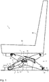
- a vehicle seat 1 is shown according to a particularly preferred embodiment, wherein the vehicle seat 1 has a seat top 2 and a seat bottom 3, wherein the seat top 2, a seat part 32 and a backrest 33 may be arranged.
- the seat bottom 3, however, is preferably connected to a body floor 34 or the like.
- the seat upper part 2 and the seat bottom 3 are further connected to each other by means of a scissors-type frame 4, the scissors-type frame 4 having at least one first scissor arm 6 and at least one second scissor arm 7, wherein the first scissor arm 6 and the second scissor arm 7 by means of a common axis of rotation 8 are rotatably connected.
- the first scissor arm 6 is in particular rotatably connected by means of a fixed bearing 29 with the seat upper part 2, whereas the second scissor arm 7 is connected in particular rotatably by means of a fixed bearing 29 with the seat bottom 3.
- Each scissor arm also has in each case a movable bearing 28, which is connected to the respective other vehicle seat part, for example, for the first scissor arm 6, the floating bearing is connected to the seat bottom 3, in particular slidably connected.
- a first end 9 of the damper 5 is connected to the first scissor arm 6 and a second end 10 of the damper 5 is rotatably connected on the one hand to a first lever element 11 and on the other hand to a second lever element 12, wherein in addition the first lever element 11 to the first scissor arm. 6 and the second lever member 12 is connected to the second scissor arm 7.
- the first end 9 of the damper 5 is arranged in the area of the movable bearing 28, that is to say at a first end 35 of the first scissor arm 6.
- the second end 10 of the damper 5 is forcibly guided by means of the first lever element 11 and the second lever element 12. This makes it possible to vary the distance of the first end 9 of the damper 5 to the second end 10 of the damper, in particular in this case a piston rod 36 of the damper 5 is displaced from or into a damper housing 37.
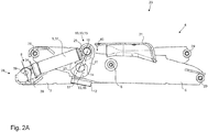
- FIGS. 2A and 2 B show the vehicle seat 1 in a first state 20, ie in a fully compressed state, the FIGS. 3A and 3B the vehicle seat 1 in a third state 22, ie in the state of normal operation, in particular without or with little force, and the FIGS. 4A and 4B the vehicle seat 1 in a second state 21, so a completely rebounded state.
- the first lever member 11 is rotatably connected by a first axis of rotation 17 with the first scissor arm 6, and the second lever member 12 rotatably connected by a second axis of rotation 18 with the second scissor arm 7, and the second end 10 of the damper 5 by means of a third axis of rotation 19 with the first lever member 11 and the second lever member 12.
- the length 38 of the piston rod 36 is indicated as the length of a fourth axis of rotation 39, by means of which the first end 9 of the damper is rotatably connected to the first scissor arm 6, to the Damper housing 37.
- the lever elements 11, 12 are connected only via the respective axes of rotation 17, 18 with the corresponding scissor arms 6, 7. This means that the lever elements 11, 12 are connected directly to the scissor arms 6, 7 by means of the axes of rotation 17, 18.
- FIGS. 2A and 2 B show the vehicle seat in the first state 20, in which the scissors-type frame 4 is completely or maximum springed.
- the first lever element 11 and the second lever element 12 are arranged at an angle 25.
- the angle 25 between a first connecting line 23 which extends between the first axis of rotation 17 and the third axis of rotation 19, and a second connecting line 24 which extends between the second axis of rotation 18 and the third axis of rotation 19 is included.
- this is in the case of the first state 20 to an acute angle 25.
- a distance of the first axis of rotation 17 to the third axis of rotation 19 is greater than a distance of the second axis of rotation 18 to the third axis of rotation 19, whereby a kind of initial condition for the Forced operation of the second end 10 of the damper 5 is given. If the angle 25 would be 0 °, then initially no specific direction of rotation of the second end 10 of the damper 5 would be predetermined. By such a configuration, however, a direction of rotation of the second end 10 is determined in this case, starting in the present case, starting from the first state 20 in initially the third state 22 in the direction of the arrow 40, which indicates the direction of rotation 40. By this direction of rotation 40, in the present case a rotation to the right in the drawing, the second end 10 of the damper 5 moves toward the common axis of rotation 8.
- FIG. 2B shows the subject of the FIG. 2A in a perspective view again. More particularly, two pairs of scissors 41 are shown, each pair of scissors having a first scissor arm 6 and a second scissor arm 7. Likewise, the corresponding lever elements 11, 12 are arranged on each scissor arm 6, 7.
- the entire device is formed symmetrically with respect to a plane E, which is spanned by a height direction H and a longitudinal direction L of the vehicle seat.
- the plane E may partially comprise the damper 5, that is, the damper 5 is arranged so that it is symmetrical to itself.
- FIGS. 3A and 3B show the vehicle seat 1 in the second state 21, that is, the vehicle seat 1 in the normal operating state.
- the length 38 of the piston rod has significantly extended after the damper has performed damping work.
- the second end 10 of the damper 5 has been moved in the direction of the common axis of rotation 8 due to the positive guidance by the first lever element 11 and the second lever element 12.
- the damper 5 is not or only slightly moved. This means that starting from the third state in normal operation, the damping force or the damping effect of the damper 5 is not or only slightly changed. This is referred to as comfort range for the driver, especially when a soft damper characteristic is set.
- the length 38 of the piston rod 36 changes considerably and as a result, the damping, in particular from a soft to a hard damper characteristic in order to avoid a possible end stop.
- the angle 25 between the first connecting line 23 and the second connecting line 24 for the third state 22 may be between 45 ° and 80 °, more preferably between 50 ° and 70 °, and most preferably 60 °.
- FIG. 3B shows in an analogous manner to FIG. 2B the object of FIG. 3A in a perspective view.
- FIGS. 4A and 4B show the vehicle seat in the second state 21, in which the vehicle seat 1 is deflected maximum.
- the length 38 of the piston rod 36 is again significantly reduced.
- the angle 25 between the first connecting line 23 and the second connecting line 24 is in this case essentially 180 °, that is to say the connecting lines 23, 24 are arranged on a common line. Further, it can be seen that the second end 10 has been moved away from the common axis of rotation 8 due to the positive guidance.
- FIGS. 2B and 3B show the FIG. 4B the object of FIG. 4A in a perspective view.
- FIG. 4B is the more detailed embodiment of the lever members 11, 12 can be seen.
- the first lever element 11 is here U-shaped at least in a direction perpendicular to the extension direction of the third axis of rotation 19 and includes a first leg 26 and a second leg 27, wherein the legs 26, 27 are connected to each other by means of a connecting element 42.
- the second leg 27 extends further in the direction of the first connecting line 23 than the first leg 26.
- the second lever element 12 in particular the second end 16 of the second lever element 12, is arranged between the first leg 26 and the second leg 27 in the extension direction of the third axis of rotation 19.
- the second lever element 12 may be plate-like.
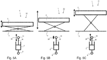
- FIGS. 5A, 5B and 5C show the various states of the vehicle seat 1 again in a schematic representation, in particular, a comparison between the deflection of the vehicle seat 1, in particular the seat shell 2 relative to the seat bottom 3, to the deflection of the damper 5 can be seen.
- the ratio of deflection of the vehicle seat 1 to the deflection of the damper 5, in particular the change in the length 38 of the piston rod 36 is less than or equal to 1 ( ⁇ 1).
- For the second state 21 shown in FIG. 5C is the ratio of deflection of the vehicle seat 1 to the deflection of the damper 5, in particular the change in the length 38 of the piston rod 36, also less than or equal to 1 ( ⁇ 1).
- the ratio of deflection of the vehicle seat 1 to the deflection of the damper 5, in particular the change in the length 38 of the piston rod 36, is greater than 1, in particular much greater than 1 (>> 1).
- a damper characteristic 43 can be achieved, as in the FIG. 6 shown.
- the damper effect changes only slightly, this area being indicated as a comfort area 44.
- the ratio of deflection of the vehicle seat 1 to the deflection of the damper 5 in particular the change in the length 38 of the piston rod 36, greater than 1, in particular much greater than 1 (>> 1). Due to the small deflection of the piston rod 36, the damper characteristic 43 changes in the comfort area 44 only slightly or not at all.
- the regions of the damper characteristic 43 which have a ratio of less than or equal to 1, are assigned to the first state 20 and the second state 21, as also already explained.
- the regions with a ratio of ⁇ 1, ie the regions between the first state 20 and the third state 22 as well as the third state 22 and the second state 21, relate to deflections of the vehicle seat which require increased damping, but not yet in the critical region the end stops lie.
- the damper characteristic 43 increases significantly with a strong deflection of the seat cover 3 up or down in the first state 20 or second state 21, so that an end stop can be prevented or at least mitigated.
- the damper deflection changes little or not at all.
- lever members 11 and 12 can not be attached only to the swinging arms 6, 7. It can also be the combination of seat shell / swing arm or seat bottom / swing arm.
Landscapes
- Engineering & Computer Science (AREA)
- Aviation & Aerospace Engineering (AREA)
- Transportation (AREA)
- Mechanical Engineering (AREA)
- Seats For Vehicles (AREA)
Abstract
Description
- Die Erfindung betrifft einen Fahrzeugsitz mit einem Sitzoberteil und einem Sitzunterteil, wobei das Sitzoberteil und das Sitzunterteil durch ein Scherengestell verbunden sind, und mit einem Dämpfer, wobei das Scherengestell einen ersten Scherenarm und einen zweiten Scherenarm aufweist, wobei der erste Scherenarm und der zweite Scherenarm drehbar um eine gemeinsame Drehachse gelagert sind, wobei ein erstes Ende des Dämpfers mit dem ersten Scherenarm drehbar verbunden ist.
- Derartige Fahrzeugsitze werden in seiner Auslenkungsbewegung, welche durch das Scherengestell geführt wird, mittels eines Dämpfers gedämpft und dadurch Schwingungsbelastungen auf den Fahrzeugführer, welcher auf einem derartigen Fahrzeugsitz Platz genommen hat, reduziert.
- Häufig kommen hierbei Endanschläge zum Einsatz, welche den Fahrzeugsitz im Falle einer vollständigen Auslenkung vor Beschädigungen schützen soll, wobei derartige Endanschläge den Komfort des Fahrzeugsitzes erheblich vermindern.
- Weiter sind Fahrzeugsitze bekannt, welche durch eine Anpassung der Dämpferrate auf verschiedene Fahrsituationen reagieren können, jedoch in einem Normalbetrieb eine zu harte Dämpfung aufweisen, welche für den Fahrzeugführer als nachteilig empfunden und gefühlt wird oder sehr kostenintensiv sind.
- Es ist demzufolge Aufgabe der vorliegenden Erfindung, die Nachteile des Standes der Technik zu überwinden und einen Fahrzeugsitz zu präsentieren, welcher im Normalbetrieb eine komfortable Dämpfung und zusätzlich einen effektiven Endanschlagschutz aufweist.
- Diese Aufgabe wird gemäß den Merkmalen des Patentanspruches 1 gelöst. Vorteilhafte Ausgestaltungen der Erfindung finden sich in den abhängigen Patentansprüchen.
- Kerngedanke der Erfindung ist es, einen Fahrzeugsitz mit einem Sitzoberteil und einem Sitzunterteil bereitzustellen, wobei das Sitzoberteil und das Sitzunterteil durch ein Scherengestell verbunden sind, und mit einem Dämpfer, wobei das Scherengestell einen ersten Scherenarm und einen zweiten Scherenarm aufweist, wobei der erste Scherenarm und der zweite Scherenarm drehbar um eine gemeinsame Drehachse gelagert sind, wobei ein erstes Ende des Dämpfers mit dem ersten Scherenarm drehbar verbunden ist, wobei ein erstes Hebelelement und ein zweites Hebelelement vorgesehen sind, wobei ein erstes Ende des ersten Hebelelementes mit dem ersten Scherenarm drehbar verbunden ist und ein erstes Ende des zweiten Hebelelementes drehbar mit dem zweiten Scherenarm verbunden ist und ein zweites Ende des Dämpfers drehbar sowohl mit einem zweiten Ende des ersten Hebelelements als auch einem zweiten Ende des zweiten Hebelelementes verbunden ist.
- Dies bedeutet insbesondere, dass bei Auslenkung des Fahrzeugsitzes, also einer Bewegung des Scherengestells, zusätzlich zu dem ersten Ende des Dämpfers das zweite Ende des Dämpfers durch das erste Hebelelement und dem zweiten Hebelelement zwangsgeführt wird. Durch eine derartige Zwangsführung ist es insbesondere möglich, durch Veränderung des Abstandes des ersten Endes des Dämpfers und des zweiten Endes des Dämpfers, welche aus der Zwangsführung des zweiten Endes des Dämpfers resultiert, die Dämpferkraft des Dämpfers einzustellen, insbesondere abhängig von der Auslenkbewegung des Scherengestells.
- So ist es insbesondere möglich, die Dämpferkraft im Bereich der Endanschläge, also einer maximalen Auslenkung des Fahrzeugsitzes, deutlich gegenüber dem normalen Fahrbetrieb zu verändern. Im normalen Fahrbetrieb ist eine weiche Dämpfereinstellung bevorzugt, wohingegen im Bereich der Endanschläge eine harte Dämpfereinstellung bevorzugt wird, um eben einen tatsächlichen Endanschlag vermeiden zu können.
- Der Fahrzeugsitz kann für Landfahrzeuge, Nutzfahrzeuge, Agrarfahrzeuge, Baustellenfahrzeuge, sonstige LKW's und PKW's sowie für Boote und Schiffe eingesetzt werden.
- Gemäß einer bevorzugten Ausführungsform sind das erste Ende des ersten Hebelelements mittels einer ersten Drehachse mit dem ersten Scherenarm und das erste Ende des zweiten Hebelelements mittels einer zweiten Drehachse mit dem zweiten Scherenarm drehbar verbunden und das zweite Ende des ersten Hebelelements, das zweite Ende des zweiten Hebelelements und das zweite Ende des Dämpfers mittels einer dritten Schwenkachse verbunden.
- Insbesondere sind das erste Ende des ersten Hebelelements mittels der ersten Drehachse direkt mit dem ersten Scherenarm und das erste Ende des zweiten Hebelelements mittels der zweiten Drehachse direkt mit dem zweiten Scherenarm drehbar verbunden. Direkt bedeutet hierbei, dass keine weiteren Bauteile oder Bauelemente für die Verbindung vorgesehen sind.
- Insbesondere sind die erste Drehachse, die zweite Drehachse und die dritte Drehachse paarweise parallel zueinander angeordnet. Insbesondere verlaufen die erste, zweite und dritte Drehachse sowie die gemeinsame Drehachse in einer Fahrzeugsitzbreitenrichtung des Fahrzeugsitzes.
- Gemäß einer weiteren bevorzugten Ausführungsform schließen in einem ersten Zustand, in welchem der Fahrzeugsitz vollständig eingefedert ist, eine erste Verbindungslinie zwischen der ersten Schwenkachse und der dritten Schwenkachse und eine zweite Verbindungslinie zwischen der zweiten Schwenkachse und der dritten Schwenkachse einen spitzen Winkel ein, wobei der spitze Winkel bevorzugt zwischen 5° und 45° liegt, und wobei der Winkel bevorzugt kleiner als 10°, bevorzugter kleiner als 5° und besonders bevorzugt kleiner als 3° ist.
- Vollständig eingefedert bedeutet hierbei, dass ein Abstand zwischen dem Sitzoberteil und dem Sitzunterteil minimal ist, also das Scherengestell maximal zusammengeklappt ist. Alternativ kann anstelle von vollständig eingefedert auch maximal eingefedert verwendet werden.
- Eine derartige Ausgestaltung ist sinnvoll, um mögliche auftretende Totpunkte in der Bewegung des ersten Hebelelements, des zweiten Hebelelements und entsprechend dem zweiten Ende des Dämpfers zu vermeiden.
- Entsprechend gilt ebenso für eine weitere bevorzugte Ausführungsform, dass in einem zweiten Zustand, in welchem der Fahrzeugsitz vollständig ausgefedert ist, eine erste Verbindungslinie zwischen der ersten Schwenkachse und der dritten Schwenkachse und eine zweite Verbindungslinie zwischen der zweiten Schwenkachse und der dritten Schwenkachse entweder einen stumpfen Winkel einschließen, wobei der Winkel bevorzugt größer als 170° und bevorzugter größer als 175° ist, oder einen Winkel von 180° einschließen.
- Es ist hierbei denkbar, dass der Winkel 180° betragen kann, da aufgrund der Gravitationskraft kein Totpunkt auftreten kann und so eine Bewegung des Sitzoberteils gegenüber dem Sitzunterteil möglich ist.
- Gemäß einer weiteren bevorzugten Ausführungsform ist das erste Hebelelement in zumindest einer Richtung gesehen senkrecht zu der ersten Drehachse U-förmig mit einem ersten Schenkel und einem zweiten Schenkel ausgebildet, wobei der erste Schenkel mit dem ersten Hebelelement und der zweite Schenkel mit der dritten Drehachse drehbar verbunden ist.
- Insbesondere erstrecken sich der erste Schenkel und der zweite Schenkel in Richtung der Verbindungslinie von erster Drehachse und dritter Drehachse. Die Richtung senkrecht zu der ersten Drehachse kann insbesondere senkrecht zu der Verbindungslinie stehen.
- Ebenso vorzugsweise erstreckt sich der zweite Schenkel in Richtung der Verbindungslinie weiter als der erste Schenkel.
- Gemäß einer bevorzugten Ausführungsform ist das zweite Hebelelement plattenähnlich ausgebildet.
- Gemäß einer besonders bevorzugten Ausführungsform ist das zweite Ende des zweiten Hebelelements in Längserstreckungsrichtung der dritten Drehachse gesehen zwischen dem ersten Schenkel und dem zweiten Schenkel angeordnet.
- Das bedeutet, dass insbesondere bei einer U-förmigen Ausgestaltung des ersten Hebelelements das zweite Hebelelement und das erste Hebelelement ineinander eingreifen, wodurch der insgesamte Platzbedarf verringert werden kann.
- Eine gemäß einer bevorzugten Ausführungsform vorgesehene Ausgestaltung des Scherengestells ist derart, dass der erste Scherenarm und der zweite Scherenarm jeweils ein Loslager und ein Festlager aufweisen, wobei das Festlager des ersten Scherenarms mit dem Sitzoberteil und das Festlager des zweiten Scherenarms mit dem Sitzunterteil verbunden sind.
- Insbesondere ist das erste Ende des Dämpfers mit dem Loslager des ersten Scherenarms verbunden. Das heißt, dass bei einer Auslenkung des Scherengestells das erste Ende des Dämpfers entsprechend der Bewegung des ersten Scherenarms folgt.
- Gemäß einer weiteren bevorzugten Ausführungsform ist ein Abstand der ersten Drehachse zu der gemeinsamen Drehachse geringer als ein Abstand der ersten Drehachse zu dem Loslager des ersten Scherenarms, und wobei ein Abstand der zweiten Drehachse zu der gemeinsamen Drehachse geringer ist als ein Abstand der zweiten Drehachse zu dem Loslager des zweiten Scherenarms.
- Hierdurch kann weiterer Bauraum eingespart werden und durch Verkleinerung der Abmessungen der Hebelelemente Materialkosten und Gewicht eingespart werden.
- Weiter sind der Abstand der ersten Drehachse zu der dritten Drehachse und der Abstand der zweiten Drehachse zu der dritten Drehachse im Wesentlichen gleich. Weiter ist es denkbar, dass der Abstand der ersten Drehachse zu der gemeinsamen Drehachse und der Abstand der zweiten Drehachse zu der gemeinsamen Drehachse ebenso im Wesentlichen gleich ausgebildet sind.
- Durch Veränderung der jeweiligen Abstände der Drehachsen zueinander kann die Dämpferrate angepasst werden.
- Gemäß dem erfindungsgemäßen Gegenstand der vorliegenden Anmeldung kann die Dämpferrate derart ausgebildet werden, dass in einem Normalbetrieb eine weiche Dämpfercharakteristik vorherrscht und bei einer Auslenkung in Richtung der maximalen Auslenkung des Fahrzeugsitzes durch Änderung des zweiten Endes des Dämpfers relativ zum ersten Ende des Dämpfers die Dämpferrate angepasst wird.
- Ebenso kann mittels des vorgeschlagenen Fahrzeugsitzes das Verhältnis der Abstandsänderung Sitzoberteil zu Sitzunterteil und Längenänderung des Dämpfers derart ausgebildet werden, dass eine Auslenkung aus dem oder in den ersten Zustand ein Verhältnis von Abstandsänderung Sitzoberteil zu Sitzunterteil zu Längenänderung des Dämpferelements ≤ 1 ist, und eine Auslenkung aus dem oder in den zweiten Zustand ein Verhältnis von Abstandsänderung Sitzoberteil zu Sitzunterteil zu Längenänderung des Dämpferelements ebenfalls ≤ 1 ist.
- In einem dritten Zustand, also dem normalen Betrieb oder Normalzustand, in welchem vorzugsweise der Dämpfungsweg in Fahrzeugsitzhöhenrichtung nach oben und nach unten im Wesentlichen gleich ist, ist das Verhältnis von Abstandsänderung Sitzoberteil zu Sitzunterteil zu Längenänderung des Dämpferelements >>1, also extrem groß, idealerweise unendlich. Das bedeutet, dass eine relativ große Auslenkung des Fahrzeugsitzes lediglich eine kleine Längenänderung des Dämpfers hervorruft. Entsprechend ändert sich die Dämpfungskraft lediglich geringfügig bzw. in einem kleinen Maß.
- Weiter ist es vorteilhaft, wenn der Fahrzeugsitz zusätzlich eine Luftfeder zum Federn des Fahrzeugsitzes umfasst, wobei die Luftfeder einerseits mit dem Scherengestell und andererseits mit dem Sitzoberteil oder dem Sitzunterteil verbunden ist.
- Weiter wird die zugrunde liegende Aufgabe gelöst von einem Nutzfahrzeug umfassend einen Fahrzeugsitz nach einer der beschriebenen Ausführungsformen.
- Weitere vorteilhafte Ausführungsformen ergeben sich aus den Unteransprüchen.
- Weitere Ziele, Vorteile und Zweckmäßigkeiten der vorliegenden Erfindung sind der nachfolgenden Beschreibung in Verbindung mit der Zeichnung zu entnehmen. Hierbei zeigen:
- Fig. 1
- einen Fahrzeugsitz gemäß einer Ausführungsform;
- Fig. 2A, 2B
- einen Fahrzeugsitz gemäß einer Ausführungsform in eingefedertem Zustand in einer Seitenansicht und perspektivischen Ansicht;
- Fig. 3A, 3B
- einen Fahrzeugsitz gemäß einer Ausführungsform im mittleren Zustand in einer Seitenansicht und perspektivischen Ansicht;
- Fig. 4A, 4B
- einen Fahrzeugsitz gemäß einer Ausführungsform mit ausgefedertem Zustand in einer Seitenansicht und perspektivischen Ansicht;
- Fig. 5A, 5B, 5C
- einen Fahrzeugsitz in verschiedenen Auslenkungen und die entsprechenden Dämpferauslenkungen;
- Fig. 6
- eine Darstellung der Kennlinie des Dämpfers.
- In der
Figur 1 ist ein Fahrzeugsitz 1 nach einer besonders bevorzugten Ausführungsform gezeigt, wobei der Fahrzeugsitz 1 ein Sitzoberteil 2 und ein Sitzunterteil 3 aufweist, wobei mit dem Sitzoberteil 2 ein Sitzteil 32 sowie eine Rückenlehne 33 angeordnet sein können. Das Sitzunterteil 3 hingegen ist bevorzugt mit einem Karosserieboden 34 oder dergleichen verbunden. - Wie zu erkennen ist, sind weiter das Sitzoberteil 2 und das Sitzunterteil 3 mittels eines Scherengestells 4 miteinander verbunden, wobei das Scherengestell 4 mindestens einen ersten Scherenarm 6 und mindestens einen zweiten Scherenarm 7 aufweist, wobei der erste Scherenarm 6 und der zweite Scherenarm 7 mittels einer gemeinsamen Drehachse 8 drehbar verbunden sind.
- Dabei ist vorliegend der erste Scherenarm 6 mittels eines Festlagers 29 mit dem Sitzoberteil 2 insbesondere drehbar verbunden, wohingegen der zweite Scherenarm 7 mittels eines Festlagers 29 mit dem Sitzunterteil 3 insbesondere drehbar verbunden ist. Jeder Scherenarm weist darüber hinaus jeweils ein Loslager 28 auf, welches mit dem jeweiligen anderen Fahrzeugsitzteil verbunden ist, beispielsweise für den ersten Scherenarm 6 ist das Loslager mit dem Sitzunterteil 3 verbunden, insbesondere gleitend verbunden.
- Ein erstes Ende 9 des Dämpfers 5 ist mit dem ersten Scherenarm 6 verbunden und ein zweites Ende 10 des Dämpfers 5 ist einerseits mit einem ersten Hebelelement 11 und andererseits mit einem zweiten Hebelelement 12 drehbar verbunden, wobei zusätzlich das erste Hebelelement 11 mit dem ersten Scherenarm 6 und das zweite Hebelelement 12 mit dem zweiten Scherenarm 7 verbunden ist. Insbesondere ist das erste Ende 9 des Dämpfers 5 im Bereich des Loslagers 28 angeordnet, also an einem ersten Ende 35 des ersten Scherenarms 6.
- Bei einer Auslenkung des Fahrzeugsitzes 1, welche ebenso in einer Auslenkung des Scherengestells 4 resultiert, wird das zweite Ende 10 des Dämpfers 5 mittels des ersten Hebelelements 11 und des zweiten Hebelelements 12 zwangsgeführt. Hierdurch ist es möglich, den Abstand des ersten Endes 9 des Dämpfers 5 zu dem zweiten Ende 10 des Dämpfers zu variieren, insbesondere wird hierbei eine Kolbenstange 36 des Dämpfers 5 aus einem oder in ein Dämpfergehäuse 37 verlagert.
- Eine genauere Darstellung wird in den nachfolgenden Figuren gegeben, wobei Bauteile zur Übersichtlichkeit weggelassen werden können.
- Gleiche Bauteile haben die gleichen Bezugszeichen.
- Die
Figuren 2A und2B zeigen den Fahrzeugsitz 1 in einem ersten Zustand 20, also in einem vollständig eingefederten Zustand, dieFiguren 3A und3B den Fahrzeugsitz 1 in einem dritten Zustand 22, also in dem Zustand des normalen Betriebs, insbesondere ohne oder mit geringer Krafteinwirkung, und dieFiguren 4A und4B den Fahrzeugsitz 1 in einem zweiten Zustand 21, also einem vollständig ausgefederten Zustand. - Wie in den
Figuren 2A bis 4B zu erkennen ist, ist das erste Hebelelement 11 mittels einer ersten Drehachse 17 mit dem ersten Scherenarm 6 drehbar verbunden, und das zweite Hebelelement 12 mittels einer zweiten Drehachse 18 mit dem zweiten Scherenarm 7 drehbar verbunden, und das zweite Ende 10 des Dämpfers 5 mittels einer dritten Drehachse 19 mit dem ersten Hebelelement 11 und dem zweiten Hebelelement 12. Die Länge 38 der Kolbenstange 36 ist angegeben als Länge von einer vierten Drehachse 39, mittels welcher das erste Ende 9 des Dämpfers mit dem ersten Scherenarm 6 drehbar verbunden ist, bis zu dem Dämpfergehäuse 37. Insbesondere sind die Hebelelemente 11, 12 lediglich über die entsprechenden Drehachsen 17, 18 mit den entsprechenden Scherenarmen 6, 7 verbunden. Das heißt, dass die Hebelelemente 11, 12 mittels der Drehachsen 17, 18 direkt mit den Scherenarmen 6, 7 verbunden sind. - Die
Figuren 2A und2B zeigen dabei den Fahrzeugsitz in dem ersten Zustand 20, in welchem das Scherengestell 4 vollständig bzw. maximal eingefedert ist. In diesem ersten Zustand 20 sind das erste Hebelelement 11 und das zweite Hebelelement 12 in einem Winkel 25 angeordnet. Dabei ist der Winkel 25 zwischen einer ersten Verbindungslinie 23, welche zwischen der ersten Drehachse 17 und der dritten Drehachse 19 verläuft, und einer zweiten Verbindungslinie 24, welche zwischen der zweiten Drehachse 18 und der dritten Drehachse 19 verläuft, eingeschlossen. Insbesondere handelt es sich hierbei im Falle des ersten Zustands 20 um einen spitzen Winkel 25. Insbesondere ist ein Abstand der ersten Drehachse 17 zu der dritten Drehachse 19 größer als ein Abstand der zweiten Drehachse 18 zu der dritten Drehachse 19, wodurch eine Art Anfangsbedingung für die Zwangsführung des zweiten Endes 10 des Dämpfers 5 gegeben ist. Würde der Winkel 25 0° betragen, so wäre von vornherein zunächst keine bestimmte Drehrichtung des zweiten Endes 10 des Dämpfers 5 vorgegeben. Durch eine derartige Ausgestaltung wird hierbei jedoch eine Drehrichtung des zweiten Endes 10 bestimmt, in dem vorliegenden Fall ausgehend von dem ersten Zustand 20 übergehend in zunächst den dritten Zustand 22 in Richtung des Pfeils 40, welcher die Drehrichtung 40 anzeigt. Durch diese Drehrichtung 40, vorliegend in der Zeichnung eine Drehung nach rechts, bewegt sich das zweite Ende 10 des Dämpfers 5 zu der gemeinsamen Drehachse 8 hin. - Die
Figur 2B zeigt den Gegenstand derFigur 2A in einer perspektivischen Darstellung noch einmal. Genauer sind zwei Scherenpaare 41 gezeigt, wobei jedes Scherenpaar einen ersten Scherenarm 6 und einen zweiten Scherenarm 7 aufweist. Ebenso sind an jedem Scherenarm 6, 7 die entsprechenden Hebelelemente 11, 12 angeordnet. Insbesondere ist die gesamte Vorrichtung symmetrisch ausgebildet in Bezug auf eine Ebene E, welche aufgespannt wird durch eine Höhenrichtung H und eine Längsrichtung L des Fahrzeugsitzes. Insbesondere kann die Ebene E teilweise den Dämpfer 5 aufweisen, das heißt, dass der Dämpfer 5 derart angeordnet ist, dass er zu sich selbst symmetrisch ist. - Die
Figuren 3A und3B zeigen den Fahrzeugsitz 1 in dem zweiten Zustand 21, also den Fahrzeugsitz 1 in dem normalen Betriebszustand. Wie insbesondere aus einem Vergleich derFiguren 2A und3A zu erkennen ist, hat sich die Länge 38 der Kolbenstange deutlich verlängert, nachdem der Dämpfer Dämpfungsarbeit geleistet hat. Weiter aus einem Vergleich ist zu erkennen, dass das zweite Ende 10 des Dämpfers 5 in Richtung der gemeinsamen Drehachse 8 bewegt wurde aufgrund der Zwangsführung durch das erste Hebelelement 11 und das zweite Hebelelement 12. - Befindet sich der Fahrzeugsitz 1 in dem zweiten Zustand 21, so wird aufgrund der Zwangsführung des zweiten Endes 10 des Dämpfers 5 bei einer Auslenkung des Fahrzeugsitzes 1 in Höhenrichtung H gesehen nach oben oder nach unten das zweite Ende 10 des Dämpfers 5 relativ zum ersten Ende 9 des Dämpfers nicht oder nur wenig bewegt. Das bedeutet, dass ausgehend von dem dritten Zustand im normalen Betrieb die Dämpferkraft bzw. die Dämpferwirkung des Dämpfers 5 nicht oder nur wenig verändert wird. Dies wird als Komfortbereich für den Fahrzeugführer bezeichnet, insbesondere dann, wenn eine weiche Dämpfercharakteristik eingestellt ist. Wird der Fahrzeugsitz 1 jedoch aus dem dritten Zustand 22 stark nach oben oder unten ausgelenkt, also in den ersten Zustand 20 oder den zweiten Zustand 21, in welchem der Fahrzeugsitz maximal eingefedert bzw. ausgefedert ist, so ändert sich die Länge 38 der Kolbenstange 36 erheblich und dadurch im Resultat auch die Dämpfung, insbesondere von einer weichen hin zu einer harten Dämpfercharakteristik, um einen möglichen Endanschlag zu vermeiden. Insbesondere kann der Winkel 25 zwischen der ersten Verbindungslinie 23 und der zweiten Verbindungslinie 24 für den dritten Zustand 22 zwischen 45° und 80° betragen, bevorzugter zwischen 50° und 70° und besonders bevorzugt 60° betragen.
- Die
Figur 3B zeigt in analoger Weise zurFigur 2B den Gegenstand derFigur 3A in einer perspektivischen Ansicht. - Die
Figuren 4A und4B zeigen den Fahrzeugsitz in dem zweiten Zustand 21, in welchem der Fahrzeugsitz 1 maximal ausgelenkt ist. - Wie ebenso aus einem Vergleich der
Figur 4A mit derFigur 3A zu erkennen ist, ist die Länge 38 der Kolbenstange 36 wieder erheblich reduziert. Der Winkel 25 zwischen der ersten Verbindungslinie 23 und der zweiten Verbindungslinie 24 beträgt hierbei im Wesentlichen 180°, also die Verbindungslinien 23, 24 sind auf einer gemeinsamen Linie angeordnet. Weiter ist zu erkennen, dass das zweite Ende 10 von der gemeinsamen Drehachse 8 wegbewegt wurde aufgrund der Zwangsführung. - Entsprechend den
Figuren 2B und3B zeigt dieFigur 4B den Gegenstand derFigur 4A in einer perspektivischen Ansicht. - Insbesondere der
Figur 4B ist die genauere Ausgestaltung der Hebelelemente 11, 12 zu entnehmen. Das erste Hebelelement 11 ist hierbei zumindest in einer Richtung senkrecht zu der Erstreckungsrichtung der dritten Drehachse 19 U-förmig ausgebildet und umfasst einen ersten Schenkel 26 und einen zweiten Schenkel 27, wobei die Schenkel 26, 27 mittels eines Verbindungselements 42 miteinander verbunden sind. Vorliegend erstreckt sich der zweite Schenkel 27 in Richtung der ersten Verbindungslinie 23 weiter als der erste Schenkel 26. - Weiter ist den Figuren zu entnehmen, dass das zweite Hebelelement 12, insbesondere das zweite Ende 16 des zweiten Hebelelements 12, in Erstreckungsrichtung der dritten Drehachse 19 gesehen zwischen dem ersten Schenkel 26 und dem zweiten Schenkel 27 angeordnet ist. Das zweite Hebelelement 12 kann plattenähnlich ausgebildet sein.
- Die
Figuren 5A, 5B und 5C zeigen die verschiedenen Zustände des Fahrzeugsitzes 1 nochmals in einer schematischen Darstellung, wobei insbesondere ein Vergleich zwischen der Auslenkung des Fahrzeugsitzes 1, insbesondere des Sitzoberteils 2 gegenüber dem Sitzunterteil 3, zu der Auslenkung des Dämpfers 5 zu erkennen ist. - Für den ersten Zustand 20, gezeigt in der
Figur 5A , ist das Verhältnis von Auslenkung des Fahrzeugsitzes 1 zu der Auslenkung des Dämpfers 5, insbesondere die Änderung der Länge 38 der Kolbenstange 36, kleiner oder gleich 1 (≤ 1). - Für den zweiten Zustand 21, gezeigt in der
Figur 5C , ist das Verhältnis von Auslenkung des Fahrzeugsitzes 1 zu der Auslenkung des Dämpfers 5, insbesondere die Änderung der Länge 38 der Kolbenstange 36, ebenso kleiner oder gleich 1 (≤ 1). - Für den dritten Zustand 22 hingegen, gezeigt in der
Figur 5B , ist das Verhältnis von Auslenkung des Fahrzeugsitzes 1 zu der Auslenkung des Dämpfers 5, insbesondere die Änderung der Länge 38 der Kolbenstange 36, größer als 1, insbesondere sehr viel größer als 1 (>> 1). - Das bedeutet insbesondere, dass bei einer Auslenkung des Sitzoberteils 3 gegenüber dem Sitzunterteil 3 in Richtung nach oben oder nach unten aus dem dritten Zustand 22 heraus in den ersten Zustand 20 oder in den zweiten Zustand 21 die Dämpfercharakteristik aufgrund der Zwangsführung des Dämpfers 5 mittels den Hebelelementen 11, 12 stark ansteigt und die Gefahr eines Endanschlags minimiert.
- Eine derartige Veränderung des Verhältnisses resultiert in einer Dämpfercharakteristik 43, wie sie in der
Figur 6 dargestellt ist. - Durch die Zwangsführung des zweiten Endes 10 des Dämpfers 5 kann eine Dämpfercharakteristik 43 erzielt werden, wie in der
Figur 6 dargestellt. Insbesondere in einem normalen Betrieb ändert sich die Dämpferwirkung nur geringfügig, wobei dieser Bereich als ein Komfortbereich 44 angegeben ist. Wie obig erwähnt, ist im Komfortbereich das Verhältnis von Auslenkung des Fahrzeugsitzes 1 zu der Auslenkung des Dämpfers 5, insbesondere die Änderung der Länge 38 der Kolbenstange 36, größer als 1, insbesondere sehr viel größer als 1 (>> 1). Durch die geringe Auslenkung der Kolbenstange 36 verändert sich die Dämpfercharakteristik 43 in dem Komfortbereich 44 lediglich geringfügig oder auch gar nicht. - Die Bereiche der Dämpfercharakteristik 43, die ein Verhältnis von kleiner oder gleich 1 aufweisen, sind dem ersten Zustand 20 bzw. dem zweiten Zustand 21 zuzuordnen, wie ebenso bereits ausgeführt.
- Die Bereiche mit einem Verhältnis von ≥ 1, also die Bereiche zwischen dem ersten Zustand 20 und dem dritten Zustand 22 sowie dem dritten Zustand 22 und dem zweiten Zustand 21, betreffen Auslenkungen des Fahrzeugsitzes, die eine erhöhte Dämpfung benötigen, jedoch noch nicht im kritischen Bereich der Endanschläge liegen.
- Zusammengefasst erhöht sich aufgrund der Zwangsführung des Dämpfers 5 die Dämpfercharakteristik 43 bei einer starken Auslenkung des Sitzoberteils 3 nach oben oder nach unten in den ersten Zustand 20 oder zweiten Zustand 21 erheblich, so dass ein Endanschlag verhindert werden kann oder zumindest abgeschwächt werden kann. Im normalen Betrieb, also wenn sich der Fahrzeugsitz 1 in einer Mittellage in dem Komfortbereich 44 befindet, ändert sich die Dämpferauslenkung wenig oder sogar gar nicht.
- Grundsätzlich ist auch denkbar beide Dämpferaugen durch einen Hebelmechanismus zu führen. Außerdem können die Hebelelemente 11 und 12 nicht nur an den Schwingenarmen 6, 7 befestigt werden. Es kann auch die Kombination aus Sitzoberteil/Schwingarm oder Sitzunterteil/Schwingarm sein.
- Sämtliche in den Anmeldungsunterlagen offenbarten Merkmale werden als erfindungswesentlich beansprucht, sofern sie einzeln oder in Kombination gegenüber dem Stand der Technik neu sind.
-
- 1
- Fahrzeugsitz
- 2
- Sitzoberteil
- 3
- Sitzunterteil
- 4
- Scherengestell
- 5
- Dämpfer
- 6
- erster Scherenarm
- 7
- zweiter Scherenarm
- 8
- gemeinsame Drehachse
- 9
- erstes Ende des Dämpfers
- 10
- zweites Ende des Dämpfers
- 11
- erstes Hebelelement
- 12
- zweites Hebelelement
- 13
- erstes Ende des ersten Hebelelements
- 14
- zweites Ende des ersten Hebelelements
- 15
- erstes Ende des zweiten Hebelelements
- 16
- zweites Ende des zweiten Hebelelements
- 17
- erste Drehachse
- 18
- zweite Drehachse
- 19
- dritte Drehachse
- 20
- erster Zustand
- 21
- zweiter Zustand
- 22
- dritter Zustand
- 23
- erste Verbindungslinie
- 24
- zweite Verbindungslinie
- 25
- Winkel
- 26
- erster Schenkel
- 27
- zweiter Schenkel
- 28
- Loslager
- 29
- Festlager
- 30
- Luftfeder
- 31
- Luftfederhalterung
- 32
- Sitzteil
- 33
- Rückenlehne
- 34
- Karosserieboden
- 35
- erstes Ende erster Scherenarm
- 36
- Kolbenstange
- 37
- Dämpfergehäuse
- 38
- Länge der Kolbenstange
- 39
- vierte Drehachse
- 40
- Drehrichtung
- 41
- Scherenpaar
- 42
- Verbindungselement
- 43
- Dämpfercharakteristik
- 44
- Komfortbereich
- E
- Ebene
- H
- Höhenrichtung
- B
- Breitenrichtung
- L
- Längsrichtung
Claims (11)
- Fahrzeugsitz (1) mit einem Sitzoberteil (2) und einem Sitzunterteil (3), wobei das Sitzoberteil (2) und das Sitzunterteil (3) durch ein Scherengestell (4) verbunden sind, und mit einem Dämpfer (5), wobei das Scherengestell (4) einen ersten Scherenarm (6) und einen zweiten Scherenarm (7) aufweist, wobei der erste Scherenarm (6) und der zweite Scherenarm (7) drehbar um eine gemeinsame Drehachse (8) gelagert sind, wobei ein erstes Ende (9) des Dämpfers (5) mit dem ersten Scherenarm (6) drehbar verbunden ist,
dadurch gekennzeichnet, dass
ein erstes Hebelelement (11) und ein zweites Hebelelement (12) vorgesehen sind, wobei ein erstes Ende (13) des ersten Hebelelementes (11) mit dem ersten Scherenarm (6) drehbar verbunden ist und ein erstes Ende (15) des zweites Hebelelementes (12) drehbar mit dem zweiten Scherenarm (7) verbunden ist und ein zweites Ende (10) des Dämpfers drehbar sowohl mit einem zweiten Ende (14) des ersten Hebelelements (6) als auch einem zweiten Ende (16) des zweiten Hebelelementes (7) verbunden ist. - Fahrzeugsitz (1) nach Anspruch 1,
dadurch gekennzeichnet, dass
das erste Ende (13) des ersten Hebelelements (6) mittels einer ersten Drehachse (17) mit dem ersten Scherenarm (6) und das erste Ende (15) des zweiten Hebelelements (7) mittels einer zweiten Drehachse (18) mit dem zweiten Scherenarm (7) drehbar verbunden sind und das zweite Ende (14) des ersten Hebelelements (6), das zweite Ende (16) des zweiten Hebelelements (7) und das zweite Ende des Dämpfers (10) mittels einer dritten Schwenkachse (19) verbunden sind. - Fahrzeugsitz (1) nach Anspruch 2,
dadurch gekennzeichnet, dass
in einem ersten Zustand (20), in welchem der Fahrzeugsitz vollständig eingefedert ist, eine erste Verbindungslinie (23) zwischen der ersten Schwenkachse (17) und der dritten Schwenkachse (19) und eine zweite Verbindungslinie (24) zwischen der zweiten Schwenkachse (18) und der dritten Schwenkachse (19) einen spitzen Winkel (25) einschließen, wobei der Winkel (25) bevorzugt kleiner als 10°, bevorzugter kleiner als 5° und besonders bevorzugt kleiner als 3° ist. - Fahrzeugsitz (1) nach Anspruch 2 oder 3,
dadurch gekennzeichnet, dass
in einem zweiten Zustand (21), in welchem der Fahrzeugsitz (1) vollständig ausgefedert ist, eine erste Verbindungslinie (23) zwischen der ersten Schwenkachse (17) und der dritten Schwenkachse (19) und eine zweite Verbindungslinie (24) zwischen der zweiten Schwenkachse (18) und der dritten Schwenkachse (19) entweder einen stumpfen Winkel (25) einschließen, wobei der Winkel (25) bevorzugt größer als 170° und bevorzugter größer als 175° ist, oder einen Winkel (25) von 180° einschließen. - Fahrzeugsitz (1) nach einem der Ansprüche 2 bis 4,
dadurch gekennzeichnet, dass
das erste Hebelelement (11) in zumindest einer Richtung gesehen senkrecht zu der ersten Drehachse (17) U-förmig und mit einem ersten Schenkel (26) und einem zweiten Schenkel (27) ausgebildet ist, wobei der erste Schenkel (26) mit dem ersten Scherenarm (6) und der zweite Schenkel (27) mit der dritten Drehachse (19) drehbar verbunden sind. - Fahrzeugsitz (1) nach einem der Ansprüche 2 bis 5,
dadurch gekennzeichnet, dass
das zweite Hebelelement (12) plattenähnlich ausgebildet ist. - Fahrzeugsitz (1) nach Anspruch 5,
dadurch gekennzeichnet, dass
das zweite Ende (16) des zweiten Hebelelements (12) in Längserstreckungsrichtung der dritten Drehachse (19) gesehen zwischen dem ersten Schenkel (26) und dem zweiten Schenkel (27) angeordnet ist. - Fahrzeugsitz (1) nach einem der Ansprüche 2 bis 7,
dadurch gekennzeichnet, dass
der erste Scherenarm (6) und der zweite Scherenarm (7) jeweils ein Loslager (28) und ein Festlager (29) aufweisen, wobei das Festlager (29) des ersten Scherenarms (6) mit dem Sitzoberteil (2) und das Festlager (29) des zweiten Scherenarms (7) mit dem Sitzunterteil (3) verbunden sind. - Fahrzeugsitz (1) nach Anspruch 8,
dadurch gekennzeichnet, dass
ein Abstand der ersten Drehachse (17) zu der gemeinsamen Drehachse (8) geringer ist als ein Abstand der ersten Drehachse (17) zu dem Loslager (28) des ersten Scherenarms (6), und wobei ein Abstand der zweiten Drehachse (18) zu der gemeinsamen Drehachse (8) geringer ist als ein Abstand der zweiten Drehachse (18) zu dem Loslager (28) des zweiten Scherenarms (7). - Fahrzeugsitz (1) nach einem der vorangegangenen Ansprüche,
dadurch gekennzeichnet, dass
der Fahrzeugsitz (1) zusätzlich eine Luftfeder (30) zum Federn des Fahrzeugsitzes (1) umfasst, wobei die Luftfeder (30) einerseits mit dem Scherengestell (4) und andererseits mit dem Sitzoberteil (2) oder dem Sitzunterteil (3) verbunden ist. - Nutzfahrzeug, umfassend einen Fahrzeugsitz (1) nach einem der Ansprüche 1 bis 10.
Applications Claiming Priority (1)
| Application Number | Priority Date | Filing Date | Title |
|---|---|---|---|
| DE102017115347.0A DE102017115347B4 (de) | 2017-07-10 | 2017-07-10 | Fahrzeugsitz mit einstellbarem Dämpfer und Nutzfahrzeug |
Publications (2)
| Publication Number | Publication Date |
|---|---|
| EP3428009A1 true EP3428009A1 (de) | 2019-01-16 |
| EP3428009B1 EP3428009B1 (de) | 2020-01-01 |
Family
ID=62846053
Family Applications (1)
| Application Number | Title | Priority Date | Filing Date |
|---|---|---|---|
| EP18181430.2A Active EP3428009B1 (de) | 2017-07-10 | 2018-07-03 | Fahrzeugsitz mit einstellbarem dämpfer |
Country Status (3)
| Country | Link |
|---|---|
| US (1) | US10654381B2 (de) |
| EP (1) | EP3428009B1 (de) |
| DE (1) | DE102017115347B4 (de) |
Cited By (6)
| Publication number | Priority date | Publication date | Assignee | Title |
|---|---|---|---|---|
| CN112046358A (zh) * | 2020-10-24 | 2020-12-08 | 浙江龙生汽车部件科技有限公司 | 汽车座椅气囊调节式减震装置及其高度调节方法 |
| DE102019134244A1 (de) * | 2019-12-13 | 2021-06-17 | Grammer Aktiengesellschaft | Fahrzeugsitz mit Scherengestellanordnung |
| US11279271B2 (en) | 2019-12-13 | 2022-03-22 | Grammer Ag | Vehicle seat having a suspension unit for cushioning rolling and vertical suspension movements |
| US11285846B2 (en) | 2019-12-13 | 2022-03-29 | Grammer Ag | Vehicle seat with scissor frame arrangement |
| US12005821B2 (en) | 2019-12-13 | 2024-06-11 | Grammer Ag | Cushioning rolling and vertical suspension movements |
| US12103446B2 (en) | 2019-12-13 | 2024-10-01 | Grammer Ag | Vehicle seat having a suspension unit for cushioning rolling and vertical suspension movements |
Families Citing this family (9)
| Publication number | Priority date | Publication date | Assignee | Title |
|---|---|---|---|---|
| CA2975551C (en) * | 2015-02-20 | 2023-06-20 | The Braun Corporation | Seat base assembly of a vehicle |
| DK179239B9 (da) * | 2016-11-23 | 2018-04-30 | Global Fabtech Shanghai Company Ltd | Mekanisme til en sakselift eller et vippesystem, en sakselift og et vippesystem omfattende en sådan mekanisme og en kørestol med et sædehejs omfattende en sådan sakselift |
| US11618355B2 (en) * | 2018-06-15 | 2023-04-04 | Milsco, Llc | Low profile adjustable vehicle seat mount assembly |
| DE102018124507B4 (de) * | 2018-10-04 | 2020-06-18 | Grammer Ag | Fahrzeugsitz mit Nickfedereinheit |
| DE102018124512B4 (de) * | 2018-10-04 | 2020-09-03 | Grammer Ag | Fahrzeugsitz |
| CN110697052B (zh) * | 2019-09-28 | 2022-12-09 | 湖北航宇嘉泰飞机设备有限公司 | 一种异轴旋转剪切吸能航空座椅 |
| US11872916B2 (en) | 2020-09-24 | 2024-01-16 | Seats Incorporated | Damper system for suspension of vehicle seat |
| CN116118584B (zh) * | 2022-09-27 | 2024-04-19 | 常熟理工学院 | 一种基于多准则优化的磁流变悬挂座椅减振方法 |
| US12036903B1 (en) * | 2023-06-23 | 2024-07-16 | Ford Global Technologies, Llc | Vehicle seat with restraint system |
Citations (3)
| Publication number | Priority date | Publication date | Assignee | Title |
|---|---|---|---|---|
| DE102008023563B3 (de) * | 2008-05-09 | 2009-10-01 | Keiper Gmbh & Co. Kg | Fahrzeugsitz, insbesondere Nutzfahrzeugsitz |
| DE102009041811A1 (de) * | 2009-08-20 | 2011-04-07 | Grammer Ag | Fahrzeugsitz mit einem Dämpfungselement |
| DE102010048210A1 (de) * | 2010-10-13 | 2012-04-19 | Grammer Aktiengesellschaft | Fahrzeugsitz mit Fluidfeder |
Family Cites Families (12)
| Publication number | Priority date | Publication date | Assignee | Title |
|---|---|---|---|---|
| GB1407591A (en) * | 1971-11-27 | 1975-09-24 | Universal Oil Prod Co | Suspension systems for vehicle seats |
| US4448386A (en) * | 1981-12-01 | 1984-05-15 | Uop Inc. | Low profile resilient suspension for vehicle seat |
| US5222709A (en) * | 1990-04-13 | 1993-06-29 | Rosdon Engineering And Manufacturing Pty. Ltd. | Vehicle seat suspension unit |
| US5169112A (en) * | 1991-08-26 | 1992-12-08 | Milsco Manufacturing Company | Electronic suspension vehicle seat |
| DE4429405A1 (de) * | 1994-08-09 | 1996-02-15 | Isringhausen Geb | Schwingfähig abgestützter Fahrzeugsitz mit einer Neigungs- und/oder Höhenverstellung der Sitzfläche |
| US5957426A (en) * | 1997-04-10 | 1999-09-28 | Brodersen; Cole T. | Mechanical seat suspension with multiple position, lift-type height adjuster |
| US6550740B1 (en) | 2002-02-05 | 2003-04-22 | Peter J. Burer | Shock absorbing platform |
| DE102006017774B4 (de) * | 2006-04-15 | 2014-02-13 | Grammer Aktiengesellschaft | Fahrzeugsitz mit einem höhenverstellbaren Sitzgestell |
| DE102010026569B4 (de) * | 2009-07-28 | 2014-03-27 | Grammer Aktiengesellschaft | Regelungseinrichtung zur Reduzierung einer Schwingungsbewegung einer federkraftbeaufschlagten schwingenden Vorrichtung |
| US9527416B2 (en) * | 2012-05-21 | 2016-12-27 | Sears Manufacturing Co. | Vehicle seat scissors suspension with integrated stabilized isolator |
| US9782005B2 (en) * | 2014-07-25 | 2017-10-10 | Stryker Corporation | Medical support apparatus |
| DE102013021057B4 (de) | 2013-12-18 | 2017-06-08 | Grammer Ag | Druckminderer |
-
2017
- 2017-07-10 DE DE102017115347.0A patent/DE102017115347B4/de active Active
-
2018
- 2018-07-03 EP EP18181430.2A patent/EP3428009B1/de active Active
- 2018-07-10 US US16/031,052 patent/US10654381B2/en active Active
Patent Citations (3)
| Publication number | Priority date | Publication date | Assignee | Title |
|---|---|---|---|---|
| DE102008023563B3 (de) * | 2008-05-09 | 2009-10-01 | Keiper Gmbh & Co. Kg | Fahrzeugsitz, insbesondere Nutzfahrzeugsitz |
| DE102009041811A1 (de) * | 2009-08-20 | 2011-04-07 | Grammer Ag | Fahrzeugsitz mit einem Dämpfungselement |
| DE102010048210A1 (de) * | 2010-10-13 | 2012-04-19 | Grammer Aktiengesellschaft | Fahrzeugsitz mit Fluidfeder |
Cited By (8)
| Publication number | Priority date | Publication date | Assignee | Title |
|---|---|---|---|---|
| DE102019134244A1 (de) * | 2019-12-13 | 2021-06-17 | Grammer Aktiengesellschaft | Fahrzeugsitz mit Scherengestellanordnung |
| US11279271B2 (en) | 2019-12-13 | 2022-03-22 | Grammer Ag | Vehicle seat having a suspension unit for cushioning rolling and vertical suspension movements |
| US11285846B2 (en) | 2019-12-13 | 2022-03-29 | Grammer Ag | Vehicle seat with scissor frame arrangement |
| US11685298B2 (en) | 2019-12-13 | 2023-06-27 | Grammer Ag | Vehicle seat with scissor frame arrangement |
| US12005821B2 (en) | 2019-12-13 | 2024-06-11 | Grammer Ag | Cushioning rolling and vertical suspension movements |
| DE102019134244B4 (de) | 2019-12-13 | 2024-08-01 | Grammer Aktiengesellschaft | Fahrzeugsitz mit Scherengestellanordnung |
| US12103446B2 (en) | 2019-12-13 | 2024-10-01 | Grammer Ag | Vehicle seat having a suspension unit for cushioning rolling and vertical suspension movements |
| CN112046358A (zh) * | 2020-10-24 | 2020-12-08 | 浙江龙生汽车部件科技有限公司 | 汽车座椅气囊调节式减震装置及其高度调节方法 |
Also Published As
| Publication number | Publication date |
|---|---|
| DE102017115347B4 (de) | 2020-07-02 |
| US10654381B2 (en) | 2020-05-19 |
| US20190009697A1 (en) | 2019-01-10 |
| DE102017115347A1 (de) | 2019-01-10 |
| EP3428009B1 (de) | 2020-01-01 |
Similar Documents
| Publication | Publication Date | Title |
|---|---|---|
| EP3428009B1 (de) | Fahrzeugsitz mit einstellbarem dämpfer | |
| DE102008056200B4 (de) | Scherengestell für einen Fahrzeugsitz, Fahrzeugsitz, insbesondere Kraftfahrzeugsitz, und Verfahren zum Herstellen eines Unterbaus eines Fahrzeugsitzes | |
| DE102017119698B4 (de) | Kindersicherheitssitz und Mechanismus zur Abstandsverstellung der Sitzwangen | |
| EP3181396B1 (de) | Fahrzeugschwingungsvorrichtung | |
| EP2423039B1 (de) | Fahrzeugschwingungsabfangsvorrichtung | |
| DE68906457T2 (de) | Aufhängungseinrichtung mit einem Nockenunterstützungselement. | |
| EP2818345B1 (de) | Vorrichtung mit einem Federungssystem | |
| EP3572275B1 (de) | Fahrzeugsitz | |
| DE102010026569A1 (de) | Regelungseinrichtung zur Reduzierung einer Schwingungsbewegung einer federkraftbeaufschlagten schwingenden Vorrichtung | |
| DE102019122528A1 (de) | Abdeckungsvorrichtung für Fahrzeugsitze | |
| EP3569443A1 (de) | Fahrzeugsitz mit einer federeinrichtung | |
| EP3835116A1 (de) | Fahrzeugsitz mit scherengestellanordnung | |
| EP3763561B1 (de) | Fahrzeugsitz mit scherengestell | |
| EP3181397B1 (de) | Fahrzeugschwingungsvorrichtung | |
| DE102015117820B4 (de) | Vorrichtung zum Federn und/oder Dämpfen eines Oberteils gegenüber einem Unterteil und Fahrzeugsitz mit dieser Vorrichtung | |
| EP2223823B1 (de) | Federungsvorrichtung für Fahrzeugsitze sowie Fahrzeugsitzaufhängung | |
| EP3626520B1 (de) | Abdeckungsvorrichtung für fahrzeugsitze | |
| EP3835121B1 (de) | Fahrzeugsitz mit einer federeinheit zum federn von wank- und vertikalfederbewegung | |
| EP0449165B1 (de) | Sitzanordnung, insbesondere für ein Kraftfahrzeug | |
| DE102020110757B3 (de) | Fahrzeugsitz | |
| EP3335929A1 (de) | Fahrzeugsitz mit federung | |
| DE102018112019B4 (de) | Fahrzeugsitz mit einer Dämpfungseinrichtung | |
| DE102012200550B4 (de) | Sitzanordnung mit einem verstellbaren Dämpfmechanismus |
Legal Events
| Date | Code | Title | Description |
|---|---|---|---|
| PUAI | Public reference made under article 153(3) epc to a published international application that has entered the european phase |
Free format text: ORIGINAL CODE: 0009012 |
|
| STAA | Information on the status of an ep patent application or granted ep patent |
Free format text: STATUS: THE APPLICATION HAS BEEN PUBLISHED |
|
| AK | Designated contracting states |
Kind code of ref document: A1 Designated state(s): AL AT BE BG CH CY CZ DE DK EE ES FI FR GB GR HR HU IE IS IT LI LT LU LV MC MK MT NL NO PL PT RO RS SE SI SK SM TR |
|
| AX | Request for extension of the european patent |
Extension state: BA ME |
|
| STAA | Information on the status of an ep patent application or granted ep patent |
Free format text: STATUS: REQUEST FOR EXAMINATION WAS MADE |
|
| 17P | Request for examination filed |
Effective date: 20190124 |
|
| RBV | Designated contracting states (corrected) |
Designated state(s): AL AT BE BG CH CY CZ DE DK EE ES FI FR GB GR HR HU IE IS IT LI LT LU LV MC MK MT NL NO PL PT RO RS SE SI SK SM TR |
|
| GRAP | Despatch of communication of intention to grant a patent |
Free format text: ORIGINAL CODE: EPIDOSNIGR1 |
|
| RIC1 | Information provided on ipc code assigned before grant |
Ipc: B60N 2/52 20060101ALI20190626BHEP Ipc: B60N 2/50 20060101AFI20190626BHEP |
|
| STAA | Information on the status of an ep patent application or granted ep patent |
Free format text: STATUS: GRANT OF PATENT IS INTENDED |
|
| INTG | Intention to grant announced |
Effective date: 20190801 |
|
| GRAS | Grant fee paid |
Free format text: ORIGINAL CODE: EPIDOSNIGR3 |
|
| GRAA | (expected) grant |
Free format text: ORIGINAL CODE: 0009210 |
|
| STAA | Information on the status of an ep patent application or granted ep patent |
Free format text: STATUS: THE PATENT HAS BEEN GRANTED |
|
| AK | Designated contracting states |
Kind code of ref document: B1 Designated state(s): AL AT BE BG CH CY CZ DE DK EE ES FI FR GB GR HR HU IE IS IT LI LT LU LV MC MK MT NL NO PL PT RO RS SE SI SK SM TR |
|
| REG | Reference to a national code |
Ref country code: GB Ref legal event code: FG4D Free format text: NOT ENGLISH |
|
| REG | Reference to a national code |
Ref country code: CH Ref legal event code: EP Ref country code: AT Ref legal event code: REF Ref document number: 1219386 Country of ref document: AT Kind code of ref document: T Effective date: 20200115 |
|
| REG | Reference to a national code |
Ref country code: DE Ref legal event code: R096 Ref document number: 502018000588 Country of ref document: DE |
|
| REG | Reference to a national code |
Ref country code: IE Ref legal event code: FG4D Free format text: LANGUAGE OF EP DOCUMENT: GERMAN |
|
| REG | Reference to a national code |
Ref country code: NL Ref legal event code: MP Effective date: 20200101 |
|
| REG | Reference to a national code |
Ref country code: LT Ref legal event code: MG4D |
|
| PG25 | Lapsed in a contracting state [announced via postgrant information from national office to epo] |
Ref country code: NO Free format text: LAPSE BECAUSE OF FAILURE TO SUBMIT A TRANSLATION OF THE DESCRIPTION OR TO PAY THE FEE WITHIN THE PRESCRIBED TIME-LIMIT Effective date: 20200401 Ref country code: FI Free format text: LAPSE BECAUSE OF FAILURE TO SUBMIT A TRANSLATION OF THE DESCRIPTION OR TO PAY THE FEE WITHIN THE PRESCRIBED TIME-LIMIT Effective date: 20200101 Ref country code: NL Free format text: LAPSE BECAUSE OF FAILURE TO SUBMIT A TRANSLATION OF THE DESCRIPTION OR TO PAY THE FEE WITHIN THE PRESCRIBED TIME-LIMIT Effective date: 20200101 Ref country code: RS Free format text: LAPSE BECAUSE OF FAILURE TO SUBMIT A TRANSLATION OF THE DESCRIPTION OR TO PAY THE FEE WITHIN THE PRESCRIBED TIME-LIMIT Effective date: 20200101 Ref country code: LT Free format text: LAPSE BECAUSE OF FAILURE TO SUBMIT A TRANSLATION OF THE DESCRIPTION OR TO PAY THE FEE WITHIN THE PRESCRIBED TIME-LIMIT Effective date: 20200101 Ref country code: CZ Free format text: LAPSE BECAUSE OF FAILURE TO SUBMIT A TRANSLATION OF THE DESCRIPTION OR TO PAY THE FEE WITHIN THE PRESCRIBED TIME-LIMIT Effective date: 20200101 Ref country code: PT Free format text: LAPSE BECAUSE OF FAILURE TO SUBMIT A TRANSLATION OF THE DESCRIPTION OR TO PAY THE FEE WITHIN THE PRESCRIBED TIME-LIMIT Effective date: 20200527 |
|
| PG25 | Lapsed in a contracting state [announced via postgrant information from national office to epo] |
Ref country code: IS Free format text: LAPSE BECAUSE OF FAILURE TO SUBMIT A TRANSLATION OF THE DESCRIPTION OR TO PAY THE FEE WITHIN THE PRESCRIBED TIME-LIMIT Effective date: 20200501 Ref country code: BG Free format text: LAPSE BECAUSE OF FAILURE TO SUBMIT A TRANSLATION OF THE DESCRIPTION OR TO PAY THE FEE WITHIN THE PRESCRIBED TIME-LIMIT Effective date: 20200401 Ref country code: GR Free format text: LAPSE BECAUSE OF FAILURE TO SUBMIT A TRANSLATION OF THE DESCRIPTION OR TO PAY THE FEE WITHIN THE PRESCRIBED TIME-LIMIT Effective date: 20200402 Ref country code: SE Free format text: LAPSE BECAUSE OF FAILURE TO SUBMIT A TRANSLATION OF THE DESCRIPTION OR TO PAY THE FEE WITHIN THE PRESCRIBED TIME-LIMIT Effective date: 20200101 Ref country code: LV Free format text: LAPSE BECAUSE OF FAILURE TO SUBMIT A TRANSLATION OF THE DESCRIPTION OR TO PAY THE FEE WITHIN THE PRESCRIBED TIME-LIMIT Effective date: 20200101 Ref country code: HR Free format text: LAPSE BECAUSE OF FAILURE TO SUBMIT A TRANSLATION OF THE DESCRIPTION OR TO PAY THE FEE WITHIN THE PRESCRIBED TIME-LIMIT Effective date: 20200101 |
|
| REG | Reference to a national code |
Ref country code: DE Ref legal event code: R097 Ref document number: 502018000588 Country of ref document: DE |
|
| RAP2 | Party data changed (patent owner data changed or rights of a patent transferred) |
Owner name: GRAMMER AG |
|
| PG25 | Lapsed in a contracting state [announced via postgrant information from national office to epo] |
Ref country code: ES Free format text: LAPSE BECAUSE OF FAILURE TO SUBMIT A TRANSLATION OF THE DESCRIPTION OR TO PAY THE FEE WITHIN THE PRESCRIBED TIME-LIMIT Effective date: 20200101 Ref country code: SK Free format text: LAPSE BECAUSE OF FAILURE TO SUBMIT A TRANSLATION OF THE DESCRIPTION OR TO PAY THE FEE WITHIN THE PRESCRIBED TIME-LIMIT Effective date: 20200101 Ref country code: RO Free format text: LAPSE BECAUSE OF FAILURE TO SUBMIT A TRANSLATION OF THE DESCRIPTION OR TO PAY THE FEE WITHIN THE PRESCRIBED TIME-LIMIT Effective date: 20200101 Ref country code: DK Free format text: LAPSE BECAUSE OF FAILURE TO SUBMIT A TRANSLATION OF THE DESCRIPTION OR TO PAY THE FEE WITHIN THE PRESCRIBED TIME-LIMIT Effective date: 20200101 Ref country code: SM Free format text: LAPSE BECAUSE OF FAILURE TO SUBMIT A TRANSLATION OF THE DESCRIPTION OR TO PAY THE FEE WITHIN THE PRESCRIBED TIME-LIMIT Effective date: 20200101 Ref country code: EE Free format text: LAPSE BECAUSE OF FAILURE TO SUBMIT A TRANSLATION OF THE DESCRIPTION OR TO PAY THE FEE WITHIN THE PRESCRIBED TIME-LIMIT Effective date: 20200101 |
|
| PLBE | No opposition filed within time limit |
Free format text: ORIGINAL CODE: 0009261 |
|
| STAA | Information on the status of an ep patent application or granted ep patent |
Free format text: STATUS: NO OPPOSITION FILED WITHIN TIME LIMIT |
|
| 26N | No opposition filed |
Effective date: 20201002 |
|
| PG25 | Lapsed in a contracting state [announced via postgrant information from national office to epo] |
Ref country code: PL Free format text: LAPSE BECAUSE OF FAILURE TO SUBMIT A TRANSLATION OF THE DESCRIPTION OR TO PAY THE FEE WITHIN THE PRESCRIBED TIME-LIMIT Effective date: 20200101 Ref country code: SI Free format text: LAPSE BECAUSE OF FAILURE TO SUBMIT A TRANSLATION OF THE DESCRIPTION OR TO PAY THE FEE WITHIN THE PRESCRIBED TIME-LIMIT Effective date: 20200101 Ref country code: MC Free format text: LAPSE BECAUSE OF FAILURE TO SUBMIT A TRANSLATION OF THE DESCRIPTION OR TO PAY THE FEE WITHIN THE PRESCRIBED TIME-LIMIT Effective date: 20200101 |
|
| REG | Reference to a national code |
Ref country code: BE Ref legal event code: MM Effective date: 20200731 |
|
| PG25 | Lapsed in a contracting state [announced via postgrant information from national office to epo] |
Ref country code: IE Free format text: LAPSE BECAUSE OF NON-PAYMENT OF DUE FEES Effective date: 20200703 Ref country code: LU Free format text: LAPSE BECAUSE OF NON-PAYMENT OF DUE FEES Effective date: 20200703 |
|
| PG25 | Lapsed in a contracting state [announced via postgrant information from national office to epo] |
Ref country code: BE Free format text: LAPSE BECAUSE OF NON-PAYMENT OF DUE FEES Effective date: 20200731 |
|
| REG | Reference to a national code |
Ref country code: CH Ref legal event code: PL |
|
| PG25 | Lapsed in a contracting state [announced via postgrant information from national office to epo] |
Ref country code: LI Free format text: LAPSE BECAUSE OF NON-PAYMENT OF DUE FEES Effective date: 20210731 Ref country code: CH Free format text: LAPSE BECAUSE OF NON-PAYMENT OF DUE FEES Effective date: 20210731 |
|
| PG25 | Lapsed in a contracting state [announced via postgrant information from national office to epo] |
Ref country code: TR Free format text: LAPSE BECAUSE OF FAILURE TO SUBMIT A TRANSLATION OF THE DESCRIPTION OR TO PAY THE FEE WITHIN THE PRESCRIBED TIME-LIMIT Effective date: 20200101 Ref country code: MT Free format text: LAPSE BECAUSE OF FAILURE TO SUBMIT A TRANSLATION OF THE DESCRIPTION OR TO PAY THE FEE WITHIN THE PRESCRIBED TIME-LIMIT Effective date: 20200101 Ref country code: CY Free format text: LAPSE BECAUSE OF FAILURE TO SUBMIT A TRANSLATION OF THE DESCRIPTION OR TO PAY THE FEE WITHIN THE PRESCRIBED TIME-LIMIT Effective date: 20200101 |
|
| PG25 | Lapsed in a contracting state [announced via postgrant information from national office to epo] |
Ref country code: MK Free format text: LAPSE BECAUSE OF FAILURE TO SUBMIT A TRANSLATION OF THE DESCRIPTION OR TO PAY THE FEE WITHIN THE PRESCRIBED TIME-LIMIT Effective date: 20200101 Ref country code: AL Free format text: LAPSE BECAUSE OF FAILURE TO SUBMIT A TRANSLATION OF THE DESCRIPTION OR TO PAY THE FEE WITHIN THE PRESCRIBED TIME-LIMIT Effective date: 20200101 |
|
| GBPC | Gb: european patent ceased through non-payment of renewal fee |
Effective date: 20220703 |
|
| PG25 | Lapsed in a contracting state [announced via postgrant information from national office to epo] |
Ref country code: GB Free format text: LAPSE BECAUSE OF NON-PAYMENT OF DUE FEES Effective date: 20220703 |
|
| REG | Reference to a national code |
Ref country code: AT Ref legal event code: MM01 Ref document number: 1219386 Country of ref document: AT Kind code of ref document: T Effective date: 20230703 |
|
| PG25 | Lapsed in a contracting state [announced via postgrant information from national office to epo] |
Ref country code: AT Free format text: LAPSE BECAUSE OF NON-PAYMENT OF DUE FEES Effective date: 20230703 |
|
| PG25 | Lapsed in a contracting state [announced via postgrant information from national office to epo] |
Ref country code: AT Free format text: LAPSE BECAUSE OF NON-PAYMENT OF DUE FEES Effective date: 20230703 |
|
| PGFP | Annual fee paid to national office [announced via postgrant information from national office to epo] |
Ref country code: DE Payment date: 20250722 Year of fee payment: 8 |
|
| PGFP | Annual fee paid to national office [announced via postgrant information from national office to epo] |
Ref country code: IT Payment date: 20250731 Year of fee payment: 8 |
|
| PGFP | Annual fee paid to national office [announced via postgrant information from national office to epo] |
Ref country code: FR Payment date: 20250723 Year of fee payment: 8 |
|
| PGFP | Annual fee paid to national office [announced via postgrant information from national office to epo] |
Ref country code: AT Payment date: 20260410 Year of fee payment: 5 |