EP3427932A1 - Joined member assembly method and joined member - Google Patents
Joined member assembly method and joined member Download PDFInfo
- Publication number
- EP3427932A1 EP3427932A1 EP17827458.5A EP17827458A EP3427932A1 EP 3427932 A1 EP3427932 A1 EP 3427932A1 EP 17827458 A EP17827458 A EP 17827458A EP 3427932 A1 EP3427932 A1 EP 3427932A1
- Authority
- EP
- European Patent Office
- Prior art keywords
- base material
- resin
- gap
- joined member
- multilayer structure
- Prior art date
- Legal status (The legal status is an assumption and is not a legal conclusion. Google has not performed a legal analysis and makes no representation as to the accuracy of the status listed.)
- Withdrawn
Links
Images




Classifications
-
- B—PERFORMING OPERATIONS; TRANSPORTING
- B32—LAYERED PRODUCTS
- B32B—LAYERED PRODUCTS, i.e. PRODUCTS BUILT-UP OF STRATA OF FLAT OR NON-FLAT, e.g. CELLULAR OR HONEYCOMB, FORM
- B32B15/00—Layered products comprising a layer of metal
- B32B15/14—Layered products comprising a layer of metal next to a fibrous or filamentary layer
-
- B—PERFORMING OPERATIONS; TRANSPORTING
- B29—WORKING OF PLASTICS; WORKING OF SUBSTANCES IN A PLASTIC STATE IN GENERAL
- B29C—SHAPING OR JOINING OF PLASTICS; SHAPING OF MATERIAL IN A PLASTIC STATE, NOT OTHERWISE PROVIDED FOR; AFTER-TREATMENT OF THE SHAPED PRODUCTS, e.g. REPAIRING
- B29C65/00—Joining or sealing of preformed parts, e.g. welding of plastics materials; Apparatus therefor
- B29C65/66—Joining or sealing of preformed parts, e.g. welding of plastics materials; Apparatus therefor by liberation of internal stresses, e.g. shrinking of one of the parts to be joined
- B29C65/68—Joining or sealing of preformed parts, e.g. welding of plastics materials; Apparatus therefor by liberation of internal stresses, e.g. shrinking of one of the parts to be joined using auxiliary shrinkable elements
-
- B—PERFORMING OPERATIONS; TRANSPORTING
- B29—WORKING OF PLASTICS; WORKING OF SUBSTANCES IN A PLASTIC STATE IN GENERAL
- B29C—SHAPING OR JOINING OF PLASTICS; SHAPING OF MATERIAL IN A PLASTIC STATE, NOT OTHERWISE PROVIDED FOR; AFTER-TREATMENT OF THE SHAPED PRODUCTS, e.g. REPAIRING
- B29C70/00—Shaping composites, i.e. plastics material comprising reinforcements, fillers or preformed parts, e.g. inserts
- B29C70/04—Shaping composites, i.e. plastics material comprising reinforcements, fillers or preformed parts, e.g. inserts comprising reinforcements only, e.g. self-reinforcing plastics
- B29C70/06—Fibrous reinforcements only
- B29C70/10—Fibrous reinforcements only characterised by the structure of fibrous reinforcements, e.g. hollow fibres
- B29C70/16—Fibrous reinforcements only characterised by the structure of fibrous reinforcements, e.g. hollow fibres using fibres of substantial or continuous length
- B29C70/24—Fibrous reinforcements only characterised by the structure of fibrous reinforcements, e.g. hollow fibres using fibres of substantial or continuous length oriented in at least three directions forming a three-dimensional [3D] structure
-
- B—PERFORMING OPERATIONS; TRANSPORTING
- B29—WORKING OF PLASTICS; WORKING OF SUBSTANCES IN A PLASTIC STATE IN GENERAL
- B29C—SHAPING OR JOINING OF PLASTICS; SHAPING OF MATERIAL IN A PLASTIC STATE, NOT OTHERWISE PROVIDED FOR; AFTER-TREATMENT OF THE SHAPED PRODUCTS, e.g. REPAIRING
- B29C70/00—Shaping composites, i.e. plastics material comprising reinforcements, fillers or preformed parts, e.g. inserts
- B29C70/04—Shaping composites, i.e. plastics material comprising reinforcements, fillers or preformed parts, e.g. inserts comprising reinforcements only, e.g. self-reinforcing plastics
- B29C70/28—Shaping operations therefor
- B29C70/40—Shaping or impregnating by compression not applied
- B29C70/42—Shaping or impregnating by compression not applied for producing articles of definite length, i.e. discrete articles
- B29C70/44—Shaping or impregnating by compression not applied for producing articles of definite length, i.e. discrete articles using isostatic pressure, e.g. pressure difference-moulding, vacuum bag-moulding, autoclave-moulding or expanding rubber-moulding
- B29C70/443—Shaping or impregnating by compression not applied for producing articles of definite length, i.e. discrete articles using isostatic pressure, e.g. pressure difference-moulding, vacuum bag-moulding, autoclave-moulding or expanding rubber-moulding and impregnating by vacuum or injection
-
- B—PERFORMING OPERATIONS; TRANSPORTING
- B32—LAYERED PRODUCTS
- B32B—LAYERED PRODUCTS, i.e. PRODUCTS BUILT-UP OF STRATA OF FLAT OR NON-FLAT, e.g. CELLULAR OR HONEYCOMB, FORM
- B32B5/00—Layered products characterised by the non- homogeneity or physical structure, i.e. comprising a fibrous, filamentary, particulate or foam layer; Layered products characterised by having a layer differing constitutionally or physically in different parts
- B32B5/02—Layered products characterised by the non- homogeneity or physical structure, i.e. comprising a fibrous, filamentary, particulate or foam layer; Layered products characterised by having a layer differing constitutionally or physically in different parts characterised by structural features of a fibrous or filamentary layer
- B32B5/024—Woven fabric
-
- B—PERFORMING OPERATIONS; TRANSPORTING
- B32—LAYERED PRODUCTS
- B32B—LAYERED PRODUCTS, i.e. PRODUCTS BUILT-UP OF STRATA OF FLAT OR NON-FLAT, e.g. CELLULAR OR HONEYCOMB, FORM
- B32B5/00—Layered products characterised by the non- homogeneity or physical structure, i.e. comprising a fibrous, filamentary, particulate or foam layer; Layered products characterised by having a layer differing constitutionally or physically in different parts
- B32B5/02—Layered products characterised by the non- homogeneity or physical structure, i.e. comprising a fibrous, filamentary, particulate or foam layer; Layered products characterised by having a layer differing constitutionally or physically in different parts characterised by structural features of a fibrous or filamentary layer
- B32B5/04—Layered products characterised by the non- homogeneity or physical structure, i.e. comprising a fibrous, filamentary, particulate or foam layer; Layered products characterised by having a layer differing constitutionally or physically in different parts characterised by structural features of a fibrous or filamentary layer characterised by a layer being specifically extensible by reason of its structure or arrangement, e.g. by reason of the chemical nature of the fibres or filaments
-
- B—PERFORMING OPERATIONS; TRANSPORTING
- B32—LAYERED PRODUCTS
- B32B—LAYERED PRODUCTS, i.e. PRODUCTS BUILT-UP OF STRATA OF FLAT OR NON-FLAT, e.g. CELLULAR OR HONEYCOMB, FORM
- B32B5/00—Layered products characterised by the non- homogeneity or physical structure, i.e. comprising a fibrous, filamentary, particulate or foam layer; Layered products characterised by having a layer differing constitutionally or physically in different parts
- B32B5/02—Layered products characterised by the non- homogeneity or physical structure, i.e. comprising a fibrous, filamentary, particulate or foam layer; Layered products characterised by having a layer differing constitutionally or physically in different parts characterised by structural features of a fibrous or filamentary layer
- B32B5/06—Layered products characterised by the non- homogeneity or physical structure, i.e. comprising a fibrous, filamentary, particulate or foam layer; Layered products characterised by having a layer differing constitutionally or physically in different parts characterised by structural features of a fibrous or filamentary layer characterised by a fibrous or filamentary layer mechanically connected, e.g. by needling to another layer, e.g. of fibres, of paper
-
- B—PERFORMING OPERATIONS; TRANSPORTING
- B32—LAYERED PRODUCTS
- B32B—LAYERED PRODUCTS, i.e. PRODUCTS BUILT-UP OF STRATA OF FLAT OR NON-FLAT, e.g. CELLULAR OR HONEYCOMB, FORM
- B32B5/00—Layered products characterised by the non- homogeneity or physical structure, i.e. comprising a fibrous, filamentary, particulate or foam layer; Layered products characterised by having a layer differing constitutionally or physically in different parts
- B32B5/02—Layered products characterised by the non- homogeneity or physical structure, i.e. comprising a fibrous, filamentary, particulate or foam layer; Layered products characterised by having a layer differing constitutionally or physically in different parts characterised by structural features of a fibrous or filamentary layer
- B32B5/08—Layered products characterised by the non- homogeneity or physical structure, i.e. comprising a fibrous, filamentary, particulate or foam layer; Layered products characterised by having a layer differing constitutionally or physically in different parts characterised by structural features of a fibrous or filamentary layer the fibres or filaments of a layer being of different substances, e.g. conjugate fibres, mixture of different fibres
-
- B—PERFORMING OPERATIONS; TRANSPORTING
- B32—LAYERED PRODUCTS
- B32B—LAYERED PRODUCTS, i.e. PRODUCTS BUILT-UP OF STRATA OF FLAT OR NON-FLAT, e.g. CELLULAR OR HONEYCOMB, FORM
- B32B5/00—Layered products characterised by the non- homogeneity or physical structure, i.e. comprising a fibrous, filamentary, particulate or foam layer; Layered products characterised by having a layer differing constitutionally or physically in different parts
- B32B5/02—Layered products characterised by the non- homogeneity or physical structure, i.e. comprising a fibrous, filamentary, particulate or foam layer; Layered products characterised by having a layer differing constitutionally or physically in different parts characterised by structural features of a fibrous or filamentary layer
- B32B5/10—Layered products characterised by the non- homogeneity or physical structure, i.e. comprising a fibrous, filamentary, particulate or foam layer; Layered products characterised by having a layer differing constitutionally or physically in different parts characterised by structural features of a fibrous or filamentary layer characterised by a fibrous or filamentary layer reinforced with filaments
-
- B—PERFORMING OPERATIONS; TRANSPORTING
- B32—LAYERED PRODUCTS
- B32B—LAYERED PRODUCTS, i.e. PRODUCTS BUILT-UP OF STRATA OF FLAT OR NON-FLAT, e.g. CELLULAR OR HONEYCOMB, FORM
- B32B5/00—Layered products characterised by the non- homogeneity or physical structure, i.e. comprising a fibrous, filamentary, particulate or foam layer; Layered products characterised by having a layer differing constitutionally or physically in different parts
- B32B5/22—Layered products characterised by the non- homogeneity or physical structure, i.e. comprising a fibrous, filamentary, particulate or foam layer; Layered products characterised by having a layer differing constitutionally or physically in different parts characterised by the presence of two or more layers which are next to each other and are fibrous, filamentary, formed of particles or foamed
- B32B5/24—Layered products characterised by the non- homogeneity or physical structure, i.e. comprising a fibrous, filamentary, particulate or foam layer; Layered products characterised by having a layer differing constitutionally or physically in different parts characterised by the presence of two or more layers which are next to each other and are fibrous, filamentary, formed of particles or foamed one layer being a fibrous or filamentary layer
- B32B5/26—Layered products characterised by the non- homogeneity or physical structure, i.e. comprising a fibrous, filamentary, particulate or foam layer; Layered products characterised by having a layer differing constitutionally or physically in different parts characterised by the presence of two or more layers which are next to each other and are fibrous, filamentary, formed of particles or foamed one layer being a fibrous or filamentary layer another layer next to it also being fibrous or filamentary
-
- B—PERFORMING OPERATIONS; TRANSPORTING
- B32—LAYERED PRODUCTS
- B32B—LAYERED PRODUCTS, i.e. PRODUCTS BUILT-UP OF STRATA OF FLAT OR NON-FLAT, e.g. CELLULAR OR HONEYCOMB, FORM
- B32B7/00—Layered products characterised by the relation between layers; Layered products characterised by the relative orientation of features between layers, or by the relative values of a measurable parameter between layers, i.e. products comprising layers having different physical, chemical or physicochemical properties; Layered products characterised by the interconnection of layers
- B32B7/04—Interconnection of layers
- B32B7/08—Interconnection of layers by mechanical means
-
- B—PERFORMING OPERATIONS; TRANSPORTING
- B29—WORKING OF PLASTICS; WORKING OF SUBSTANCES IN A PLASTIC STATE IN GENERAL
- B29C—SHAPING OR JOINING OF PLASTICS; SHAPING OF MATERIAL IN A PLASTIC STATE, NOT OTHERWISE PROVIDED FOR; AFTER-TREATMENT OF THE SHAPED PRODUCTS, e.g. REPAIRING
- B29C70/00—Shaping composites, i.e. plastics material comprising reinforcements, fillers or preformed parts, e.g. inserts
- B29C70/04—Shaping composites, i.e. plastics material comprising reinforcements, fillers or preformed parts, e.g. inserts comprising reinforcements only, e.g. self-reinforcing plastics
- B29C70/06—Fibrous reinforcements only
- B29C70/10—Fibrous reinforcements only characterised by the structure of fibrous reinforcements, e.g. hollow fibres
-
- B—PERFORMING OPERATIONS; TRANSPORTING
- B32—LAYERED PRODUCTS
- B32B—LAYERED PRODUCTS, i.e. PRODUCTS BUILT-UP OF STRATA OF FLAT OR NON-FLAT, e.g. CELLULAR OR HONEYCOMB, FORM
- B32B2260/00—Layered product comprising an impregnated, embedded, or bonded layer wherein the layer comprises an impregnation, embedding, or binder material
- B32B2260/02—Composition of the impregnated, bonded or embedded layer
- B32B2260/021—Fibrous or filamentary layer
- B32B2260/023—Two or more layers
-
- B—PERFORMING OPERATIONS; TRANSPORTING
- B32—LAYERED PRODUCTS
- B32B—LAYERED PRODUCTS, i.e. PRODUCTS BUILT-UP OF STRATA OF FLAT OR NON-FLAT, e.g. CELLULAR OR HONEYCOMB, FORM
- B32B2260/00—Layered product comprising an impregnated, embedded, or bonded layer wherein the layer comprises an impregnation, embedding, or binder material
- B32B2260/04—Impregnation, embedding, or binder material
- B32B2260/046—Synthetic resin
-
- B—PERFORMING OPERATIONS; TRANSPORTING
- B32—LAYERED PRODUCTS
- B32B—LAYERED PRODUCTS, i.e. PRODUCTS BUILT-UP OF STRATA OF FLAT OR NON-FLAT, e.g. CELLULAR OR HONEYCOMB, FORM
- B32B2262/00—Composition or structural features of fibres which form a fibrous or filamentary layer or are present as additives
- B32B2262/02—Synthetic macromolecular fibres
- B32B2262/0246—Acrylic resin fibres
-
- B—PERFORMING OPERATIONS; TRANSPORTING
- B32—LAYERED PRODUCTS
- B32B—LAYERED PRODUCTS, i.e. PRODUCTS BUILT-UP OF STRATA OF FLAT OR NON-FLAT, e.g. CELLULAR OR HONEYCOMB, FORM
- B32B2262/00—Composition or structural features of fibres which form a fibrous or filamentary layer or are present as additives
- B32B2262/02—Synthetic macromolecular fibres
- B32B2262/0253—Polyolefin fibres
-
- B—PERFORMING OPERATIONS; TRANSPORTING
- B32—LAYERED PRODUCTS
- B32B—LAYERED PRODUCTS, i.e. PRODUCTS BUILT-UP OF STRATA OF FLAT OR NON-FLAT, e.g. CELLULAR OR HONEYCOMB, FORM
- B32B2262/00—Composition or structural features of fibres which form a fibrous or filamentary layer or are present as additives
- B32B2262/02—Synthetic macromolecular fibres
- B32B2262/0261—Polyamide fibres
-
- B—PERFORMING OPERATIONS; TRANSPORTING
- B32—LAYERED PRODUCTS
- B32B—LAYERED PRODUCTS, i.e. PRODUCTS BUILT-UP OF STRATA OF FLAT OR NON-FLAT, e.g. CELLULAR OR HONEYCOMB, FORM
- B32B2262/00—Composition or structural features of fibres which form a fibrous or filamentary layer or are present as additives
- B32B2262/02—Synthetic macromolecular fibres
- B32B2262/0261—Polyamide fibres
- B32B2262/0269—Aromatic polyamide fibres
-
- B—PERFORMING OPERATIONS; TRANSPORTING
- B32—LAYERED PRODUCTS
- B32B—LAYERED PRODUCTS, i.e. PRODUCTS BUILT-UP OF STRATA OF FLAT OR NON-FLAT, e.g. CELLULAR OR HONEYCOMB, FORM
- B32B2262/00—Composition or structural features of fibres which form a fibrous or filamentary layer or are present as additives
- B32B2262/02—Synthetic macromolecular fibres
- B32B2262/0276—Polyester fibres
-
- B—PERFORMING OPERATIONS; TRANSPORTING
- B32—LAYERED PRODUCTS
- B32B—LAYERED PRODUCTS, i.e. PRODUCTS BUILT-UP OF STRATA OF FLAT OR NON-FLAT, e.g. CELLULAR OR HONEYCOMB, FORM
- B32B2262/00—Composition or structural features of fibres which form a fibrous or filamentary layer or are present as additives
- B32B2262/02—Synthetic macromolecular fibres
- B32B2262/0292—Polyurethane fibres
-
- B—PERFORMING OPERATIONS; TRANSPORTING
- B32—LAYERED PRODUCTS
- B32B—LAYERED PRODUCTS, i.e. PRODUCTS BUILT-UP OF STRATA OF FLAT OR NON-FLAT, e.g. CELLULAR OR HONEYCOMB, FORM
- B32B2262/00—Composition or structural features of fibres which form a fibrous or filamentary layer or are present as additives
- B32B2262/10—Inorganic fibres
- B32B2262/101—Glass fibres
-
- B—PERFORMING OPERATIONS; TRANSPORTING
- B32—LAYERED PRODUCTS
- B32B—LAYERED PRODUCTS, i.e. PRODUCTS BUILT-UP OF STRATA OF FLAT OR NON-FLAT, e.g. CELLULAR OR HONEYCOMB, FORM
- B32B2262/00—Composition or structural features of fibres which form a fibrous or filamentary layer or are present as additives
- B32B2262/10—Inorganic fibres
- B32B2262/106—Carbon fibres, e.g. graphite fibres
-
- B—PERFORMING OPERATIONS; TRANSPORTING
- B32—LAYERED PRODUCTS
- B32B—LAYERED PRODUCTS, i.e. PRODUCTS BUILT-UP OF STRATA OF FLAT OR NON-FLAT, e.g. CELLULAR OR HONEYCOMB, FORM
- B32B2262/00—Composition or structural features of fibres which form a fibrous or filamentary layer or are present as additives
- B32B2262/14—Mixture of at least two fibres made of different materials
-
- B—PERFORMING OPERATIONS; TRANSPORTING
- B32—LAYERED PRODUCTS
- B32B—LAYERED PRODUCTS, i.e. PRODUCTS BUILT-UP OF STRATA OF FLAT OR NON-FLAT, e.g. CELLULAR OR HONEYCOMB, FORM
- B32B2307/00—Properties of the layers or laminate
- B32B2307/50—Properties of the layers or laminate having particular mechanical properties
-
- B—PERFORMING OPERATIONS; TRANSPORTING
- B32—LAYERED PRODUCTS
- B32B—LAYERED PRODUCTS, i.e. PRODUCTS BUILT-UP OF STRATA OF FLAT OR NON-FLAT, e.g. CELLULAR OR HONEYCOMB, FORM
- B32B2307/00—Properties of the layers or laminate
- B32B2307/50—Properties of the layers or laminate having particular mechanical properties
- B32B2307/544—Torsion strength; Torsion stiffness
-
- B—PERFORMING OPERATIONS; TRANSPORTING
- B32—LAYERED PRODUCTS
- B32B—LAYERED PRODUCTS, i.e. PRODUCTS BUILT-UP OF STRATA OF FLAT OR NON-FLAT, e.g. CELLULAR OR HONEYCOMB, FORM
- B32B2307/00—Properties of the layers or laminate
- B32B2307/50—Properties of the layers or laminate having particular mechanical properties
- B32B2307/546—Flexural strength; Flexion stiffness
-
- B—PERFORMING OPERATIONS; TRANSPORTING
- B32—LAYERED PRODUCTS
- B32B—LAYERED PRODUCTS, i.e. PRODUCTS BUILT-UP OF STRATA OF FLAT OR NON-FLAT, e.g. CELLULAR OR HONEYCOMB, FORM
- B32B2307/00—Properties of the layers or laminate
- B32B2307/70—Other properties
- B32B2307/732—Dimensional properties
- B32B2307/734—Dimensional stability
- B32B2307/736—Shrinkable
-
- Y—GENERAL TAGGING OF NEW TECHNOLOGICAL DEVELOPMENTS; GENERAL TAGGING OF CROSS-SECTIONAL TECHNOLOGIES SPANNING OVER SEVERAL SECTIONS OF THE IPC; TECHNICAL SUBJECTS COVERED BY FORMER USPC CROSS-REFERENCE ART COLLECTIONS [XRACs] AND DIGESTS
- Y02—TECHNOLOGIES OR APPLICATIONS FOR MITIGATION OR ADAPTATION AGAINST CLIMATE CHANGE
- Y02T—CLIMATE CHANGE MITIGATION TECHNOLOGIES RELATED TO TRANSPORTATION
- Y02T50/00—Aeronautics or air transport
- Y02T50/40—Weight reduction
Definitions
- the present invention relates to a joined member assembly method and a joined member.
- Each of members to be joined has shape tolerance due to the influence of shape accuracy up to previous steps.
- a gap is generated between mating surfaces (joining surfaces) of the components.
- there is concern of fracture due to excessive tensile load applied to a fastening member during fastening, or excessive deformation locally generated in members to be fastened.
- the gap between the members is filled by the following steps (see Figs. 5(A) to 5(C) ).
- the shape of the gap is measured by techniques such as optical surface measurement, gap measurement using a probe or the like, and pouring and solidification of a resin.
- a resin As the solid material 3, an aluminum alloy, a resin, or the like is used.
- the above-described method is extremely laborious and is thus a labor-intensive method.
- the present invention has been made in view of the above-described circumstances, and an object thereof is to provide a joined member assembly method that makes it possible to increase the efficiency of an assembly step by omitting a step in which a seam is created by machining in accordance with a measured gap shape, and a joined member assembled by the same.
- the joined member assembly method and the joined member of the present invention employ the following means.
- the present invention provides a joined member assembly method including: a step of inserting a base material which is constituted by a multilayer structure fabric that is expandable by heating and is flexible after expansion and a reinforcing material woven into the multilayer structure fabric, into a gap between a plurality of overlapped members; a step of heating the base material so as to cause the base material to expand in a thickness direction; a step of filling the gap with a resin so as to cause the base material to be impregnated with the resin; and a step of curing the resin.
- the multilayer structure fabric can be caused to expand by heating and follow a complex three-dimensional shape in the gap by the expanding, so that the multilayer structure fabric can be disposed in all the corners of the gap.
- the rigidity of the multilayer structure fabric can be improved.
- the cured resin and the multilayer structure fabric (base material) into which the reinforcing material is woven function as a seam in the gap.
- the rigidity for supporting the stress applied to the gap is imparted to the seam by the cured resin and the reinforcing material woven into the multilayer structure fabric.
- the combination of the base material that expands to fill the gap and the resin impregnated and cured in the base material has strength and rigidity required for the seam filling the gap between the joined portions and is interposed while the member shapes of the joined portions are maintained. As a result, this leads to prevention of deformation and burden of the fastening member, so that excessive tensile load applied to the fastening member and excessive deformation locally generated in the members to be fastened can be prevented.
- the multilayer structure fabric has a fabric layer in which at least two kinds of yarns which are different in thermal shrinkage so as to expand in the thickness direction by being heated are arranged.
- the fabric layer in which at least two kinds of yarns different in thermal shrinkage are arranged is heated at a predetermined temperature, the yarn having high thermal shrinkage shrinks and correspondingly the yarn having low thermal shrinkage is bent.
- the yarn having high thermal shrinkage shrinks and correspondingly the yarn having low thermal shrinkage is bent.
- the gap may be impregnated with the resin, the base material may be heated so as to expand in the thickness direction, and the resin may be thereafter cured.
- the base material By heating the base material after being inserted into the gap, the base material follows the shape of the gap while expanding.
- the base material holds its shape between a plurality of overlapped members and improves the strength and rigidity required for the joined portions. Accordingly, excessive tensile load applied to the fastening member and local deformation generated in the members to be fastened can be prevented.
- the base material may be heated so as to expand in the thickness direction, the expanded base material may be inserted into the gap, the base material may be thereafter impregnated with the resin, and the base material may be thereafter cured.
- the multilayer structure fabric has flexibility even after expansion, in addition to being able to cope with cases where heating and expansion are difficult after insertion into the gap, a base material having an appropriate size for the amount of a generated gap can be selected.
- the present invention provides a joined member including: a plurality of members arranged in an overlapped state; a seam which is present to fill a gap between the plurality of members, in which the seam includes a base material and a resin, the base material includes a multilayer structure fabric and a reinforcing material woven into the multilayer structure fabric, and the multilayer structure fabric has a fabric layer in which at least two kinds of yarns which are different in thermal shrinkage are arranged, and the fabric layer has a shape in which the yarn having low thermal shrinkage is bent due to a shrinkage stress of the yarn having high thermal shrinkage and expands in the thickness direction.
- the base material having the reinforcing material woven into the self-moldable multilayer structure fabric by using the base material having the reinforcing material woven into the self-moldable multilayer structure fabric, a step in which a seam is created by machining in accordance with a measured gap shape is omitted, thereby increasing the efficiency of an assembly step.
- the joined member includes a plurality of overlapped members, and a seam which is present to fill a gap between the plurality of members.
- the joined member further includes a fastening member which fastens the plurality of overlapped members.
- the number of overlapped members may be two or more.
- the first component and the second component are made of a fiber reinforced composite material, an aluminum alloy, or the like.
- the fiber reinforced composite material is composed of a matrix and reinforcing fibers.
- the matrix is a thermosetting resin such as an epoxy resin, a thermoplastic resin such as polyether ether ketone (PEEK), polyether ketone ketone (PEKK), polyphenylene sulfide (PPS), or the like.
- the reinforcing fiber is carbon fiber, glass fiber, aramid fiber, or the like.
- the aluminum alloy is in 2000 series, 7000 series, or the like.
- the seam includes a base material and a resin 18'.
- the base material is constituted by a multilayer structure fabric and a reinforcing material.
- Fig. 1 is a schematic longitudinal sectional view illustrating an example of the multilayer structure fabric.
- Fig. 1(A) shows a multilayer structure fabric 10a before expansion
- Fig. 1(B) shows a multilayer structure fabric 10b after expansion.
- the multilayer structure fabric has a plurality of fabric layers 11 laminated and has a mesh-like longitudinal sectional structure. Since meshes 12 have an elastic structure, the shapes of the multilayer structure fabrics 10a and 10b can be deformed by an external pressure. That is, the multilayer structure fabrics 10a and 10b have shape flexibility.
- the fabric layer 11 is a fabric composed of at least two kinds of yarns different in thermal shrinkage.
- the warps and wefts of the fabric layer 11 are made of polyester, nylon, or the like.
- a high shrinkage yarn 13 is woven in a warp direction X of the fabric layer 11.
- the high shrinkage yarn 13 is a fiber yarn for self-molding of the multilayer structure fabric.
- the high shrinkage yarn 13 has relatively high thermal shrinkage compared to at least a warp 14.
- the material of the high shrinkage yarn 13 is polyester, nylon, polyethylene, acryl, polyurethane, or the like.
- the high shrinkage yarn 13 is disposed such that the fabric layer 11 expands in a thickness direction T (laminating direction) when the fabric layer 11 is heated at a predetermined temperature.
- the reinforcing material (not illustrated) is woven in at least one direction of a weft direction (the direction perpendicular to the figure) and the warp direction X of the multilayer structure fabrics 10a and 10b. In a case of being woven in a plurality of directions, it is preferable that the orientation ratios in the respective directions of the reinforcing material are the same degree.
- the reinforcing material may be woven in a plurality of directions in a single fabric layer 11, or may be oriented in one direction in each of the plurality of fabric layers 11.
- Fig. 2 illustrates a single fabric layer into which the reinforcing material is woven.
- Fig. 2(A) shows the fabric layer before heating
- Fig. 2(B) is the fabric layer which is caused to expand after the heating, where illustration of the wefts is omitted for simplicity.
- a reinforcing material 21 is woven in three directions including a weft direction Y and directions inclined with respect to the weft direction Y (inclined rightward and inclined leftward).
- the reinforcing material 21 oriented in the weft direction Y is shown in black
- the reinforcing material 21 oriented in the inclined directions is shown in white.
- the reinforcing material 21 oriented in the weft direction Y and the reinforcing material 21 oriented in the inclined directions are woven between high shrinkage yarns present at upper and lower sides in the thickness direction T of each of the fabric layers 11.
- the fabric layer 11 illustrated in Fig. 2 shrinks in the warp direction (X) by heating, and expands in the thickness direction T.
- the fabric layer after the expansion has a shape in which the yarn having low thermal shrinkage is bent due to a shrinkage stress of the yarn having high thermal shrinkage and expands in the thickness direction.
- the material of the reinforcing material is carbon fiber, aramid fiber, glass fiber, or the like.
- the reinforcing material content in the multilayer structure fabrics 10a and 10b can be adjusted within a range that satisfies the required strength and rigidity. This makes it possible to adapt to shape changes such as the sheet thickness of the base material.
- the reinforcing material content may be 80% or less by volume.
- the material of the resin may be any material as long as it satisfies all of strength, rigidity, toughness, durability, environmental resistance, and the like required for the application site.
- the material of the resin is an epoxy resin, polyether ether ketone (PEEK) or the like.
- PEEK polyether ether ketone
- the resin is not cured at a temperature at which the high shrinkage yarn 13 is caused to thermally shrink.
- “being not cured” allows a curing reaction to an extent that expansion of the base material (the fabric layer 11) is not impeded.
- the resin may contain a suitable filler (such as chopped materials or powdered materials) to satisfy the required properties.
- the fastening member is a rivet, a bolt, or the like.
- the fastening member fastens a first member and a second member in a state of penetrating through the first member, a joined member, and the second member so as to deliver a load between the members.
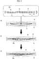
- FIG. 3 shows a flowchart of the joined member assembly method according to the embodiment.
- a base material 20a is inserted into a gap 17 between a first component 15 and a second component 16 which are overlapped (see Fig. 3(A) ).
- a gap amount that is assumed to be generated from shape tolerance during manufacturing is estimated.
- the size and the like of the multilayer structure fabric are selected according to the estimated gap amount for insertion.
- the assumed gap amount also includes a gap amount assumed in advance in a design stage.
- the base material 20a is one before expansion and is easily inserted into the gap 17.
- the gap 17 is filled with a resin such that the base material is impregnated with a resin 18 (see Fig. 3(B) ).
- a spacer for securing necessary clearance for workability may be provided, the base material may be inserted and the resin may be injected thereinto. Accordingly, the base material 20a in the gap 17 is impregnated with the resin 18 and the gap 17 is filled.
- Fig. 3(B) a form during the impregnation of the resin 18 is shown.
- the base material is heated to a predetermined temperature so as to expand in the thickness direction.
- the heating may be carried out simultaneously with the filling of the resin 18 or at several timings before and after the filling.
- the base material can be caused to expand simultaneously with the filling of the resin without being separately heated.
- the base material may be heated after the filling of the resin is completed.
- the predetermined temperature is a temperature at which the high shrinkage yarn 13 can thermally shrink.
- the predetermined temperature may be appropriately set depending on the material of the high shrinkage yarn 13 and the like.
- the high shrinkage yarn 13 shrink by being heated at 60°C to 70°C.
- the warps and wefts having lower thermal shrinkage than the high shrinkage yarn 13 have low shrinkage at the corresponding temperature and thus caused to expand in the thickness direction of the fabric layer 11.
- the heating can be carried out using a heater mat, a hand dryer, an oven, or the like.
- the resin 18 is cured to form a resin 18' (see Fig. 3(C) ).
- a thermosetting resin such as an epoxy resin
- the first component 15 and the second component 16 may be covered and heated by a heater mat or the like so that the resin 18 reaches its curing temperature (for example, 90°C to 120°C) .
- the thermoplastic resin such as PEEK
- cooling is carried out so that the resin 18 reaches its curing temperature.
- the cooling may be air cooling or may be positively carried out using cooling means such as a spot cooler.
- the first component 15 and the second component 16 are fastened with the fastening member.
- a fastening member for example, a rivet, a bolt, or the like is used.
- the base material improves the strength and rigidity required for the joined portion, and by holding the shape, excessive tensile load applied to the fastening member and excessive deformation locally generated in the members to be fastened can be prevented.
- the base material by heating the base material after being inserted into the gap, the base material expands and follows the shape of the gap. Therefore, the base material can be applied to a gap having a complex three-dimensional shape.
- the shape of the base material By causing the shape of the base material to follow the shape of the gap, each of the components is firmly supported between the first component and the second component, and the shape of the joined member can be held.
- the joining surface can be corrected by curing in the gap. Accordingly, the strength and rigidity required for the joined portion can be improved, and excessive tensile load applied to the fastening member and excessive deformation locally generated in the members to be fastened can be prevented.
- steps of measuring the shape of a gap and forming a seam according to the shape through machining are not necessary, and the efficiency of an assembly step can be increased.
- Fig. 4 shows a flowchart of a joined member assembly method according to this embodiment.
- a base material is heated to a predetermined temperature to expand in a thickness direction (see Fig. 4(A)).
- Fig. 4(A) shows a longitudinal section of a base material 20b after the expansion.
- the heating can be carried out using a heater, a hand dryer, an oven, or the like.
- the expanded base material 20b is inserted into the gap 17 between the first component 15 and the second component 16 which are overlapped (mating surface side) (see Figs. 4(A) and Fig. 4(B) ).
- the gap 17 is filled with the resin 18 (see Fig. 4(C) ). Accordingly, the base material 20b in the gap 17 is impregnated with the resin 18 and the gap 17 is filled. In Fig. 4(C) , a form during the impregnation of the resin 18 is shown.
- the resin 18 After completion of the impregnation of the resin 18, the resin 18 is cured in the same manner as in the first embodiment (see Fig. 4(D) ).
- the first component 15 and the second component 16 are fastened with the fastening member.
- the base material since the base material has flexibility even after expansion, filling of the gap with the base material is possible, and the shape of the base material can also follow the shape of the gap. In addition to being able to cope with cases where heating and expansion are difficult after insertion into the gap, a base material having an appropriate size for the amount of a generated gap can be selected.
- the gap is present between the two members, but the gap is not limited thereto.
- the gap may be a space interposed between three or more members.
- the direction in which the high shrinkage yarn is woven may be in the weft direction (the direction perpendicular to the figure) of the fabric layer 11.
- the high shrinkage yarn 13 may have relatively high thermal shrinkage compared to at least the weft.
Landscapes
- Engineering & Computer Science (AREA)
- Mechanical Engineering (AREA)
- Textile Engineering (AREA)
- Chemical & Material Sciences (AREA)
- Composite Materials (AREA)
- Moulding By Coating Moulds (AREA)
- Laminated Bodies (AREA)
- Lining Or Joining Of Plastics Or The Like (AREA)
Abstract
Description
- The present invention relates to a joined member assembly method and a joined member.
- As means for joining two components, there is an adhesive or a fastening member. In PTL 1, two components are joined together by introducing an adhesive between the components.
- However, it is difficult to guarantee the joining strength between the components joined only by the adhesive. Therefore, a fastening member is used for joining components requiring a guarantee of joining strength or components to which an adhesive cannot be applied.
- [PTL 1] Japanese Patent No.
4763196 - Each of members to be joined has shape tolerance due to the influence of shape accuracy up to previous steps. When components with large shape tolerance are overlapped, a gap is generated between mating surfaces (joining surfaces) of the components. When a gap is present between the components, there is concern of fracture due to excessive tensile load applied to a fastening member during fastening, or excessive deformation locally generated in members to be fastened.
- Therefore, when components are assembled together using a fastening member, there is a need to fill a gap between members before a fastening operation.
- For example, the gap between the members is filled by the following steps (see
Figs. 5(A) to 5(C) ). - (A) First, two components (a first component 1 and a second component 2) are overlapped and a shape of the gap between the components is measured.
- (B) Next, a
solid material 3 is machined according to the shape of the gap to form aseam 4. - (C) The
seam 4 is inserted into thegap 5 to fill the gap between the joining surfaces. - The shape of the gap is measured by techniques such as optical surface measurement, gap measurement using a probe or the like, and pouring and solidification of a resin. As the
solid material 3, an aluminum alloy, a resin, or the like is used. - The above-described method is extremely laborious and is thus a labor-intensive method.
- The present invention has been made in view of the above-described circumstances, and an object thereof is to provide a joined member assembly method that makes it possible to increase the efficiency of an assembly step by omitting a step in which a seam is created by machining in accordance with a measured gap shape, and a joined member assembled by the same.
- In order to solve the above-described problem, the joined member assembly method and the joined member of the present invention employ the following means.
- The present invention provides a joined member assembly method including: a step of inserting a base material which is constituted by a multilayer structure fabric that is expandable by heating and is flexible after expansion and a reinforcing material woven into the multilayer structure fabric, into a gap between a plurality of overlapped members; a step of heating the base material so as to cause the base material to expand in a thickness direction; a step of filling the gap with a resin so as to cause the base material to be impregnated with the resin; and a step of curing the resin.
- According to the aspect, the multilayer structure fabric can be caused to expand by heating and follow a complex three-dimensional shape in the gap by the expanding, so that the multilayer structure fabric can be disposed in all the corners of the gap.
- By weaving the reinforcing material, the rigidity of the multilayer structure fabric can be improved. The cured resin and the multilayer structure fabric (base material) into which the reinforcing material is woven function as a seam in the gap. The rigidity for supporting the stress applied to the gap is imparted to the seam by the cured resin and the reinforcing material woven into the multilayer structure fabric. By disposing the base material in the gap, the rigidity is higher than in a seam only made of a resin.
- The combination of the base material that expands to fill the gap and the resin impregnated and cured in the base material has strength and rigidity required for the seam filling the gap between the joined portions and is interposed while the member shapes of the joined portions are maintained. As a result, this leads to prevention of deformation and burden of the fastening member, so that excessive tensile load applied to the fastening member and excessive deformation locally generated in the members to be fastened can be prevented.
- In the aspect of the present invention, the multilayer structure fabric has a fabric layer in which at least two kinds of yarns which are different in thermal shrinkage so as to expand in the thickness direction by being heated are arranged.
- When the fabric layer in which at least two kinds of yarns different in thermal shrinkage are arranged is heated at a predetermined temperature, the yarn having high thermal shrinkage shrinks and correspondingly the yarn having low thermal shrinkage is bent. By utilizing such properties, it is possible to form a multilayer structure fabric which expands in a thickness direction.
- In the aspect of the present invention, after the base material is inserted into the gap, the gap may be impregnated with the resin, the base material may be heated so as to expand in the thickness direction, and the resin may be thereafter cured.
- By heating the base material after being inserted into the gap, the base material follows the shape of the gap while expanding. The base material holds its shape between a plurality of overlapped members and improves the strength and rigidity required for the joined portions. Accordingly, excessive tensile load applied to the fastening member and local deformation generated in the members to be fastened can be prevented.
- In the aspect of the present invention, the base material may be heated so as to expand in the thickness direction, the expanded base material may be inserted into the gap, the base material may be thereafter impregnated with the resin, and the base material may be thereafter cured.
- Since the multilayer structure fabric has flexibility even after expansion, in addition to being able to cope with cases where heating and expansion are difficult after insertion into the gap, a base material having an appropriate size for the amount of a generated gap can be selected.
- The present invention provides a joined member including: a plurality of members arranged in an overlapped state; a seam which is present to fill a gap between the plurality of members, in which the seam includes a base material and a resin, the base material includes a multilayer structure fabric and a reinforcing material woven into the multilayer structure fabric, and the multilayer structure fabric has a fabric layer in which at least two kinds of yarns which are different in thermal shrinkage are arranged, and the fabric layer has a shape in which the yarn having low thermal shrinkage is bent due to a shrinkage stress of the yarn having high thermal shrinkage and expands in the thickness direction.
- According to the present invention, by using the base material having the reinforcing material woven into the self-moldable multilayer structure fabric, a step in which a seam is created by machining in accordance with a measured gap shape is omitted, thereby increasing the efficiency of an assembly step.
-
-
Fig. 1 is a schematic longitudinal sectional view illustrating an example of a multilayer structure fabric. -
Fig. 2 is a partial perspective view illustrating one fabric layer into which a reinforcing material is woven. -
Fig. 3 is a flowchart of a joined member assembly method according to a first embodiment. -
Fig. 4 is a flowchart of a joined member assembly method according to a second embodiment. -
Fig. 5 is a view showing steps of a method in the related art in which a gap is filled with a seam made by machining. - First, a joined member assembled by an assembly method according to this embodiment will be described. The joined member includes a plurality of overlapped members, and a seam which is present to fill a gap between the plurality of members. The joined member further includes a fastening member which fastens the plurality of overlapped members.
- The number of overlapped members may be two or more. Hereinafter, description will be provided on the assumption that the overlapped members include a first component and a second component. The first component and the second component are made of a fiber reinforced composite material, an aluminum alloy, or the like. The fiber reinforced composite material is composed of a matrix and reinforcing fibers. The matrix is a thermosetting resin such as an epoxy resin, a thermoplastic resin such as polyether ether ketone (PEEK), polyether ketone ketone (PEKK), polyphenylene sulfide (PPS), or the like. The reinforcing fiber is carbon fiber, glass fiber, aramid fiber, or the like. The aluminum alloy is in 2000 series, 7000 series, or the like.
- The seam includes a base material and a resin 18'. The base material is constituted by a multilayer structure fabric and a reinforcing material.
-
Fig. 1 is a schematic longitudinal sectional view illustrating an example of the multilayer structure fabric. In the figure,Fig. 1(A) shows amultilayer structure fabric 10a before expansion, andFig. 1(B) shows amultilayer structure fabric 10b after expansion. - The multilayer structure fabric has a plurality of fabric layers 11 laminated and has a mesh-like longitudinal sectional structure. Since
meshes 12 have an elastic structure, the shapes of themultilayer structure fabrics multilayer structure fabrics - The
fabric layer 11 is a fabric composed of at least two kinds of yarns different in thermal shrinkage. The warps and wefts of thefabric layer 11 are made of polyester, nylon, or the like. - In
Fig. 1 , ahigh shrinkage yarn 13 is woven in a warp direction X of thefabric layer 11. Thehigh shrinkage yarn 13 is a fiber yarn for self-molding of the multilayer structure fabric. Thehigh shrinkage yarn 13 has relatively high thermal shrinkage compared to at least awarp 14. The material of thehigh shrinkage yarn 13 is polyester, nylon, polyethylene, acryl, polyurethane, or the like. Thehigh shrinkage yarn 13 is disposed such that thefabric layer 11 expands in a thickness direction T (laminating direction) when thefabric layer 11 is heated at a predetermined temperature. - The reinforcing material (not illustrated) is woven in at least one direction of a weft direction (the direction perpendicular to the figure) and the warp direction X of the
multilayer structure fabrics single fabric layer 11, or may be oriented in one direction in each of the plurality of fabric layers 11. -
Fig. 2 illustrates a single fabric layer into which the reinforcing material is woven. In the figure,Fig. 2(A) shows the fabric layer before heating, andFig. 2(B) is the fabric layer which is caused to expand after the heating, where illustration of the wefts is omitted for simplicity. InFig. 2 , a reinforcingmaterial 21 is woven in three directions including a weft direction Y and directions inclined with respect to the weft direction Y (inclined rightward and inclined leftward). For ease of identification, the reinforcingmaterial 21 oriented in the weft direction Y is shown in black, and the reinforcingmaterial 21 oriented in the inclined directions is shown in white. The reinforcingmaterial 21 oriented in the weft direction Y and the reinforcingmaterial 21 oriented in the inclined directions are woven between high shrinkage yarns present at upper and lower sides in the thickness direction T of each of the fabric layers 11. Thefabric layer 11 illustrated inFig. 2 shrinks in the warp direction (X) by heating, and expands in the thickness direction T. The fabric layer after the expansion has a shape in which the yarn having low thermal shrinkage is bent due to a shrinkage stress of the yarn having high thermal shrinkage and expands in the thickness direction. - The material of the reinforcing material is carbon fiber, aramid fiber, glass fiber, or the like. The reinforcing material content in the
multilayer structure fabrics - The material of the resin may be any material as long as it satisfies all of strength, rigidity, toughness, durability, environmental resistance, and the like required for the application site. For example, the material of the resin is an epoxy resin, polyether ether ketone (PEEK) or the like. The resin is not cured at a temperature at which the
high shrinkage yarn 13 is caused to thermally shrink. Here, "being not cured" allows a curing reaction to an extent that expansion of the base material (the fabric layer 11) is not impeded. The resin may contain a suitable filler (such as chopped materials or powdered materials) to satisfy the required properties. - The fastening member is a rivet, a bolt, or the like. The fastening member fastens a first member and a second member in a state of penetrating through the first member, a joined member, and the second member so as to deliver a load between the members.
- Next, a joined member assembly method according to this embodiment will be described.
Fig. 3 shows a flowchart of the joined member assembly method according to the embodiment. - A
base material 20a is inserted into agap 17 between afirst component 15 and asecond component 16 which are overlapped (seeFig. 3(A) ). Regarding the insertion site, a gap amount that is assumed to be generated from shape tolerance during manufacturing is estimated. The size and the like of the multilayer structure fabric are selected according to the estimated gap amount for insertion. The assumed gap amount also includes a gap amount assumed in advance in a design stage. Thebase material 20a is one before expansion and is easily inserted into thegap 17. - Next, the
gap 17 is filled with a resin such that the base material is impregnated with a resin 18 (seeFig. 3(B) ). At the time of filling of theresin 18, a spacer for securing necessary clearance for workability may be provided, the base material may be inserted and the resin may be injected thereinto. Accordingly, thebase material 20a in thegap 17 is impregnated with theresin 18 and thegap 17 is filled. InFig. 3(B) , a form during the impregnation of theresin 18 is shown. - The base material is heated to a predetermined temperature so as to expand in the thickness direction. The heating may be carried out simultaneously with the filling of the
resin 18 or at several timings before and after the filling. For example, when the temperature of the resin to be filled is equal to or higher than the predetermined temperature, the base material can be caused to expand simultaneously with the filling of the resin without being separately heated. For example, in a case where the temperature of the resin to be filled is lower than the predetermined temperature, the base material may be heated after the filling of the resin is completed. - The predetermined temperature is a temperature at which the
high shrinkage yarn 13 can thermally shrink. The predetermined temperature may be appropriately set depending on the material of thehigh shrinkage yarn 13 and the like. For example, in a case where thehigh shrinkage yarn 13 is made of polyester, thehigh shrinkage yarn 13 shrink by being heated at 60°C to 70°C. The warps and wefts having lower thermal shrinkage than thehigh shrinkage yarn 13 have low shrinkage at the corresponding temperature and thus caused to expand in the thickness direction of thefabric layer 11. The heating can be carried out using a heater mat, a hand dryer, an oven, or the like. - After the
base material 20a is caused to expand, theresin 18 is cured to form a resin 18' (seeFig. 3(C) ). In a case where a thermosetting resin such as an epoxy resin is used as theresin 18, thefirst component 15 and thesecond component 16 may be covered and heated by a heater mat or the like so that theresin 18 reaches its curing temperature (for example, 90°C to 120°C) . In a case where the thermoplastic resin such as PEEK is used as theresin 18, cooling is carried out so that theresin 18 reaches its curing temperature. The cooling may be air cooling or may be positively carried out using cooling means such as a spot cooler. - After the
resin 18 is cured, thefirst component 15 and thesecond component 16 are fastened with the fastening member. For example, a rivet, a bolt, or the like is used. - According to the assembly method of this embodiment, by inserting the multilayer structure fabric into which the reinforcing material is woven into the gap, the base material improves the strength and rigidity required for the joined portion, and by holding the shape, excessive tensile load applied to the fastening member and excessive deformation locally generated in the members to be fastened can be prevented.
- According to the assembly method of this embodiment, by heating the base material after being inserted into the gap, the base material expands and follows the shape of the gap. Therefore, the base material can be applied to a gap having a complex three-dimensional shape. By causing the shape of the base material to follow the shape of the gap, each of the components is firmly supported between the first component and the second component, and the shape of the joined member can be held. The joining surface can be corrected by curing in the gap. Accordingly, the strength and rigidity required for the joined portion can be improved, and excessive tensile load applied to the fastening member and excessive deformation locally generated in the members to be fastened can be prevented.
- According to the assembly method of this embodiment, steps of measuring the shape of a gap and forming a seam according to the shape through machining are not necessary, and the efficiency of an assembly step can be increased.
- The configuration of a joined member assembled by an assembly method according to this embodiment is the same as that of the first embodiment. The assembly method according to this embodiment is different from the first embodiment in the timing at which the base material is caused to expand.
Fig. 4 shows a flowchart of a joined member assembly method according to this embodiment. - A base material is heated to a predetermined temperature to expand in a thickness direction (see
Fig. 4(A)). Fig. 4(A) shows a longitudinal section of abase material 20b after the expansion. The heating can be carried out using a heater, a hand dryer, an oven, or the like. - The expanded
base material 20b is inserted into thegap 17 between thefirst component 15 and thesecond component 16 which are overlapped (mating surface side) (seeFigs. 4(A) and Fig. 4(B) ). - The
gap 17 is filled with the resin 18 (seeFig. 4(C) ). Accordingly, thebase material 20b in thegap 17 is impregnated with theresin 18 and thegap 17 is filled. InFig. 4(C) , a form during the impregnation of theresin 18 is shown. - After completion of the impregnation of the
resin 18, theresin 18 is cured in the same manner as in the first embodiment (seeFig. 4(D) ). - As in the first embodiment, the
first component 15 and thesecond component 16 are fastened with the fastening member. - In this embodiment, since the base material has flexibility even after expansion, filling of the gap with the base material is possible, and the shape of the base material can also follow the shape of the gap. In addition to being able to cope with cases where heating and expansion are difficult after insertion into the gap, a base material having an appropriate size for the amount of a generated gap can be selected.
- In the first embodiment and the second embodiment described above, the gap is present between the two members, but the gap is not limited thereto. For example, the gap may be a space interposed between three or more members.
- The direction in which the high shrinkage yarn is woven may be in the weft direction (the direction perpendicular to the figure) of the
fabric layer 11. In this case, thehigh shrinkage yarn 13 may have relatively high thermal shrinkage compared to at least the weft. -
- 1, 15: first component
- 2, 16: second component
- 3: solid material
- 4: seam (generated from solid material by machining)
- 5, 17: gap (gap)
- 10a: multilayer structure fabric (before expansion)
- 10b: multilayer structure fabric (after expansion)
- 11: fabric layer
- 12: mesh
- 13: high shrinkage yarn
- 14: warp (low shrinkage yarn)
- 18: resin (before curing)
- 18': resin (after curing)
- 20a: base material (before expansion)
- 20b: base material (after expansion)
- 21: reinforcing material
Claims (5)
- A joined member assembly method comprising:a step of inserting a base material which is constituted by a multilayer structure fabric that is expandable by heating and is flexible after expansion and a reinforcing material woven into the multilayer structure fabric, into a gap between a plurality of overlapped members;a step of heating the base material so as to cause the base material to expand in a thickness direction;a step of filling the gap with a resin so as to cause the base material to be impregnated with the resin; anda step of curing the resin.
- The joined member assembly method according to claim 1,
wherein the multilayer structure fabric has a fabric layer in which at least two kinds of yarns which are different in thermal shrinkage so as to expand in the thickness direction by being heated are arranged. - The joined member assembly method according to claim 1 or 2,
wherein, after the base material is inserted into the gap, the gap is impregnated with the resin, the base material is heated so as to expand in the thickness direction, and the resin is thereafter cured. - The joined member assembly method according to claim 1 or 2,
wherein the base material is heated so as to expand in the thickness direction, the expanded base material is inserted into the gap, the base material is thereafter impregnated with the resin, and the resin is thereafter cured. - A joined member comprising:a plurality of members arranged in an overlapped state;a seam which is present to fill a gap between the plurality of members,wherein the seam includes a base material and a resin,the base material includes a multilayer structure fabric and a reinforcing material woven into the multilayer structure fabric, andthe multilayer structure fabric has a fabric layer in which at least two kinds of yarns which are different in thermal shrinkage are arranged, and the fabric layer has a shape in which the yarn having low thermal shrinkage is bent due to a shrinkage stress of the yarn having high thermal shrinkage and expands in a thickness direction.
Applications Claiming Priority (2)
| Application Number | Priority Date | Filing Date | Title |
|---|---|---|---|
| JP2016139314A JP6642918B2 (en) | 2016-07-14 | 2016-07-14 | Method of assembling joining member and joining member |
| PCT/JP2017/024267 WO2018012328A1 (en) | 2016-07-14 | 2017-06-30 | Joined member assembly method and joined member |
Publications (2)
| Publication Number | Publication Date |
|---|---|
| EP3427932A1 true EP3427932A1 (en) | 2019-01-16 |
| EP3427932A4 EP3427932A4 (en) | 2019-06-19 |
Family
ID=60951761
Family Applications (1)
| Application Number | Title | Priority Date | Filing Date |
|---|---|---|---|
| EP17827458.5A Withdrawn EP3427932A4 (en) | 2016-07-14 | 2017-06-30 | METHOD FOR ASSEMBLING ASSEMBLED ELEMENT AND ASSEMBLED ELEMENT |
Country Status (6)
| Country | Link |
|---|---|
| US (1) | US11318710B2 (en) |
| EP (1) | EP3427932A4 (en) |
| JP (1) | JP6642918B2 (en) |
| CN (1) | CN109070497B (en) |
| CA (1) | CA3026038C (en) |
| WO (1) | WO2018012328A1 (en) |
Cited By (1)
| Publication number | Priority date | Publication date | Assignee | Title |
|---|---|---|---|---|
| CN113443118A (en) * | 2021-09-01 | 2021-09-28 | 成都飞机工业(集团)有限责任公司 | Aircraft component, filling structure for aircraft component process stiffening and installation method |
Families Citing this family (1)
| Publication number | Priority date | Publication date | Assignee | Title |
|---|---|---|---|---|
| EP3560694B1 (en) | 2016-12-22 | 2023-03-01 | Toray Industries, Inc. | Production method for composite structures and production method for integrated composite structures |
Family Cites Families (32)
| Publication number | Priority date | Publication date | Assignee | Title |
|---|---|---|---|---|
| US2909784A (en) * | 1957-06-19 | 1959-10-27 | Hexcel Products Inc | Stitched multi-ply cellular structure |
| US3602964A (en) * | 1969-04-10 | 1971-09-07 | Collins & Aikman Corp | Dual wall fabric with expandable height between layers |
| US3811480A (en) * | 1970-06-15 | 1974-05-21 | Arova Schaffhausen Ag | Multi-layer fabric |
| US3769142A (en) * | 1970-12-04 | 1973-10-30 | Mc Donnell Douglas Corp | Non-woven locked ply composite structure |
| US4038440A (en) * | 1972-01-24 | 1977-07-26 | Avco Corporation | Three dimensional fabric material |
| JPS5239473B2 (en) * | 1972-05-19 | 1977-10-05 | ||
| DE2529185C2 (en) * | 1975-07-01 | 1986-12-11 | Erich Dipl.-Volksw. 5300 Bonn Wintermantel | Component as a substructure element, reinforcement element or the like |
| EP0134864A3 (en) | 1983-09-16 | 1986-10-01 | Walter A. Plummer Jr. | Braided sleeving |
| US4741087A (en) | 1983-09-16 | 1988-05-03 | Plummer Jr Walter A | Method of making pre-expanded braided sleeving |
| US4571355A (en) * | 1984-11-28 | 1986-02-18 | The Boeing Company | Fiber reinforced resin composites formed of basic ply blankets |
| JPH0723571B2 (en) * | 1985-01-30 | 1995-03-15 | 旭化成工業株式会社 | Multi-layer fabric |
| JPH02200872A (en) * | 1988-10-24 | 1990-08-09 | Asahi Chem Ind Co Ltd | Woven fabric elastic body and production thereof |
| US5211967A (en) * | 1991-03-15 | 1993-05-18 | Kabushiki Kaisha Toyoda Jidoshokki Seisakusho | Three-dimensional fabric and method of producing the same |
| JPH0694057A (en) * | 1992-09-09 | 1994-04-05 | Nissin Kogyo Kk | Brake squeal prevention material |
| JPH06128837A (en) | 1992-10-19 | 1994-05-10 | Teijin Ltd | Three-dimensional structure cloth and manufacturing method thereof |
| JP3582602B2 (en) * | 1993-04-05 | 2004-10-27 | 東洋紡績株式会社 | Cryogenic container |
| ES2154710T3 (en) * | 1994-12-16 | 2001-04-16 | Hoechst Trevira Gmbh & Co Kg | HYBRID THREAD AND DEFORMABLE TEXTILE MATERIAL PERMANENTLY SHRINKABLE AND SHRINKED, MANUFACTURED FROM THE SAME, ITS MANUFACTURE AND USE. |
| GB9921784D0 (en) | 1999-09-16 | 1999-11-17 | British Aerospace | A method of producing a joint |
| JP2001270041A (en) * | 2000-03-23 | 2001-10-02 | Spirulina Biological Lab Ltd | Method for manufacturing composite material |
| US7048985B2 (en) * | 2001-07-23 | 2006-05-23 | Vrac, Llc | Three-dimensional spacer fabric resin infusion media and reinforcing composite lamina |
| FR2836690B1 (en) * | 2002-03-04 | 2004-08-27 | Eads Launch Vehicles | PROCESS FOR THE PRODUCTION OF A DOUBLE-WALL THERMOSTRUCTURAL COMPOSITE MONOLITHIC PIECE AND PART OBTAINED |
| JP2003276023A (en) * | 2002-03-26 | 2003-09-30 | Asahi Fiber Glass Co Ltd | Composite wire, swirl mat and swirl sheet |
| JP2005279990A (en) * | 2004-03-29 | 2005-10-13 | Toyota Boshoku Corp | Laser welding method and laser welding structure |
| US7258828B2 (en) * | 2004-09-03 | 2007-08-21 | Lockheed Martin Corporation | Infusion joining of composite structures |
| JP4362465B2 (en) | 2005-10-06 | 2009-11-11 | 福井県 | Cushion structure |
| US9797076B2 (en) * | 2012-03-23 | 2017-10-24 | Nandan Khokar | 3D fabric and a method and apparatus for producing such a 3D fabric |
| BE1020722A3 (en) * | 2012-06-01 | 2014-04-01 | Unilin Bvba | PANEL FOR FORMING A FLOOR COVERING AND METHOD FOR MANUFACTURING SUCH PANELS. |
| DK2762297T3 (en) * | 2013-02-05 | 2019-01-07 | Siemens Ag | Pressure sensitive power distribution medium for VARTM |
| US9527248B2 (en) * | 2013-03-15 | 2016-12-27 | Seriforge Inc. | Systems for three-dimensional weaving of composite preforms and products with varying cross-sectional topology |
| CN105658896A (en) * | 2013-08-29 | 2016-06-08 | 卫柏思有限公司 | Unit cell, shade joining the unit cell, and shade assembly including the shade |
| JP2016065164A (en) | 2014-09-25 | 2016-04-28 | 京セラケミカル株式会社 | Heat-expandable adhesive sheet and method for bonding components |
| JP7361553B2 (en) | 2019-06-25 | 2023-10-16 | 立川ブラインド工業株式会社 | Detection device and shielding device |
-
2016
- 2016-07-14 JP JP2016139314A patent/JP6642918B2/en active Active
-
2017
- 2017-06-30 CN CN201780022744.5A patent/CN109070497B/en not_active Expired - Fee Related
- 2017-06-30 US US16/305,055 patent/US11318710B2/en active Active
- 2017-06-30 WO PCT/JP2017/024267 patent/WO2018012328A1/en not_active Ceased
- 2017-06-30 EP EP17827458.5A patent/EP3427932A4/en not_active Withdrawn
- 2017-06-30 CA CA3026038A patent/CA3026038C/en not_active Expired - Fee Related
Cited By (2)
| Publication number | Priority date | Publication date | Assignee | Title |
|---|---|---|---|---|
| CN113443118A (en) * | 2021-09-01 | 2021-09-28 | 成都飞机工业(集团)有限责任公司 | Aircraft component, filling structure for aircraft component process stiffening and installation method |
| CN113443118B (en) * | 2021-09-01 | 2022-01-25 | 成都飞机工业(集团)有限责任公司 | Aircraft component, filling structure for aircraft component process stiffening and installation method |
Also Published As
| Publication number | Publication date |
|---|---|
| JP2018008440A (en) | 2018-01-18 |
| CN109070497A (en) | 2018-12-21 |
| US11318710B2 (en) | 2022-05-03 |
| CA3026038C (en) | 2020-11-03 |
| CN109070497B (en) | 2021-01-22 |
| US20200282696A1 (en) | 2020-09-10 |
| WO2018012328A1 (en) | 2018-01-18 |
| CA3026038A1 (en) | 2018-01-18 |
| JP6642918B2 (en) | 2020-02-12 |
| EP3427932A4 (en) | 2019-06-19 |
Similar Documents
| Publication | Publication Date | Title |
|---|---|---|
| CN111344486B (en) | Improvements related to structural components of wind turbine blades | |
| US8911580B2 (en) | Method for producing a structural component | |
| Tong et al. | 3D fibre reinforced polymer composites | |
| JP4944790B2 (en) | Reinforced panel woven in three dimensions | |
| KR101538345B1 (en) | Method for weaving closed structures with intersecting walls | |
| CN106132696B (en) | Composite structure and manufacturing method thereof | |
| US9550340B2 (en) | Composite material part comprising fixing means | |
| JP5303277B2 (en) | Corner fitting using fiber movement | |
| JP5436468B2 (en) | Manufacturing method of sandwich panel having insert structure | |
| CA3026038C (en) | Joined member assembly method and joined member | |
| CN108430756A (en) | Composite grid structure | |
| US8894013B2 (en) | Aircraft assembly and method for producing an aircraft assembly | |
| US20140186574A1 (en) | Method for producing and connecting fibre-reinforced components and aircraft or spacecraft | |
| US8640428B2 (en) | Strength enhancing insert assemblies | |
| JP2018008440A5 (en) | ||
| EP2707606B1 (en) | Connecting device, assembly and method for manufacturing an assembly | |
| JP2015080944A (en) | Fiber-reinforced resin | |
| JP6604286B2 (en) | Multilayer woven fabric and sandwich fiber reinforced composite for sandwich construction | |
| Daghia | Active fibre-reinforced composites with embedded shape memory alloys | |
| JP4837897B2 (en) | Fiber reinforced resin and method for producing the same | |
| EP3798137A1 (en) | Pipe structure and truss structure, and artificial satellite using such structures | |
| EP2781345B1 (en) | Method and system for producing composite structures | |
| JP2014058090A (en) | Fiber-reinforced preform and fiber-reinforced composite material | |
| CA3087532C (en) | Fiber reinforced materials with improved fatigue performance | |
| WO2017187920A1 (en) | Joined member assembly method and joined member |
Legal Events
| Date | Code | Title | Description |
|---|---|---|---|
| STAA | Information on the status of an ep patent application or granted ep patent |
Free format text: STATUS: THE INTERNATIONAL PUBLICATION HAS BEEN MADE |
|
| PUAI | Public reference made under article 153(3) epc to a published international application that has entered the european phase |
Free format text: ORIGINAL CODE: 0009012 |
|
| STAA | Information on the status of an ep patent application or granted ep patent |
Free format text: STATUS: REQUEST FOR EXAMINATION WAS MADE |
|
| 17P | Request for examination filed |
Effective date: 20181012 |
|
| AK | Designated contracting states |
Kind code of ref document: A1 Designated state(s): AL AT BE BG CH CY CZ DE DK EE ES FI FR GB GR HR HU IE IS IT LI LT LU LV MC MK MT NL NO PL PT RO RS SE SI SK SM TR |
|
| AX | Request for extension of the european patent |
Extension state: BA ME |
|
| A4 | Supplementary search report drawn up and despatched |
Effective date: 20190522 |
|
| RIC1 | Information provided on ipc code assigned before grant |
Ipc: B32B 7/028 20190101ALI20190515BHEP Ipc: B32B 15/14 20060101ALI20190515BHEP Ipc: B32B 5/06 20060101ALI20190515BHEP Ipc: B29K 105/08 20060101ALI20190515BHEP Ipc: B32B 5/02 20060101ALI20190515BHEP Ipc: B64C 1/00 20060101ALI20190515BHEP Ipc: B32B 5/26 20060101ALI20190515BHEP Ipc: B32B 5/10 20060101ALI20190515BHEP Ipc: B32B 5/08 20060101ALI20190515BHEP Ipc: B32B 5/04 20060101ALI20190515BHEP Ipc: B32B 7/02 20190101ALI20190515BHEP Ipc: B29C 65/70 20060101ALI20190515BHEP Ipc: B64F 5/10 20170101ALI20190515BHEP Ipc: B29C 70/40 20060101AFI20190515BHEP Ipc: B32B 7/08 20190101ALI20190515BHEP Ipc: B29K 101/10 20060101ALI20190515BHEP Ipc: B29C 70/10 20060101ALI20190515BHEP |
|
| DAV | Request for validation of the european patent (deleted) | ||
| DAX | Request for extension of the european patent (deleted) | ||
| STAA | Information on the status of an ep patent application or granted ep patent |
Free format text: STATUS: THE APPLICATION HAS BEEN WITHDRAWN |
|
| GRAP | Despatch of communication of intention to grant a patent |
Free format text: ORIGINAL CODE: EPIDOSNIGR1 |
|
| 18W | Application withdrawn |
Effective date: 20210728 |
|
| INTG | Intention to grant announced |
Effective date: 20210803 |
|
| RIN1 | Information on inventor provided before grant (corrected) |
Inventor name: MORISHIMA, SHUNICHI Inventor name: KOZASA, TOSHIO Inventor name: HATANO, MASATAKE Inventor name: KISHIMOTO, KAZUAKI Inventor name: TAKEUCHI, YUKIO Inventor name: MATSUHASHI, MASAHIKO |