EP3427878A1 - End mill machining device, cam device, nc program, and machining method - Google Patents
End mill machining device, cam device, nc program, and machining method Download PDFInfo
- Publication number
- EP3427878A1 EP3427878A1 EP17763011.8A EP17763011A EP3427878A1 EP 3427878 A1 EP3427878 A1 EP 3427878A1 EP 17763011 A EP17763011 A EP 17763011A EP 3427878 A1 EP3427878 A1 EP 3427878A1
- Authority
- EP
- European Patent Office
- Prior art keywords
- end mill
- machining
- workpiece
- contact angle
- machining apparatus
- Prior art date
- Legal status (The legal status is an assumption and is not a legal conclusion. Google has not performed a legal analysis and makes no representation as to the accuracy of the status listed.)
- Withdrawn
Links
Images



Classifications
-
- B—PERFORMING OPERATIONS; TRANSPORTING
- B23—MACHINE TOOLS; METAL-WORKING NOT OTHERWISE PROVIDED FOR
- B23C—MILLING
- B23C5/00—Milling-cutters
- B23C5/02—Milling-cutters characterised by the shape of the cutter
- B23C5/10—Shank-type cutters, i.e. with an integral shaft
-
- B—PERFORMING OPERATIONS; TRANSPORTING
- B23—MACHINE TOOLS; METAL-WORKING NOT OTHERWISE PROVIDED FOR
- B23C—MILLING
- B23C3/00—Milling particular work; Special milling operations; Machines therefor
-
- B—PERFORMING OPERATIONS; TRANSPORTING
- B23—MACHINE TOOLS; METAL-WORKING NOT OTHERWISE PROVIDED FOR
- B23C—MILLING
- B23C3/00—Milling particular work; Special milling operations; Machines therefor
- B23C3/28—Grooving workpieces
- B23C3/30—Milling straight grooves, e.g. keyways
-
- B—PERFORMING OPERATIONS; TRANSPORTING
- B23—MACHINE TOOLS; METAL-WORKING NOT OTHERWISE PROVIDED FOR
- B23Q—DETAILS, COMPONENTS, OR ACCESSORIES FOR MACHINE TOOLS, e.g. ARRANGEMENTS FOR COPYING OR CONTROLLING; MACHINE TOOLS IN GENERAL CHARACTERISED BY THE CONSTRUCTION OF PARTICULAR DETAILS OR COMPONENTS; COMBINATIONS OR ASSOCIATIONS OF METAL-WORKING MACHINES, NOT DIRECTED TO A PARTICULAR RESULT
- B23Q15/00—Automatic control or regulation of feed movement, cutting velocity or position of tool or work
- B23Q15/007—Automatic control or regulation of feed movement, cutting velocity or position of tool or work while the tool acts upon the workpiece
- B23Q15/12—Adaptive control, i.e. adjusting itself to have a performance which is optimum according to a preassigned criterion
-
- G—PHYSICS
- G05—CONTROLLING; REGULATING
- G05B—CONTROL OR REGULATING SYSTEMS IN GENERAL; FUNCTIONAL ELEMENTS OF SUCH SYSTEMS; MONITORING OR TESTING ARRANGEMENTS FOR SUCH SYSTEMS OR ELEMENTS
- G05B19/00—Program-control systems
- G05B19/02—Program-control systems electric
- G05B19/18—Numerical control [NC], i.e. automatically operating machines, in particular machine tools, e.g. in a manufacturing environment, so as to execute positioning, movement or co-ordinated operations by means of program data in numerical form
- G05B19/404—Numerical control [NC], i.e. automatically operating machines, in particular machine tools, e.g. in a manufacturing environment, so as to execute positioning, movement or co-ordinated operations by means of program data in numerical form characterised by control arrangements for compensation, e.g. for backlash, overshoot, tool offset, tool wear, temperature, machine construction errors, load, inertia
-
- G—PHYSICS
- G05—CONTROLLING; REGULATING
- G05B—CONTROL OR REGULATING SYSTEMS IN GENERAL; FUNCTIONAL ELEMENTS OF SUCH SYSTEMS; MONITORING OR TESTING ARRANGEMENTS FOR SUCH SYSTEMS OR ELEMENTS
- G05B19/00—Program-control systems
- G05B19/02—Program-control systems electric
- G05B19/18—Numerical control [NC], i.e. automatically operating machines, in particular machine tools, e.g. in a manufacturing environment, so as to execute positioning, movement or co-ordinated operations by means of program data in numerical form
- G05B19/4093—Numerical control [NC], i.e. automatically operating machines, in particular machine tools, e.g. in a manufacturing environment, so as to execute positioning, movement or co-ordinated operations by means of program data in numerical form characterised by part programming, e.g. entry of geometrical information as taken from a technical drawing, combining this with machining and material information to obtain control information, named part program, for the NC machine
-
- G—PHYSICS
- G05—CONTROLLING; REGULATING
- G05B—CONTROL OR REGULATING SYSTEMS IN GENERAL; FUNCTIONAL ELEMENTS OF SUCH SYSTEMS; MONITORING OR TESTING ARRANGEMENTS FOR SUCH SYSTEMS OR ELEMENTS
- G05B19/00—Program-control systems
- G05B19/02—Program-control systems electric
- G05B19/18—Numerical control [NC], i.e. automatically operating machines, in particular machine tools, e.g. in a manufacturing environment, so as to execute positioning, movement or co-ordinated operations by means of program data in numerical form
- G05B19/4155—Numerical control [NC], i.e. automatically operating machines, in particular machine tools, e.g. in a manufacturing environment, so as to execute positioning, movement or co-ordinated operations by means of program data in numerical form characterised by program execution, i.e. part program or machine function execution, e.g. selection of a program
-
- B—PERFORMING OPERATIONS; TRANSPORTING
- B23—MACHINE TOOLS; METAL-WORKING NOT OTHERWISE PROVIDED FOR
- B23C—MILLING
- B23C2210/00—Details of milling cutters
- B23C2210/28—Arrangement of teeth
- B23C2210/282—Unequal angles between the cutting edges, i.e. cutting edges unequally spaced in the circumferential direction
-
- B—PERFORMING OPERATIONS; TRANSPORTING
- B23—MACHINE TOOLS; METAL-WORKING NOT OTHERWISE PROVIDED FOR
- B23C—MILLING
- B23C2250/00—Compensating adverse effects during milling
- B23C2250/16—Damping vibrations
-
- G—PHYSICS
- G05—CONTROLLING; REGULATING
- G05B—CONTROL OR REGULATING SYSTEMS IN GENERAL; FUNCTIONAL ELEMENTS OF SUCH SYSTEMS; MONITORING OR TESTING ARRANGEMENTS FOR SUCH SYSTEMS OR ELEMENTS
- G05B2219/00—Program-control systems
- G05B2219/30—Nc systems
- G05B2219/35—Nc in input of data, input till input file format
- G05B2219/35101—CC cutter contact path
-
- G—PHYSICS
- G05—CONTROLLING; REGULATING
- G05B—CONTROL OR REGULATING SYSTEMS IN GENERAL; FUNCTIONAL ELEMENTS OF SUCH SYSTEMS; MONITORING OR TESTING ARRANGEMENTS FOR SUCH SYSTEMS OR ELEMENTS
- G05B2219/00—Program-control systems
- G05B2219/30—Nc systems
- G05B2219/37—Measurements
- G05B2219/37355—Cutting, milling, machining force
Definitions
- the technique of the present specification relates to an end mill machining apparatus, a CAM apparatus, an NC program, and a machining method. More specifically, the technique relates to an end mill machining apparatus, a CAM apparatus, NC program, and a machining method which suppress vibrations during machining.
- Cutting is frequently used in processes of manufacturing industrial products. For example, cutting is used for direct machining of products and machining of dies. When such cutting is performed, chatter vibrations may be generated on a tool. Chatter vibrations cause a deterioration in the shape of a finished surface or breakage of the tool.
- Chatter vibrations include two types of vibrations; i.e., forced vibration and self-excited vibration.
- Forced vibration is a vibration which is generated when some forced causal vibration is amplified by the vibration characteristic of a machine. For example, intermittent cutting force generated during end milling or the like causes forced vibration. However, in some cases, the term "chatter vibration" does not encompass forced vibration.
- Self-excited vibration is a vibration which is generated when a vibration generated in a cutting process grows (i.e., is amplified) because of a presence of a closed loop that feeds back the generated vibration.
- self-excited vibration Major types include a regenerative type self-excited vibration and a mode-coupling type self-excited vibration.
- Regenerative self-excited vibration is generated, for example, when a vibration generated during cutting in a previous rotation or cutting by a preceding tooth has remained as an undulation of the machined surface, the uncut chip thickness fluctuates in time due to the remaining shape and a vibration at the present point.
- Mode-coupling self-excited vibration is generated, for example, when vibration modes in two directions have resonance frequencies close to each other and the vibrations in the two directions are coupled.
- chatter vibrations are collectively shown in the following Table 1.
- Table 1 (a) forced vibration (b) self-excited vibration (b-1) regenerative self-excited vibration (b-2) mode-coupling self-excited vibration
- Patent Document 1 discloses an unequally divided end mill which has an odd number of cutting teeth and in which dividing angles different from one another are provided for the cutting teeth.
- Patent Document 1 Japanese Patent Application Laid-Open ( kokai ) No. 2000-714
- the technique disclosed in the present specification has been accomplished so as to solve the above-described problem of the conventional technique. Its objective is to provide an end mill machining apparatus, a CAM apparatus, an NC program, and a machining method which suppress regenerative self-excited vibration and mode-coupling self-excited vibration.
- An end mill machining apparatus comprises an end mill, and a control section for controlling the end mill.
- the ratio of a protrusion length of the end mill to a diameter of the end mill falls within a range of 5 to 50.
- the end mill is a variable pitch, uniform helix type or a variable helix type.
- the control section controls a contact angle between the end mill and the workpiece during machining to a critical contact angle ⁇ lim or smaller.
- an end mill machining apparatus a CAM apparatus, an NC program, and a machining method which suppress regenerative self-excited vibration and mode-coupling self-excited vibration.
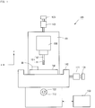
- FIG. 1 is a view showing an end mill machining apparatus 100 of the present embodiment.
- the end mill machining apparatus 100 includes an end mill 10, a machining unit 130, a body 101, an X-axis motor 111, a Y-axis motor 112, a Z-axis motor 113, an X-axis sensor 121, a Y-axis sensor 122, a Z-axis sensor 123, an X-axis feed table 141, a Y-axis feed table 142, and a control section 150.
- the end mill 10 is a tool for machining a workpiece which is to be machined actually.
- the end mill 10 has a tooth portion 11 for machining the workpiece, and a non-tooth portion 12 which is formed integrally with the tooth portion 11 and which has no cutting teeth.
- the tooth portion 11 is located on the distal end side with respect to the non-tooth portion 12.
- the machining unit 130 supports a spindle which holds the end mill 10.
- the machining unit 130 can be moved in a Z-axis direction by the Z-axis motor 113.
- the X-axis feed table 141 is a table on which a workpiece M1 is disposed.
- the X-axis feed table 141 can be moved in an X-axis direction by the X-axis motor 111.
- the Y-axis feed table 142 can be moved in a Y-axis direction by the Y-axis motor 112. Therefore, the X-axis feed table 141 can be moved in the X-axis direction and the Y-axis direction.
- the X-axis motor 111 is used to move the X-axis feed table 141 in the X-axis direction.
- the Y-axis motor 112 is used to move the Y-axis feed table 142 in the Y-axis direction.
- the Z-axis motor 113 is used to move the machining unit 130 in the Z-axis direction.
- FIG. 2 is a sectional view schematically showing the internal structure of the machining unit 130.
- the machining unit 130 includes a tool holder 131, a rotation spindle 132, and a spindle bearing 133, as well as the end mill 10.
- the tool holder 131 is a tool holding portion which grasps the end mill 10 and couples the end mill 10 with the rotation spindle 132.
- the tool holder 131 has a recess 131a.
- the end mill 10 is held in a state in which it is received by the recess 131a.
- a holding mechanism of the tool holder 131 for holding the end mill 10 is the same as that used in the conventional technique.
- the tool holder 131 is coupled with the rotation spindle 132 and is rotationally driven by the rotation spindle 132. Namely, the tool holder 131 rotates together with the end mill 10.
- the spindle bearing 133 is one of bearings for supporting the rotation spindle 132. Therefore, the spindle bearing 133 supports all rotation members (from the rotation spindle 132 to the end mill 10) which rotate together.
- the control section 150 controls respective portions of the end mill machining apparatus 100.
- the control section 150 controls the end mill 10 to depict a trochoid locus on the workpiece M1.
- the end mill 10 is very thin and long as compared with conventional end mills.
- the ratio of the protrusion length L of the end mill 10 to the diameter D of the end mill 10; i.e., the L/D ratio, is 5 to 50.
- the machining method of the present embodiment is suitable for the case where the ratio of the protrusion length L of the end mill 10 to the diameter D of the end mill 10; i.e., the L/D ratio, is 10 to 50.
- the end mill 10 is of a variable helix type.
- the tooth portion 11 of the end mill 10 has, for example, two cutting teeth (blades).
- the number of the cutting teeth of the tooth portion 11 may be three or more.
- FIG. 3 shows the control system of the present embodiment.
- the control section 150 includes an NC program storage section 161, a program analysis section 162, a motor control section 170, and other control sections 180.
- the NC program storage section 161 stores an NC program.
- the program analysis section 162 analyzes the NC program stored in the NC program storage section 161 and executes the program.
- the motor control section 170 controls the motors.
- the motor control section 170 includes an X-axis control section 171, a Y-axis control section 172, a Z-axis control section 173, and a spindle control section 174.
- the X-axis control section 171 controls the position of the workpiece M1 in the X-axis direction.
- position refers to the relative position of the end mill 10 with respect to the workpiece M1.
- the Y-axis control section 172 controls the position of the workpiece M1 in the Y-axis direction.
- the Z-axis control section 173 controls the position of the workpiece M1 in the Z-axis direction.
- the spindle control section 174 controls rotation of the spindle supporting the end mill 10.
- the X-axis sensor 121 measures the position of the workpiece M1 in the X-axis direction.
- the Y-axis sensor 122 measures the position of the workpiece M1 in the Y-axis direction.
- the Z-axis sensor 123 measures the position of the workpiece M1 in the Z-axis direction.
- the X-axis motor 111 changes the position of the workpiece M1 in the X-axis direction.
- the Y-axis motor 112 changes the position of the workpiece M1 in the Y-axis direction.
- the Z-axis motor 113 changes the position of the workpiece M1 in the Z-axis direction.
- the Z-axis motor 113 may change the position in the Z-axis direction of the machining unit 130 having the end mill 10.
- the spindle sensor 124 detects rotation of the spindle.
- the spindle motor 114 rotates the spindle.
- An input receiving section 191 receives instructions entered by an operator.
- the input receiving section 191 can receive the input of information representing the shape of the end mill 10 and information representing the material of the workpiece M1.
- Other portions 190 refer to structural portions of the end mill machining apparatus 100 other than the above-described portions.
- control section 150 controls the various portions of the end mill machining apparatus 100. As will be described later, the control section 150 controls the end mill 10 to depict a trochoid locus on the workpiece M1.
- the X-axis control section 171 and the Y-axis control section 172 control the X-axis motor 111 and the Y-axis motor 112, respectively, such that the end mill 10 depicts a trochoid locus on the workpiece M1.
- the control section 150 controls machining on the basis of the NC program.
- the control section 150 of the end mill machining apparatus 100 controls the end mill 10 to depict a trochoid locus on the workpiece M1.
- FIG. 4 is an illustration showing a trochoid locus depicted by the end mill 10. Since trochoid machining is performed, a contact angle, which is an angular range within which the end mill 10 is in contact with the workpiece M1 during machining, can be rendered smaller. Therefore, the trochoid machining can suppress (b-2) mode-coupling self-excited vibration.
- FIG. 5 is an illustration showing the contact angle of the end mill 10 with respect to the workpiece M1 in the case where the end mill 10 is moved to depict a trochoid locus.
- the term "contact angle” used herein refers to an angular range within which the tooth portion 11 of the end mill 10 is in contact with the workpiece M1.
- a critical contact angle ⁇ lim refers to the maximum contact angle at which no mode-coupling self-excited vibration is generated. This critical contact angle ⁇ lim will be described later.
- variable lead end mill 10 As a result of use of the variable lead end mill 10, (b-1) regenerative self-excited vibration can be suppressed.
- both (b-1) regenerative self-excited vibration and (b-2) mode-coupling self-excited vibration can be suppressed when (1) the variable lead end mill 10 is used, (2) the workpiece M1 is machined by moving the end mill 10 to depict a trochoid locus, and (3) the workpiece M1 is machined with a contact angle equal to or smaller than the critical contact angle ⁇ lim . Therefore, even when a large axial depth of cut P1 (see FIG. 2 ) is employed, stable machining can be performed.
- control section 150 renders the angle of contact between the end mill 10 and the workpiece M1 during machining equal to or smaller than the critical contact angle ⁇ lim .
- the axial depth of cut P1 of the end mill 10 is set to fall with the range of 7 mm to 9 mm. Therefore, as will be described later, productivity becomes 10 times or more.
- the axial depth of cut P1 is considered to depend on the diameter D of the end mill 10. The greater the diameter D of the end mill 10, the greater the value to which the axial depth of cut P1 can be set. Therefore, the axial depth of cut P1 can be set to a value which is equal to or greater than 1/6 of the diameter D of the end mill 10.
- the contact angle is an angle range over which the tooth portion 11 of the end mill 10 is in contact with the workpiece M1.
- the critical contact angle ⁇ lim is the maximum contact angle at which no mode-coupling self-excited vibration is generated. Namely, no self-excited vibration is generated in the case where trochoid machining is performed in a state in which the end mill 10 is in contact with the workpiece M1 over a contact angle equal to or smaller than the critical contact angle ⁇ lim . Self-excited vibration may be generated in the case where trochoid machining is performed in a state in which the end mill 10 is in contact with the workpiece M1 over a contact angle greater than the critical contact angle ⁇ lim .
- the workpiece M1 and the shape of the cutting teeth of the end mill 10 determine the critical contact angle ⁇ lim . Therefore, when information representing the shape of the end mill 10 and information representing the material of the workpiece M1 are input to the end mill machining apparatus 100, the end mill machining apparatus 100 can perform machining while suppressing mode-coupling self-excited vibration.
- a 0 N 2 ⁇ ⁇ ⁇ st ⁇ ed
- ⁇ 0 yy N 4 ⁇ ⁇ cos 2 ⁇ + 2 ⁇ + k ⁇ cos 2 ⁇ ⁇ st ⁇ ed
- ⁇ 0 yy N 4 ⁇ ⁇ cos 2 ⁇ ⁇ 2 k
- the cutting force ratio kr is the ratio of thrust force to principal force.
- K1 is the specific cutting force in the principal force direction
- K2 is the specific cutting force in the thrust force direction.
- the axial depth of cut a and the chatter frequency ⁇ c which make both the real and imaginal parts of Equation (3) zero are a critical axial depth of cut a lim and a critical frequency ⁇ clim at which self-excited vibration may be generated.
- the transfer function G is represented by using modal parameters.
- the nondiagonal terms G xy and G yx are assumed to be considerably smaller than the diagonal terms G xx and G yy , and G xy and G yx are set to 0.
- the transfer function G is represented by the following equation. [Equation 4]
- G i ⁇ G xx 0 0
- G yy 1 ⁇ m xx ⁇ 2 + ic xx ⁇ + k xx 0 0 1 ⁇ m yy ⁇ 2 + ic yy ⁇ + k yy
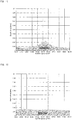
- FIG. 6 is a first graph showing the relation between the cutting force ratio kr and the critical contact angle ⁇ lim .
- the horizontal axis of FIG. 6 represents the cutting force ratio kr.
- the vertical axis of FIG. 6 represents the critical contact angle ⁇ lim (°).
- FIG. 6 shows the relation for the case of up milling and the relation for the case of down milling.
- the transfer function G1 was used for the analysis for determining the relation.
- the difference between the critical contact angle ⁇ lim for the case of up milling and the critical contact angle ⁇ lim for the case of down milling is small.
- the critical contact angle ⁇ lim increases. Regions below the lines of FIG. 6 are ranges in which stable machining is possible. For example, in the case where the cutting force ratio kr is 0.3, the critical contact angle ⁇ lim is about 29°. Therefore, when the contact angle over which the end mill 10 comes into contact with the workpiece M1 is set to 29° or smaller, generation of self-excited vibration can be avoided.
- the difference between the critical contact angle ⁇ lim for the case of up milling and the critical contact angle ⁇ lim for the case of down milling is small.
- the critical contact angle ⁇ lim is slightly greater than that in the case of up milling.
- the end mill machining apparatus 100 can perform machining more stably. Accordingly, down milling is preferred. Namely, it is preferred that the rotation direction of the end mill 10 is opposite the rotation direction of the trochoid locus.
- FIG. 7 is a second graph showing the relation between the cutting force ratio kr and the critical contact angle ⁇ lim .
- the horizontal axis of FIG. 7 represents the cutting force ratio kr.
- the vertical axis of FIG. 7 represents the critical contact angle ⁇ lim (°).
- FIG. 7 shows the relation for the case where the transfer function G1 is used and the relation for the case where the transfer function G2 is used.
- the lines of FIG. 7 show the results of an analysis performed for the case where cutting was performed in a down milling mode. The difference between the critical contact angle ⁇ lim for the case of the transfer function G1 and the critical contact angle ⁇ lim for the case of the transfer function G2 is small.
- the end mill machining apparatus 100 of the present embodiment has the variable helix type thin and long end mill 10, and machines the workpiece M1 by moving the end mill 10 to depict a trochoid locus. Therefore, the variable helix type end mill 10 suppresses (b-1) regenerative self-excited vibration. Also, the machining method which moves the end mill 10 to depict a trochoid locus suppresses (b-2) mode-coupling self-excited vibration. Thus, when a narrow and deep groove is formed, the end mill machining apparatus 100 of the present embodiment can suppress both of (b-1) regenerative self-excited vibration and (b-2) mode-coupling self-excited vibration.
- the end mill machining apparatus 100 can easily form a narrow and deep groove through machining as compared with the conventional end mill machining apparatus. Since self-excited vibrations can be suppressed, the machining accuracy of the end mill machining apparatus 100 of the present embodiment is higher than that of the conventional end mill machining apparatus. Also, the machining speed of the end mill machining apparatus 100 of the present embodiment is higher than that of the conventional end mill machining apparatus. Also, in the end mill machining apparatus 100 of the present embodiment, self-excited vibrations are less likely to be generated. Therefore, the end mill 10 is less likely to be broken.
- the end mill 10 moves to depict a trochoid locus on the workpiece M1.
- the trochoid locus is the locus of a motion produced by superposing a circular motion and a translational motion.
- the end mill 10 does not move in the X-axis direction and the Y-axis direction, and only the workpiece M1 moves in the X-axis direction and the Y-axis direction.
- the end mill 10 may be moved in the X-axis direction and the Y-axis direction.
- the end mill 10 is caused to produce a circular motion
- the workpiece M1 is caused to produce a translational motion.
- the end mill 10 can be moved to depict a trochoid locus on the workpiece M1.
- the end mill machining apparatus 100 of the present embodiment may use a variable pitch, uniform lead end mill in place of the variable lead end mill 10. In this case as well, (b-1) regenerative self-excited vibration can be suppressed.
- the control section 150 includes a chatter vibration frequency detection section and a computation section.
- the chatter vibration frequency detection section has a function of detecting the frequency of chatter vibration of the end mill 10.
- the computation section computes a spindle rotational speed and a trochoid locus which can properly suppress self-excited vibrations, on the basis of the above-described chatter vibration frequency, the above-described information of the tooth portion, and the above-described information of the material of the workpiece M1.
- the X-axis, Y-axis, and Z-axis coordinates of the end mill 10; namely, the relative position of the end mill 10 with respect to the workpiece M1 are adjusted as in the end mill machining apparatus 100.
- the present embodiment merely shows one example thereof, and the present invention is not limited thereto.
- the end mill machining apparatus 100 of the present embodiment has the variable helix type thin and long end mill 10, and machines the workpiece M1 by moving the end mill 10 to depict a trochoid locus. Therefore, when a narrow and deep groove is formed through machining, the end mill machining apparatus 100 of the present embodiment can suppress both of (b-1) regenerative self-excited vibration and (b-2) mode-coupling self-excited vibration. As a result, the end mill machining apparatus 100 can easily form a narrow and deep groove through machining as compared with the conventional end mill machining apparatus.
- the machining accuracy of the end mill machining apparatus 100 of the present embodiment is higher than that of the conventional end mill machining apparatus. Also, the machining speed of the end mill machining apparatus 100 of the present embodiment is higher than that of the conventional end mill machining apparatus. Also, in the end mill machining apparatus 100 of the present embodiment, self-excited vibrations are less likely to be generated. Therefore, the end mill 10 is less likely to be broken.
- a second embodiment will be described.
- a machining system which includes the end mill machining apparatus of the first embodiment will be described.
- FIG. 8 shows the overall configuration of the present embodiment.
- the machining system 1 includes a CAD/CAM apparatus A1, an NC program preparation apparatus A2, and the end mill machining apparatus 100.
- the CAD/CAM apparatus A1 includes a CAD function section which performs part design, mold design, etc., and a CAM function section which designs a production process from 3D data produced as a result of the part design, mold design, etc. and determines NC data, including a tool locus, a depth of cut, etc.
- the NC program preparation apparatus A2 produces an NC program from the NC data determined by the CAD/CAM apparatus A1.
- the CAD/CAM apparatus A1 determines a trochoid locus in consideration of the shape of the end mill 10. Then, on the basis of the diameter D and the protrusion length L of the end mill 10, etc., the CAD/CAM apparatus A1 determines the rotational speed of the end mill 10 and the depth of cut in the axial direction which fall within a stable region determined from the results of an analysis which will be described later. Namely, the CAD/CAM apparatus A1 holds data of a stable region for machining which is determined, from the results of the below-described analysis, for each of combinations of the diameters D and the protrusion lengths L of various types of end mills 10.
- the CAD/CAM apparatus A1 aids process design and work design by using the information representing the shape of the end mill 10 and the information representing the material of the workpiece M1. Specifically, on the basis of data of the workpiece M1 and data of the stable region for the combination of the diameter D and the protrusion length L of an end mill 10 to be used, the CAD/CAM apparatus A1 performs design assist so as to obtain optimal machining conditions.
- design assist used herein refers to "assisting the process design and the work design.”
- an NC program operates the end mill machining apparatus 100 on the basis of the information representing the shape of the end mill 10 and the information representing the material of the workpiece M1. Specifically, on the basis of data of the workpiece M1 and data of the stable region for the combination of the diameter D and the protrusion length L of an end mill 10 to be used, the NC program may determine the rotational speed of the end mill 10 and the depth of cut in the axial direction within the stable region.
- the end mill machining apparatus 100 having been described above can produce not only a groove shape but also other three-dimensional shapes through machining.
- a third embodiment will be described.
- a locus which differs from the trochoid locus of the first embodiment will be described.
- Loci which will be described below may be employed as long as the contact angle between the end mill 10 and the workpiece M1 is equal to or smaller than the critical contact angle ⁇ lim .
- FIG. 9 shows the case where the locus of the end mill 10 is the locus of a motion produced by superposing an elliptical motion and a translational motion.
- the contact angle between the end mill 10 and the workpiece M1 can be made equal to or smaller than the critical contact angle ⁇ lim . In this case as well, mode-coupling self-excited vibration can be suppressed.
- FIG. 10 shows the case where the locus of the end mill 10 is the locus of a motion produced by superposing a triangular rotational motion and a translational motion.
- the contact angle between the end mill 10 and the workpiece M1 can be made equal to or smaller than the critical contact angle ⁇ lim . In this case as well, mode-coupling self-excited vibration can be suppressed.
- the contact angle between the end mill 10 and the workpiece M1 can be made equal to or smaller than the critical contact angle ⁇ lim .
- an arbitrary curvilinear motion may be employed instead of the translational motion.
- the control section 150 controls the end mill 10 to move relative to the workpiece M1 so as to depict the locus of a motion produced by superposing a closed-curvilinear motion on a rectilinear motion or a curvilinear motion.
- the machining methods of the first embodiment and the third embodiment are used.
- this analysis does not involve the conditions on the locus of the end mill.
- the case (C4) corresponds to the case where the end mill 10 is controlled to depict the locus of a motion produced by superposing a rectilinear motion or a curvilinear motion on an arbitrary closed-curvilinear motion.
- Table 2 shows the specifications of the end mill used in the analysis. [Table 2] Type Diameter Number of teeth Helix angle ⁇ 1 Helix angle ⁇ 2 Uniform pitch, uniform lead 6 mm 2 30° 30° Variable lead 6 mm 2 27.05° 32.79°
- FIG. 11 is a graph showing the results of an analysis performed for the case where slotting was performed through use of a uniform pitch, uniform lead end mill.
- the horizontal axis of FIG. 11 represents the rotational speed (rpm) of the end mill.
- the vertical axis of FIG. 11 represents the depth of cut (mm) in the axial direction.
- stable machining is possible when the axial depth of cut of the end mill is about 0.01 mm. Therefore, when a groove having a depth of several centimeters to several tens of centimeters is formed through machining, a very long machining time is needed.
- FIG. 12 is a graph showing the results of an analysis performed for the case where slotting was performed through use of a variable lead end mill.
- the horizontal axis of FIG. 12 represents the rotational speed (rpm) of the end mill.
- the vertical axis of FIG. 12 represents the depth of cut (mm) in the axial direction.
- stable machining is possible when the axial depth of cut of the end mill is about 0.01 mm. Therefore, when a groove having a depth of several centimeters to several tens of centimeters is formed through machining, a very long machining time is needed.
- FIG. 13 is a graph showing the results of an analysis performed for the case where machining was performed through use of a uniform pitch, uniform lead end mill.
- the horizontal axis of FIG. 13 represents the rotational speed (rpm) of the end mill.
- the vertical axis of FIG. 13 represents the depth of cut (mm) in the axial direction.
- stable machining is possible when the axial depth of cut of the end mill is about 0.2 mm. Therefore, when a groove having a depth of several centimeters to several tens of centimeters is formed through machining, a rather long machining time is needed.
- FIG. 14 is a graph showing the results of an analysis performed for the case where machining was performed through use of a variable lead end mill.
- the horizontal axis of FIG. 14 represents the rotational speed (rpm) of the end mill.
- the vertical axis of FIG. 14 represents the depth of cut (mm) in the axial direction.
- stable machining is possible when the axial depth of cut of the end mill is about 1 mm.
- the axial depth of cut of the end mill is 7 mm to 9 mm, machining can be performed stably. Therefore, when a groove having a depth of several centimeters to several tens of centimeters is formed through machining, only a short machining time is needed.
- a volume removal ratio VR1 at a rotational speed for enabling the most preferred machining was 37 (a.u.).
- a volume removal ratio VR2 at a rotational speed for enabling the most preferred machining was 21 (a.u.).
- a volume removal ratio VR3 at a rotational speed for enabling the most preferred machining was 41 (a.u.).
- a volume removal ratio VR4 at a rotational speed for enabling the most preferred machining was 497 (a.u.). Accordingly, the machining methods of the first embodiment and the third embodiment ( FIG. 14 ) each have an efficiency at least 12 times the efficiencies of the conventional machining methods ( FIGS. 11, 12 , and 13 ).
- the end mill machining apparatuses 100 of the first embodiment and the third embodiment suppress (b-1) regenerative self-excited vibration and (b-2) mode-coupling self-excited vibration.
- the end mill machining apparatuses 100 each have an improved machining stability. This is because the above-described two types of self-excited vibrations are likely to increase exponentially and are very sensitive to machining stability.
- the present disclosure includes an end mill machining apparatus, a CAM apparatus, an NC program, and a machining method which are itemized below.
- An end mill machining apparatus which includes an end mill and a control section for controlling the end mill, wherein a ratio of a protrusion length of the end mill to a diameter of the end mill falls within a range of 5 to 50, the end mill is a variable pitch, uniform helix type or a variable helix type, and the control section controls a contact angle between the end mill and the workpiece during machining to a critical contact angle ⁇ lim or smaller.
- This end mill machining apparatus can suppress generation of regenerative self-excited vibration and mode-coupling self-excited vibration. Therefore, breakage of the end mill hardly occurs. Also, machining accuracy hardly deteriorates due to intensification of vibration. Therefore, this end mill machining apparatus is suitable for formation of a narrow and deep groove through machining.
- control section controls the end mill to move relative to a workpiece so as to depict a locus of a motion produced by superposing a closed-curvilinear motion and a rectilinear motion or a curvilinear motion.
- control section controls the end mill to move relative to a workpiece so as to depict a trochoid locus.
- an axial depth of cut of the end mill is equal to or greater than one-sixth of a diameter of the end mill.
- a rotation direction of the end mill is opposite a rotation direction of the trochoid locus.
- NC program for operating the end mill machining apparatus described in any one of Items 1 to 5 the NC program operating the end mill machining apparatus on the basis of tooth information of the end mill and material information of the workpiece.
- a machining method for machining a workpiece by using an end mill comprising: using, as the end mill, an end mill of a variable pitch, uniform helix type or a variable helix type which is configured such that a ratio of a protrusion length of the end mill to a diameter of the end mill falls within a range of 5 to 50; and machining the workpiece in a state in which a contact angle between the end mill and the workpiece during the machining is a critical contact angle ⁇ lim or smaller.
- the workpiece is machined by moving the end mill relative to the workpiece to depict a trochoid locus.
Landscapes
- Engineering & Computer Science (AREA)
- Mechanical Engineering (AREA)
- Physics & Mathematics (AREA)
- Human Computer Interaction (AREA)
- Manufacturing & Machinery (AREA)
- General Physics & Mathematics (AREA)
- Automation & Control Theory (AREA)
- Geometry (AREA)
- Numerical Control (AREA)
- Milling Processes (AREA)
- Automatic Control Of Machine Tools (AREA)
Abstract
Description
- The technique of the present specification relates to an end mill machining apparatus, a CAM apparatus, an NC program, and a machining method. More specifically, the technique relates to an end mill machining apparatus, a CAM apparatus, NC program, and a machining method which suppress vibrations during machining.
- Cutting is frequently used in processes of manufacturing industrial products. For example, cutting is used for direct machining of products and machining of dies. When such cutting is performed, chatter vibrations may be generated on a tool. Chatter vibrations cause a deterioration in the shape of a finished surface or breakage of the tool.
- Chatter vibrations include two types of vibrations; i.e., forced vibration and self-excited vibration. Forced vibration is a vibration which is generated when some forced causal vibration is amplified by the vibration characteristic of a machine. For example, intermittent cutting force generated during end milling or the like causes forced vibration. However, in some cases, the term "chatter vibration" does not encompass forced vibration. Self-excited vibration is a vibration which is generated when a vibration generated in a cutting process grows (i.e., is amplified) because of a presence of a closed loop that feeds back the generated vibration.
- Major types of self-excited vibration include a regenerative type self-excited vibration and a mode-coupling type self-excited vibration. Regenerative self-excited vibration is generated, for example, when a vibration generated during cutting in a previous rotation or cutting by a preceding tooth has remained as an undulation of the machined surface, the uncut chip thickness fluctuates in time due to the remaining shape and a vibration at the present point. Mode-coupling self-excited vibration is generated, for example, when vibration modes in two directions have resonance frequencies close to each other and the vibrations in the two directions are coupled. Such chatter vibrations are collectively shown in the following Table 1.
[Table 1] (a) forced vibration (b) self-excited vibration (b-1) regenerative self-excited vibration (b-2) mode-coupling self-excited vibration - Therefore, techniques for suppressing chatter vibrations have been developed. For example,
Patent Document 1 discloses an unequally divided end mill which has an odd number of cutting teeth and in which dividing angles different from one another are provided for the cutting teeth. - Patent Document 1: Japanese Patent Application Laid-Open (kokai) No.
2000-714 - In this end mill, the phase of the "regenerative effect" remaining on a machined surface and changing the uncut chip thickness at the present point in time is not fixed. Therefore, regenerative self-excited vibration can be suppressed. However, the end mill disclosed in
Patent Document 1 encounters difficulty in suppressing mode-coupling self-excited vibration. - In recent years, in manufacture of dies, there has been an increasing need to form a groove that has a large depth as compared with the width of the groove. Formation of such a deep groove requires an end mill which is large in the ratio of its protrusion length to its outer diameter; i.e., a thin, long end mill. When such a thin, long end mill is used, self-excited vibration becomes more likely to be generated as compared with the case of a thick end mill.
- The technique disclosed in the present specification has been accomplished so as to solve the above-described problem of the conventional technique. Its objective is to provide an end mill machining apparatus, a CAM apparatus, an NC program, and a machining method which suppress regenerative self-excited vibration and mode-coupling self-excited vibration.
- An end mill machining apparatus according to one mode of the present disclosure comprises an end mill, and a control section for controlling the end mill. The ratio of a protrusion length of the end mill to a diameter of the end mill falls within a range of 5 to 50. The end mill is a variable pitch, uniform helix type or a variable helix type. The control section controls a contact angle between the end mill and the workpiece during machining to a critical contact angle θlim or smaller.
- In the present specification, there are provided an end mill machining apparatus, a CAM apparatus, an NC program, and a machining method which suppress regenerative self-excited vibration and mode-coupling self-excited vibration.
-
- [
FIG. 1 ] View schematically showing the structure of an end mill machining apparatus according to a first embodiment. - [
FIG. 2 ] Sectional view of the structure of an end mill and its vicinity of the end mill machining apparatus according to the first embodiment. - [
FIG. 3 ] Block diagram showing the control system of the end mill machining apparatus according to the first embodiment. - [
FIG. 4 ] First illustration used for describing a trochoid locus of the end mill in the first embodiment. - [
FIG. 5 ] Second illustration used for describing the trochoid locus of the end mill in the first embodiment. - [
FIG. 6 ] First graph showing the relation between cutting force ratio kr and critical contact angle θlim. - [
FIG. 7 ] Second graph showing the relation between cutting force ratio kr and critical contact angle θlim. - [
FIG. 8 ] Conceptual diagram used for describing an end mill machining system according to a second embodiment. - [
FIG. 9 ] Illustration showing a locus of a motion produced by superposing an elliptical motion and a translational motion. - [
FIG. 10 ] Illustration showing a locus of a motion produced by superposing a triangular rotational motion and a translational motion. - [
FIG. 11 ] Graph showing the results of an analysis performed for the case where slotting was performed through use of a uniform pitch, uniform lead end mill. - [
FIG. 12 ] Graph showing the results of an analysis performed for the case where slotting was performed through use of a variable lead end mill. - [
FIG. 13 ] Graph showing the results of an analysis performed for the case where trochoid machining was performed through use of a uniform pitch, uniform lead end mill. - [
FIG. 14 ] Graph showing the results of an analysis performed for the case where trochoid machining was performed through use of a variable lead end mill. - Specific embodiments will now be described with reference to the drawings, with an end mill machining apparatus, a CAM apparatus, an NC program, and a machining method being used as examples.
-
FIG. 1 is a view showing an endmill machining apparatus 100 of the present embodiment. The endmill machining apparatus 100 includes anend mill 10, amachining unit 130, abody 101, anX-axis motor 111, a Y-axis motor 112, a Z-axis motor 113, anX-axis sensor 121, a Y-axis sensor 122, a Z-axis sensor 123, an X-axis feed table 141, a Y-axis feed table 142, and acontrol section 150. - The
end mill 10 is a tool for machining a workpiece which is to be machined actually. Theend mill 10 has atooth portion 11 for machining the workpiece, and anon-tooth portion 12 which is formed integrally with thetooth portion 11 and which has no cutting teeth. Thetooth portion 11 is located on the distal end side with respect to thenon-tooth portion 12. - The
machining unit 130 supports a spindle which holds theend mill 10. Themachining unit 130 can be moved in a Z-axis direction by the Z-axis motor 113. - The X-axis feed table 141 is a table on which a workpiece M1 is disposed. The X-axis feed table 141 can be moved in an X-axis direction by the
X-axis motor 111. The Y-axis feed table 142 can be moved in a Y-axis direction by the Y-axis motor 112. Therefore, the X-axis feed table 141 can be moved in the X-axis direction and the Y-axis direction. - The
X-axis motor 111 is used to move the X-axis feed table 141 in the X-axis direction. The Y-axis motor 112 is used to move the Y-axis feed table 142 in the Y-axis direction. The Z-axis motor 113 is used to move themachining unit 130 in the Z-axis direction. These motors enable adjustment of the position of theend mill 10 relative to the workpiece M1. -
FIG. 2 is a sectional view schematically showing the internal structure of themachining unit 130. Themachining unit 130 includes atool holder 131, arotation spindle 132, and aspindle bearing 133, as well as theend mill 10. - The
tool holder 131 is a tool holding portion which grasps theend mill 10 and couples theend mill 10 with therotation spindle 132. Thetool holder 131 has arecess 131a. Theend mill 10 is held in a state in which it is received by therecess 131a. A holding mechanism of thetool holder 131 for holding theend mill 10 is the same as that used in the conventional technique. Thetool holder 131 is coupled with therotation spindle 132 and is rotationally driven by therotation spindle 132. Namely, thetool holder 131 rotates together with theend mill 10. - The
spindle bearing 133 is one of bearings for supporting therotation spindle 132. Therefore, the spindle bearing 133 supports all rotation members (from therotation spindle 132 to the end mill 10) which rotate together. - The
control section 150 controls respective portions of the endmill machining apparatus 100. In particular, thecontrol section 150 controls theend mill 10 to depict a trochoid locus on the workpiece M1. - The
end mill 10 is very thin and long as compared with conventional end mills. The ratio of the protrusion length L of theend mill 10 to the diameter D of theend mill 10; i.e., the L/D ratio, is 5 to 50. The machining method of the present embodiment is suitable for the case where the ratio of the protrusion length L of theend mill 10 to the diameter D of theend mill 10; i.e., the L/D ratio, is 10 to 50. - The
end mill 10 is of a variable helix type. Thetooth portion 11 of theend mill 10 has, for example, two cutting teeth (blades). The number of the cutting teeth of thetooth portion 11 may be three or more. -
FIG. 3 shows the control system of the present embodiment. As shown inFIG. 3 , thecontrol section 150 includes an NCprogram storage section 161, aprogram analysis section 162, amotor control section 170, andother control sections 180. - The NC
program storage section 161 stores an NC program. Theprogram analysis section 162 analyzes the NC program stored in the NCprogram storage section 161 and executes the program. Themotor control section 170 controls the motors. - The
motor control section 170 includes anX-axis control section 171, a Y-axis control section 172, a Z-axis control section 173, and aspindle control section 174. TheX-axis control section 171 controls the position of the workpiece M1 in the X-axis direction. The term "position" used herein refers to the relative position of theend mill 10 with respect to the workpiece M1. The Y-axis control section 172 controls the position of the workpiece M1 in the Y-axis direction. The Z-axis control section 173 controls the position of the workpiece M1 in the Z-axis direction. Thespindle control section 174 controls rotation of the spindle supporting theend mill 10. - The
X-axis sensor 121 measures the position of the workpiece M1 in the X-axis direction. The Y-axis sensor 122 measures the position of the workpiece M1 in the Y-axis direction. The Z-axis sensor 123 measures the position of the workpiece M1 in the Z-axis direction. TheX-axis motor 111 changes the position of the workpiece M1 in the X-axis direction. The Y-axis motor 112 changes the position of the workpiece M1 in the Y-axis direction. The Z-axis motor 113 changes the position of the workpiece M1 in the Z-axis direction. The Z-axis motor 113 may change the position in the Z-axis direction of themachining unit 130 having theend mill 10. - The
spindle sensor 124 detects rotation of the spindle. Thespindle motor 114 rotates the spindle. Aninput receiving section 191 receives instructions entered by an operator. For example, theinput receiving section 191 can receive the input of information representing the shape of theend mill 10 and information representing the material of the workpiece M1.Other portions 190 refer to structural portions of the endmill machining apparatus 100 other than the above-described portions. - As described above, the
control section 150 controls the various portions of the endmill machining apparatus 100. As will be described later, thecontrol section 150 controls theend mill 10 to depict a trochoid locus on the workpiece M1. In actuality, theX-axis control section 171 and the Y-axis control section 172 control theX-axis motor 111 and the Y-axis motor 112, respectively, such that theend mill 10 depicts a trochoid locus on the workpiece M1. - Here, a machining method of the end
mill machining apparatus 100 of the present embodiment will be described. In this machining method, thecontrol section 150 controls machining on the basis of the NC program. In the present embodiment, thecontrol section 150 of the endmill machining apparatus 100 controls theend mill 10 to depict a trochoid locus on the workpiece M1. -
FIG. 4 is an illustration showing a trochoid locus depicted by theend mill 10. Since trochoid machining is performed, a contact angle, which is an angular range within which theend mill 10 is in contact with the workpiece M1 during machining, can be rendered smaller. Therefore, the trochoid machining can suppress (b-2) mode-coupling self-excited vibration. -
FIG. 5 is an illustration showing the contact angle of theend mill 10 with respect to the workpiece M1 in the case where theend mill 10 is moved to depict a trochoid locus. The term "contact angle" used herein refers to an angular range within which thetooth portion 11 of theend mill 10 is in contact with the workpiece M1. A critical contact angle θlim refers to the maximum contact angle at which no mode-coupling self-excited vibration is generated. This critical contact angle θlim will be described later. - As a result of use of the variable
lead end mill 10, (b-1) regenerative self-excited vibration can be suppressed. - As described above, both (b-1) regenerative self-excited vibration and (b-2) mode-coupling self-excited vibration can be suppressed when (1) the variable
lead end mill 10 is used, (2) the workpiece M1 is machined by moving theend mill 10 to depict a trochoid locus, and (3) the workpiece M1 is machined with a contact angle equal to or smaller than the critical contact angle θlim. Therefore, even when a large axial depth of cut P1 (seeFIG. 2 ) is employed, stable machining can be performed. - Accordingly, the
control section 150 renders the angle of contact between theend mill 10 and the workpiece M1 during machining equal to or smaller than the critical contact angle θlim. As will be described later, for stabilization of machining, the axial depth of cut P1 of theend mill 10 is set to fall with the range of 7 mm to 9 mm. Therefore, as will be described later, productivity becomes 10 times or more. - The axial depth of cut P1 is considered to depend on the diameter D of the
end mill 10. The greater the diameter D of theend mill 10, the greater the value to which the axial depth of cut P1 can be set. Therefore, the axial depth of cut P1 can be set to a value which is equal to or greater than 1/6 of the diameter D of theend mill 10. - Here, the critical contact angle θlim will be described. The contact angle is an angle range over which the
tooth portion 11 of theend mill 10 is in contact with the workpiece M1. The critical contact angle θlim is the maximum contact angle at which no mode-coupling self-excited vibration is generated. Namely, no self-excited vibration is generated in the case where trochoid machining is performed in a state in which theend mill 10 is in contact with the workpiece M1 over a contact angle equal to or smaller than the critical contact angle θlim. Self-excited vibration may be generated in the case where trochoid machining is performed in a state in which theend mill 10 is in contact with the workpiece M1 over a contact angle greater than the critical contact angle θlim. - The workpiece M1 and the shape of the cutting teeth of the
end mill 10 determine the critical contact angle θlim. Therefore, when information representing the shape of theend mill 10 and information representing the material of the workpiece M1 are input to the endmill machining apparatus 100, the endmill machining apparatus 100 can perform machining while suppressing mode-coupling self-excited vibration. - In general, the following critical equation determines the stability against regenerative self-excited vibration and mode-coupling self-excited vibration.
[Equation 1]
- I: two-dimensional unit matrix
- a: axial depth of cut
- Kt: specific cutting force
- ωc: chatter frequency
- T: inter-tooth delay time
- A0: DC component of a cutting force coefficient matrix
- G(iωc): transfer function at the chatter frequency
- The DC component A0 of the cutting force coefficient matrix is given by the following equation.
[Equation 2]


- N: number of cutting teeth
- kr: cutting force ratio
- θst: cutting start angle of each tooth
- θed: cutting end angle of each tooth
- The cutting force ratio kr is the ratio of thrust force to principal force. The cutting force ratio kr is represented by an equation of kr = K2/K1 where K1 is the specific cutting force in the principal force direction, and K2 is the specific cutting force in the thrust force direction. In the case of up milling, θst = 0 and θed = θlim. In the case of down milling, θst = π - θlim and θed = π.
- Under the assumption that the variable lead end mill exhibits its complete effect, the regenerative term exp(-iωcT) of Equation (1) becomes zero. Namely, Equation (1) is represented by the following equation.
[Equation 3]
- The axial depth of cut a and the chatter frequency ωc which make both the real and imaginal parts of Equation (3) zero are a critical axial depth of cut alim and a critical frequency ωclim at which self-excited vibration may be generated.
- The transfer function G is represented by using modal parameters. Here, the nondiagonal terms Gxy and Gyx are assumed to be considerably smaller than the diagonal terms Gxx and Gyy, and Gxy and Gyx are set to 0. Thus, the transfer function G is represented by the following equation.
[Equation 4]
- Notably, even when Gxy and Gyx are set to zero, the nondiagonal components of the DC component A0 of the cutting force coefficient matrix are not zero. Therefore, even under the above-described assumption, mode-coupling self-excited vibration may be generated. Namely, the analysis performed here is an analysis under the conditions in which mode-coupling self-excited vibration may be generated. Also, since the
end mill 10 is approximately axial symmetry, the assumption that Gxy = Gyx = 0 is considered to be appropriate. - Under the conditions of the above-described Equations (3) and (4), the relation between cutting force ratio kr and critical contact angle θlim was analyzed. For the analysis, 2406 (Mpa) was used as the specific cutting force Kt. Also, the following transfer functions G1 and G2 were used.
G1


- Notably, the contact angle θ at which a solution satisfying Equation (3) did not appear even when the axial depth of cut a was increased infinitely was employed as the critical contact angle θlim.
-
FIG. 6 is a first graph showing the relation between the cutting force ratio kr and the critical contact angle θlim. The horizontal axis ofFIG. 6 represents the cutting force ratio kr. The vertical axis ofFIG. 6 represents the critical contact angle θlim (°).FIG. 6 shows the relation for the case of up milling and the relation for the case of down milling. The transfer function G1 was used for the analysis for determining the relation. The difference between the critical contact angle θlim for the case of up milling and the critical contact angle θlim for the case of down milling is small. - As shown in
FIG. 6 , as the cutting force ratio kr increases, the critical contact angle θlim increases. Regions below the lines ofFIG. 6 are ranges in which stable machining is possible. For example, in the case where the cutting force ratio kr is 0.3, the critical contact angle θlim is about 29°. Therefore, when the contact angle over which theend mill 10 comes into contact with the workpiece M1 is set to 29° or smaller, generation of self-excited vibration can be avoided. - As shown in
FIG. 6 , the difference between the critical contact angle θlim for the case of up milling and the critical contact angle θlim for the case of down milling is small. However, in the case of down milling, the critical contact angle θlim is slightly greater than that in the case of up milling. Namely, through employment of down milling, the endmill machining apparatus 100 can perform machining more stably. Accordingly, down milling is preferred. Namely, it is preferred that the rotation direction of theend mill 10 is opposite the rotation direction of the trochoid locus. -
FIG. 7 is a second graph showing the relation between the cutting force ratio kr and the critical contact angle θlim. The horizontal axis ofFIG. 7 represents the cutting force ratio kr. The vertical axis ofFIG. 7 represents the critical contact angle θlim (°).FIG. 7 shows the relation for the case where the transfer function G1 is used and the relation for the case where the transfer function G2 is used. The lines ofFIG. 7 show the results of an analysis performed for the case where cutting was performed in a down milling mode. The difference between the critical contact angle θlim for the case of the transfer function G1 and the critical contact angle θlim for the case of the transfer function G2 is small. - As shown in
FIG. 7 , as the cutting force ratio kr increases, the critical contact angle θlim increases. Regions below the lines ofFIG. 7 are ranges in which stable machining is possible. - The end
mill machining apparatus 100 of the present embodiment has the variable helix type thin andlong end mill 10, and machines the workpiece M1 by moving theend mill 10 to depict a trochoid locus. Therefore, the variable helixtype end mill 10 suppresses (b-1) regenerative self-excited vibration. Also, the machining method which moves theend mill 10 to depict a trochoid locus suppresses (b-2) mode-coupling self-excited vibration. Thus, when a narrow and deep groove is formed, the endmill machining apparatus 100 of the present embodiment can suppress both of (b-1) regenerative self-excited vibration and (b-2) mode-coupling self-excited vibration. - As described above, the end
mill machining apparatus 100 can easily form a narrow and deep groove through machining as compared with the conventional end mill machining apparatus. Since self-excited vibrations can be suppressed, the machining accuracy of the endmill machining apparatus 100 of the present embodiment is higher than that of the conventional end mill machining apparatus. Also, the machining speed of the endmill machining apparatus 100 of the present embodiment is higher than that of the conventional end mill machining apparatus. Also, in the endmill machining apparatus 100 of the present embodiment, self-excited vibrations are less likely to be generated. Therefore, theend mill 10 is less likely to be broken. - In the end
mill machining apparatus 100 of the present embodiment, theend mill 10 moves to depict a trochoid locus on the workpiece M1. The trochoid locus is the locus of a motion produced by superposing a circular motion and a translational motion. In the present embodiment, theend mill 10 does not move in the X-axis direction and the Y-axis direction, and only the workpiece M1 moves in the X-axis direction and the Y-axis direction. However, theend mill 10 may be moved in the X-axis direction and the Y-axis direction. For example, whereas theend mill 10 is caused to produce a circular motion, the workpiece M1 is caused to produce a translational motion. In this case as well, theend mill 10 can be moved to depict a trochoid locus on the workpiece M1. - The end
mill machining apparatus 100 of the present embodiment may use a variable pitch, uniform lead end mill in place of the variablelead end mill 10. In this case as well, (b-1) regenerative self-excited vibration can be suppressed. - Preferably, the
control section 150 includes a chatter vibration frequency detection section and a computation section. The chatter vibration frequency detection section has a function of detecting the frequency of chatter vibration of theend mill 10. The computation section computes a spindle rotational speed and a trochoid locus which can properly suppress self-excited vibrations, on the basis of the above-described chatter vibration frequency, the above-described information of the tooth portion, and the above-described information of the material of the workpiece M1. - In the present embodiment, the X-axis, Y-axis, and Z-axis coordinates of the
end mill 10; namely, the relative position of theend mill 10 with respect to the workpiece M1 are adjusted as in the endmill machining apparatus 100. However, needless to say, there exist other methods for adjusting the relative position of theend mill 10 with respect to the workpiece M1 by using actuators. The present embodiment merely shows one example thereof, and the present invention is not limited thereto. - Needless to say, the above-described modifications may be combined freely.
- The end
mill machining apparatus 100 of the present embodiment has the variable helix type thin andlong end mill 10, and machines the workpiece M1 by moving theend mill 10 to depict a trochoid locus. Therefore, when a narrow and deep groove is formed through machining, the endmill machining apparatus 100 of the present embodiment can suppress both of (b-1) regenerative self-excited vibration and (b-2) mode-coupling self-excited vibration. As a result, the endmill machining apparatus 100 can easily form a narrow and deep groove through machining as compared with the conventional end mill machining apparatus. - Since self-excited vibrations can be suppressed, the machining accuracy of the end
mill machining apparatus 100 of the present embodiment is higher than that of the conventional end mill machining apparatus. Also, the machining speed of the endmill machining apparatus 100 of the present embodiment is higher than that of the conventional end mill machining apparatus. Also, in the endmill machining apparatus 100 of the present embodiment, self-excited vibrations are less likely to be generated. Therefore, theend mill 10 is less likely to be broken. - A second embodiment will be described. In the present embodiment, a machining system which includes the end mill machining apparatus of the first embodiment will be described.
-
FIG. 8 shows the overall configuration of the present embodiment. As shown inFIG. 8 , themachining system 1 includes a CAD/CAM apparatus A1, an NC program preparation apparatus A2, and the endmill machining apparatus 100. - The CAD/CAM apparatus A1 includes a CAD function section which performs part design, mold design, etc., and a CAM function section which designs a production process from 3D data produced as a result of the part design, mold design, etc. and determines NC data, including a tool locus, a depth of cut, etc. The NC program preparation apparatus A2 produces an NC program from the NC data determined by the CAD/CAM apparatus A1.
- The CAD/CAM apparatus A1 determines a trochoid locus in consideration of the shape of the
end mill 10. Then, on the basis of the diameter D and the protrusion length L of theend mill 10, etc., the CAD/CAM apparatus A1 determines the rotational speed of theend mill 10 and the depth of cut in the axial direction which fall within a stable region determined from the results of an analysis which will be described later. Namely, the CAD/CAM apparatus A1 holds data of a stable region for machining which is determined, from the results of the below-described analysis, for each of combinations of the diameters D and the protrusion lengths L of various types ofend mills 10. - Therefore, the CAD/CAM apparatus A1 aids process design and work design by using the information representing the shape of the
end mill 10 and the information representing the material of the workpiece M1. Specifically, on the basis of data of the workpiece M1 and data of the stable region for the combination of the diameter D and the protrusion length L of anend mill 10 to be used, the CAD/CAM apparatus A1 performs design assist so as to obtain optimal machining conditions. The term "design assist" used herein refers to "assisting the process design and the work design." - Alternatively, an NC program operates the end
mill machining apparatus 100 on the basis of the information representing the shape of theend mill 10 and the information representing the material of the workpiece M1. Specifically, on the basis of data of the workpiece M1 and data of the stable region for the combination of the diameter D and the protrusion length L of anend mill 10 to be used, the NC program may determine the rotational speed of theend mill 10 and the depth of cut in the axial direction within the stable region. - Needless to say, the end
mill machining apparatus 100 having been described above can produce not only a groove shape but also other three-dimensional shapes through machining. - A third embodiment will be described. In the present embodiment, a locus which differs from the trochoid locus of the first embodiment will be described. Loci which will be described below may be employed as long as the contact angle between the
end mill 10 and the workpiece M1 is equal to or smaller than the critical contact angle θlim. -
FIG. 9 shows the case where the locus of theend mill 10 is the locus of a motion produced by superposing an elliptical motion and a translational motion. As shown inFIG. 9 , even when the locus of a motion produced by superposing an elliptical motion and a translational motion is used as the locus of theend mill 10, the contact angle between theend mill 10 and the workpiece M1 can be made equal to or smaller than the critical contact angle θlim. In this case as well, mode-coupling self-excited vibration can be suppressed. -
FIG. 10 shows the case where the locus of theend mill 10 is the locus of a motion produced by superposing a triangular rotational motion and a translational motion. As shown inFIG. 10 , even when the locus of a motion produced by superposing a quasi-triangular rotational motion and a translational motion is used as the locus of theend mill 10, the contact angle between theend mill 10 and the workpiece M1 can be made equal to or smaller than the critical contact angle θlim. In this case as well, mode-coupling self-excited vibration can be suppressed. - Even in the case of use of the locus of a motion produced by superposing an arbitrary closed-curvilinear motion and a translational motion, the contact angle between the
end mill 10 and the workpiece M1 can be made equal to or smaller than the critical contact angle θlim. Also, instead of the translational motion, an arbitrary curvilinear motion may be employed. In such a case, thecontrol section 150 controls theend mill 10 to move relative to the workpiece M1 so as to depict the locus of a motion produced by superposing a closed-curvilinear motion on a rectilinear motion or a curvilinear motion. - An analysis which was carried out on the stability of machining on the above-described results will be described. In the present analysis, simulation was performed for the following four cases:
- (C1) the case where slotting was performed with a uniform pitch, uniform lead end mill;
- (C2) the case where slotting was performed with a variable lead end mill;
- (C3) the case where machining was performed with a uniform pitch, uniform lead end mill; and
- (C4) the case where machining was performed with a variable lead end mill.
- In the case (C4), the machining methods of the first embodiment and the third embodiment are used. However, this analysis does not involve the conditions on the locus of the end mill. Namely, the case (C4) corresponds to the case where the
end mill 10 is controlled to depict the locus of a motion produced by superposing a rectilinear motion or a curvilinear motion on an arbitrary closed-curvilinear motion. Table 2 shows the specifications of the end mill used in the analysis.[Table 2] Type Diameter Number of teeth Helix angle β1 Helix angle β2 Uniform pitch, uniform lead 6 mm 2 30° 30° Variable lead 6 mm 2 27.05° 32.79° -
FIG. 11 is a graph showing the results of an analysis performed for the case where slotting was performed through use of a uniform pitch, uniform lead end mill. The horizontal axis ofFIG. 11 represents the rotational speed (rpm) of the end mill. The vertical axis ofFIG. 11 represents the depth of cut (mm) in the axial direction. As shown inFIG. 11 , stable machining is possible when the axial depth of cut of the end mill is about 0.01 mm. Therefore, when a groove having a depth of several centimeters to several tens of centimeters is formed through machining, a very long machining time is needed. -
FIG. 12 is a graph showing the results of an analysis performed for the case where slotting was performed through use of a variable lead end mill. The horizontal axis ofFIG. 12 represents the rotational speed (rpm) of the end mill. The vertical axis ofFIG. 12 represents the depth of cut (mm) in the axial direction. As shown inFIG. 12 , stable machining is possible when the axial depth of cut of the end mill is about 0.01 mm. Therefore, when a groove having a depth of several centimeters to several tens of centimeters is formed through machining, a very long machining time is needed. -
FIG. 13 is a graph showing the results of an analysis performed for the case where machining was performed through use of a uniform pitch, uniform lead end mill. The horizontal axis ofFIG. 13 represents the rotational speed (rpm) of the end mill. The vertical axis ofFIG. 13 represents the depth of cut (mm) in the axial direction. As shown inFIG. 13 , stable machining is possible when the axial depth of cut of the end mill is about 0.2 mm. Therefore, when a groove having a depth of several centimeters to several tens of centimeters is formed through machining, a rather long machining time is needed. -
FIG. 14 is a graph showing the results of an analysis performed for the case where machining was performed through use of a variable lead end mill. The horizontal axis ofFIG. 14 represents the rotational speed (rpm) of the end mill. The vertical axis ofFIG. 14 represents the depth of cut (mm) in the axial direction. As shown inFIG. 14 , stable machining is possible when the axial depth of cut of the end mill is about 1 mm. Also, even when the axial depth of cut of the end mill is 7 mm to 9 mm, machining can be performed stably. Therefore, when a groove having a depth of several centimeters to several tens of centimeters is formed through machining, only a short machining time is needed. - In the case where slotting was performed through use of a uniform pitch, uniform lead end mill (the case of
FIG. 11 ), a volume removal ratio VR1 at a rotational speed for enabling the most preferred machining was 37 (a.u.). In the case where slotting was performed through use of a variable lead end mill (the case ofFIG. 12 ), a volume removal ratio VR2 at a rotational speed for enabling the most preferred machining was 21 (a.u.). In the case where machining was performed through use of a uniform pitch, uniform lead end mill (the case ofFIG. 13 ), a volume removal ratio VR3 at a rotational speed for enabling the most preferred machining was 41 (a.u.). In the case where machining was performed through use of a variable lead end mill (the case ofFIG. 14 ), a volume removal ratio VR4 at a rotational speed for enabling the most preferred machining was 497 (a.u.). Accordingly, the machining methods of the first embodiment and the third embodiment (FIG. 14 ) each have an efficiency at least 12 times the efficiencies of the conventional machining methods (FIGS. 11, 12 , and13 ). - Conceivably, the end
mill machining apparatuses 100 of the first embodiment and the third embodiment suppress (b-1) regenerative self-excited vibration and (b-2) mode-coupling self-excited vibration. Conceivably, as a result of suppression of the above-described self-excited vibrations, the endmill machining apparatuses 100 each have an improved machining stability. This is because the above-described two types of self-excited vibrations are likely to increase exponentially and are very sensitive to machining stability. - As described above, the present disclosure includes an end mill machining apparatus, a CAM apparatus, an NC program, and a machining method which are itemized below.
- An end mill machining apparatus which includes an end mill and a control section for controlling the end mill, wherein a ratio of a protrusion length of the end mill to a diameter of the end mill falls within a range of 5 to 50, the end mill is a variable pitch, uniform helix type or a variable helix type, and the control section controls a contact angle between the end mill and the workpiece during machining to a critical contact angle θlim or smaller.
- This end mill machining apparatus can suppress generation of regenerative self-excited vibration and mode-coupling self-excited vibration. Therefore, breakage of the end mill hardly occurs. Also, machining accuracy hardly deteriorates due to intensification of vibration. Therefore, this end mill machining apparatus is suitable for formation of a narrow and deep groove through machining.
- In the end mill machining apparatus described in
Item 1, the control section controls the end mill to move relative to a workpiece so as to depict a locus of a motion produced by superposing a closed-curvilinear motion and a rectilinear motion or a curvilinear motion. - In the end mill machining apparatus described in
Item 2, the control section controls the end mill to move relative to a workpiece so as to depict a trochoid locus. - In the end mill machining apparatus described in any one of
Items 1 to 3, an axial depth of cut of the end mill is equal to or greater than one-sixth of a diameter of the end mill. - In the end mill machining apparatus described in any one of
Items 1 to 4, a rotation direction of the end mill is opposite a rotation direction of the trochoid locus. - A CAM apparatus for aiding the end mill machining apparatus described in any one of
Items 1 to 5, the CAM apparatus aiding process design or work design by using tooth information of the end mill and material information of the workpiece. - An NC program for operating the end mill machining apparatus described in any one of
Items 1 to 5, the NC program operating the end mill machining apparatus on the basis of tooth information of the end mill and material information of the workpiece. - A machining method for machining a workpiece by using an end mill, comprising: using, as the end mill, an end mill of a variable pitch, uniform helix type or a variable helix type which is configured such that a ratio of a protrusion length of the end mill to a diameter of the end mill falls within a range of 5 to 50; and machining the workpiece in a state in which a contact angle between the end mill and the workpiece during the machining is a critical contact angle θlim or smaller.
- In the machining method described in
Item 8, the workpiece is machined by moving the end mill relative to the workpiece to depict a trochoid locus. -
- 100
- end mill machining apparatus
- 10
- end mill
- 11
- tooth portion
- 12
- non-tooth portion
- 150
- control section
Claims (9)
- An end mill machining apparatus comprising:an end mill; anda control section for controlling the end mill,the end mill machining apparatus being characterized in thata ratio of a protrusion length of the end mill to a diameter of the end mill falls within a range of 5 to 50;the end mill is a variable pitch, uniform helix type or a variable helix type; andthe control section controls a contact angle between the end mill and a workpiece during machining to a critical contact angle θlim or smaller.
- An end mill machining apparatus according to claim 1, wherein the control section controls the end mill to move relative to a workpiece so as to depict a locus of a motion produced by superposing a closed-curvilinear motion and a rectilinear motion or a curvilinear motion.
- An end mill machining apparatus according to claim 2, wherein the control section controls the end mill to move relative to the workpiece so as to depict a trochoid locus.
- An end mill machining apparatus according to any one of claims 1 to 3, wherein an axial depth of cut of the end mill is equal to or greater than one-sixth of a diameter of the end mill.
- An end mill machining apparatus according to any one of claims 1 to 4, wherein a rotation direction of the end mill is opposite a rotation direction of the trochoid locus.
- A CAM apparatus for aiding the end mill machining apparatus according to any one of claims 1 to 5, the CAM apparatus being characterized in that the CAM apparatus aids process design or work design by using tooth information of the end mill and material information of the workpiece.
- An NC program for operating the end mill machining apparatus according to any one of claims 1 to 5, the NC program being characterized in that the NC program operates the end mill machining apparatus on the basis of tooth information of the end mill and material information of the workpiece.
- A machining method for machining a workpiece by using an end mill, the machining method being characterized by comprising:using, as the end mill, an end mill of a variable pitch, uniform helix type or a variable helix type which is configured such that a ratio of a protrusion length of the end mill to a diameter of the end mill falls within a range of 5 to 50; andmachining the workpiece in a state in which a contact angle between the end mill and the workpiece during the machining is a critical contact angle θlim or smaller.
- A machining method according to claim 8, wherein the workpiece is machined by moving the end mill relative to the workpiece to depict a trochoid locus.
Applications Claiming Priority (2)
| Application Number | Priority Date | Filing Date | Title |
|---|---|---|---|
| JP2016048792 | 2016-03-11 | ||
| PCT/JP2017/007811 WO2017154671A1 (en) | 2016-03-11 | 2017-02-28 | End mill machining device, cam device, nc program, and machining method |
Publications (2)
| Publication Number | Publication Date |
|---|---|
| EP3427878A1 true EP3427878A1 (en) | 2019-01-16 |
| EP3427878A4 EP3427878A4 (en) | 2020-03-25 |
Family
ID=59790620
Family Applications (1)
| Application Number | Title | Priority Date | Filing Date |
|---|---|---|---|
| EP17763011.8A Withdrawn EP3427878A4 (en) | 2016-03-11 | 2017-02-28 | END MILLING MACHINE, CAM DEVICE, DIGITAL CONTROL PROGRAM, AND MACHINING METHOD |
Country Status (4)
| Country | Link |
|---|---|
| US (1) | US10549359B2 (en) |
| EP (1) | EP3427878A4 (en) |
| JP (1) | JP6566594B2 (en) |
| WO (1) | WO2017154671A1 (en) |
Families Citing this family (5)
| Publication number | Priority date | Publication date | Assignee | Title |
|---|---|---|---|---|
| JP6929626B2 (en) * | 2016-09-02 | 2021-09-01 | 三菱重工業株式会社 | How to set the cutting conditions for heat-resistant alloys and how to cut heat-resistant alloys |
| WO2019082317A1 (en) | 2017-10-25 | 2019-05-02 | 三菱重工業株式会社 | End mill specification setting method, processing condition setting method, and processing method |
| JP6915782B2 (en) * | 2018-02-06 | 2021-08-04 | 国立大学法人東海国立大学機構 | Processing equipment and cutting method |
| CN117094543B (en) * | 2023-07-24 | 2024-10-01 | 无锡市华德尔自动化控制技术有限公司 | Grooving machine application method and system for remote database reading control |
| JP7706677B1 (en) * | 2024-05-14 | 2025-07-11 | 三菱電機株式会社 | MACHINE TOOL CONTROL DEVICE AND MACHINE TOOL CONTROL METHOD |
Family Cites Families (10)
| Publication number | Priority date | Publication date | Assignee | Title |
|---|---|---|---|---|
| JP3395653B2 (en) | 1998-06-12 | 2003-04-14 | 三菱マテリアル株式会社 | Non-uniform cutter |
| JP2003263208A (en) * | 2002-03-11 | 2003-09-19 | Yoshiaki Kakino | NC program creation method, NC device, and computer program |
| US7930954B2 (en) * | 2003-12-17 | 2011-04-26 | Showa Denko K.K. | Method for producing forging die, forging die and forged article |
| JP5494918B2 (en) * | 2009-04-30 | 2014-05-21 | 国立大学法人名古屋大学 | Ball end mill processing system, ball end mill processing apparatus, CAM apparatus, and ball end mill processing method |
| JP5929065B2 (en) * | 2011-09-19 | 2016-06-01 | 株式会社ジェイテクト | NC data correction device |
| JP5908342B2 (en) | 2012-05-17 | 2016-04-26 | オークマ株式会社 | Machining vibration suppression method and machining vibration suppression device for machine tool |
| JP5444489B2 (en) * | 2012-06-13 | 2014-03-19 | ファナック株式会社 | Numerical control device simulation device |
| WO2015001789A1 (en) * | 2013-07-01 | 2015-01-08 | 国立大学法人名古屋大学 | End mill machining device, cam apparatus and nc program |
| US20150127139A1 (en) * | 2013-11-07 | 2015-05-07 | The Boeing Company | Real-Time Numerical Control Tool Path Adaptation Using Force Feedback |
| JP6414819B2 (en) * | 2015-02-26 | 2018-10-31 | ブラザー工業株式会社 | Workpiece machining method and workpiece machining system |
-
2017
- 2017-02-28 WO PCT/JP2017/007811 patent/WO2017154671A1/en not_active Ceased
- 2017-02-28 EP EP17763011.8A patent/EP3427878A4/en not_active Withdrawn
- 2017-02-28 JP JP2018504395A patent/JP6566594B2/en active Active
- 2017-02-28 US US16/083,113 patent/US10549359B2/en not_active Expired - Fee Related
Also Published As
| Publication number | Publication date |
|---|---|
| US20190091778A1 (en) | 2019-03-28 |
| EP3427878A4 (en) | 2020-03-25 |
| JP6566594B2 (en) | 2019-09-04 |
| US10549359B2 (en) | 2020-02-04 |
| JPWO2017154671A1 (en) | 2018-11-22 |
| WO2017154671A1 (en) | 2017-09-14 |
Similar Documents
| Publication | Publication Date | Title |
|---|---|---|
| US10549359B2 (en) | End mill machining apparatus, CAM apparatus, NC program, and machining method | |
| US9696707B2 (en) | Method of controlling tool orientation and step-over distance in face milling of curvilinear surfaces | |
| EP3275591B1 (en) | Machine tool and control device for said machine tool | |
| JP5619640B2 (en) | Machine tool, machining method, program, and NC data generator | |
| US10569348B2 (en) | Groove-forming method, control device for machine tool and tool path generating device | |
| CN105358278B (en) | End milling equipment, computer-aided manufacturing equipment, and CNC programs | |
| EP2915614B1 (en) | Machine tool control device and machine tool | |
| JP7645761B2 (en) | Method for turning a workpiece, machine tool, and machining program | |
| CN114929419A (en) | Machining program creating method, workpiece machining method, and machine tool control device | |
| JP4658667B2 (en) | Manufacturing method of annular optical element and manufacturing method of mold for annular optical element | |
| CN103576610A (en) | Machine tool, machining method, program and NC data generation device | |
| JP5266372B2 (en) | Cutting tool, cutting apparatus, and cutting method | |
| Luo et al. | Material removal process optimization for milling of flexible workpiece considering machining stability | |
| JP2009082994A (en) | Machining method and machining device | |
| US20220402085A1 (en) | Machining method | |
| CN114929418B (en) | Workpiece processing method | |
| US20230152774A1 (en) | Machine tool and machining method | |
| JP7497968B2 (en) | Numerical control device, machine tool system, and numerical control method | |
| JP4714348B2 (en) | Machining method with rotating tools | |
| JP4043676B2 (en) | Cutting device for bearing retainer | |
| JP2009297820A (en) | Cutting tool and cutting machine having the same | |
| JP3644096B2 (en) | Electric discharge machining method and apparatus | |
| Dombóvári | Local and global dynamics of cutting processes | |
| JP2011242905A (en) | Nc program producing device | |
| WO2021177450A1 (en) | Control device and control method for machine tool |
Legal Events
| Date | Code | Title | Description |
|---|---|---|---|
| STAA | Information on the status of an ep patent application or granted ep patent |
Free format text: STATUS: THE INTERNATIONAL PUBLICATION HAS BEEN MADE |
|
| PUAI | Public reference made under article 153(3) epc to a published international application that has entered the european phase |
Free format text: ORIGINAL CODE: 0009012 |
|
| STAA | Information on the status of an ep patent application or granted ep patent |
Free format text: STATUS: REQUEST FOR EXAMINATION WAS MADE |
|
| 17P | Request for examination filed |
Effective date: 20181010 |
|
| AK | Designated contracting states |
Kind code of ref document: A1 Designated state(s): AL AT BE BG CH CY CZ DE DK EE ES FI FR GB GR HR HU IE IS IT LI LT LU LV MC MK MT NL NO PL PT RO RS SE SI SK SM TR |
|
| AX | Request for extension of the european patent |
Extension state: BA ME |
|
| DAV | Request for validation of the european patent (deleted) | ||
| DAX | Request for extension of the european patent (deleted) | ||
| A4 | Supplementary search report drawn up and despatched |
Effective date: 20200226 |
|
| RIC1 | Information provided on ipc code assigned before grant |
Ipc: B23Q 15/12 20060101ALI20200220BHEP Ipc: B23C 5/10 20060101ALI20200220BHEP Ipc: G05B 19/4093 20060101ALI20200220BHEP Ipc: B23C 3/00 20060101AFI20200220BHEP |
|
| STAA | Information on the status of an ep patent application or granted ep patent |
Free format text: STATUS: EXAMINATION IS IN PROGRESS |
|
| 17Q | First examination report despatched |
Effective date: 20220414 |
|
| STAA | Information on the status of an ep patent application or granted ep patent |
Free format text: STATUS: THE APPLICATION IS DEEMED TO BE WITHDRAWN |
|
| 18D | Application deemed to be withdrawn |
Effective date: 20240604 |