EP3427816B1 - Liquid membrane conveying apparatus for preparing porous membrane - Google Patents
Liquid membrane conveying apparatus for preparing porous membrane Download PDFInfo
- Publication number
- EP3427816B1 EP3427816B1 EP18182665.2A EP18182665A EP3427816B1 EP 3427816 B1 EP3427816 B1 EP 3427816B1 EP 18182665 A EP18182665 A EP 18182665A EP 3427816 B1 EP3427816 B1 EP 3427816B1
- Authority
- EP
- European Patent Office
- Prior art keywords
- liquid membrane
- carrier
- liquid
- carrier unit
- membrane
- Prior art date
- Legal status (The legal status is an assumption and is not a legal conclusion. Google has not performed a legal analysis and makes no representation as to the accuracy of the status listed.)
- Active
Links
Images

Classifications
-
- B—PERFORMING OPERATIONS; TRANSPORTING
- B01—PHYSICAL OR CHEMICAL PROCESSES OR APPARATUS IN GENERAL
- B01D—SEPARATION
- B01D67/00—Processes specially adapted for manufacturing semi-permeable membranes for separation processes or apparatus
-
- B—PERFORMING OPERATIONS; TRANSPORTING
- B01—PHYSICAL OR CHEMICAL PROCESSES OR APPARATUS IN GENERAL
- B01D—SEPARATION
- B01D67/00—Processes specially adapted for manufacturing semi-permeable membranes for separation processes or apparatus
- B01D67/0002—Organic membrane manufacture
- B01D67/0009—Organic membrane manufacture by phase separation, sol-gel transition, evaporation or solvent quenching
-
- B—PERFORMING OPERATIONS; TRANSPORTING
- B01—PHYSICAL OR CHEMICAL PROCESSES OR APPARATUS IN GENERAL
- B01D—SEPARATION
- B01D67/00—Processes specially adapted for manufacturing semi-permeable membranes for separation processes or apparatus
- B01D67/0002—Organic membrane manufacture
- B01D67/0009—Organic membrane manufacture by phase separation, sol-gel transition, evaporation or solvent quenching
- B01D67/0016—Coagulation
-
- B—PERFORMING OPERATIONS; TRANSPORTING
- B01—PHYSICAL OR CHEMICAL PROCESSES OR APPARATUS IN GENERAL
- B01D—SEPARATION
- B01D69/00—Semi-permeable membranes for separation processes or apparatus characterised by their form, structure or properties; Manufacturing processes specially adapted therefor
- B01D69/06—Flat membranes
-
- B—PERFORMING OPERATIONS; TRANSPORTING
- B01—PHYSICAL OR CHEMICAL PROCESSES OR APPARATUS IN GENERAL
- B01D—SEPARATION
- B01D2323/00—Details relating to membrane preparation
- B01D2323/42—Details of membrane preparation apparatus
Definitions
- the present disclosure relates to a liquid membrane conveying apparatus for preparing a porous membrane.
- the methods for preparing porous membranes mainly include non-solvent induced phase separation, thermally induced phase separation and evaporation induced phase separation methods.
- the non-solvent induced phase separation method forms the porous membrane by controlling the liquid-liquid phase separation of the polymer solution.
- the polymer solution membrane i.e., the liquid membrane
- the gelling solution i.e., the gelling solution
- the liquid membrane is extruded on a steel belt or the like from an extrusion die, and the movement of the liquid membrane in the gelling solution is driven by the steel belt or the like.
- one surface of the liquid membrane fully contacts with the gelling solution, while the other surface of the liquid membrane could not in close contact with the gelling solution due to the other surface is in close contact with the steel belt. Therefore, the other surface of the liquid membrane has poor pore forming condition and low porosity, and even forming closed pores on this surface. This results the pore structures on the two opposite surfaces of the obtained porous membrane be asymmetry, and further affects the quality of the porous membrane.
- US2014077405A1 discloses devices and methods of manufacturing a polyolefin micro-porous film.
- An exemplary device includes a movement mechanism having a constraining means capable of mechanically constraining both widthwise edge parts of the strip-like and film-like micro-porous film precursor in the drying chamber; a drying means and a liquid seal tank.
- An exemplary method includes a step for mechanically constraining both widthwise edge parts of the strip-like and film-like micro-porous film precursor and a step for conveying the foregoing film precursor into the drying chamber.
- Another exemplary method includes a step for mechanically constraining both widthwise edge parts of the strip-like and film-like micro-porous film precursor at an entrance side of the drying chamber, a step for commencing extracting of the plasticizer from the film-like micro-porous film precursor, and a step for conveying the strip-like and film-like micro-porous film precursor into the drying chamber and for heating the foregoing film precursor.
- US2003224113A1 discloses a solution film-forming method which includes the steps of: forming a film from a polymer solution in which a polymer is dissolved in an organic solvent transporting the film formed, and passing the film through a drying area in which the film is heated to volatilize the organic solvent in the film to obtain a polymer film, wherein the film is passed through the drying area under the condition of -0.05 ⁇ ⁇ MD- ⁇ TD ⁇ +0.15 , where a degree of stretching of the film in the transport direction within the drying area during transport is expressed as ⁇ MD and a degree of stretching of the film in the width direction within the drying area during transport is expressed as ⁇ TD.
- US8932509 discloses a method of producing a solid electrolyte membrane, the method comprising steps of: (a) casting a dope containing a solid electrolyte and an organic solvent from a casting die onto a running support so as to form a casting membrane; (b1) drying an exposed surface side of the casting membrane by applying dry air having a velocity of less than 3 m/s so as to form a skin layer as part of said casting membrane at the exposed side surface, a thickness of the skin layer after a lapse of 60 seconds from said casting being in a range from 2% to 40% of that of the casting membrane as a whole, and the skin layer having a surface tension different from that of a support side of the casting membrane; (b2) separately drying the casting membrane having said skin layer by applying dry air having a velocity higher than the velocity of dry air applied in said step (b1) so as to provide the casting membrane having said skin layer with a self-supporting property; (c) peeling the self-supporting casting membrane from the support as a wet membrane containing
- US4734196A discloses a process for producing a micro-porous membrane of ultra-high-molecular-weight alpha-olefin polymer which comprises the steps of: (A) forming a gel-like object from a solution of an alpha-olefin polymer having a weight-average molecular weight of about 5 ⁇ 10 5 or greater, (B) removing at least 10 wt. % of the solvent contained in the gel-like object so that the gel-like object contains 10 to 90 wt.
- step (C) biaxially orientating the gel-like object obtained from step (B) at a temperature lower than that which is 10°C above the melting point of the alpha-olefin polymer and at a linear draw ratio greater than 2 and an areal draw ratio greater than 10, and (D) removing the residual solvent from the orientated product thereby obtaining a micro-porous membrane having a void ratio of 30 to 90%.
- the carrier unit s configured for conveying a flat sheet liquid membrane into a gelling solution by the entrainment of the transmission unit.
- the carrier unit includes at least one first carrier and at least one second carrier. The first carrier and the second carrier respectively contact with opposite widthwise edges of the liquid membrane, while the other portion of the liquid membrane is not in contact with the carrier unit.
- the liquid membrane sheet is kept on the carrier unit by a contact force generated between the widthwise edges of the liquid membrane and the carrier unit.
- the liquid membrane is a liquid membrane-like substance formed by extruding a solution or slurry for preparing the porous membrane from an extrusion die.
- the liquid membrane enters in and contacts with the gelling solution after the liquid membrane flows and attaches onto the carrier unit, and finally forms a porous membrane through liquid-liquid phase separation.
- the carrier unit always keeps in contact with the opposite edges of the liquid membrane along the conveying direction.
- the edge of the liquid membrane means an area in the width direction of the liquid membrane that extends from the outermost boundary inwardly to a certain position in the middle of the liquid membrane (as shown in FIG. 8 ).
- the carrier unit always keeps in contact with the opposite edges of the liquid membrane along the conveying direction.
- the carrier unit and the liquid membrane may have many contact manners such as a portion of the carrier unit contacts with the edges of the liquid membrane with another portion of the carrier unit extending beyond the boundaries of the liquid membrane (shown in FIG. 8(a) ), or the whole carrier unit contacts with the edges of the liquid membrane with the boundaries of the carrier unit aligning with the boundaries of the liquid membrane (shown in FIG. 8(b) ), or the whole carrier unit contacts with the edges of the liquid membrane with the boundaries of the liquid membrane extending beyond the boundaries of the carrier unit (shown in FIG. 8(c) ), or there are two groups of carrier units contact with the liquid membrane at each edge (shown in FIG. 8(d) ), which improves the contact stability of the carrier unit and the edges of the liquid membrane.
- the carrier unit since the carrier unit only keeps contact with the two opposite edges of the liquid membrane in the conveying direction, therefore, except for the two edges, the other portion of the liquid membrane are not in contact with the carrier unit.
- the two surfaces of the liquid membrane could fully contact with the gelling solution, so as to ensure the consistency of the pore forming conditions of the two surfaces, which makes the pore structures on the two surfaces of the prepared porous membrane be symmetrical, with the porosity and the pore size distribution of the two surfaces being substantially the same.
- the entire conveying process is simple and easy to control and is suitable for large industrial production.
- the liquid membrane conveying apparatus can be used for the preparation of porous membranes made of aromatic polyamide, polyvinyl chloride, vinylidene fluoride, and polyether sulfone.
- the extrusion die is located above an end of the conveying apparatus, preferably right above the end of the conveying apparatus, so that the liquid membrane extruded from the extrusion die could flow onto the surface of the carrier unit according to the flow direction of its own weight, and then is conveyed into the gelling solution by the carrier unit.
- the area where the first carrier contacts with the liquid membrane accounts for 0.1 % to 35.0% of the total area of the liquid membrane.
- the area where the first carrier contacts with the liquid membrane accounts for 0.3% to 20.0% of the total area of the liquid membrane.
- the area where the first carrier contacts with the liquid membrane accounts for 0.5% to 5.0% of the total area of the liquid membrane.
- the area where the second carrier contacts with the liquid membrane accounts for 0.1% to 35.0% of the total area of the liquid membrane.
- the area where the second carrier contacts with the liquid membrane accounts for 0.3% to 20.0% of the total area of the liquid membrane.
- the area where the second carrier contacts with the liquid membrane accounts for 0.5% to 5.0% of the total area of the liquid membrane.
- the proportion of the area of the carrier unit contacting with the liquid membrane to the total area of the liquid membrane enables the carrier unit to better support and fix the liquid membrane, so that the liquid membrane moves with the carrier unit in the gelling solution and allows the upper and lower surfaces of the liquid membrane to contact with the gelling solution as much as possible. If the proportion is too large, the uniformity of the pore formation conditions of the upper and lower surfaces of the liquid membrane will be broken, and the ratio of the area of the upper and lower surface portions of the liquid membrane having the symmetrical pore structures to the total area of the entire porous membrane will be reduced. If the proportion is too small, the force acting on the liquid membrane by the carrier unit will be reduced, and the liquid membrane will slide or fall off from the carrier unit. Therefore, the liquid membrane could not be effectively carried and driven to move in the gelling solution.
- the carrier unit includes two fixing structures for fixing the opposite edges of the liquid membrane.
- the fixing structures are needles and/or clips.
- the fixing structures are fixedly attached to the carrier unit or integrated with the carrier unit into a single piece.
- the fixing structures fix the liquid membrane to the carrier unit so that the liquid membrane could enter in the gelling solution with the carrier unit under the entrainment of the transmission unit.
- the surface of the carrier unit in contact with the liquid membrane is a planar surface.
- the surface of the carrier unit in contact with the liquid membrane includes a plurality of smooth regions and a plurality of rough regions.
- the surface of the carrier unit in contact with the liquid membrane includes a plurality of smooth regions and a plurality of rough regions, and the smooth regions and the rough regions are placed in an alternate manner.
- the shape of the smooth region or the rough region is not limited. The shape of the smooth region or the rough region could be regular shapes (as shown in FIG. 4(s) ) or non-regular shapes (as shown in FIG. 4(t) ). In another embodiment of the present disclosure, the entire surface of the carrier unit could be rough region.
- the rough regions in the present disclosure increase the friction between the liquid membrane and the surface of the carrier unit, further benefits for fixing the liquid membrane and preventing the liquid membrane from falling off or sliding along the directions perpendicular to and parallel to the conveying direction due to shrinkage of the liquid membrane, thereby keeping the stability between the carrier unit and the liquid membrane during transportation.
- the rough regions reduce the surface of the carrier unit that directly contacts with the liquid membrane and facilitates the removal of the prepared porous membrane from the mold.
- a roughness Ra of the rough region is greater than or equal to 100. In another embodiment of the present disclosure, the roughness Ra of the rough region is in a range from 100 to 1000.
- the selected roughness Ra of the present disclosure benefits for forming the porous membrane having a symmetrical pore structure on the upper and lower surfaces thereof. If the roughness is too small, the liquid membrane easily slides off from the surface of the carrier unit and could not provide a good carry effect. If the roughness is too large, debris will remain on the rough surface when the porous membrane is peeled off from the carrier unit, and the debris will be carried into the gelling solution and adhere to the porous membrane, which further affects the quality of the formed membrane.
- the surface of the carrier unit in contact with the liquid membrane is a non-planar surface.
- the design that the surface of the carrier unit is non-planar surface increases the friction between the liquid membrane and the surface of the carrier unit, and prevents the liquid membrane from falling off or sliding due to shrinkage along the directions perpendicular to and parallel to the conveying direction, thereby keeping the stability between the carrier unit and the liquid membrane during transportation.
- the non-planar surface reduces the area of the surface of the carrier unit that directly contacts with the liquid membrane and facilitates the removal of the prepared porous membrane from the mold.
- the surface of the carrier unit in contact with the liquid membrane is a non-planar surface. At least one portion of the non-planar surface is a rough region. A roughness Ra of the rough region is greater than or equal to 100, or a roughness Ra of the rough region is in a range from 100 to 1000.
- the surface of the carrier unit in contact with the liquid membrane includes anti-slip structures and/or liquid storage structures, for forming a carrier surface with a plurality of solid regions and a plurality of non-solid regions between the liquid membrane and the carrier unit.
- the areas where the liquid membrane is in direct contact with the surface of the carrier unit are solid regions, and the areas where the liquid membrane does not directly contact with the surface of the carrier unit are non-solid regions.
- the area ratio of the solid region and the non-solid region of the carrier surface is in the range from 1:9 to 9:1. If the carrier surface is non-planar surface (shown in FIG. 5(b) ), the abovementioned area is the area of a non-planar curved surface.
- the area ratio of the solid region and the non-solid region of the carrier surface is in the range from 3:7 to 7:3.
- the area ratio of the solid region and the non-solid region of the carrier surface is in the range from 4:6 to 6:4.
- the solid region is used for adhering the liquid membrane, and the non-solid region facilitates adhering the liquid membrane to the solid region after the liquid membrane shrinks when meeting the gelling solution and thereby enhancing the friction therebetween.
- the cooperation between the solid region and the non-solid region improves the carry effect of the liquid membrane on the carrier unit, and prevents the liquid membrane from falling off or slipping during the carrying and conveying process, and further benefits for forming the porous membrane having a symmetrical pore structure on the upper and lower surfaces thereof.
- the carrier surface includes at least one solid region and at least one non-solid region.
- the at least one solid region and the at least one non-solid region are placed in an alternate manner.
- the non-solid region includes liquid region and/or gas region. If liquid is stored in the non-solid region, the non-solid region is regarded as a liquid region. If there is no liquid in the non-solid region, the non-solid region is regarded as a gas region.
- the structures capable of storing liquid helps the carrier unit to bring liquid from the gelling solution or store the liquid brought by a wet spraying process to form a liquid region.
- the liquid region helps to solidify the liquid membrane and to peel off the porous membrane.
- the contact portion solidifies due to the precipitation of the solvent, so that the edges along the conveying direction of the liquid membrane includes a solidified portion (the portion contact with the liquid region) and a non-solidified portion (the portion not in contact with the liquid region) before the liquid membrane enters the gelling bath.
- This further increases the friction between the liquid membrane and the surface of the carrier unit, and prevents the liquid membrane from falling off or slipping along the directions perpendicular to and parallel to the conveying direction due to shrinkage.
- the carrier surface includes the liquid region, the subsequent peeling off of the porous membrane is further facilitated.
- the carrier surface includes at least one solid region and at least one gas region.
- the at least one solid region and the at least one gas region are placed in an alternate manner.
- the carrier surface includes at least one solid region and at least one liquid region.
- the at least one solid region and the at least one liquid region are placed in an alternate manner.
- the anti-slip structure includes projections and/or slots.
- the projection and/or the slot can be fixedly attached to the surface of the carrier unit by additional components, or the projection and/or the slot can be integrated with the carrier unit into a single piece, such as the projection or the slot can be formed by the projection or the slot formed on the surface of the carrier unit.
- the liquid storage structure includes slots and/or projections with indentations formed in the middle of the projections.
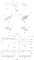
- the projections include but not limited to at least one of a ridge (shown in FIG. 4(c) ), a cylinder (shown in FIG. 4(f) ), a cylindrical tube
- FIG. 4(e) shows a cone (shown in FIG. 4(i) ), a truncated cone (shown in FIG. 4(j) ), a middle spherical frustum (shown in FIG. 4(p) ), an elliptic cylinder (shown in FIG. 4(n) ), a needle, a prism (shown in FIG. 4(k) ), a pyramid (shown in FIG. 4(I) ), a truncated pyramid (shown in FIG. 4(q) ), and a curve surface protrusion (shown in FIG. 4(b) and FIG. 4(o) ).
- the slots include slots penetrating the carrier unit, and/or slots not penetrating the carrier unit.
- the slots penetrating the carrier unit are configured in but not limited to comb shape, tooth shape and hollow-carved shape.
- the surface of the carrier unit in contact with the liquid membrane includes a plurality of rectangular slots not penetrating the carrier unit, the rectangular slots include a plurality of first rectangular slots, the long edges of the first rectangular slots are parallel to each other and perpendicular to the conveying direction of the liquid membrane.
- the size of the rectangular slot can be arranged according to the size of the obtained liquid membrane.
- the width of the rectangular slot is in the range from 0.5mm to 10.0mm.
- the width means the distance between the long edges of the rectangular slot.
- the width of the rectangular slot is in the range from 2.0mm to 5.0mm.
- the rectangular slots further include a plurality of second rectangular slots, the long edges of the second rectangular slots are parallel to each other and parallel to the conveying direction of the liquid membrane.
- the first rectangular slots and the second rectangular slots respectively restrict the relative movement between the liquid membrane and the carrier unit along directions parallel to and perpendicular to the conveying direction, and better prevent the liquid membrane from falling off due to shrinkage.
- At least one of the first rectangular slots connects with at least one of the second rectangular slots.
- This structure further benefits the liquid membrane entering into the slots, thereby increasing the contact force between the liquid membrane and the surface of the carrier unit, and meanwhile facilitating the liquid membrane to intimately contact with the first rectangular slots and the second rectangular slots after the liquid membrane shrinks due to it encounters the gelling solution. This prevents the liquid membrane from falling off or slipping due to shrinkage along the directions perpendicular to and parallel to the conveying direction.
- the carrier unit includes at least one opening in at least one of the short edges of the first rectangular slot.
- the carrier unit includes at least one opening in at least one of the short edges of the second rectangular slot.
- the opening structure is benefit for processing, and on the other hand, when the liquid membrane covers the short edge of the slot, the opening structure makes the liquid membrane at the short edge of the slot does not adhere to the carrier unit, thereby reducing the occurrence of membrane rupture at the edge of the carrier unit during removal of the liquid membrane.
- the first rectangular slots and the second rectangular slots are placed on the surface of the first carrier between an end close to the second carrier and an end away from the second carrier. This structure further increases the contact force between the liquid membrane and the surface of the carrier unit, and prevents the liquid membrane from falling off or slipping due to shrinkage along the directions perpendicular to and parallel to the conveying direction.
- the first rectangular slots and the second rectangular slots are placed on the surface of the second carrier between an end close to the first carrier and an end away from the first carrier.
- the liquid storage structures are kept in a liquid state in the conveying process.
- the slots are filled with liquid so that a carrier surface including at least one solid region and at least one liquid region is formed between the liquid membrane and the carrier unit.
- This structure further increases the friction between the liquid membrane and the surface of the carrier unit, and prevents the liquid membrane from falling off or slipping due to shrinkage along the directions perpendicular to and parallel to the conveying direction.
- the carrier surface since the carrier surface includes the liquid region, the subsequent peeling off of the porous membrane is further facilitated.
- the surface of the carrier unit is subjected but not limited to a wetting process so that the liquid storage structure is kept in a liquid state.
- the wetting process includes but not limited to spraying liquid to the surface of the carrier unit.
- the liquid sprayed to the surface of the carrier unit is water.
- the liquid sprayed to the surface of the carrier unit is a gelling solution with increased water content, that is, the water content in the liquid is greater than the water content in the gelling solution.
- the liquid membrane of the present disclosure refers to a liquid membrane-like substance formed by extruding a solution or slurry of a porous membrane from an extrusion die.
- the porous membrane solution or slurry can be made by mixing a raw material of porous membrane (high molecular polymer) with a solvent.
- the gelling solution includes a co-solvent, water, and a solvent that can dissolve the corresponding high molecular polymer.
- the water content in the gelling liquid is 30%, and the water content in the liquid is greater than 30%.
- the water content in the present embodiment is benefit for finishing the gelling process before the liquid membrane of present disclosure leaving the gelling solution.
- the solution or slurry of the porous membrane can be an aromatic polyamide solution formed by mixing an aromatic polyamide fiber, a solvent, and a co-solvent.
- the aromatic polyamide fibers are selected from aromatic polyamide staple fibers and/or aromatic polyamide fibrids.
- the solvent is selected from at least one of N-methylpyrrolidone (NMP), N,N-dimethylacetamide (DMAC), N,N-dimethylformamide (DMF), dimethylsulfoxide (DMSO) and triethyl phosphate (TEP).
- NMP N-methylpyrrolidone
- DMAC N,N-dimethylacetamide
- DMF N,N-dimethylformamide
- DMSO dimethylsulfoxide
- TEP triethyl phosphate
- the co-solvent is selected from at least one of sodium chloride, lithium chloride, calcium chloride, and magnesium chloride.
- the aromatic polyamide porous membrane may also be formed by a polymerization reaction of an aromatic polyamide solution.
- the present disclosure is not limited to the above selection.
- the liquid region may not be formed by spraying liquid on the surface of the carrier unit, but be formed by storing some of the gelling solution in the slots and/or the indentations of the projections of the carrier unit when the carrier unit passes through the gelling solution.
- the structures on the surface of the first carrier in contact with the liquid membrane may be the same as or different from the structures on the surface of the second carrier in contact with the liquid membrane.
- the first carrier and/or the second carrier may include at least one group (as shown in FIG. 8(d) ).
- the transmission unit includes a transmission plate.
- the transmission plate is a single-piece structure with less components and high reliability.
- the carrier unit is integrated with the transmission plate into a single piece, or the carrier unit is fixedly attached to the transmission plate.
- the transmission unit includes a driving wheel, a transmission chain and/or a transmission belt.
- the driving wheel drives the transmission chain or the transmission belt
- the carrier unit is located on the transmission belt or the transmission chain.
- the transmission unit includes at least two groups of transmission chains and/or transmission belts.
- the transmission unit further includes a supporting part for supporting the liquid membrane.
- the supporting part includes a supporting wheel, a roller or a gear.
- the conveying path of the liquid membrane can be changed, and the multi-level solidification or a multi-level cleaning can also be realized, i.e., let the liquid membrane pass through multi-levels of gelling solution pools with different concentrations (as shown in FIG. 10 ) or let the liquid membrane pass through multiple cleaning pools.
- the multi-level solidification could control the gelling time by controlling the water content of the gelling solutions of each level, thereby realizing the quality control of the porous membrane according to requirements.
- the carrier unit is located on a chain link of the transmission chain.
- the carrier unit is integrated with the chain link of the transmission chain into a single piece or the carrier unit is fixedly attached to the chain link of the transmission chain.
- the chain link includes a link plate.
- the carrier unit is integrated with the link plate into a single piece or the carrier unit is fixedly attached to the link plate.
- the carrier unit is integrated with the transmission belt into a single piece or the carrier unit is fixedly attached to the transmission belt.
- the surface of the first carrier in contact with the liquid membrane has an arbitrary point A
- the surface of the second carrier in contact with the liquid membrane has an arbitrary point B
- in a liquid membrane conveying process of the liquid membrane the distance between the point A and the point B is changed.
- the width of the liquid membrane can be designed according to actual requirements. For example, when the liquid membrane is casted to the carrier unit and enters into the gelling solution with the carrier unit, the width of the liquid membrane becomes larger, which can prevent or compensate the shrinkage of the liquid membrane in the gelling solution along the directions perpendicular to and parallel to the conveying direction. When the liquid membrane is about to leave the gelling solution, the width of the liquid membrane becomes smaller, which can provide a buffer before the liquid membrane is further stretched.
- a line connecting the point A with the point B perpendiculars to the conveying direction of the liquid membrane.
- the minimum distance between point A and point B is L
- the maximum distance between point A and point B is L'
- the ratio between the minimum distance L and the maximum distance L' is 1:1 to 1:1.2.
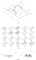
- FIG. 1 shows a liquid membrane conveying apparatus for preparing a porous membrane according to an embodiment of the present disclosure.
- the liquid membrane conveying apparatus includes a transmission unit 1 and a carrier unit 2.
- the transmission unit 1 includes a driving wheel 11 and a transmission belt 12.
- the carrier unit 2 includes a first carrier 21 and a second carrier 22.
- the carrier unit 2 is located on the transmission belt 12 and integrated with the transmission belt 12 into a single piece.
- the first carrier 21 and the second carrier 22 of the carrier unit 2 respectively contact with opposite edges of the liquid membrane 3 along a conveying direction of the liquid membrane 3. Under the entrainment of the transmission unit 1, the carrier unit 2 conveys the liquid membrane 3 into a gelling solution 4 to perform gel curing.
- FIG. 1 shows a liquid membrane conveying apparatus for preparing a porous membrane according to an embodiment of the present disclosure.
- the liquid membrane conveying apparatus includes a transmission unit 1 and a carrier unit 2.
- the transmission unit 1 includes a driving wheel 11 and a transmission belt 12.
- the carrier unit 2 includes a first carrier 21 and a second carrier 22.
- the carrier unit 2 is located on the transmission belt 12 and integrated with the transmission belt 12 into a single piece.
- a surface of the carrier unit 2 is a planar smooth surface.
- the first carrier 21 and the second carrier 22 of the carrier unit 2 respectively contact with opposite edges of the liquid membrane 3 along a conveying direction of the liquid membrane 3. Under the entrainment of the transmission unit 1, the carrier unit 2 conveys the liquid membrane 3 into a gelling solution 4 to perform gel curing.
- Embodiment 3 is substantially the same as embodiment 2. The difference from embodiment 3 and embodiment 2 is that the surface of the carrier unit 2 of embodiment 3 is a rough surface with a roughness Ra of 1000.
- FIG. 1 shows a liquid membrane conveying apparatus for preparing a porous membrane according to an embodiment of the present disclosure.
- the liquid membrane conveying apparatus includes a transmission unit 1 and a carrier unit 2.
- the transmission unit 1 includes a driving wheel 11 and a transmission belt 12.
- the carrier unit 2 includes a first carrier 21 and a second carrier 22.
- the carrier unit 2 is located on the transmission belt 12 and integrated with the transmission belt 12 into a single piece.
- a surface of the carrier unit 2 includes a plurality of smooth regions and a plurality of rough regions alternately distributed with the smooth regions (the rough region is shown as the shadow region in the figure), and the rough region has a roughness Ra of 800.
- the first carrier 21 and the second carrier 22 of the carrier unit 2 respectively contact with opposite edges of the liquid membrane 3 along a conveying direction of the liquid membrane 3.
- the carrier unit 2 conveys the liquid membrane 3 into a gelling solution 4 to perform gel curing.
- a liquid membrane conveying apparatus for preparing a porous membrane of the present disclosure includes a transmission unit 1 and a carrier unit 2.
- the transmission unit 1 includes a driving wheel 11, a transmission belt 12 and a supporting part 14.
- the supporting part 14 is a roller placed under the transmission belt 12.
- the carrier unit 2 includes a first carrier 21 and a second carrier 22.
- the carrier unit 2 is located on the transmission belt 12 and fixedly fixed to the transmission belt 12.
- the first carrier 21 and the second carrier 22 of the carrier unit 2 respectively contact with opposite edges of the liquid membrane 3 along a conveying direction of the liquid membrane 3. Under the entrainment of the transmission unit 1, the carrier unit 2 conveys the liquid membrane 3 into a gelling solution 4 to perform gel curing.
- two fixing structures such as two clips 24 for fixing the two edges of the liquid membrane 3 are provided, and the clips 24 are fixedly connected to the carrier unit 2.
- a liquid membrane conveying apparatus for preparing a porous membrane of the present disclosure includes a transmission unit 1 and a carrier unit 2.
- the transmission unit 1 includes a driving wheel 11, a transmission belt 12 and a supporting part 14.
- the supporting part 14 is a supporting wheel placed under the transmission belt 12.
- the carrier unit 2 includes a first carrier 21 and a second carrier 22.
- the carrier unit 2 is located on the transmission belt 12 and fixedly attached to the transmission belt 12.
- the first carrier 21 and the second carrier 22 of the carrier unit 2 respectively contact with opposite edges of the liquid membrane 3 along a conveying direction of the liquid membrane 3. Under the entrainment of the transmission unit 1, the carrier unit 2 conveys the liquid membrane 3 into a gelling solution 4 to perform gel curing.
- two fixing structures such as two clips 24 for fixing the two edges of the liquid membrane 3 are provided, and the clips 24 are integrated with the carrier unit 2 into a single piece.
- the area where the first carrier 21 contacts with the liquid membrane 3 accounts for 0.1% of the total area of the liquid membrane 3
- the area where the second carrier 22 contacts with the liquid membrane 3 accounts for 0.1% of the total area of the liquid membrane 3.
- FIG. 2 shows a liquid membrane conveying apparatus for preparing a porous membrane of the present disclosure.
- the liquid membrane conveying apparatus includes a transmission unit 1 and a carrier unit 2.
- the transmission unit 1 includes a driving wheel 11, a transmission chain 13, and a supporting part 14.
- the supporting part 14 is a gear.
- the carrier unit 2 includes a first carrier 21 and a second carrier 22.
- the transmission chain 13 includes a plurality of chain links, and the carrier unit 2 is integrated with the chain links into a single piece.
- the first carrier 21 and the second carrier 22 of the carrier unit 2 respectively contact with opposite edges of the liquid membrane 3 along a conveying direction of the liquid membrane 3, so that the whole carrier unit 2 are in contact with the edges of the liquid membrane 3, and the boundaries of the carrier unit 2 are aligned with the boundaries of the liquid membrane 3, as shown in FIG. 8(b) .
- the carrier unit 2 conveys the liquid membrane 3 into a gelling solution 4 to perform gel curing.
- a plurality of needles 23 for fixing the two edges of the liquid membrane are provided, and the needles 23 are integrated with the carrier unit 2 into a single piece.
- the area where the first carrier 21 which contacts with the liquid membrane 3 accounts for 10.0% of the total area of the liquid membrane 3, and the area where the second carrier 22 contacts with the liquid membrane 3 accounts for 10.0% of the total area of the liquid membrane 3.
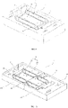
- FIG. 3 shows a liquid membrane conveying apparatus for preparing a porous membrane of the present disclosure.
- the liquid membrane conveying apparatus includes a transmission unit 1 and a carrier unit 2.
- the transmission unit 1 includes a transmission plate 15.
- the carrier unit 2 includes a first carrier 21 and a second carrier 22, and the carrier unit 2 is fixed on the transmission plate 15.
- a surface of the carrier unit 2 includes a plurality of smooth regions and a plurality of rough regions alternately distributed with the smooth regions (the rough region is shown as the shadow region in the figure), and the rough region has a roughness Ra of 100.
- the first carrier 21 and the second carrier 22 of the carrier unit 2 respectively contact with opposite edges of the liquid membrane 3 along a conveying direction of the liquid membrane 3 so that the whole carrier unit 2 are in contact with the edges of the liquid membrane 3, and the boundaries of the liquid membrane 3 extend beyond the boundaries of the carrier unit 2, as shown in FIG. 8(c) .
- the carrier unit 2 conveys the liquid membrane 3 into a gelling solution 4 to perform gel curing.
- the area where the first carrier 21 contacts with the liquid membrane 3 accounts for 20.0% of the total area of the liquid membrane 3, and the area where the second carrier 22 contacts with the liquid membrane 3 accounts for 20.0% of the total area of the liquid membrane 3.
- FIG. 10 shows a liquid membrane conveying apparatus for preparing a porous membrane of the present disclosure.
- the liquid membrane conveying apparatus includes a transmission unit 1 and a carrier unit 2.
- the transmission unit 1 includes a driving wheel 11, a transmission belt 12 and a supporting part 14.
- the supporting part 14 is a supporting wheel.
- the carrier unit 2 includes a first carrier 21 and a second carrier 22.
- the carrier unit 2 is located on the transmission belt 12 and integrated with the transmission belt 12 into a single piece.
- a surface of the carrier unit 2 includes a plurality of smooth regions and a plurality of rough regions alternately distributed with the smooth regions (the rough region is shown as the shadow region in the figure), and the rough region has a roughness Ra of 500.
- FIG. 4(s) a surface of the carrier unit 2 includes a plurality of smooth regions and a plurality of rough regions alternately distributed with the smooth regions (the rough region is shown as the shadow region in the figure), and the rough region has a roughness Ra of 500.
- the first carrier 21 and the second carrier 22 of the carrier unit 2 respectively contact with opposite edges of the liquid membrane 3 along a conveying direction of the liquid membrane 3, with a portion of the carrier unit 2 contacting with the edges of the liquid membrane 3, and the other portion of the carrier unit 2 extending beyond the liquid membrane 3.
- the carrier unit 2 conveys the liquid membrane 3 into a gelling solution 4 to perform gel curing.
- the gelling solution 4 includes two regions having different water contents.
- the two regions are respectively located in two adjacent and isolated gelling pools, i.e., a first gelling pool 61 and a second gelling pool 62.
- the water content of the gelling solution in the first gelling pool 61 is 30%, and the water content of the gelling solution in the second gelling pool 62 is 50%.
- the supporting part 14 is located above the adjacent interface of the first gelling pool 61 and the second gelling pool 62.
- the transport path of the liquid membrane 3 is changed by the supporting parts 14, and by the support of the supporting parts 14, the carrier unit 2 conveys the liquid membrane 3 passing through the gelling solution 4 in the first gelling pool 61 and then entering in the gelling solution 4 in the second gelling pool 62.
- a liquid membrane conveying apparatus for preparing a porous membrane of the present disclosure includes a transmission unit 1 and a carrier unit 2.
- the transmission unit 1 includes a driving wheel 11, a transmission belt 12 and a supporting part 14.
- the supporting part 14 is a supporting wheel.
- the carrier unit 2 includes a first carrier 21 and a second carrier 22.
- the carrier unit 2 is located on the transmission belt 12 and integrated with the transmission belt 12 into a single piece. As shown in FIG.
- the first carrier 21 and the second carrier 22 of the carrier unit 2 respectively contact with opposite edges of the liquid membrane 3 along a conveying direction of the liquid membrane 3, with a portion of the carrier unit 2 contacting with the edges of the liquid membrane 3, and the other portion of the carrier unit 2 extending beyond the liquid membrane 3.
- the carrier unit 2 conveys the liquid membrane 3 into a gelling solution 4 to perform gel curing.
- An anti-slip structure is provided on a surface of the carrier unit 2 which contacts with the liquid membrane 3, and the anti-slip structure is a ridge as shown in FIG. 4(c) . Therefore, as shown in FIGS. 5(a) and 5(b) , when the carrier unit 2 contacts with the liquid membrane 3, a carrier surface 5 with a solid region 51 and a non-solid region 52 is formed. The area ratio of the solid region 51 and the non-solid region 52 is 7:3. There is no liquid in the non-solid region 52 and the non-solid region 52 is regarded as a gas region.
- the area where the first carrier 21 contacts with the liquid membrane 3 accounts for 35.0% of the total area of the liquid membrane 3, and the area where the second carrier 22 contacts with the liquid membrane 3 accounts for 35.0% of the total area of the liquid membrane 3.
- Embodiment 11 is substantially the same as embodiment 10. The difference from embodiment 11 and embodiment 10 is that the anti-slip structure in embodiment 11 is a diamond-shaped projection as shown in FIG. 4(g) .
- Embodiment 12 is substantially the same as embodiment 10. The difference from embodiment 11 and embodiment 10 is that the anti-slip structure in embodiment 12 is a circular recess as shown in FIG. 4(d) .
- Embodiment 13 is substantially the same as embodiment 12. The difference from embodiment 13 and embodiment 12 is that except for the portion with circular recess, the other portion of the surface of the carrier unit 2 is rough surface with a roughness Ra of 200.
- a liquid membrane conveying apparatus for preparing a porous membrane of the present disclosure includes a transmission unit 1 and a carrier unit 2.
- the transmission unit 1 includes a driving wheel 11, a transmission belt 12 and a supporting part 14.
- the supporting part 14 is a supporting wheel.
- the carrier unit 2 includes a first carrier 21 and a second carrier 22.
- the carrier unit 2 is located on and fixed to the transmission belt 12. As shown in FIG. 1 ,
- the first carrier 21 and the second carrier 22 of the carrier unit 2 respectively contact with opposite edges of the liquid membrane 3 along a conveying direction of the liquid membrane 3, with a portion of the carrier unit 2 contacting with the edges of the liquid membrane 3, and the other portion of the carrier unit 2 extending beyond the liquid membrane 3.
- the carrier unit 2 conveys the liquid membrane 3 into a gelling solution 4 to perform gel curing.
- a plurality of liquid storage structures are provided, and the liquid storage structures are rectangular slots as shown in FIG. 4(h) . Therefore, as shown in FIG. 5 , when the carrier unit 2 contacts with the liquid membrane 3, a carrier surface 5 with a solid region 51 and a non-solid region 52 is formed.
- the area ratio of the solid region 51 and the non-solid region 52 is 1:9.
- the liquid storage structure carries gelling solution when the carrier unit 2 leaves the gelling solution, therefore, the non-solid region 52 stores liquid therein and the non-solid region 52 is regarded as a liquid region.
- the area where the first carrier 21 contacts the liquid membrane 3 accounts for 0.5% of the total area of the liquid membrane 3, and the area where the second carrier 22 contacts the liquid membrane 3 accounts for 0.5% of the total area of the liquid membrane 3.
- a liquid membrane conveying apparatus for preparing a porous membrane of the present disclosure includes a transmission unit 1 and a carrier unit 2.
- the transmission unit 1 includes a driving wheel 11, a transmission belt 12 and a supporting part 14.
- the supporting part 14 is a supporting wheel.
- the carrier unit 2 includes two groups of parallel first carriers 21 and two groups of parallel second carriers 22.
- the carrier unit 2 is located on the transmission belt 12 and integrated with the transmission belt 12 into a single piece. As shown in FIG.
- the first carrier 21 and the second carrier 22 of the carrier unit 2 respectively contact with opposite edges of the liquid membrane 3 along a conveying direction of the liquid membrane 3, with the whole carrier unit 2 contacting with the edges of the liquid membrane 3, and the boundaries of the liquid membrane 3 extending beyond boundaries of the carrier unit 2.
- the carrier unit 2 conveys the liquid membrane 3 into a gelling solution 4 to perform gel curing.
- the water content of the gelling solution is 30%.
- a carrier surface 5 with a solid region 51 and a non-solid region 52 is formed on a surface of the carrier unit 2 in contact with the liquid membrane 3.
- the area ratio of the solid region 51 and the non-solid region 52 is 6:4.
- the surface of the carrier unit 2 is subjected to a wetting process, and a gelling solution having a water content of 50% is sprayed to the surface so that the non-solid region 52 is in a liquid state and is regarded as a liquid region.
- the area of the first carrier 21 in contact with the liquid membrane 3 accounts for 5.0% of the total area of the liquid membrane 3, and the area of the second carrier 22 in contact with the liquid membrane 3 accounts for 5.0% of the total area of the liquid membrane 3.
- Embodiment 16 is substantially the same as embodiment 15. The difference from embodiment 16 and embodiment 15 is that, when the surface of the carrier unit 2 is subjected to a wetting process, the fluid being sprayed to the surface is water.
- Another liquid membrane conveying apparatus for preparing a porous membrane of the present disclosure includes a transmission unit 1 and a carrier unit 2.
- the transmission unit 1 includes a driving wheel 11, a transmission chain 13, and a supporting part 14.
- the supporting part 14 is a gear.
- the carrier unit 2 includes a first carrier 21 and a second carrier 22.
- the transmission chain 13 includes a plurality of chain links, the chain link includes a link plate, and the carrier unit 2 is integrated with the link plates into a single piece. As shown in FIG.
- the first carrier 21 and the second carrier 22 of the carrier unit 2 respectively contact with opposite edges of the liquid membrane 3 along a conveying direction of the liquid membrane 3, with the whole carrier unit 2 contacting with the edges of the liquid membrane 3, and the boundaries of the carrier unit 2 aligning with the boundaries of the liquid membrane 3.
- the carrier unit 2 conveys the liquid membrane 3 into a gelling solution 4 to perform gel curing.
- a plurality of spaced first rectangular slots not penetrating the carrier unit 2 are provided on a surface of the carrier unit 2 in contact with the liquid membrane 3.
- a carrier surface 5 with a solid region 51 and a non-solid region 52 is formed.
- the long edges of the first rectangular slots are parallel to each other and perpendicular to the conveying direction of the liquid membrane 3.
- the width of the first rectangular slot is 10.0mm.
- the area where the first carrier 21 contacts with the liquid membrane 3 accounts for 1.0% of the total area of the liquid membrane 3.
- the area where the second carrier 22 contacts with the liquid membrane 3 accounts for 1.0% of the total area of the liquid membrane 3.
- Embodiment 18 is substantially the same as embodiment 17. The difference from embodiment 18 and embodiment 17 is that the width of the first rectangular slot is 1.0mm.
- a liquid membrane conveying apparatus for preparing a porous membrane of the present disclosure includes a transmission unit 1 and a carrier unit 2.
- the transmission unit 1 includes a driving wheel 11, a transmission chain 13, and a supporting part 14.
- the supporting part 14 is a gear.
- the carrier unit 2 includes a first carrier 21 and a second carrier 22.
- the carrier unit 2 is located on and fixedly attached to the transmission chain 13. As shown in FIG.
- the first carrier 21 and the second carrier 22 of the carrier unit 2 respectively contact with opposite edges of the liquid membrane 3 along a conveying direction of the liquid membrane 3, with a portion of the carrier unit 2 contacting with the edges of the liquid membrane 3, and the other portion of the carrier unit 2 extending beyond the boundaries of the liquid membrane 3.
- the carrier unit 2 conveys the liquid membrane 3 into a gelling solution 4 to perform gel curing.
- the water content of the gelling solution 4 is 30%.
- a plurality of spaced first rectangular slots not penetrating the carrier unit 2 are provided on a surface of the carrier unit 2 in contact with the liquid membrane 3.
- the long edges of the first rectangular slots are parallel to each other and perpendicular to the conveying direction of the liquid membrane 3.
- the width of the first rectangular slot is 4.0mm.
- a plurality of spaced second rectangular slots are also provided on a surface of the carrier unit 2 in contact with the liquid membrane 3.
- the long edges of the second rectangular slots are parallel to each other and parallel to the conveying direction of the liquid membrane 3.
- the width of the second rectangular slot is 5.0mm.
- a gelling solution having a water content of 40% is sprayed on the surface of the carrier unit 2, and a carrier surface 5 with a solid region 51 and a non-solid region 52 as shown in FIG. 5 is formed, wherein the non-solid region 52 is regarded as a liquid region.
- the area where the first carrier 21 contacts with the liquid membrane 3 accounts for 0.8% of the total area of the liquid membrane 3.
- the area where the second carrier 22 contacts with the liquid membrane 3 accounts for 0.8% of the total area of the liquid membrane 3.
- a liquid membrane conveying apparatus for preparing a porous membrane of the present disclosure includes a transmission unit 1 and a carrier unit 2.
- the transmission unit 1 includes a driving wheel 11, a transmission chain 13, and a supporting part 14.
- the supporting part 14 is a gear.
- the carrier unit 2 includes a first carrier 21 and a second carrier 22.
- the carrier unit 2 is located on and fixedly attached to the transmission chain 13. As shown in FIG.
- the first carrier 21 and the second carrier 22 of the carrier unit 2 respectively contact with opposite edges of the liquid membrane 3 along a conveying direction of the liquid membrane 3, with a portion of the carrier unit 2 contacting with the edges of the liquid membrane 3, and the other portion of the carrier unit 2 extending beyond the boundaries of the liquid membrane 3.
- the carrier unit 2 conveys the liquid membrane 3 into a gelling solution 4 to perform gel curing.
- the water content of the gelling solution 4 is 30%.
- a plurality of spaced first rectangular slots not penetrating the carrier unit 2 are provided on a surface of the carrier unit 2 in contact with the liquid membrane 3.
- a plurality of spaced first rectangular slots and a plurality of spaced second rectangular slots are placed on the surface of the first carrier 21 between a position close to the second carrier 22 and a position away from the second carrier 22.
- a plurality of first rectangular slots and a plurality of second rectangular slots are placed on the surface of the second carrier 22 between a position close to the first carrier 21 and a position away from the first carrier 21.
- the first rectangular slot connects with the nearest second rectangular slot.
- a gelling solution having a water content of 40% is sprayed on the surface of the carrier unit 2, and a carrier surface 5 with a solid region 51 and a non-solid region 52 as shown in FIG. 5 is accordingly formed, wherein the non-solid region 52 is regarded as a liquid region.
- the area where the first carrier 21 contacts with the liquid membrane 3 accounts for 0.8% of the total area of the liquid membrane 3.
- the area where the second carrier 22 contacts with the liquid membrane 3 accounts for 0.8% of the total area of the liquid membrane 3.
- a liquid membrane conveying apparatus for preparing a porous membrane of the present disclosure includes a transmission unit 1 and a carrier unit 2.
- the transmission unit 1 includes a driving wheel 11, a transmission belt 12, and a supporting part 14.
- the supporting part 14 is a gear.
- the carrier unit 2 includes a first carrier 21 and a second carrier 22. As shown in FIG. 7(a) , the carrier unit 2 is located on the transmission belt 12 and integrated with the transmission belt 12 into a single piece. As shown in FIG.
- the first carrier 21 and the second carrier 22 of the carrier unit 2 respectively contact with opposite edges of the liquid membrane 3 along a conveying direction of the liquid membrane 3, with a portion of the carrier unit 2 contacting with the edges of the liquid membrane 3, and the other portion of the carrier unit 2 extending beyond the boundaries of the liquid membrane 3.
- the carrier unit 2 conveys the liquid membrane 3 into a gelling solution 4 to perform gel curing.
- a plurality of spaced rectangular slots penetrating the carrier unit 2 are provided on a surface of the carrier unit 2 in contact with the liquid membrane 3.
- An end of the rectangular slot is opened and the carrier unit 2 is configured in comb-shape.
- the long edges of the rectangular slot are parallel to each other and perpendicular to the conveying direction of the liquid membrane 3.
- the width of the rectangular slot is 3.0 mm.
- the edges of the liquid membrane 3 is in contact with the carrier unit 2, forming a carrier surface 5 (shown in FIG. 5 ) having a solid region 51 and a non-solid region 52.
- the solid region 51 and the non-solid region 52 are arranged in an alternate manner, and the non-solid region 52 is regarded as a gas region.
- the area where the first carrier 21 contacts with the liquid membrane 3 accounts for 1.0% of the total area of the liquid membrane 3.
- the area where the second carrier 22 contacts with the liquid membrane 3 accounts for 1.0% of the total area of the liquid membrane 3.
- a liquid membrane conveying apparatus for preparing a porous membrane of the present disclosure includes a transmission unit 1 and a carrier unit 2.
- the transmission unit 1 includes a driving wheel 11, a transmission belt 12, and a supporting part 14.
- the supporting part 14 is a gear.
- the carrier unit 2 includes a first carrier 21 and a second carrier 22. As shown in FIG. 7(b) , the carrier unit 2 is located on and fixedly attached to the transmission belt 12 by screws. As shown in FIG.
- the first carrier 21 and the second carrier 22 of the carrier unit 2 respectively contact with opposite edges of the liquid membrane 3 along a conveying direction of the liquid membrane 3, with a portion of the carrier unit 2 contacting with the edges of the liquid membrane 3, and the other portion of the carrier unit 2 extending beyond the boundaries of the liquid membrane 3.
- the carrier unit 2 conveys the liquid membrane 3 into a gelling solution 4 to perform gel curing.
- a plurality of spaced rectangular slots penetrating the carrier unit 2 are provided on a surface of the carrier unit 2 in contact with the liquid membrane 3.
- An end of the rectangular slot is opened and the carrier unit 2 is configured in comb-shape.
- the long edges of the rectangular slot are parallel to each other and perpendicular to the conveying direction of the liquid membrane 3.
- the width of the rectangular slot is 3.0 mm.
- the edges of the liquid membrane 3 is in contact with the carrier unit 2, forming a carrier surface 5 (shown in FIG. 5 ) having a solid region 51 and a non-solid region 52.
- the solid region 51 and the non-solid region 52 are arranged in an alternate manner, and the non-solid region 52 is regarded as a gas region.
- the area where the first carrier 21 contacts with the liquid membrane 3 accounts for 4.0% of the total area of the liquid membrane 3.
- the area where the second carrier 22 contacts with the liquid membrane 3 accounts for 4.0% of the total area of the liquid membrane 3.
- a liquid membrane conveying apparatus for preparing a porous membrane of the present disclosure includes a transmission unit 1 and a carrier unit 2.
- the transmission unit 1 includes a driving wheel 11, a transmission chain 13, and a supporting part 14.
- the supporting part 14 is a gear.
- the carrier unit 2 includes a first carrier 21 and a second carrier 22.
- the carrier unit 2 is located on the transmission chain 13. As shown in FIG. 7(c) , the carrier unit 2 is integrated with chain links 131 of the transmission chain 13 into a single piece. As shown in FIG.
- the first carrier 21 and the second carrier 22 of the carrier unit 2 respectively contact with opposite edges of the liquid membrane 3 along a conveying direction of the liquid membrane 3, with a portion of the carrier unit 2 contacting with the edges of the liquid membrane 3, and the other portion of the carrier unit 2 extending beyond the boundaries of the liquid membrane 3.
- the carrier unit 2 conveys the liquid membrane 3 into a gelling solution 4 to perform gel curing.
- a plurality of spaced rectangular slots penetrating the carrier unit 2 are provided on a surface of the carrier unit 2 in contact with the liquid membrane 3.
- An end of the rectangular slot is opened and the carrier unit 2 is configured in comb-shape.
- the long edges of the rectangular slot are parallel to each other and perpendicular to the conveying direction of the liquid membrane 3.
- the width of the rectangular slot is 3.0 mm.
- the edges of the liquid membrane 3 is in contact with the carrier unit 2, forming a carrier surface 5 (shown in FIG. 5 ) having a solid region 51 and a non-solid region 52.
- the surface of the carrier unit 2 is subjected to a wetting process, and water is sprayed to the surface so that the non-solid region 52 is in a liquid state and is regarded as a liquid region.
- the area where the first carrier 21 contacts with the liquid membrane 3 accounts for 15.0% of the total area of the liquid membrane 3.
- the area where the second carrier 22 contacts with the liquid membrane 3 accounts for 15.0% of the total area of the liquid membrane 3.
- a liquid membrane conveying apparatus for preparing a porous membrane of the present disclosure includes a transmission unit 1 and a carrier unit 2.
- the transmission unit 1 includes a driving wheel 11, a transmission chain 13, and a supporting part 14.
- the supporting part 14 is a gear.
- the carrier unit 2 includes a first carrier 21 and a second carrier 22.
- the carrier unit 2 is located on the transmission chain 13. As shown in FIG. 7(d) , the carrier unit 2 is fixedly attached to chain links 131 of the transmission chain 13 by screws. As shown in FIG.
- the first carrier 21 and the second carrier 22 of the carrier unit 2 respectively contact with opposite edges of the liquid membrane 3 along a conveying direction of the liquid membrane 3, with a portion of the carrier unit 2 contacting with the edges of the liquid membrane 3, and the other portion of the carrier unit 2 extending beyond the boundaries of the liquid membrane 3.
- the carrier unit 2 conveys the liquid membrane 3 into a gelling solution 4 to perform gel curing.
- a plurality of spaced rectangular slots penetrating the carrier unit 2 are provided on a surface of the carrier unit 2 in contact with the liquid membrane 3.
- An end of the rectangular slot is opened and the carrier unit 2 is configured in comb-shape.
- the long edges of the rectangular slot are parallel to each other and perpendicular to the conveying direction of the liquid membrane 3.
- the width of the rectangular slot is 2.0 mm.
- the edges of the liquid membrane 3 is in contact with the carrier unit 2, forming a carrier surface 5 (shown in FIG. 5 ) having a solid region 51 and a non-solid region 52.
- the surface of the carrier unit 2 is subjected to a wetting process, and water is sprayed to the surface so that the non-solid region 52 is in a liquid state and is regarded as a liquid region.
- the area where the first carrier 21 contacts with the liquid membrane 3 accounts for 1.0% of the total area of the liquid membrane 3.
- the area where the second carrier 22 contacts with the liquid membrane 3 accounts for 1.0% of the total area of the liquid membrane 3.
- a liquid membrane conveying apparatus for preparing a porous membrane of the present disclosure includes a transmission unit 1 and a carrier unit 2.
- the transmission unit 1 includes a driving wheel 11, a transmission chain 13, and a supporting part 14.
- the supporting part 14 is a gear.
- the carrier unit 2 includes a first carrier 21 and a second carrier 22.
- the carrier unit 2 is located on and fixedly attached to the transmission chain 13. As shown in FIG.
- the first carrier 21 and the second carrier 22 of the carrier unit 2 respectively contact with opposite edges of the liquid membrane 3 along a conveying direction of the liquid membrane 3, with a portion of the carrier unit 2 contacting with the edges of the liquid membrane 3, and the other portion of the carrier unit 2 extending beyond the boundaries of the liquid membrane 3.
- the carrier unit 2 conveys the liquid membrane 3 into a gelling solution 4 to perform gel curing.
- a plurality of spaced first rectangular slots penetrating the carrier unit 2 are provided on a surface of the carrier unit 2 in contact with the liquid membrane 3.
- the long edges of the first rectangular slots are parallel to each other and perpendicular to the conveying direction of the liquid membrane 3.
- the width of the first rectangular slot is 4.0 mm.
- a plurality of spaced second rectangular slots penetrating the carrier unit 2 are provided on a surface of the carrier unit 2 in contact with the liquid membrane 3.
- the long edges of the second rectangular slots are parallel to each other and perpendicular to the conveying direction of the liquid membrane 3.
- the width of the second rectangular groove is 5.0 mm.
- a plurality of first rectangular slots and a plurality of second rectangular slots are placed on the surface of the first carrier 21 between a position close to the second carrier 22 and a position away from the second carrier 22, respectively.
- a plurality of first rectangular slots and a plurality of second rectangular slots are placed on the surface of the second carrier 22 between a position close to the first carrier 21 and a position away from the first carrier 21, respectively.
- the first rectangular groove does not connect with the nearest second rectangular groove.
- the short edges of the first rectangular slots and the second rectangular groove are not open, and the carrier unit 2 is configured in a hollow-carved frame.
- the edges of the liquid membrane 3 is in contact with the carrier unit 2, forming a carrier surface 5 (shown in FIG. 5 ) having a solid region 51 and a non-solid region 52.
- the surface of the carrier unit 2 is subjected to a wetting process, and water is sprayed to the surface so that the non-solid region 52 is in a liquid state and is regarded as a liquid region.
- the area where the first carrier 21 contacts with the liquid membrane 3 accounts for 0.5% of the total area of the liquid membrane 3.
- the area where the second carrier 22 contacts with the liquid membrane 3 accounts for 0.5% of the total area of the liquid membrane 3.
- a liquid membrane conveying apparatus for preparing a porous membrane of the present disclosure includes a transmission unit 1 and a carrier unit 2.
- the transmission unit 1 includes a driving wheel 11, a transmission chain 13, and a supporting part 14.
- the supporting part 14 is a gear.
- the carrier unit 2 includes a first carrier 21 and a second carrier 22.
- the carrier unit 2 is located on and fixedly attached to the transmission chain 13. As shown in FIG.
- the first carrier 21 and the second carrier 22 of the carrier unit 2 respectively contact with opposite edges of the liquid membrane 3 along a conveying direction of the liquid membrane 3, with a portion of the carrier unit 2 contacting with the edges of the liquid membrane 3, and the other portion of the carrier unit 2 extending beyond the boundaries of the liquid membrane 3.
- the carrier unit 2 conveys the liquid membrane 3 into a gelling solution 4 to perform gel curing.
- the liquid membrane conveying apparatus has a plurality of carrier units 2 in contact with the liquid membrane 3, and the surfaces of the carrier units 2 are provided with different surface structures as shown in FIG. 4 .
- the carrier units 2 having the different groups, each with the same surface structures, are arranged in and are sequentially arranged on the transmission chain 13.
- Embodiment 27 is substantially the same as embodiment 26.
- the difference from embodiment 27 and embodiment 26 is that the carrier units 2 have the different surface structures and are disorderly arranged on the transmission chain 13.
- Embodiment 28 is substantially the same as embodiment 21.
- the difference from embodiment 28 and embodiment 21 is that, in this embodiment, as shown in FIG. 9 , the surface of the first carrier 21 in contact with the liquid membrane 3 has an arbitrary point A, the surface of the second carrier 22 in contact with the liquid membrane 3 has an arbitrary point B, and a line connecting the point A with the point B perpendiculars to the conveying direction of the liquid membrane 3.
- the distance between the point A and the point B is changed by changing the movement path of the carrier unit 2, and the width of the carried liquid membrane 3 is accordingly changed.
- the minimum distance between point A and point B is L
- the maximum distance between point A and point B is L'
- the ratio between the minimum distance L and the maximum distance L' is 1:1.2.
Landscapes
- Chemical & Material Sciences (AREA)
- Chemical Kinetics & Catalysis (AREA)
- Engineering & Computer Science (AREA)
- Manufacturing & Machinery (AREA)
- Dispersion Chemistry (AREA)
- Separation Using Semi-Permeable Membranes (AREA)
Description
- The present application is based on and claims priority of
Chinese Patent Application No. 201710556987.9, filed on July 10, 2017 - The present disclosure relates to a liquid membrane conveying apparatus for preparing a porous membrane.
- The methods for preparing porous membranes mainly include non-solvent induced phase separation, thermally induced phase separation and evaporation induced phase separation methods. The non-solvent induced phase separation method forms the porous membrane by controlling the liquid-liquid phase separation of the polymer solution. In the process of preparing the porous membrane by the non-solvent induced phase separation method, the polymer solution membrane (i.e., the liquid membrane) needs to fully contact with the gelling solution to improve the porosity and pore quality of the porous membrane.
- Presently, in the process of preparing the porous membrane by the non-solvent induced phase separation method, the liquid membrane is extruded on a steel belt or the like from an extrusion die, and the movement of the liquid membrane in the gelling solution is driven by the steel belt or the like. In this process, one surface of the liquid membrane fully contacts with the gelling solution, while the other surface of the liquid membrane could not in close contact with the gelling solution due to the other surface is in close contact with the steel belt. Therefore, the other surface of the liquid membrane has poor pore forming condition and low porosity, and even forming closed pores on this surface. This results the pore structures on the two opposite surfaces of the obtained porous membrane be asymmetry, and further affects the quality of the porous membrane.
-
US2014077405A1 discloses devices and methods of manufacturing a polyolefin micro-porous film. An exemplary device includes a movement mechanism having a constraining means capable of mechanically constraining both widthwise edge parts of the strip-like and film-like micro-porous film precursor in the drying chamber; a drying means and a liquid seal tank. An exemplary method includes a step for mechanically constraining both widthwise edge parts of the strip-like and film-like micro-porous film precursor and a step for conveying the foregoing film precursor into the drying chamber. Another exemplary method includes a step for mechanically constraining both widthwise edge parts of the strip-like and film-like micro-porous film precursor at an entrance side of the drying chamber, a step for commencing extracting of the plasticizer from the film-like micro-porous film precursor, and a step for conveying the strip-like and film-like micro-porous film precursor into the drying chamber and for heating the foregoing film precursor. -
US2003224113A1 discloses a solution film-forming method which includes the steps of: forming a film from a polymer solution in which a polymer is dissolved in an organic solvent transporting the film formed, and passing the film through a drying area in which the film is heated to volatilize the organic solvent in the film to obtain a polymer film, wherein the film is passed through the drying area under the condition of -0.05≤ ∈MD-∈TD<+0.15 , where a degree of stretching of the film in the transport direction within the drying area during transport is expressed as ∈MD and a degree of stretching of the film in the width direction within the drying area during transport is expressed as ∈TD. -
US8932509 discloses a method of producing a solid electrolyte membrane, the method comprising steps of: (a) casting a dope containing a solid electrolyte and an organic solvent from a casting die onto a running support so as to form a casting membrane; (b1) drying an exposed surface side of the casting membrane by applying dry air having a velocity of less than 3 m/s so as to form a skin layer as part of said casting membrane at the exposed side surface, a thickness of the skin layer after a lapse of 60 seconds from said casting being in a range from 2% to 40% of that of the casting membrane as a whole, and the skin layer having a surface tension different from that of a support side of the casting membrane; (b2) separately drying the casting membrane having said skin layer by applying dry air having a velocity higher than the velocity of dry air applied in said step (b1) so as to provide the casting membrane having said skin layer with a self-supporting property; (c) peeling the self-supporting casting membrane from the support as a wet membrane containing said organic solvent; (d) drying the wet membrane so as to form said solid electrolyte membrane; and (e) bringing the wet membrane before said step (d) into contact with a liquid having a boiling point lower than that of said organic solvent, the liquid being a poor solvent of the solid electrolyte. -
US4734196A discloses a process for producing a micro-porous membrane of ultra-high-molecular-weight alpha-olefin polymer which comprises the steps of: (A) forming a gel-like object from a solution of an alpha-olefin polymer having a weight-average molecular weight of about 5×10⁵ or greater, (B) removing at least 10 wt. % of the solvent contained in the gel-like object so that the gel-like object contains 10 to 90 wt. % of the alpha-olefin polymer, (C) biaxially orientating the gel-like object obtained from step (B) at a temperature lower than that which is 10°C above the melting point of the alpha-olefin polymer and at a linear draw ratio greater than 2 and an areal draw ratio greater than 10, and (D) removing the residual solvent from the orientated product thereby obtaining a micro-porous membrane having a void ratio of 30 to 90%. - The embodiments of the present disclosure provide a liquid membrane conveying apparatus for preparing a porous membrane includes a transmission unit and a carrier unit. The carrier unit s configured for conveying a flat sheet liquid membrane into a gelling solution by the entrainment of the transmission unit. The carrier unit includes at least one first carrier and at least one second carrier. The first carrier and the second carrier respectively contact with opposite widthwise edges of the liquid membrane, while the other portion of the liquid membrane is not in contact with the carrier unit. The liquid membrane sheet is kept on the carrier unit by a contact force generated between the widthwise edges of the liquid membrane and the carrier unit.
- The liquid membrane is a liquid membrane-like substance formed by extruding a solution or slurry for preparing the porous membrane from an extrusion die. The liquid membrane enters in and contacts with the gelling solution after the liquid membrane flows and attaches onto the carrier unit, and finally forms a porous membrane through liquid-liquid phase separation. During the conveying process of the liquid membrane, the carrier unit always keeps in contact with the opposite edges of the liquid membrane along the conveying direction. The edge of the liquid membrane means an area in the width direction of the liquid membrane that extends from the outermost boundary inwardly to a certain position in the middle of the liquid membrane (as shown in
FIG. 8 ). - The carrier unit always keeps in contact with the opposite edges of the liquid membrane along the conveying direction. As shown in
FIG. 8 , the carrier unit and the liquid membrane may have many contact manners such as a portion of the carrier unit contacts with the edges of the liquid membrane with another portion of the carrier unit extending beyond the boundaries of the liquid membrane (shown inFIG. 8(a) ), or the whole carrier unit contacts with the edges of the liquid membrane with the boundaries of the carrier unit aligning with the boundaries of the liquid membrane (shown inFIG. 8(b) ), or the whole carrier unit contacts with the edges of the liquid membrane with the boundaries of the liquid membrane extending beyond the boundaries of the carrier unit (shown inFIG. 8(c) ), or there are two groups of carrier units contact with the liquid membrane at each edge (shown inFIG. 8(d) ), which improves the contact stability of the carrier unit and the edges of the liquid membrane. - In the process that the liquid membrane enters into the gelling solution under the entrainment of the carrier unit, since the carrier unit only keeps contact with the two opposite edges of the liquid membrane in the conveying direction, therefore, except for the two edges, the other portion of the liquid membrane are not in contact with the carrier unit. After entering into the gelling solution, the two surfaces of the liquid membrane could fully contact with the gelling solution, so as to ensure the consistency of the pore forming conditions of the two surfaces, which makes the pore structures on the two surfaces of the prepared porous membrane be symmetrical, with the porosity and the pore size distribution of the two surfaces being substantially the same. The entire conveying process is simple and easy to control and is suitable for large industrial production.
- The liquid membrane conveying apparatus can be used for the preparation of porous membranes made of aromatic polyamide, polyvinyl chloride, vinylidene fluoride, and polyether sulfone.
- In an embodiment of the present disclosure, the extrusion die is located above an end of the conveying apparatus, preferably right above the end of the conveying apparatus, so that the liquid membrane extruded from the extrusion die could flow onto the surface of the carrier unit according to the flow direction of its own weight, and then is conveyed into the gelling solution by the carrier unit.
- In an embodiment of the present disclosure, the area where the first carrier contacts with the liquid membrane accounts for 0.1 % to 35.0% of the total area of the liquid membrane.
- In an embodiment of the present disclosure, the area where the first carrier contacts with the liquid membrane accounts for 0.3% to 20.0% of the total area of the liquid membrane.
- In an embodiment of the present disclosure, the area where the first carrier contacts with the liquid membrane accounts for 0.5% to 5.0% of the total area of the liquid membrane.
- In an embodiment of the present disclosure, the area where the second carrier contacts with the liquid membrane accounts for 0.1% to 35.0% of the total area of the liquid membrane.
- In an embodiment of the present disclosure, the area where the second carrier contacts with the liquid membrane accounts for 0.3% to 20.0% of the total area of the liquid membrane.
- In an embodiment of the present disclosure, the area where the second carrier contacts with the liquid membrane accounts for 0.5% to 5.0% of the total area of the liquid membrane.
- The proportion of the area of the carrier unit contacting with the liquid membrane to the total area of the liquid membrane enables the carrier unit to better support and fix the liquid membrane, so that the liquid membrane moves with the carrier unit in the gelling solution and allows the upper and lower surfaces of the liquid membrane to contact with the gelling solution as much as possible. If the proportion is too large, the uniformity of the pore formation conditions of the upper and lower surfaces of the liquid membrane will be broken, and the ratio of the area of the upper and lower surface portions of the liquid membrane having the symmetrical pore structures to the total area of the entire porous membrane will be reduced. If the proportion is too small, the force acting on the liquid membrane by the carrier unit will be reduced, and the liquid membrane will slide or fall off from the carrier unit. Therefore, the liquid membrane could not be effectively carried and driven to move in the gelling solution.
- In order for further control the stability in the conveying process of the liquid membrane, in an embodiment of the present disclosure, the carrier unit includes two fixing structures for fixing the opposite edges of the liquid membrane. The fixing structures are needles and/or clips. The fixing structures are fixedly attached to the carrier unit or integrated with the carrier unit into a single piece. The fixing structures fix the liquid membrane to the carrier unit so that the liquid membrane could enter in the gelling solution with the carrier unit under the entrainment of the transmission unit.
- In an embodiment of the present disclosure, the surface of the carrier unit in contact with the liquid membrane is a planar surface.
- In an embodiment of the present disclosure, the surface of the carrier unit in contact with the liquid membrane includes a plurality of smooth regions and a plurality of rough regions. In an embodiment of the present disclosure, the surface of the carrier unit in contact with the liquid membrane includes a plurality of smooth regions and a plurality of rough regions, and the smooth regions and the rough regions are placed in an alternate manner. In the present disclosure, the shape of the smooth region or the rough region is not limited. The shape of the smooth region or the rough region could be regular shapes (as shown in
FIG. 4(s) ) or non-regular shapes (as shown inFIG. 4(t) ). In another embodiment of the present disclosure, the entire surface of the carrier unit could be rough region. - The rough regions in the present disclosure increase the friction between the liquid membrane and the surface of the carrier unit, further benefits for fixing the liquid membrane and preventing the liquid membrane from falling off or sliding along the directions perpendicular to and parallel to the conveying direction due to shrinkage of the liquid membrane, thereby keeping the stability between the carrier unit and the liquid membrane during transportation. On the other hand, the rough regions reduce the surface of the carrier unit that directly contacts with the liquid membrane and facilitates the removal of the prepared porous membrane from the mold.
- In an embodiment of the present disclosure, a roughness Ra of the rough region is greater than or equal to 100. In another embodiment of the present disclosure, the roughness Ra of the rough region is in a range from 100 to 1000.
- The selected roughness Ra of the present disclosure benefits for forming the porous membrane having a symmetrical pore structure on the upper and lower surfaces thereof. If the roughness is too small, the liquid membrane easily slides off from the surface of the carrier unit and could not provide a good carry effect. If the roughness is too large, debris will remain on the rough surface when the porous membrane is peeled off from the carrier unit, and the debris will be carried into the gelling solution and adhere to the porous membrane, which further affects the quality of the formed membrane.
- In an embodiment of the present disclosure, the surface of the carrier unit in contact with the liquid membrane is a non-planar surface.
- On the one hand, the design that the surface of the carrier unit is non-planar surface increases the friction between the liquid membrane and the surface of the carrier unit, and prevents the liquid membrane from falling off or sliding due to shrinkage along the directions perpendicular to and parallel to the conveying direction, thereby keeping the stability between the carrier unit and the liquid membrane during transportation. On the other hand, the non-planar surface reduces the area of the surface of the carrier unit that directly contacts with the liquid membrane and facilitates the removal of the prepared porous membrane from the mold.
- In an embodiment of the present disclosure, the surface of the carrier unit in contact with the liquid membrane is a non-planar surface. At least one portion of the non-planar surface is a rough region. A roughness Ra of the rough region is greater than or equal to 100, or a roughness Ra of the rough region is in a range from 100 to 1000.
- In an embodiment of the present disclosure, the surface of the carrier unit in contact with the liquid membrane includes anti-slip structures and/or liquid storage structures, for forming a carrier surface with a plurality of solid regions and a plurality of non-solid regions between the liquid membrane and the carrier unit. The areas where the liquid membrane is in direct contact with the surface of the carrier unit are solid regions, and the areas where the liquid membrane does not directly contact with the surface of the carrier unit are non-solid regions. By means of adjusting the shape, the distance, and the amount of liquid storage of the surface structure of the carrier unit, a carrier surface including a planar or non-planar surface (as shown in
FIG. 5 ) is formed between the liquid membrane and the carrier unit. - In an embodiment of the present disclosure, the area ratio of the solid region and the non-solid region of the carrier surface is in the range from 1:9 to 9:1. If the carrier surface is non-planar surface (shown in
FIG. 5(b) ), the abovementioned area is the area of a non-planar curved surface. - In an embodiment of the present disclosure, the area ratio of the solid region and the non-solid region of the carrier surface is in the range from 3:7 to 7:3.
- In an embodiment of the present disclosure, the area ratio of the solid region and the non-solid region of the carrier surface is in the range from 4:6 to 6:4.
- The solid region is used for adhering the liquid membrane, and the non-solid region facilitates adhering the liquid membrane to the solid region after the liquid membrane shrinks when meeting the gelling solution and thereby enhancing the friction therebetween. The cooperation between the solid region and the non-solid region improves the carry effect of the liquid membrane on the carrier unit, and prevents the liquid membrane from falling off or slipping during the carrying and conveying process, and further benefits for forming the porous membrane having a symmetrical pore structure on the upper and lower surfaces thereof.
- In an embodiment of the present disclosure, the carrier surface includes at least one solid region and at least one non-solid region.
- In an embodiment of the present disclosure, the at least one solid region and the at least one non-solid region are placed in an alternate manner.
- In an embodiment of the present disclosure, the non-solid region includes liquid region and/or gas region. If liquid is stored in the non-solid region, the non-solid region is regarded as a liquid region. If there is no liquid in the non-solid region, the non-solid region is regarded as a gas region. During conveying, the structures capable of storing liquid helps the carrier unit to bring liquid from the gelling solution or store the liquid brought by a wet spraying process to form a liquid region. The liquid region helps to solidify the liquid membrane and to peel off the porous membrane. After the edges of the liquid membrane come into contact with the liquid region, the contact portion solidifies due to the precipitation of the solvent, so that the edges along the conveying direction of the liquid membrane includes a solidified portion (the portion contact with the liquid region) and a non-solidified portion (the portion not in contact with the liquid region) before the liquid membrane enters the gelling bath. This further increases the friction between the liquid membrane and the surface of the carrier unit, and prevents the liquid membrane from falling off or slipping along the directions perpendicular to and parallel to the conveying direction due to shrinkage. In addition, due to the carrier surface includes the liquid region, the subsequent peeling off of the porous membrane is further facilitated.
- In an embodiment of the present disclosure, the carrier surface includes at least one solid region and at least one gas region.
- In an embodiment of the present disclosure, the at least one solid region and the at least one gas region are placed in an alternate manner.
- In an embodiment of the present disclosure, the carrier surface includes at least one solid region and at least one liquid region.
- In an embodiment of the present disclosure, the at least one solid region and the at least one liquid region are placed in an alternate manner.
- In an embodiment of the present disclosure, the anti-slip structure includes projections and/or slots. The projection and/or the slot can be fixedly attached to the surface of the carrier unit by additional components, or the projection and/or the slot can be integrated with the carrier unit into a single piece, such as the projection or the slot can be formed by the projection or the slot formed on the surface of the carrier unit.
- In an embodiment of the present disclosure, the liquid storage structure includes slots and/or projections with indentations formed in the middle of the projections.
- In an embodiment of the present disclosure, the projections include but not limited to at least one of a ridge (shown in
FIG. 4(c) ), a cylinder (shown inFIG. 4(f) ), a cylindrical tube - (shown in
FIG. 4(e) ), a cone (shown inFIG. 4(i) ), a truncated cone (shown inFIG. 4(j) ), a middle spherical frustum (shown inFIG. 4(p) ), an elliptic cylinder (shown inFIG. 4(n) ), a needle, a prism (shown inFIG. 4(k) ), a pyramid (shown inFIG. 4(I) ), a truncated pyramid (shown inFIG. 4(q) ), and a curve surface protrusion (shown inFIG. 4(b) and FIG. 4(o) ). - In an embodiment of the present disclosure, the slots include slots penetrating the carrier unit, and/or slots not penetrating the carrier unit.
- In an embodiment of the present disclosure, the slots penetrating the carrier unit are configured in but not limited to comb shape, tooth shape and hollow-carved shape.
- In an embodiment of the present disclosure, the surface of the carrier unit in contact with the liquid membrane includes a plurality of rectangular slots not penetrating the carrier unit, the rectangular slots include a plurality of first rectangular slots, the long edges of the first rectangular slots are parallel to each other and perpendicular to the conveying direction of the liquid membrane.
- The size of the rectangular slot can be arranged according to the size of the obtained liquid membrane. In an embodiment of the present disclosure, the width of the rectangular slot is in the range from 0.5mm to 10.0mm. The width means the distance between the long edges of the rectangular slot. In another embodiment of the present disclosure, the width of the rectangular slot is in the range from 2.0mm to 5.0mm.
- In an embodiment of the present disclosure, the rectangular slots further include a plurality of second rectangular slots, the long edges of the second rectangular slots are parallel to each other and parallel to the conveying direction of the liquid membrane.
- The first rectangular slots and the second rectangular slots respectively restrict the relative movement between the liquid membrane and the carrier unit along directions parallel to and perpendicular to the conveying direction, and better prevent the liquid membrane from falling off due to shrinkage.
- In an embodiment of the present disclosure, at least one of the first rectangular slots connects with at least one of the second rectangular slots. This structure further benefits the liquid membrane entering into the slots, thereby increasing the contact force between the liquid membrane and the surface of the carrier unit, and meanwhile facilitating the liquid membrane to intimately contact with the first rectangular slots and the second rectangular slots after the liquid membrane shrinks due to it encounters the gelling solution. This prevents the liquid membrane from falling off or slipping due to shrinkage along the directions perpendicular to and parallel to the conveying direction.
- In an embodiment of the present disclosure, the carrier unit includes at least one opening in at least one of the short edges of the first rectangular slot.
- In an embodiment of the present disclosure, the carrier unit includes at least one opening in at least one of the short edges of the second rectangular slot.
- On one hand, the opening structure is benefit for processing, and on the other hand, when the liquid membrane covers the short edge of the slot, the opening structure makes the liquid membrane at the short edge of the slot does not adhere to the carrier unit, thereby reducing the occurrence of membrane rupture at the edge of the carrier unit during removal of the liquid membrane.
- In an embodiment of the present disclosure, in a direction perpendicular to the conveying direction of the liquid membrane, the first rectangular slots and the second rectangular slots are placed on the surface of the first carrier between an end close to the second carrier and an end away from the second carrier. This structure further increases the contact force between the liquid membrane and the surface of the carrier unit, and prevents the liquid membrane from falling off or slipping due to shrinkage along the directions perpendicular to and parallel to the conveying direction.
- In an embodiment of the present disclosure, in a direction perpendicular to the conveying direction of the liquid membrane, the first rectangular slots and the second rectangular slots are placed on the surface of the second carrier between an end close to the first carrier and an end away from the first carrier.
- In an embodiment of the present disclosure, the liquid storage structures are kept in a liquid state in the conveying process. For the slot structures, by means of adjusting the size of the slot and/or the material of the carrier unit, when the surface of the carrier unit is sprayed by liquid, the slots are filled with liquid so that a carrier surface including at least one solid region and at least one liquid region is formed between the liquid membrane and the carrier unit. This structure further increases the friction between the liquid membrane and the surface of the carrier unit, and prevents the liquid membrane from falling off or slipping due to shrinkage along the directions perpendicular to and parallel to the conveying direction. In addition, since the carrier surface includes the liquid region, the subsequent peeling off of the porous membrane is further facilitated.
- In an embodiment of the present disclosure, in the conveying process, the surface of the carrier unit is subjected but not limited to a wetting process so that the liquid storage structure is kept in a liquid state.
- In an embodiment of the present disclosure, the wetting process includes but not limited to spraying liquid to the surface of the carrier unit.
- In an embodiment of the present disclosure, the liquid sprayed to the surface of the carrier unit is water.
- In an embodiment of the present disclosure, the liquid sprayed to the surface of the carrier unit is a gelling solution with increased water content, that is, the water content in the liquid is greater than the water content in the gelling solution. The liquid membrane of the present disclosure refers to a liquid membrane-like substance formed by extruding a solution or slurry of a porous membrane from an extrusion die. The porous membrane solution or slurry can be made by mixing a raw material of porous membrane (high molecular polymer) with a solvent. In an embodiment, the gelling solution includes a co-solvent, water, and a solvent that can dissolve the corresponding high molecular polymer. In an embodiment, the water content in the gelling liquid is 30%, and the water content in the liquid is greater than 30%. The higher the water content is, the shorter the gelling time is. The water content in the present embodiment is benefit for finishing the gelling process before the liquid membrane of present disclosure leaving the gelling solution. For example, if an aromatic polyamide porous membrane is prepared, in an embodiment, the solution or slurry of the porous membrane can be an aromatic polyamide solution formed by mixing an aromatic polyamide fiber, a solvent, and a co-solvent. In an embodiment, the aromatic polyamide fibers are selected from aromatic polyamide staple fibers and/or aromatic polyamide fibrids. In an embodiment, the solvent is selected from at least one of N-methylpyrrolidone (NMP), N,N-dimethylacetamide (DMAC), N,N-dimethylformamide (DMF), dimethylsulfoxide (DMSO) and triethyl phosphate (TEP). The co-solvent is selected from at least one of sodium chloride, lithium chloride, calcium chloride, and magnesium chloride. In an embodiment, the aromatic polyamide porous membrane may also be formed by a polymerization reaction of an aromatic polyamide solution. However, the present disclosure is not limited to the above selection.
- In the conveying process, the liquid region may not be formed by spraying liquid on the surface of the carrier unit, but be formed by storing some of the gelling solution in the slots and/or the indentations of the projections of the carrier unit when the carrier unit passes through the gelling solution.
- The structures on the surface of the first carrier in contact with the liquid membrane may be the same as or different from the structures on the surface of the second carrier in contact with the liquid membrane. There may be a plurality of first carriers, and the structures on the surfaces of the first carriers contacting the liquid membranes may be the same or different. There may be a plurality of second carriers, and the structures on the surfaces of the second carriers contacting with the liquid membranes may be the same or different. The first carrier and/or the second carrier may include at least one group (as shown in
FIG. 8(d) ). - In an embodiment of the present disclosure, the transmission unit includes a transmission plate.
- The transmission plate is a single-piece structure with less components and high reliability.
- In an embodiment of the present disclosure, the carrier unit is integrated with the transmission plate into a single piece, or the carrier unit is fixedly attached to the transmission plate.
- In an embodiment of the present disclosure, the transmission unit includes a driving wheel, a transmission chain and/or a transmission belt. The driving wheel drives the transmission chain or the transmission belt, the carrier unit is located on the transmission belt or the transmission chain.
- In an embodiment of the present disclosure, the transmission unit includes at least two groups of transmission chains and/or transmission belts.
- In order to change the conveying path of the liquid membrane, or to achieve a multi-level solidification which means let the liquid membrane pass through multiple levels of gelling solutions with different concentrations. In an embodiment of the present disclosure, the transmission unit further includes a supporting part for supporting the liquid membrane.
- In an embodiment of the present disclosure, the supporting part includes a supporting wheel, a roller or a gear. By adjusting the number and the positional relationship of the transmission units, the conveying path of the liquid membrane can be changed, and the multi-level solidification or a multi-level cleaning can also be realized, i.e., let the liquid membrane pass through multi-levels of gelling solution pools with different concentrations (as shown in
FIG. 10 ) or let the liquid membrane pass through multiple cleaning pools. The multi-level solidification could control the gelling time by controlling the water content of the gelling solutions of each level, thereby realizing the quality control of the porous membrane according to requirements. - In an embodiment of the present disclosure, the carrier unit is located on a chain link of the transmission chain.
- In an embodiment of the present disclosure, the carrier unit is integrated with the chain link of the transmission chain into a single piece or the carrier unit is fixedly attached to the chain link of the transmission chain.
- In an embodiment of the present disclosure, the chain link includes a link plate.
- In an embodiment of the present disclosure, the carrier unit is integrated with the link plate into a single piece or the carrier unit is fixedly attached to the link plate.
- In an embodiment of the present disclosure, the carrier unit is integrated with the transmission belt into a single piece or the carrier unit is fixedly attached to the transmission belt.
- In an embodiment of the present disclosure, the surface of the first carrier in contact with the liquid membrane has an arbitrary point A, the surface of the second carrier in contact with the liquid membrane has an arbitrary point B, in a liquid membrane conveying process of the liquid membrane, the distance between the point A and the point B is changed.
- The distance between the point A and the point B on the carrier unit changes, so that the width of the liquid membrane carried by the carrier unit changes accordingly. Therefore, the width of the liquid membrane can be designed according to actual requirements. For example, when the liquid membrane is casted to the carrier unit and enters into the gelling solution with the carrier unit, the width of the liquid membrane becomes larger, which can prevent or compensate the shrinkage of the liquid membrane in the gelling solution along the directions perpendicular to and parallel to the conveying direction. When the liquid membrane is about to leave the gelling solution, the width of the liquid membrane becomes smaller, which can provide a buffer before the liquid membrane is further stretched.
- In an embodiment of the present disclosure, a line connecting the point A with the point B perpendiculars to the conveying direction of the liquid membrane.
- In an embodiment of the present disclosure, the minimum distance between point A and point B is L, the maximum distance between point A and point B is L', and the ratio between the minimum distance L and the maximum distance L' is 1:1 to 1:1.2.
- In order to make the abovementioned purposes, characteristics and advantages be more apparent and understandable, detailed descriptions accompanying preferred embodiments are given below.
-
-
FIG. 1 is a schematic view shown an embodiment of the present disclosure. -
FIG. 2 is a schematic view shown another embodiment of the present disclosure. -
FIG. 3 is a schematic view shown a further embodiment of the present disclosure. -
FIG. 4 is a schematic view shown a surface of a carrier unit of an embodiment of the present disclosure. -
FIG. 5 is a schematic view shown a carrier surface formed by contacting the liquid member with the carrier unit according to an embodiment of the present disclosure. -
FIG. 6 is a schematic view shown a fixing structure of the carrier unit according to an embodiment of the present disclosure. -
FIG. 7 is a schematic view shown a connection manner of the carrier unit and a transmission unit according to an embodiment of the present disclosure. -
FIG. 8 is a schematic view shown a contact manner of the edges of the liquid membrane and the carrier unit. -
FIG. 9 is a schematic view shown a further another embodiment of the present disclosure. -
FIG. 10 is a schematic view shown a further another again embodiment of the present disclosure. -
FIG. 1 shows a liquid membrane conveying apparatus for preparing a porous membrane according to an embodiment of the present disclosure. The liquid membrane conveying apparatus includes atransmission unit 1 and acarrier unit 2. Thetransmission unit 1 includes adriving wheel 11 and atransmission belt 12. Thecarrier unit 2 includes afirst carrier 21 and asecond carrier 22. Thecarrier unit 2 is located on thetransmission belt 12 and integrated with thetransmission belt 12 into a single piece. In a liquid membrane conveying process, after theliquid membrane 3 for preparing the porous membrane is extruded from the extrusion die, thefirst carrier 21 and thesecond carrier 22 of thecarrier unit 2 respectively contact with opposite edges of theliquid membrane 3 along a conveying direction of theliquid membrane 3. Under the entrainment of thetransmission unit 1, thecarrier unit 2 conveys theliquid membrane 3 into agelling solution 4 to perform gel curing. -
FIG. 1 shows a liquid membrane conveying apparatus for preparing a porous membrane according to an embodiment of the present disclosure. The liquid membrane conveying apparatus includes atransmission unit 1 and acarrier unit 2. Thetransmission unit 1 includes adriving wheel 11 and atransmission belt 12. Thecarrier unit 2 includes afirst carrier 21 and asecond carrier 22. Thecarrier unit 2 is located on thetransmission belt 12 and integrated with thetransmission belt 12 into a single piece. A surface of thecarrier unit 2 is a planar smooth surface. In a liquid membrane conveying process, after theliquid membrane 3 for preparing the porous membrane is extruded from the extrusion die, thefirst carrier 21 and thesecond carrier 22 of thecarrier unit 2 respectively contact with opposite edges of theliquid membrane 3 along a conveying direction of theliquid membrane 3. Under the entrainment of thetransmission unit 1, thecarrier unit 2 conveys theliquid membrane 3 into agelling solution 4 to perform gel curing. -
Embodiment 3 is substantially the same asembodiment 2. The difference fromembodiment 3 andembodiment 2 is that the surface of thecarrier unit 2 ofembodiment 3 is a rough surface with a roughness Ra of 1000. -
FIG. 1 shows a liquid membrane conveying apparatus for preparing a porous membrane according to an embodiment of the present disclosure. The liquid membrane conveying apparatus includes atransmission unit 1 and acarrier unit 2. Thetransmission unit 1 includes adriving wheel 11 and atransmission belt 12. Thecarrier unit 2 includes afirst carrier 21 and asecond carrier 22. Thecarrier unit 2 is located on thetransmission belt 12 and integrated with thetransmission belt 12 into a single piece. As shown inFIG. 4(s) , a surface of thecarrier unit 2 includes a plurality of smooth regions and a plurality of rough regions alternately distributed with the smooth regions (the rough region is shown as the shadow region in the figure), and the rough region has a roughness Ra of 800. In a liquid membrane conveying process, after theliquid membrane 3 for preparing the porous membrane is extruded from the extrusion die, thefirst carrier 21 and thesecond carrier 22 of thecarrier unit 2 respectively contact with opposite edges of theliquid membrane 3 along a conveying direction of theliquid membrane 3. Under the entrainment of thetransmission unit 1, thecarrier unit 2 conveys theliquid membrane 3 into agelling solution 4 to perform gel curing. - As shown in
FIG. 1 , a liquid membrane conveying apparatus for preparing a porous membrane of the present disclosure includes atransmission unit 1 and acarrier unit 2. Thetransmission unit 1 includes adriving wheel 11, atransmission belt 12 and a supportingpart 14. In this embodiment, the supportingpart 14 is a roller placed under thetransmission belt 12. Thecarrier unit 2 includes afirst carrier 21 and asecond carrier 22. Thecarrier unit 2 is located on thetransmission belt 12 and fixedly fixed to thetransmission belt 12. In a liquid membrane conveying process, after theliquid membrane 3 for preparing the porous membrane is extruded from the extrusion die, thefirst carrier 21 and thesecond carrier 22 of thecarrier unit 2 respectively contact with opposite edges of theliquid membrane 3 along a conveying direction of theliquid membrane 3. Under the entrainment of thetransmission unit 1, thecarrier unit 2 conveys theliquid membrane 3 into agelling solution 4 to perform gel curing. - As shown in
FIG. 6(c) , on a surface of thecarrier unit 2 which contacts with theliquid membrane 3, two fixing structures such as twoclips 24 for fixing the two edges of theliquid membrane 3 are provided, and theclips 24 are fixedly connected to thecarrier unit 2. - As shown in
FIG. 1 , a liquid membrane conveying apparatus for preparing a porous membrane of the present disclosure includes atransmission unit 1 and acarrier unit 2. Thetransmission unit 1 includes adriving wheel 11, atransmission belt 12 and a supportingpart 14. In this embodiment, the supportingpart 14 is a supporting wheel placed under thetransmission belt 12. Thecarrier unit 2 includes afirst carrier 21 and asecond carrier 22. Thecarrier unit 2 is located on thetransmission belt 12 and fixedly attached to thetransmission belt 12. In a liquid membrane conveying process, after theliquid membrane 3 for preparing the porous membrane is extruded from the extrusion die, thefirst carrier 21 and thesecond carrier 22 of thecarrier unit 2 respectively contact with opposite edges of theliquid membrane 3 along a conveying direction of theliquid membrane 3. Under the entrainment of thetransmission unit 1, thecarrier unit 2 conveys theliquid membrane 3 into agelling solution 4 to perform gel curing. - As shown in
FIG. 6(c) , on a surface of thecarrier unit 2 which contacts with theliquid membrane 3, two fixing structures such as twoclips 24 for fixing the two edges of theliquid membrane 3 are provided, and theclips 24 are integrated with thecarrier unit 2 into a single piece. - Further in this embodiment, the area where the
first carrier 21 contacts with theliquid membrane 3 accounts for 0.1% of the total area of theliquid membrane 3, and the area where thesecond carrier 22 contacts with theliquid membrane 3 accounts for 0.1% of the total area of theliquid membrane 3. -
FIG. 2 shows a liquid membrane conveying apparatus for preparing a porous membrane of the present disclosure. The liquid membrane conveying apparatus includes atransmission unit 1 and acarrier unit 2. Thetransmission unit 1 includes adriving wheel 11, atransmission chain 13, and a supportingpart 14. In this embodiment, the supportingpart 14 is a gear. Thecarrier unit 2 includes afirst carrier 21 and asecond carrier 22. Thetransmission chain 13 includes a plurality of chain links, and thecarrier unit 2 is integrated with the chain links into a single piece. In the liquid membrane conveying process, after theliquid membrane 3 for preparing the porous membrane is extruded from the extrusion die, thefirst carrier 21 and thesecond carrier 22 of thecarrier unit 2 respectively contact with opposite edges of theliquid membrane 3 along a conveying direction of theliquid membrane 3, so that thewhole carrier unit 2 are in contact with the edges of theliquid membrane 3, and the boundaries of thecarrier unit 2 are aligned with the boundaries of theliquid membrane 3, as shown inFIG. 8(b) . Under the entrainment of thetransmission unit 1, thecarrier unit 2 conveys theliquid membrane 3 into agelling solution 4 to perform gel curing. - As shown in
FIGS. 6(a) and 6(b) , on the surface of thecarrier unit 2 which contacts with theliquid membrane 3, a plurality ofneedles 23 for fixing the two edges of the liquid membrane are provided, and theneedles 23 are integrated with thecarrier unit 2 into a single piece. - The area where the
first carrier 21 which contacts with theliquid membrane 3 accounts for 10.0% of the total area of theliquid membrane 3, and the area where thesecond carrier 22 contacts with theliquid membrane 3 accounts for 10.0% of the total area of theliquid membrane 3. -
FIG. 3 shows a liquid membrane conveying apparatus for preparing a porous membrane of the present disclosure. The liquid membrane conveying apparatus includes atransmission unit 1 and acarrier unit 2. Thetransmission unit 1 includes atransmission plate 15. Thecarrier unit 2 includes afirst carrier 21 and asecond carrier 22, and thecarrier unit 2 is fixed on thetransmission plate 15. A surface of thecarrier unit 2 includes a plurality of smooth regions and a plurality of rough regions alternately distributed with the smooth regions (the rough region is shown as the shadow region in the figure), and the rough region has a roughness Ra of 100. In the liquid membrane conveying process, after theliquid membrane 3 for preparing the porous membrane is extruded from the extrusion die, thefirst carrier 21 and thesecond carrier 22 of thecarrier unit 2 respectively contact with opposite edges of theliquid membrane 3 along a conveying direction of theliquid membrane 3 so that thewhole carrier unit 2 are in contact with the edges of theliquid membrane 3, and the boundaries of theliquid membrane 3 extend beyond the boundaries of thecarrier unit 2, as shown inFIG. 8(c) . Under the entrainment of thetransmission unit 1, thecarrier unit 2 conveys theliquid membrane 3 into agelling solution 4 to perform gel curing. - The area where the
first carrier 21 contacts with theliquid membrane 3 accounts for 20.0% of the total area of theliquid membrane 3, and the area where thesecond carrier 22 contacts with theliquid membrane 3 accounts for 20.0% of the total area of theliquid membrane 3. -
FIG. 10 shows a liquid membrane conveying apparatus for preparing a porous membrane of the present disclosure. The liquid membrane conveying apparatus includes atransmission unit 1 and acarrier unit 2. Thetransmission unit 1 includes adriving wheel 11, atransmission belt 12 and a supportingpart 14. In this embodiment, the supportingpart 14 is a supporting wheel. Thecarrier unit 2 includes afirst carrier 21 and asecond carrier 22. Thecarrier unit 2 is located on thetransmission belt 12 and integrated with thetransmission belt 12 into a single piece. As shown inFIG. 4(s) , a surface of thecarrier unit 2 includes a plurality of smooth regions and a plurality of rough regions alternately distributed with the smooth regions (the rough region is shown as the shadow region in the figure), and the rough region has a roughness Ra of 500. As shown inFIG. 8(a) , in a liquid membrane conveying process, after theliquid membrane 3 for preparing the porous membrane is extruded from the extrusion die, thefirst carrier 21 and thesecond carrier 22 of thecarrier unit 2 respectively contact with opposite edges of theliquid membrane 3 along a conveying direction of theliquid membrane 3, with a portion of thecarrier unit 2 contacting with the edges of theliquid membrane 3, and the other portion of thecarrier unit 2 extending beyond theliquid membrane 3. Under the entrainment of thetransmission unit 1, thecarrier unit 2 conveys theliquid membrane 3 into agelling solution 4 to perform gel curing. - As shown in
FIG. 10 , the gellingsolution 4 includes two regions having different water contents. The two regions are respectively located in two adjacent and isolated gelling pools, i.e., afirst gelling pool 61 and asecond gelling pool 62. The water content of the gelling solution in the first gellingpool 61 is 30%, and the water content of the gelling solution in thesecond gelling pool 62 is 50%. The supportingpart 14 is located above the adjacent interface of the first gellingpool 61 and thesecond gelling pool 62. In the liquid membrane transport process, the transport path of theliquid membrane 3 is changed by the supportingparts 14, and by the support of the supportingparts 14, thecarrier unit 2 conveys theliquid membrane 3 passing through the gellingsolution 4 in the first gellingpool 61 and then entering in thegelling solution 4 in thesecond gelling pool 62. - As shown in
FIG. 1 , a liquid membrane conveying apparatus for preparing a porous membrane of the present disclosure includes atransmission unit 1 and acarrier unit 2. Thetransmission unit 1 includes adriving wheel 11, atransmission belt 12 and a supportingpart 14. In this embodiment, the supportingpart 14 is a supporting wheel. Thecarrier unit 2 includes afirst carrier 21 and asecond carrier 22. Thecarrier unit 2 is located on thetransmission belt 12 and integrated with thetransmission belt 12 into a single piece. As shown inFIG. 8(a) , in a liquid membrane conveying process, after theliquid membrane 3 for preparing the porous membrane is extruded from the extrusion die, thefirst carrier 21 and thesecond carrier 22 of thecarrier unit 2 respectively contact with opposite edges of theliquid membrane 3 along a conveying direction of theliquid membrane 3, with a portion of thecarrier unit 2 contacting with the edges of theliquid membrane 3, and the other portion of thecarrier unit 2 extending beyond theliquid membrane 3. Under the entrainment of thetransmission unit 1, thecarrier unit 2 conveys theliquid membrane 3 into agelling solution 4 to perform gel curing. - An anti-slip structure is provided on a surface of the
carrier unit 2 which contacts with theliquid membrane 3, and the anti-slip structure is a ridge as shown inFIG. 4(c) . Therefore, as shown inFIGS. 5(a) and 5(b) , when thecarrier unit 2 contacts with theliquid membrane 3, acarrier surface 5 with asolid region 51 and anon-solid region 52 is formed. The area ratio of thesolid region 51 and thenon-solid region 52 is 7:3. There is no liquid in thenon-solid region 52 and thenon-solid region 52 is regarded as a gas region. - The area where the
first carrier 21 contacts with theliquid membrane 3 accounts for 35.0% of the total area of theliquid membrane 3, and the area where thesecond carrier 22 contacts with theliquid membrane 3 accounts for 35.0% of the total area of theliquid membrane 3. -
Embodiment 11 is substantially the same as embodiment 10. The difference fromembodiment 11 and embodiment 10 is that the anti-slip structure inembodiment 11 is a diamond-shaped projection as shown inFIG. 4(g) . -
Embodiment 12 is substantially the same as embodiment 10. The difference fromembodiment 11 and embodiment 10 is that the anti-slip structure inembodiment 12 is a circular recess as shown inFIG. 4(d) . -
Embodiment 13 is substantially the same asembodiment 12. The difference fromembodiment 13 andembodiment 12 is that except for the portion with circular recess, the other portion of the surface of thecarrier unit 2 is rough surface with a roughness Ra of 200. - As shown in
FIG. 1 , a liquid membrane conveying apparatus for preparing a porous membrane of the present disclosure includes atransmission unit 1 and acarrier unit 2. Thetransmission unit 1 includes adriving wheel 11, atransmission belt 12 and a supportingpart 14. In this embodiment, the supportingpart 14 is a supporting wheel. Thecarrier unit 2 includes afirst carrier 21 and asecond carrier 22. Thecarrier unit 2 is located on and fixed to thetransmission belt 12. As shown inFIG. 8(a) , in a liquid membrane conveying process, after theliquid membrane 3 for preparing the porous membrane is extruded from the extrusion die, thefirst carrier 21 and thesecond carrier 22 of thecarrier unit 2 respectively contact with opposite edges of theliquid membrane 3 along a conveying direction of theliquid membrane 3, with a portion of thecarrier unit 2 contacting with the edges of theliquid membrane 3, and the other portion of thecarrier unit 2 extending beyond theliquid membrane 3. Under the entrainment of thetransmission unit 1, thecarrier unit 2 conveys theliquid membrane 3 into agelling solution 4 to perform gel curing. - On a surface of the
carrier unit 2 in contact with theliquid membrane 3, a plurality of liquid storage structures are provided, and the liquid storage structures are rectangular slots as shown inFIG. 4(h) . Therefore, as shown inFIG. 5 , when thecarrier unit 2 contacts with theliquid membrane 3, acarrier surface 5 with asolid region 51 and anon-solid region 52 is formed. The area ratio of thesolid region 51 and thenon-solid region 52 is 1:9. In the conveying process, the liquid storage structure carries gelling solution when thecarrier unit 2 leaves the gelling solution, therefore, thenon-solid region 52 stores liquid therein and thenon-solid region 52 is regarded as a liquid region. - The area where the
first carrier 21 contacts theliquid membrane 3 accounts for 0.5% of the total area of theliquid membrane 3, and the area where thesecond carrier 22 contacts theliquid membrane 3 accounts for 0.5% of the total area of theliquid membrane 3. - As shown in
FIG. 1 , a liquid membrane conveying apparatus for preparing a porous membrane of the present disclosure includes atransmission unit 1 and acarrier unit 2. Thetransmission unit 1 includes adriving wheel 11, atransmission belt 12 and a supportingpart 14. In this embodiment, the supportingpart 14 is a supporting wheel. As shown inFIG. 8(d) , thecarrier unit 2 includes two groups of parallelfirst carriers 21 and two groups of parallelsecond carriers 22. Thecarrier unit 2 is located on thetransmission belt 12 and integrated with thetransmission belt 12 into a single piece. As shown inFIG. 8(c) , in a liquid membrane conveying process, after theliquid membrane 3 for preparing the porous membrane is extruded from the extrusion die, thefirst carrier 21 and thesecond carrier 22 of thecarrier unit 2 respectively contact with opposite edges of theliquid membrane 3 along a conveying direction of theliquid membrane 3, with thewhole carrier unit 2 contacting with the edges of theliquid membrane 3, and the boundaries of theliquid membrane 3 extending beyond boundaries of thecarrier unit 2. Under the entrainment of thetransmission unit 1, thecarrier unit 2 conveys theliquid membrane 3 into agelling solution 4 to perform gel curing. In this embodiment, the water content of the gelling solution is 30%. - On a surface of the
carrier unit 2 in contact with theliquid membrane 3, a plurality of liquid storage structures are provided, and the liquid storage structures are rectangular slots as shown inFIG. 4(h) . Therefore, as shown inFIG. 5 , when thecarrier unit 2 contacts with theliquid membrane 3, acarrier surface 5 with asolid region 51 and anon-solid region 52 is formed. The area ratio of thesolid region 51 and thenon-solid region 52 is 6:4. Before thecarrier unit 2 contacts with theliquid membrane 3, the surface of thecarrier unit 2 is subjected to a wetting process, and a gelling solution having a water content of 50% is sprayed to the surface so that thenon-solid region 52 is in a liquid state and is regarded as a liquid region. - The area of the
first carrier 21 in contact with theliquid membrane 3 accounts for 5.0% of the total area of theliquid membrane 3, and the area of thesecond carrier 22 in contact with theliquid membrane 3 accounts for 5.0% of the total area of theliquid membrane 3. - Embodiment 16 is substantially the same as
embodiment 15. The difference from embodiment 16 andembodiment 15 is that, when the surface of thecarrier unit 2 is subjected to a wetting process, the fluid being sprayed to the surface is water. - Another liquid membrane conveying apparatus for preparing a porous membrane of the present disclosure includes a
transmission unit 1 and acarrier unit 2. Thetransmission unit 1 includes adriving wheel 11, atransmission chain 13, and a supportingpart 14. In this embodiment, the supportingpart 14 is a gear. Thecarrier unit 2 includes afirst carrier 21 and asecond carrier 22. Thetransmission chain 13 includes a plurality of chain links, the chain link includes a link plate, and thecarrier unit 2 is integrated with the link plates into a single piece. As shown inFIG. 8(b) , in a liquid membrane conveying process, after theliquid membrane 3 for preparing the porous membrane is extruded from the extrusion die, thefirst carrier 21 and thesecond carrier 22 of thecarrier unit 2 respectively contact with opposite edges of theliquid membrane 3 along a conveying direction of theliquid membrane 3, with thewhole carrier unit 2 contacting with the edges of theliquid membrane 3, and the boundaries of thecarrier unit 2 aligning with the boundaries of theliquid membrane 3. Under the entrainment of thetransmission unit 1, thecarrier unit 2 conveys theliquid membrane 3 into agelling solution 4 to perform gel curing. - On a surface of the
carrier unit 2 in contact with theliquid membrane 3, a plurality of spaced first rectangular slots not penetrating thecarrier unit 2 are provided. As shown inFIG. 5 , when thecarrier unit 2 contacts with theliquid membrane 3, acarrier surface 5 with asolid region 51 and anon-solid region 52 is formed. The long edges of the first rectangular slots are parallel to each other and perpendicular to the conveying direction of theliquid membrane 3. In this embodiment, the width of the first rectangular slot is 10.0mm. - The area where the
first carrier 21 contacts with theliquid membrane 3 accounts for 1.0% of the total area of theliquid membrane 3. The area where thesecond carrier 22 contacts with theliquid membrane 3 accounts for 1.0% of the total area of theliquid membrane 3. - Embodiment 18 is substantially the same as embodiment 17. The difference from embodiment 18 and embodiment 17 is that the width of the first rectangular slot is 1.0mm.
- A liquid membrane conveying apparatus for preparing a porous membrane of the present disclosure includes a
transmission unit 1 and acarrier unit 2. Thetransmission unit 1 includes adriving wheel 11, atransmission chain 13, and a supportingpart 14. In this embodiment, the supportingpart 14 is a gear. Thecarrier unit 2 includes afirst carrier 21 and asecond carrier 22. Thecarrier unit 2 is located on and fixedly attached to thetransmission chain 13. As shown inFIG. 8(a) , in a liquid membrane conveying process, after theliquid membrane 3 for preparing the porous membrane is extruded from the extrusion die, thefirst carrier 21 and thesecond carrier 22 of thecarrier unit 2 respectively contact with opposite edges of theliquid membrane 3 along a conveying direction of theliquid membrane 3, with a portion of thecarrier unit 2 contacting with the edges of theliquid membrane 3, and the other portion of thecarrier unit 2 extending beyond the boundaries of theliquid membrane 3. Under the entrainment of thetransmission unit 1, thecarrier unit 2 conveys theliquid membrane 3 into agelling solution 4 to perform gel curing. In this embodiment, the water content of thegelling solution 4 is 30%. - On a surface of the
carrier unit 2 in contact with theliquid membrane 3, a plurality of spaced first rectangular slots not penetrating thecarrier unit 2 are provided. The long edges of the first rectangular slots are parallel to each other and perpendicular to the conveying direction of theliquid membrane 3. In this embodiment, the width of the first rectangular slot is 4.0mm. Furthermore, a plurality of spaced second rectangular slots are also provided on a surface of thecarrier unit 2 in contact with theliquid membrane 3. The long edges of the second rectangular slots are parallel to each other and parallel to the conveying direction of theliquid membrane 3. In this embodiment, the width of the second rectangular slot is 5.0mm. - In the conveying process, a gelling solution having a water content of 40% is sprayed on the surface of the
carrier unit 2, and acarrier surface 5 with asolid region 51 and anon-solid region 52 as shown inFIG. 5 is formed, wherein thenon-solid region 52 is regarded as a liquid region. - The area where the
first carrier 21 contacts with theliquid membrane 3 accounts for 0.8% of the total area of theliquid membrane 3. The area where thesecond carrier 22 contacts with theliquid membrane 3 accounts for 0.8% of the total area of theliquid membrane 3. - A liquid membrane conveying apparatus for preparing a porous membrane of the present disclosure includes a
transmission unit 1 and acarrier unit 2. Thetransmission unit 1 includes adriving wheel 11, atransmission chain 13, and a supportingpart 14. In this embodiment, the supportingpart 14 is a gear. Thecarrier unit 2 includes afirst carrier 21 and asecond carrier 22. Thecarrier unit 2 is located on and fixedly attached to thetransmission chain 13. As shown inFIG. 8(a) , in a liquid membrane conveying process, after theliquid membrane 3 for preparing the porous membrane is extruded from the extrusion die, thefirst carrier 21 and thesecond carrier 22 of thecarrier unit 2 respectively contact with opposite edges of theliquid membrane 3 along a conveying direction of theliquid membrane 3, with a portion of thecarrier unit 2 contacting with the edges of theliquid membrane 3, and the other portion of thecarrier unit 2 extending beyond the boundaries of theliquid membrane 3. Under the entrainment of thetransmission unit 1, thecarrier unit 2 conveys theliquid membrane 3 into agelling solution 4 to perform gel curing. In this embodiment, the water content of thegelling solution 4 is 30%. - As shown in
FIG. 4(m) , a plurality of spaced first rectangular slots not penetrating thecarrier unit 2 are provided on a surface of thecarrier unit 2 in contact with theliquid membrane 3. In a direction perpendicular to the conveying direction of theliquid membrane 3, a plurality of spaced first rectangular slots and a plurality of spaced second rectangular slots are placed on the surface of thefirst carrier 21 between a position close to thesecond carrier 22 and a position away from thesecond carrier 22. A plurality of first rectangular slots and a plurality of second rectangular slots are placed on the surface of thesecond carrier 22 between a position close to thefirst carrier 21 and a position away from thefirst carrier 21. On the surfaces of thefirst carrier 21 and thesecond carrier 22, the first rectangular slot connects with the nearest second rectangular slot. On the surface of thefirst carrier 21, a short edge of the first rectangular slot close to thesecond carrier 22 is opened. On the surface of thesecond carrier 22, a short edge of the first rectangular slot close to thefirst carrier 21 is opened. On the surfaces of thefirst carrier 21 and thesecond carrier 22, both of the short edges of the second rectangular slots are opened. - In the conveying process, a gelling solution having a water content of 40% is sprayed on the surface of the
carrier unit 2, and acarrier surface 5 with asolid region 51 and anon-solid region 52 as shown inFIG. 5 is accordingly formed, wherein thenon-solid region 52 is regarded as a liquid region. - The area where the
first carrier 21 contacts with theliquid membrane 3 accounts for 0.8% of the total area of theliquid membrane 3. The area where thesecond carrier 22 contacts with theliquid membrane 3 accounts for 0.8% of the total area of theliquid membrane 3. - A liquid membrane conveying apparatus for preparing a porous membrane of the present disclosure includes a
transmission unit 1 and acarrier unit 2. Thetransmission unit 1 includes adriving wheel 11, atransmission belt 12, and a supportingpart 14. In this embodiment, the supportingpart 14 is a gear. Thecarrier unit 2 includes afirst carrier 21 and asecond carrier 22. As shown inFIG. 7(a) , thecarrier unit 2 is located on thetransmission belt 12 and integrated with thetransmission belt 12 into a single piece. As shown inFIG. 8(a) , in a liquid membrane conveying process, after theliquid membrane 3 for preparing the porous membrane is extruded from the extrusion die, thefirst carrier 21 and thesecond carrier 22 of thecarrier unit 2 respectively contact with opposite edges of theliquid membrane 3 along a conveying direction of theliquid membrane 3, with a portion of thecarrier unit 2 contacting with the edges of theliquid membrane 3, and the other portion of thecarrier unit 2 extending beyond the boundaries of theliquid membrane 3. Under the entrainment of thetransmission unit 1, thecarrier unit 2 conveys theliquid membrane 3 into agelling solution 4 to perform gel curing. - As shown in
FIG. 4(a) , a plurality of spaced rectangular slots penetrating thecarrier unit 2 are provided on a surface of thecarrier unit 2 in contact with theliquid membrane 3. An end of the rectangular slot is opened and thecarrier unit 2 is configured in comb-shape. The long edges of the rectangular slot are parallel to each other and perpendicular to the conveying direction of theliquid membrane 3. The width of the rectangular slot is 3.0 mm. The edges of theliquid membrane 3 is in contact with thecarrier unit 2, forming a carrier surface 5 (shown inFIG. 5 ) having asolid region 51 and anon-solid region 52. Thesolid region 51 and thenon-solid region 52 are arranged in an alternate manner, and thenon-solid region 52 is regarded as a gas region. - The area where the
first carrier 21 contacts with theliquid membrane 3 accounts for 1.0% of the total area of theliquid membrane 3. The area where thesecond carrier 22 contacts with theliquid membrane 3 accounts for 1.0% of the total area of theliquid membrane 3. - A liquid membrane conveying apparatus for preparing a porous membrane of the present disclosure includes a
transmission unit 1 and acarrier unit 2. Thetransmission unit 1 includes adriving wheel 11, atransmission belt 12, and a supportingpart 14. In this embodiment, the supportingpart 14 is a gear. Thecarrier unit 2 includes afirst carrier 21 and asecond carrier 22. As shown inFIG. 7(b) , thecarrier unit 2 is located on and fixedly attached to thetransmission belt 12 by screws. As shown inFIG. 8(a) , in a liquid membrane conveying process, after theliquid membrane 3 for preparing the porous membrane is extruded from the extrusion die, thefirst carrier 21 and thesecond carrier 22 of thecarrier unit 2 respectively contact with opposite edges of theliquid membrane 3 along a conveying direction of theliquid membrane 3, with a portion of thecarrier unit 2 contacting with the edges of theliquid membrane 3, and the other portion of thecarrier unit 2 extending beyond the boundaries of theliquid membrane 3. Under the entrainment of thetransmission unit 1, thecarrier unit 2 conveys theliquid membrane 3 into agelling solution 4 to perform gel curing. - As shown in
FIG. 4(a) , a plurality of spaced rectangular slots penetrating thecarrier unit 2 are provided on a surface of thecarrier unit 2 in contact with theliquid membrane 3. An end of the rectangular slot is opened and thecarrier unit 2 is configured in comb-shape. The long edges of the rectangular slot are parallel to each other and perpendicular to the conveying direction of theliquid membrane 3. The width of the rectangular slot is 3.0 mm. The edges of theliquid membrane 3 is in contact with thecarrier unit 2, forming a carrier surface 5 (shown inFIG. 5 ) having asolid region 51 and anon-solid region 52. Thesolid region 51 and thenon-solid region 52 are arranged in an alternate manner, and thenon-solid region 52 is regarded as a gas region. - The area where the
first carrier 21 contacts with theliquid membrane 3 accounts for 4.0% of the total area of theliquid membrane 3. The area where thesecond carrier 22 contacts with theliquid membrane 3 accounts for 4.0% of the total area of theliquid membrane 3. - A liquid membrane conveying apparatus for preparing a porous membrane of the present disclosure includes a
transmission unit 1 and acarrier unit 2. Thetransmission unit 1 includes adriving wheel 11, atransmission chain 13, and a supportingpart 14. In this embodiment, the supportingpart 14 is a gear. Thecarrier unit 2 includes afirst carrier 21 and asecond carrier 22. Thecarrier unit 2 is located on thetransmission chain 13. As shown inFIG. 7(c) , thecarrier unit 2 is integrated withchain links 131 of thetransmission chain 13 into a single piece. As shown inFIG. 8(a) , in a liquid membrane conveying process, after theliquid membrane 3 for preparing the porous membrane is extruded from the extrusion die, thefirst carrier 21 and thesecond carrier 22 of thecarrier unit 2 respectively contact with opposite edges of theliquid membrane 3 along a conveying direction of theliquid membrane 3, with a portion of thecarrier unit 2 contacting with the edges of theliquid membrane 3, and the other portion of thecarrier unit 2 extending beyond the boundaries of theliquid membrane 3. Under the entrainment of thetransmission unit 1, thecarrier unit 2 conveys theliquid membrane 3 into agelling solution 4 to perform gel curing. - As shown in
FIG. 4(a) , a plurality of spaced rectangular slots penetrating thecarrier unit 2 are provided on a surface of thecarrier unit 2 in contact with theliquid membrane 3. An end of the rectangular slot is opened and thecarrier unit 2 is configured in comb-shape. The long edges of the rectangular slot are parallel to each other and perpendicular to the conveying direction of theliquid membrane 3. The width of the rectangular slot is 3.0 mm. The edges of theliquid membrane 3 is in contact with thecarrier unit 2, forming a carrier surface 5 (shown inFIG. 5 ) having asolid region 51 and anon-solid region 52. The surface of thecarrier unit 2 is subjected to a wetting process, and water is sprayed to the surface so that thenon-solid region 52 is in a liquid state and is regarded as a liquid region. - The area where the
first carrier 21 contacts with theliquid membrane 3 accounts for 15.0% of the total area of theliquid membrane 3. The area where thesecond carrier 22 contacts with theliquid membrane 3 accounts for 15.0% of the total area of theliquid membrane 3. - A liquid membrane conveying apparatus for preparing a porous membrane of the present disclosure includes a
transmission unit 1 and acarrier unit 2. Thetransmission unit 1 includes adriving wheel 11, atransmission chain 13, and a supportingpart 14. In this embodiment, the supportingpart 14 is a gear. Thecarrier unit 2 includes afirst carrier 21 and asecond carrier 22. Thecarrier unit 2 is located on thetransmission chain 13. As shown inFIG. 7(d) , thecarrier unit 2 is fixedly attached tochain links 131 of thetransmission chain 13 by screws. As shown inFIG. 8(a) , in a liquid membrane conveying process, after theliquid membrane 3 for preparing the porous membrane is extruded from the extrusion die, thefirst carrier 21 and thesecond carrier 22 of thecarrier unit 2 respectively contact with opposite edges of theliquid membrane 3 along a conveying direction of theliquid membrane 3, with a portion of thecarrier unit 2 contacting with the edges of theliquid membrane 3, and the other portion of thecarrier unit 2 extending beyond the boundaries of theliquid membrane 3. Under the entrainment of thetransmission unit 1, thecarrier unit 2 conveys theliquid membrane 3 into agelling solution 4 to perform gel curing. - As shown in
FIG. 4(a) , a plurality of spaced rectangular slots penetrating thecarrier unit 2 are provided on a surface of thecarrier unit 2 in contact with theliquid membrane 3. An end of the rectangular slot is opened and thecarrier unit 2 is configured in comb-shape. The long edges of the rectangular slot are parallel to each other and perpendicular to the conveying direction of theliquid membrane 3. The width of the rectangular slot is 2.0 mm. The edges of theliquid membrane 3 is in contact with thecarrier unit 2, forming a carrier surface 5 (shown inFIG. 5 ) having asolid region 51 and anon-solid region 52. The surface of thecarrier unit 2 is subjected to a wetting process, and water is sprayed to the surface so that thenon-solid region 52 is in a liquid state and is regarded as a liquid region. - The area where the
first carrier 21 contacts with theliquid membrane 3 accounts for 1.0% of the total area of theliquid membrane 3. The area where thesecond carrier 22 contacts with theliquid membrane 3 accounts for 1.0% of the total area of theliquid membrane 3. - A liquid membrane conveying apparatus for preparing a porous membrane of the present disclosure includes a
transmission unit 1 and acarrier unit 2. Thetransmission unit 1 includes adriving wheel 11, atransmission chain 13, and a supportingpart 14. In this embodiment, the supportingpart 14 is a gear. Thecarrier unit 2 includes afirst carrier 21 and asecond carrier 22. Thecarrier unit 2 is located on and fixedly attached to thetransmission chain 13. As shown inFIG. 8(a) , in a liquid membrane conveying process, after theliquid membrane 3 for preparing the porous membrane is extruded from the extrusion die, thefirst carrier 21 and thesecond carrier 22 of thecarrier unit 2 respectively contact with opposite edges of theliquid membrane 3 along a conveying direction of theliquid membrane 3, with a portion of thecarrier unit 2 contacting with the edges of theliquid membrane 3, and the other portion of thecarrier unit 2 extending beyond the boundaries of theliquid membrane 3. Under the entrainment of thetransmission unit 1, thecarrier unit 2 conveys theliquid membrane 3 into agelling solution 4 to perform gel curing. - A plurality of spaced first rectangular slots penetrating the
carrier unit 2 are provided on a surface of thecarrier unit 2 in contact with theliquid membrane 3. The long edges of the first rectangular slots are parallel to each other and perpendicular to the conveying direction of theliquid membrane 3. The width of the first rectangular slot is 4.0 mm. Furthermore, a plurality of spaced second rectangular slots penetrating thecarrier unit 2 are provided on a surface of thecarrier unit 2 in contact with theliquid membrane 3. The long edges of the second rectangular slots are parallel to each other and perpendicular to the conveying direction of theliquid membrane 3. The width of the second rectangular groove is 5.0 mm. - As shown in
FIG. 4(r) , in a direction perpendicular to the conveying direction of theliquid membrane 3, a plurality of first rectangular slots and a plurality of second rectangular slots are placed on the surface of thefirst carrier 21 between a position close to thesecond carrier 22 and a position away from thesecond carrier 22, respectively. A plurality of first rectangular slots and a plurality of second rectangular slots are placed on the surface of thesecond carrier 22 between a position close to thefirst carrier 21 and a position away from thefirst carrier 21, respectively. On the surfaces of thefirst carrier 21 and thesecond carrier 22, the first rectangular groove does not connect with the nearest second rectangular groove. The short edges of the first rectangular slots and the second rectangular groove are not open, and thecarrier unit 2 is configured in a hollow-carved frame. The edges of theliquid membrane 3 is in contact with thecarrier unit 2, forming a carrier surface 5 (shown inFIG. 5 ) having asolid region 51 and anon-solid region 52. The surface of thecarrier unit 2 is subjected to a wetting process, and water is sprayed to the surface so that thenon-solid region 52 is in a liquid state and is regarded as a liquid region. - The area where the
first carrier 21 contacts with theliquid membrane 3 accounts for 0.5% of the total area of theliquid membrane 3. The area where thesecond carrier 22 contacts with theliquid membrane 3 accounts for 0.5% of the total area of theliquid membrane 3. - A liquid membrane conveying apparatus for preparing a porous membrane of the present disclosure includes a
transmission unit 1 and acarrier unit 2. Thetransmission unit 1 includes adriving wheel 11, atransmission chain 13, and a supportingpart 14. In this embodiment, the supportingpart 14 is a gear. Thecarrier unit 2 includes afirst carrier 21 and asecond carrier 22. Thecarrier unit 2 is located on and fixedly attached to thetransmission chain 13. As shown inFIG. 8(a) , in a liquid membrane conveying process, after theliquid membrane 3 for preparing the porous membrane is extruded from the extrusion die, thefirst carrier 21 and thesecond carrier 22 of thecarrier unit 2 respectively contact with opposite edges of theliquid membrane 3 along a conveying direction of theliquid membrane 3, with a portion of thecarrier unit 2 contacting with the edges of theliquid membrane 3, and the other portion of thecarrier unit 2 extending beyond the boundaries of theliquid membrane 3. Under the entrainment of thetransmission unit 1, thecarrier unit 2 conveys theliquid membrane 3 into agelling solution 4 to perform gel curing. - In this embodiment, the liquid membrane conveying apparatus has a plurality of
carrier units 2 in contact with theliquid membrane 3, and the surfaces of thecarrier units 2 are provided with different surface structures as shown inFIG. 4 . Thecarrier units 2 having the different groups, each with the same surface structures, are arranged in and are sequentially arranged on thetransmission chain 13. - Embodiment 27 is substantially the same as embodiment 26. The difference from embodiment 27 and embodiment 26 is that the
carrier units 2 have the different surface structures and are disorderly arranged on thetransmission chain 13. - Embodiment 28 is substantially the same as
embodiment 21. The difference from embodiment 28 andembodiment 21 is that, in this embodiment, as shown inFIG. 9 , the surface of thefirst carrier 21 in contact with theliquid membrane 3 has an arbitrary point A, the surface of thesecond carrier 22 in contact with theliquid membrane 3 has an arbitrary point B, and a line connecting the point A with the point B perpendiculars to the conveying direction of theliquid membrane 3. In a liquid membrane conveying process of theliquid membrane 3, the distance between the point A and the point B is changed by changing the movement path of thecarrier unit 2, and the width of the carriedliquid membrane 3 is accordingly changed. The minimum distance between point A and point B is L, the maximum distance between point A and point B is L', and the ratio between the minimum distance L and the maximum distance L' is 1:1.2.
Claims (15)
- A liquid membrane conveying apparatus for preparing a porous membrane comprising:a transmission unit (1) and a carrier unit (2), characterized bythe carrier unit (2) is configured for conveying a flat sheet liquid membrane (3) into a gelling solution (4) by the entrainment of the transmission unit (1), the carrier unit (2) comprises at least one first carrier (21) and at least one second carrier (22), the first carrier (21) and the second carrier (22) respectively contact with opposite widthwise edges of the liquid membrane (3), while the other portion of the liquid membrane (3) is not in contact with the carrier unit (2), the liquid membrane sheet (3) is kept on the carrier unit (2) by a contact force generated between the widthwise edges of the liquid membrane (3) and the carrier unit (2).
- The liquid membrane conveying apparatus for preparing a porous membrane according to claim 1, wherein the area where the first carrier (21) contacts with the liquid membrane (3) accounts for 0.1% to 35.0% of the total area of the liquid membrane (3), and/or the area where the second carrier (22) contacts with the liquid membrane (3) accounts for 0.1% to 35.0% of the total area of the liquid membrane (3).
- The liquid membrane conveying apparatus for preparing a porous membrane according to claim 1, wherein the carrier unit (2) comprises two fixing structures for fixing two opposite edges of the liquid membrane (3), preferably, the fixing structures are needles (23) and/or clips (24).
- The liquid membrane conveying apparatus for preparing a porous membrane according to claim 1, wherein the surface of the carrier unit (2) in contact with the liquid membrane (3) is a planar surface, the planar surface comprises a smooth region and a rough region, or the planar surface comprises a smooth region, or the planar surface comprises a rough region, a roughness Ra of the rough region is greater than or equal to 100, preferably, the planar surface comprises the roughness Ra of the rough region is in a range from 100 to 1000.
- The liquid membrane conveying apparatus for preparing a porous membrane according to claim 1, wherein the surface of the carrier unit (2) in contact with the liquid membrane (3) is a non-planar surface, preferably, the surface of the carrier unit (2) in contact with the liquid membrane (3) comprises anti-slip structures and/or liquid storage structures, and a carrier surface (5) with at least one solid region (51) and at least one non-solid region (52) is formed between the liquid membrane (3) and the carrier unit (2), preferably, the non-solid region (52) comprises liquid region and/or gas region, preferably, the at least one solid region (51) and the at least one non-solid region (52) are placed in an alternate manner.
- The liquid membrane conveying apparatus for preparing a porous membrane according to claim 5, wherein the area ratio of the solid region (51) and the non-solid region (52) is in the range from 1:9 to 9:1, preferably, the area ratio of the solid region (51) and the non-solid region (52) is in the range from 3:7 to 7:3, preferably, the area ratio of the solid region (51) and the non-solid region (52) is in the range from 4:6 to 6:4.
- The liquid membrane conveying apparatus for preparing a porous membrane according to claim 5, wherein the anti-slip structure comprises projections and/or slots, the liquid storage structure comprises slots and/or projections with indentations formed in the middle of the projections, preferably, the projections comprise at least one of a ridge, a cylinder, a cylindrical tube, a cone, a truncated cone, a middle spherical frustum, an elliptic cylinder, a needle, a prism, a pyramid, a truncated pyramid, and a curve surface protrusion, the slots comprise slots penetrating the carrier unit (2), and/or slots not penetrating the carrier unit (2), preferably, the slots penetrating the carrier unit (2) are configured in at least one of comb shape, tooth shape and hollow-carved shape.
- The liquid membrane conveying apparatus for preparing a porous membrane according to claim 1, wherein the surface of the carrier unit (2) in contact with the liquid membrane (3) comprises a plurality of rectangular slots not penetrating the carrier unit (2), the rectangular slots comprise a plurality of first rectangular slots, the long edges of the first rectangular slots are parallel to each other and perpendicular to the conveying direction of the liquid membrane (3), preferably, the width of the rectangular slot is in the range from 0.5mm to 10.0mm, preferably, the rectangular slots further comprise a plurality of second rectangular slots, the long edges of the second rectangular slots are parallel to each other and parallel to the conveying direction of the liquid membrane (3), preferably, at least one of the first rectangular slots connects with at least one of the second rectangular slots, preferably, the carrier unit (2) comprises at least one opening in at least one of the short edges of the first rectangular slot, the carrier unit (2) comprises at least one opening in at least one of the short edges of the second rectangular slot.
- The liquid membrane conveying apparatus for preparing a porous membrane according to claim 8, wherein in a direction perpendicular to the conveying direction of the liquid membrane (3), the first rectangular slots and the second rectangular slots are placed on the surface of the first carrier (21) between an end close to the second carrier (22) and an end away from the second carrier (22), preferably, in a direction perpendicular to the conveying direction of the liquid membrane (3), the first rectangular slots and the second rectangular slots are placed on the surface of the second carrier (22) between an end close to the first carrier (21) and an end away from the first carrier (21).
- The liquid membrane conveying apparatus for preparing a porous membrane according to claim 5, wherein the liquid storage structures are kept in a liquid state in the conveying process, preferably, the liquid storage structure is kept in a liquid state in the conveying process, preferably, the liquid contained in the liquid storage structures is water, or the liquid contained in the liquid storage structures is a gelling solution, the water content of the liquid in the liquid storage structures is greater than the water content of the gelling solution (4) in a gelling pool.
- The liquid membrane conveying apparatus for preparing a porous membrane according to claim 1, wherein the transmission unit (1) comprises a transmission plate (15), the carrier unit (2) is integrated with the transmission plate (15) into a single piece, or the carrier unit (2) is fixedly attached to the transmission plate (15).
- The liquid membrane conveying apparatus for preparing a porous membrane according to claim 1, wherein the transmission unit (1) comprises a driving wheel (11), a transmission chain (13) and/or a transmission belt (12), the driving wheel (11) drives the transmission chain (13) or the transmission belt (12), the carrier unit (2) is located on the transmission belt (12) or the transmission chain (13), or the transmission unit (1) further comprises a supporting part (14) for supporting the liquid membrane (3), the supporting part (14) comprises a supporting wheel, a roller or a gear.
- The liquid membrane conveying apparatus for preparing a porous membrane according to claim 12, wherein the carrier unit (2) is located on chain link (131) of the transmission chain (13), preferably, the carrier unit (2) is integrated with the chain link (131) of the transmission chain (13) into a single piece or the carrier unit (2) is fixedly attached to the chain link (131) of the transmission chain (13), or the chain link (131) comprises a link plate, the carrier unit (2) is integrated with the link plate into a single piece or the carrier unit (2) is fixedly attached to the link plate.
- The liquid membrane conveying apparatus for preparing a porous membrane according to claim 12, wherein the carrier unit (2) is integrated with the transmission belt (12) into a single piece or the carrier unit (2) is fixedly attached to the transmission belt (12).
- The liquid membrane conveying apparatus for preparing a porous membrane according to claim 1, wherein the surface of the first carrier (21) in contact with the liquid membrane (3) has an arbitrary point A, the surface of the second carrier (22) in contact with the liquid membrane (3) has an arbitrary point B, the distance between the point A and the point B is changed in a liquid membrane (3) conveying process of the liquid membrane (3), preferably, a line connecting the point A with the point B perpendiculars to the conveying direction of the liquid membrane (3), preferably, the minimum distance between point A and point B is L, the maximum distance between point A and point B is L', and the ratio between the minimum distance L and the maximum distance L' is 1:1.2.
Applications Claiming Priority (2)
| Application Number | Priority Date | Filing Date | Title |
|---|---|---|---|
| CN201710326335 | 2017-05-10 | ||
| CN201710556987.9A CN108854566B (en) | 2017-05-10 | 2017-07-10 | Liquid film conveying device for preparing porous membrane |
Publications (2)
| Publication Number | Publication Date |
|---|---|
| EP3427816A1 EP3427816A1 (en) | 2019-01-16 |
| EP3427816B1 true EP3427816B1 (en) | 2022-08-31 |
Family
ID=64325400
Family Applications (1)
| Application Number | Title | Priority Date | Filing Date |
|---|---|---|---|
| EP18182665.2A Active EP3427816B1 (en) | 2017-05-10 | 2018-07-10 | Liquid membrane conveying apparatus for preparing porous membrane |
Country Status (4)
| Country | Link |
|---|---|
| US (1) | US11185826B2 (en) |
| EP (1) | EP3427816B1 (en) |
| CN (1) | CN108854566B (en) |
| HU (1) | HUE059707T2 (en) |
Family Cites Families (31)
| Publication number | Priority date | Publication date | Assignee | Title |
|---|---|---|---|---|
| US1562560A (en) * | 1923-02-08 | 1925-11-24 | Hormel August | Sheet-conveying apparatus |
| US3471606A (en) * | 1964-03-18 | 1969-10-07 | Mobil Oil Corp | Producing thermoplastic films |
| DE3028213C2 (en) * | 1980-07-25 | 1990-12-06 | Akzo Gmbh, 5600 Wuppertal | Process for the production of an ultrafiltration membrane made of polyamide and a membrane produced therefrom |
| DE3676211D1 (en) * | 1985-02-25 | 1991-01-31 | Tonen Corp | MICROPOROUS MEMBRANE MADE OF AN ALPHA OLEFIN POLYMER WITH ULTRA-HIGH-MOLECULAR WEIGHT. |
| US4768410A (en) * | 1985-09-20 | 1988-09-06 | Gerber Scientific Products, Inc. | Coded web and associated web handling and working machine |
| JPS62115043A (en) * | 1985-11-14 | 1987-05-26 | Terumo Corp | Production of porous membrane |
| JP2844835B2 (en) * | 1990-04-27 | 1999-01-13 | 三菱電機株式会社 | Thermal printer |
| US5851592A (en) * | 1994-08-17 | 1998-12-22 | Minnesota Mining And Manufacturing Company | Apparatus and method for applying coating materials to individual sheet members |
| IT1278730B1 (en) * | 1995-07-12 | 1997-11-27 | Meschi Ind Grafica | METHOD AND DEVICE FOR INITIALIZING A PAPER TAPE WITH SIDE DRIVE HOLES ON A PROCESSING MACHINE AND / OR |
| DE10160381B4 (en) * | 2001-12-10 | 2004-01-29 | Nexpress Solutions Llc | Device for moving an arc |
| CN1283699C (en) * | 2002-03-12 | 2006-11-08 | 富士胶片株式会社 | Method for making cellulose film, cellulose film, polaroid protective film, optical functional film, polaroid and liquid crystal display device |
| JP3913613B2 (en) * | 2002-06-04 | 2007-05-09 | 富士フイルム株式会社 | Solution casting method, cellulose ester film, protective film, and polarizing plate |
| CN1668349A (en) * | 2002-07-12 | 2005-09-14 | 可乐丽股份有限公司 | Porous membrane |
| JP4504650B2 (en) * | 2002-09-19 | 2010-07-14 | 富士フイルム株式会社 | Solution casting method |
| JP2004322536A (en) * | 2003-04-25 | 2004-11-18 | Fuji Photo Film Co Ltd | Solution film forming method, optical polymer film, polarizing plate protective film, polarizing plate, optical functional film, liquid crystal display device |
| US7331849B2 (en) * | 2005-01-18 | 2008-02-19 | Phil Bifulco | Belt and roller flattening apparatus |
| JP4969126B2 (en) * | 2005-07-07 | 2012-07-04 | 富士フイルム株式会社 | SOLID ELECTROLYTE FILM, ITS MANUFACTURING METHOD, MANUFACTURING EQUIPMENT, ELECTRODE MEMBRANE COMPOSITION AND FUEL CELL |
| JP5230221B2 (en) * | 2007-04-20 | 2013-07-10 | 富士フイルム株式会社 | Thermoplastic film and method for producing the same |
| DE112009000157B4 (en) * | 2008-01-25 | 2024-02-08 | Bando Chemical Industries, Ltd. | Friction transmission belt |
| CN101632904B (en) * | 2009-08-19 | 2012-08-01 | 北京碧水源膜科技有限公司 | Polyvinylidene fluoride (PVDF) hollow-fiber membrane with base material and production method thereof |
| US8114478B1 (en) * | 2010-09-17 | 2012-02-14 | Dow Global Technologies Llc | Dual-sided membrane sheet and method for making the same |
| KR101516221B1 (en) * | 2011-05-02 | 2015-05-04 | 노가타 테츠로 | Manufacturing device and manufacturing method of polyolefin microporous film |
| CN202638292U (en) * | 2012-05-22 | 2013-01-02 | 北京碧水源膜科技有限公司 | Production device of enhanced hollow fiber membranes |
| EP2727555B1 (en) * | 2012-10-31 | 2016-10-05 | W.L. Gore & Associates GmbH | Fluoropolymer articles having a high surface roughness and high coarseness |
| TW201425178A (en) * | 2012-12-26 | 2014-07-01 | Hon Hai Prec Ind Co Ltd | Device for manufacturing phosphor powder film and method for manufacturing same by using the device |
| JP6134812B2 (en) * | 2013-01-16 | 2017-05-24 | ゼネラル・エレクトリック・カンパニイ | Integrated apparatus and method for continuously forming and processing ion exchange membranes |
| CN103387112B (en) * | 2013-07-30 | 2016-05-25 | 大族激光科技产业集团股份有限公司 | Capsule mark conveying device |
| TW201538105A (en) * | 2014-04-02 | 2015-10-16 | Biosol Tech Corp Ltd | Continuous membrane forming manufacturing equipment of wet type gel membrane and membrane forming method thereof |
| CN205044039U (en) * | 2015-09-25 | 2016-02-24 | 惠州易晖能源科技股份有限公司 | A volume to volume dip plating membrane system for flexible film |
| CN205226236U (en) * | 2015-12-07 | 2016-05-11 | 潍坊万仞机电科技有限公司 | A nonskid chain for weight carrier that slides certainly |
| CN205235769U (en) * | 2015-12-24 | 2016-05-18 | 北京碧水源膜科技有限公司 | Integrated production facility of reverse osmosis membrane piece |
-
2017
- 2017-07-10 CN CN201710556987.9A patent/CN108854566B/en active Active
-
2018
- 2018-07-06 US US16/028,448 patent/US11185826B2/en active Active
- 2018-07-10 HU HUE18182665A patent/HUE059707T2/en unknown
- 2018-07-10 EP EP18182665.2A patent/EP3427816B1/en active Active
Also Published As
| Publication number | Publication date |
|---|---|
| US11185826B2 (en) | 2021-11-30 |
| US20190009222A1 (en) | 2019-01-10 |
| CN108854566B (en) | 2021-11-12 |
| EP3427816A1 (en) | 2019-01-16 |
| CN108854566A (en) | 2018-11-23 |
| HUE059707T2 (en) | 2022-12-28 |
Similar Documents
| Publication | Publication Date | Title |
|---|---|---|
| Feng et al. | Factors affecting pore structure and performance of poly (vinylidene fluoride-co-hexafluoro propylene) asymmetric porous membrane | |
| US4155793A (en) | Continuous preparation of ultrathin polymeric membrane laminates | |
| Wang et al. | Design and fabrication of lotus-root-like multi-bore hollow fiber membrane for direct contact membrane distillation | |
| JP5432118B2 (en) | Method for forming microporous membrane | |
| Klaysom et al. | Polyamide/Polyacrylonitrile (PA/PAN) thin film composite osmosis membranes: Film optimization, characterization and performance evaluation | |
| Deshmukh et al. | Effect of ethanol composition in water coagulation bath on morphology of PVDF hollow fibre membranes | |
| Hou et al. | Preparation and characterization of PVDF/nonwoven fabric flat-sheet composite membranes for desalination through direct contact membrane distillation | |
| JP4945281B2 (en) | Method for producing porous film | |
| KR102357542B1 (en) | Method for manufacturing microporous plastic film | |
| Zhang et al. | Effect of the manufacturing conditions on the structure and performance of thin‐film composite membranes | |
| Gao et al. | An experimental investigation of evaporation time and the relative humidity on a novel positively charged ultrafiltration membrane via dry–wet phase inversion | |
| ATE536216T1 (en) | MICROFILTRATION MEMBRANE WITH IMPROVED FILTRATION BEHAVIOR | |
| JP5837394B2 (en) | Production method of sheet-like separation membrane | |
| KR20150089024A (en) | Systems and methods for fabrication of forward osmosis membranes using roll-to-roll processing | |
| KR100901050B1 (en) | Hollow fiber membrane formed skin and method for manufacturing same | |
| Shang et al. | Concentration polarization on surface patterned membranes | |
| KR20150106812A (en) | Apparatus and method for coating a separator | |
| JP3250644B2 (en) | Composite hollow fiber membrane and method for producing the same | |
| CN108341987A (en) | A kind of aromatic polyamide perforated membrane, preparation method and lithium rechargeable battery | |
| KR20170118739A (en) | Process for producing microporous plastic film | |
| US11185826B2 (en) | Liquid membrane conveying apparatus for preparing porous membrane | |
| Qin et al. | Preparation of poly (phthalazinone ether sulfone ketone) asymmetric ultrafiltration membrane: II. The gelation process | |
| CN106422803A (en) | Preparation method of novel polyamide composite forward osmosis membrane | |
| US20200172694A1 (en) | Microporous material and systems and methods for making the same | |
| Ishigami et al. | Effect of solidification rate of polymer solution on the die-swell during hollow fiber spinning by non-solvent induced phase separation |
Legal Events
| Date | Code | Title | Description |
|---|---|---|---|
| PUAI | Public reference made under article 153(3) epc to a published international application that has entered the european phase |
Free format text: ORIGINAL CODE: 0009012 |
|
| STAA | Information on the status of an ep patent application or granted ep patent |
Free format text: STATUS: REQUEST FOR EXAMINATION WAS MADE |
|
| 17P | Request for examination filed |
Effective date: 20180710 |
|
| AK | Designated contracting states |
Kind code of ref document: A1 Designated state(s): AL AT BE BG CH CY CZ DE DK EE ES FI FR GB GR HR HU IE IS IT LI LT LU LV MC MK MT NL NO PL PT RO RS SE SI SK SM TR |
|
| AX | Request for extension of the european patent |
Extension state: BA ME |
|
| STAA | Information on the status of an ep patent application or granted ep patent |
Free format text: STATUS: EXAMINATION IS IN PROGRESS |
|
| 17Q | First examination report despatched |
Effective date: 20190325 |
|
| GRAP | Despatch of communication of intention to grant a patent |
Free format text: ORIGINAL CODE: EPIDOSNIGR1 |
|
| STAA | Information on the status of an ep patent application or granted ep patent |
Free format text: STATUS: GRANT OF PATENT IS INTENDED |
|
| INTG | Intention to grant announced |
Effective date: 20220223 |
|
| GRAS | Grant fee paid |
Free format text: ORIGINAL CODE: EPIDOSNIGR3 |
|
| GRAA | (expected) grant |
Free format text: ORIGINAL CODE: 0009210 |
|
| STAA | Information on the status of an ep patent application or granted ep patent |
Free format text: STATUS: THE PATENT HAS BEEN GRANTED |
|
| AK | Designated contracting states |
Kind code of ref document: B1 Designated state(s): AL AT BE BG CH CY CZ DE DK EE ES FI FR GB GR HR HU IE IS IT LI LT LU LV MC MK MT NL NO PL PT RO RS SE SI SK SM TR |
|
| REG | Reference to a national code |
Ref country code: CH Ref legal event code: EP Ref country code: GB Ref legal event code: FG4D |
|
| REG | Reference to a national code |
Ref country code: AT Ref legal event code: REF Ref document number: 1514891 Country of ref document: AT Kind code of ref document: T Effective date: 20220915 Ref country code: DE Ref legal event code: R096 Ref document number: 602018039924 Country of ref document: DE |
|
| REG | Reference to a national code |
Ref country code: IE Ref legal event code: FG4D |
|
| REG | Reference to a national code |
Ref country code: SE Ref legal event code: TRGR |
|
| REG | Reference to a national code |
Ref country code: LT Ref legal event code: MG9D |
|
| REG | Reference to a national code |
Ref country code: HU Ref legal event code: AG4A Ref document number: E059707 Country of ref document: HU |
|
| REG | Reference to a national code |
Ref country code: NL Ref legal event code: MP Effective date: 20220831 |
|
| PG25 | Lapsed in a contracting state [announced via postgrant information from national office to epo] |
Ref country code: RS Free format text: LAPSE BECAUSE OF FAILURE TO SUBMIT A TRANSLATION OF THE DESCRIPTION OR TO PAY THE FEE WITHIN THE PRESCRIBED TIME-LIMIT Effective date: 20220831 Ref country code: NO Free format text: LAPSE BECAUSE OF FAILURE TO SUBMIT A TRANSLATION OF THE DESCRIPTION OR TO PAY THE FEE WITHIN THE PRESCRIBED TIME-LIMIT Effective date: 20221130 Ref country code: LV Free format text: LAPSE BECAUSE OF FAILURE TO SUBMIT A TRANSLATION OF THE DESCRIPTION OR TO PAY THE FEE WITHIN THE PRESCRIBED TIME-LIMIT Effective date: 20220831 Ref country code: LT Free format text: LAPSE BECAUSE OF FAILURE TO SUBMIT A TRANSLATION OF THE DESCRIPTION OR TO PAY THE FEE WITHIN THE PRESCRIBED TIME-LIMIT Effective date: 20220831 Ref country code: FI Free format text: LAPSE BECAUSE OF FAILURE TO SUBMIT A TRANSLATION OF THE DESCRIPTION OR TO PAY THE FEE WITHIN THE PRESCRIBED TIME-LIMIT Effective date: 20220831 |
|
| REG | Reference to a national code |
Ref country code: AT Ref legal event code: MK05 Ref document number: 1514891 Country of ref document: AT Kind code of ref document: T Effective date: 20220831 |
|
| PG25 | Lapsed in a contracting state [announced via postgrant information from national office to epo] |
Ref country code: PL Free format text: LAPSE BECAUSE OF FAILURE TO SUBMIT A TRANSLATION OF THE DESCRIPTION OR TO PAY THE FEE WITHIN THE PRESCRIBED TIME-LIMIT Effective date: 20220831 Ref country code: IS Free format text: LAPSE BECAUSE OF FAILURE TO SUBMIT A TRANSLATION OF THE DESCRIPTION OR TO PAY THE FEE WITHIN THE PRESCRIBED TIME-LIMIT Effective date: 20221231 Ref country code: HR Free format text: LAPSE BECAUSE OF FAILURE TO SUBMIT A TRANSLATION OF THE DESCRIPTION OR TO PAY THE FEE WITHIN THE PRESCRIBED TIME-LIMIT Effective date: 20220831 Ref country code: GR Free format text: LAPSE BECAUSE OF FAILURE TO SUBMIT A TRANSLATION OF THE DESCRIPTION OR TO PAY THE FEE WITHIN THE PRESCRIBED TIME-LIMIT Effective date: 20221201 |
|
| PG25 | Lapsed in a contracting state [announced via postgrant information from national office to epo] |
Ref country code: SM Free format text: LAPSE BECAUSE OF FAILURE TO SUBMIT A TRANSLATION OF THE DESCRIPTION OR TO PAY THE FEE WITHIN THE PRESCRIBED TIME-LIMIT Effective date: 20220831 Ref country code: RO Free format text: LAPSE BECAUSE OF FAILURE TO SUBMIT A TRANSLATION OF THE DESCRIPTION OR TO PAY THE FEE WITHIN THE PRESCRIBED TIME-LIMIT Effective date: 20220831 Ref country code: PT Free format text: LAPSE BECAUSE OF FAILURE TO SUBMIT A TRANSLATION OF THE DESCRIPTION OR TO PAY THE FEE WITHIN THE PRESCRIBED TIME-LIMIT Effective date: 20230102 Ref country code: ES Free format text: LAPSE BECAUSE OF FAILURE TO SUBMIT A TRANSLATION OF THE DESCRIPTION OR TO PAY THE FEE WITHIN THE PRESCRIBED TIME-LIMIT Effective date: 20220831 Ref country code: DK Free format text: LAPSE BECAUSE OF FAILURE TO SUBMIT A TRANSLATION OF THE DESCRIPTION OR TO PAY THE FEE WITHIN THE PRESCRIBED TIME-LIMIT Effective date: 20220831 Ref country code: CZ Free format text: LAPSE BECAUSE OF FAILURE TO SUBMIT A TRANSLATION OF THE DESCRIPTION OR TO PAY THE FEE WITHIN THE PRESCRIBED TIME-LIMIT Effective date: 20220831 Ref country code: AT Free format text: LAPSE BECAUSE OF FAILURE TO SUBMIT A TRANSLATION OF THE DESCRIPTION OR TO PAY THE FEE WITHIN THE PRESCRIBED TIME-LIMIT Effective date: 20220831 |
|
| PG25 | Lapsed in a contracting state [announced via postgrant information from national office to epo] |
Ref country code: SK Free format text: LAPSE BECAUSE OF FAILURE TO SUBMIT A TRANSLATION OF THE DESCRIPTION OR TO PAY THE FEE WITHIN THE PRESCRIBED TIME-LIMIT Effective date: 20220831 Ref country code: EE Free format text: LAPSE BECAUSE OF FAILURE TO SUBMIT A TRANSLATION OF THE DESCRIPTION OR TO PAY THE FEE WITHIN THE PRESCRIBED TIME-LIMIT Effective date: 20220831 |
|
| REG | Reference to a national code |
Ref country code: DE Ref legal event code: R097 Ref document number: 602018039924 Country of ref document: DE |
|
| PG25 | Lapsed in a contracting state [announced via postgrant information from national office to epo] |
Ref country code: NL Free format text: LAPSE BECAUSE OF FAILURE TO SUBMIT A TRANSLATION OF THE DESCRIPTION OR TO PAY THE FEE WITHIN THE PRESCRIBED TIME-LIMIT Effective date: 20220831 Ref country code: AL Free format text: LAPSE BECAUSE OF FAILURE TO SUBMIT A TRANSLATION OF THE DESCRIPTION OR TO PAY THE FEE WITHIN THE PRESCRIBED TIME-LIMIT Effective date: 20220831 |
|
| PLBE | No opposition filed within time limit |
Free format text: ORIGINAL CODE: 0009261 |
|
| STAA | Information on the status of an ep patent application or granted ep patent |
Free format text: STATUS: NO OPPOSITION FILED WITHIN TIME LIMIT |
|
| 26N | No opposition filed |
Effective date: 20230601 |
|
| PG25 | Lapsed in a contracting state [announced via postgrant information from national office to epo] |
Ref country code: SI Free format text: LAPSE BECAUSE OF FAILURE TO SUBMIT A TRANSLATION OF THE DESCRIPTION OR TO PAY THE FEE WITHIN THE PRESCRIBED TIME-LIMIT Effective date: 20220831 |
|
| PG25 | Lapsed in a contracting state [announced via postgrant information from national office to epo] |
Ref country code: MC Free format text: LAPSE BECAUSE OF FAILURE TO SUBMIT A TRANSLATION OF THE DESCRIPTION OR TO PAY THE FEE WITHIN THE PRESCRIBED TIME-LIMIT Effective date: 20220831 |
|
| PG25 | Lapsed in a contracting state [announced via postgrant information from national office to epo] |
Ref country code: MC Free format text: LAPSE BECAUSE OF FAILURE TO SUBMIT A TRANSLATION OF THE DESCRIPTION OR TO PAY THE FEE WITHIN THE PRESCRIBED TIME-LIMIT Effective date: 20220831 |
|
| REG | Reference to a national code |
Ref country code: CH Ref legal event code: PL |
|
| REG | Reference to a national code |
Ref country code: BE Ref legal event code: MM Effective date: 20230731 |
|
| PG25 | Lapsed in a contracting state [announced via postgrant information from national office to epo] |
Ref country code: LU Free format text: LAPSE BECAUSE OF NON-PAYMENT OF DUE FEES Effective date: 20230710 |
|
| PG25 | Lapsed in a contracting state [announced via postgrant information from national office to epo] |
Ref country code: LU Free format text: LAPSE BECAUSE OF NON-PAYMENT OF DUE FEES Effective date: 20230710 |
|
| REG | Reference to a national code |
Ref country code: IE Ref legal event code: MM4A |
|
| PG25 | Lapsed in a contracting state [announced via postgrant information from national office to epo] |
Ref country code: CH Free format text: LAPSE BECAUSE OF NON-PAYMENT OF DUE FEES Effective date: 20230731 |
|
| PG25 | Lapsed in a contracting state [announced via postgrant information from national office to epo] |
Ref country code: IT Free format text: LAPSE BECAUSE OF FAILURE TO SUBMIT A TRANSLATION OF THE DESCRIPTION OR TO PAY THE FEE WITHIN THE PRESCRIBED TIME-LIMIT Effective date: 20220831 Ref country code: BE Free format text: LAPSE BECAUSE OF NON-PAYMENT OF DUE FEES Effective date: 20230731 |
|
| PG25 | Lapsed in a contracting state [announced via postgrant information from national office to epo] |
Ref country code: IE Free format text: LAPSE BECAUSE OF NON-PAYMENT OF DUE FEES Effective date: 20230710 |
|
| PG25 | Lapsed in a contracting state [announced via postgrant information from national office to epo] |
Ref country code: IE Free format text: LAPSE BECAUSE OF NON-PAYMENT OF DUE FEES Effective date: 20230710 |
|
| PG25 | Lapsed in a contracting state [announced via postgrant information from national office to epo] |
Ref country code: BG Free format text: LAPSE BECAUSE OF FAILURE TO SUBMIT A TRANSLATION OF THE DESCRIPTION OR TO PAY THE FEE WITHIN THE PRESCRIBED TIME-LIMIT Effective date: 20220831 |
|
| PG25 | Lapsed in a contracting state [announced via postgrant information from national office to epo] |
Ref country code: BG Free format text: LAPSE BECAUSE OF FAILURE TO SUBMIT A TRANSLATION OF THE DESCRIPTION OR TO PAY THE FEE WITHIN THE PRESCRIBED TIME-LIMIT Effective date: 20220831 |
|
| PGFP | Annual fee paid to national office [announced via postgrant information from national office to epo] |
Ref country code: GB Payment date: 20250529 Year of fee payment: 8 |
|
| PGFP | Annual fee paid to national office [announced via postgrant information from national office to epo] |
Ref country code: FR Payment date: 20250611 Year of fee payment: 8 |
|
| PG25 | Lapsed in a contracting state [announced via postgrant information from national office to epo] |
Ref country code: CY Free format text: LAPSE BECAUSE OF FAILURE TO SUBMIT A TRANSLATION OF THE DESCRIPTION OR TO PAY THE FEE WITHIN THE PRESCRIBED TIME-LIMIT; INVALID AB INITIO Effective date: 20180710 |
|
| PGFP | Annual fee paid to national office [announced via postgrant information from national office to epo] |
Ref country code: HU Payment date: 20250627 Year of fee payment: 8 |
|
| PGFP | Annual fee paid to national office [announced via postgrant information from national office to epo] |
Ref country code: DE Payment date: 20250711 Year of fee payment: 8 |
|
| PGFP | Annual fee paid to national office [announced via postgrant information from national office to epo] |
Ref country code: SE Payment date: 20250729 Year of fee payment: 8 |
|
| PG25 | Lapsed in a contracting state [announced via postgrant information from national office to epo] |
Ref country code: TR Free format text: LAPSE BECAUSE OF FAILURE TO SUBMIT A TRANSLATION OF THE DESCRIPTION OR TO PAY THE FEE WITHIN THE PRESCRIBED TIME-LIMIT Effective date: 20220831 |