EP3427809B1 - Wasserabscheider - Google Patents
Wasserabscheider Download PDFInfo
- Publication number
- EP3427809B1 EP3427809B1 EP18183275.9A EP18183275A EP3427809B1 EP 3427809 B1 EP3427809 B1 EP 3427809B1 EP 18183275 A EP18183275 A EP 18183275A EP 3427809 B1 EP3427809 B1 EP 3427809B1
- Authority
- EP
- European Patent Office
- Prior art keywords
- duct
- outlet
- inlet
- air
- extractor
- Prior art date
- Legal status (The legal status is an assumption and is not a legal conclusion. Google has not performed a legal analysis and makes no representation as to the accuracy of the status listed.)
- Active
Links
Images


Classifications
-
- B—PERFORMING OPERATIONS; TRANSPORTING
- B04—CENTRIFUGAL APPARATUS OR MACHINES FOR CARRYING-OUT PHYSICAL OR CHEMICAL PROCESSES
- B04C—APPARATUS USING FREE VORTEX FLOW, e.g. CYCLONES
- B04C3/00—Apparatus in which the axial direction of the vortex flow following a screw-thread type line remains unchanged ; Devices in which one of the two discharge ducts returns centrally through the vortex chamber, a reverse-flow vortex being prevented by bulkheads in the central discharge duct
- B04C3/06—Construction of inlets or outlets to the vortex chamber
-
- B—PERFORMING OPERATIONS; TRANSPORTING
- B64—AIRCRAFT; AVIATION; COSMONAUTICS
- B64D—EQUIPMENT FOR FITTING IN OR TO AIRCRAFT; FLIGHT SUITS; PARACHUTES; ARRANGEMENT OR MOUNTING OF POWER PLANTS OR PROPULSION TRANSMISSIONS IN AIRCRAFT
- B64D13/00—Arrangements or adaptations of air-treatment apparatus for aircraft crew or passengers, or freight space
- B64D13/06—Arrangements or adaptations of air-treatment apparatus for aircraft crew or passengers, or freight space the air being conditioned
-
- A—HUMAN NECESSITIES
- A47—FURNITURE; DOMESTIC ARTICLES OR APPLIANCES; COFFEE MILLS; SPICE MILLS; SUCTION CLEANERS IN GENERAL
- A47L—DOMESTIC WASHING OR CLEANING; SUCTION CLEANERS IN GENERAL
- A47L7/00—Suction cleaners adapted for additional purposes; Tables with suction openings for cleaning purposes; Containers for cleaning articles by suction; Suction cleaners adapted to cleaning of brushes; Suction cleaners adapted to taking-up liquids
- A47L7/0004—Suction cleaners adapted to take up liquids, e.g. wet or dry vacuum cleaners
- A47L7/0009—Suction cleaners adapted to take up liquids, e.g. wet or dry vacuum cleaners with means mounted on the nozzle; nozzles specially adapted for the recovery of liquid
-
- A—HUMAN NECESSITIES
- A47—FURNITURE; DOMESTIC ARTICLES OR APPLIANCES; COFFEE MILLS; SPICE MILLS; SUCTION CLEANERS IN GENERAL
- A47L—DOMESTIC WASHING OR CLEANING; SUCTION CLEANERS IN GENERAL
- A47L9/00—Details or accessories of suction cleaners, e.g. mechanical means for controlling the suction or for effecting pulsating action; Storing devices specially adapted to suction cleaners or parts thereof; Carrying-vehicles specially adapted for suction cleaners
- A47L9/02—Nozzles
- A47L9/04—Nozzles with driven brushes or agitators
- A47L9/0405—Driving means for the brushes or agitators
- A47L9/0411—Driving means for the brushes or agitators driven by electric motor
-
- B—PERFORMING OPERATIONS; TRANSPORTING
- B01—PHYSICAL OR CHEMICAL PROCESSES OR APPARATUS IN GENERAL
- B01D—SEPARATION
- B01D45/00—Separating dispersed particles from gases or vapours by gravity, inertia, or centrifugal forces
- B01D45/12—Separating dispersed particles from gases or vapours by gravity, inertia, or centrifugal forces by centrifugal forces
-
- A—HUMAN NECESSITIES
- A47—FURNITURE; DOMESTIC ARTICLES OR APPLIANCES; COFFEE MILLS; SPICE MILLS; SUCTION CLEANERS IN GENERAL
- A47L—DOMESTIC WASHING OR CLEANING; SUCTION CLEANERS IN GENERAL
- A47L7/00—Suction cleaners adapted for additional purposes; Tables with suction openings for cleaning purposes; Containers for cleaning articles by suction; Suction cleaners adapted to cleaning of brushes; Suction cleaners adapted to taking-up liquids
-
- B—PERFORMING OPERATIONS; TRANSPORTING
- B01—PHYSICAL OR CHEMICAL PROCESSES OR APPARATUS IN GENERAL
- B01D—SEPARATION
- B01D45/00—Separating dispersed particles from gases or vapours by gravity, inertia, or centrifugal forces
- B01D45/12—Separating dispersed particles from gases or vapours by gravity, inertia, or centrifugal forces by centrifugal forces
- B01D45/16—Separating dispersed particles from gases or vapours by gravity, inertia, or centrifugal forces by centrifugal forces generated by the winding course of the gas stream, the centrifugal forces being generated solely or partly by mechanical means, e.g. fixed swirl vanes
-
- B—PERFORMING OPERATIONS; TRANSPORTING
- B04—CENTRIFUGAL APPARATUS OR MACHINES FOR CARRYING-OUT PHYSICAL OR CHEMICAL PROCESSES
- B04C—APPARATUS USING FREE VORTEX FLOW, e.g. CYCLONES
- B04C3/00—Apparatus in which the axial direction of the vortex flow following a screw-thread type line remains unchanged ; Devices in which one of the two discharge ducts returns centrally through the vortex chamber, a reverse-flow vortex being prevented by bulkheads in the central discharge duct
-
- B—PERFORMING OPERATIONS; TRANSPORTING
- B64—AIRCRAFT; AVIATION; COSMONAUTICS
- B64D—EQUIPMENT FOR FITTING IN OR TO AIRCRAFT; FLIGHT SUITS; PARACHUTES; ARRANGEMENT OR MOUNTING OF POWER PLANTS OR PROPULSION TRANSMISSIONS IN AIRCRAFT
- B64D13/00—Arrangements or adaptations of air-treatment apparatus for aircraft crew or passengers, or freight space
- B64D13/06—Arrangements or adaptations of air-treatment apparatus for aircraft crew or passengers, or freight space the air being conditioned
- B64D2013/0603—Environmental Control Systems
- B64D2013/0662—Environmental Control Systems with humidity control
Definitions
- the present disclosure relates to environmental control systems. More specifically, the present disclosure relates to a water extractor for an environmental control system.
- Environmental control systems in aircraft condition air for delivery to an aircraft cabin.
- Conditioned air is air at a temperature, pressure, and humidity desirable for aircraft passenger comfort and safety.
- the ambient air temperature and/or humidity is often sufficiently high that the air must be cooled as part of the conditioning process before being delivered to the aircraft cabin.
- ambient air is often far cooler than desired, but at such a low pressure that it must be compressed to an acceptable pressure as part of the conditioning process. Compressing ambient air at flight altitude heats the resulting pressurized air sufficiently that it must be cooled, even if the initial ambient air temperature is very low. Thus, under most conditions, heat must be removed from air by the environmental control system before the air is delivered to the aircraft cabin.
- Environmental control systems can include cabin air compressors to compress ambient air for use in the environmental control system. Further, air cycle machines can be included to condition the air. Air cycle machines typically include a compressor to compress the air and at least one turbine to expand the compressed air. As the air is conditioned in the environmental control system, it will flow through heat exchangers and condensers to be cooled. The air flowing through the environmental control system can accumulate water during the conditioning of the air. A water extractor is included in the environmental control system to extract water from the air. Water extractors are taught in US 4,681,610 , US 3,989,489 and EP 2 330 033 .
- a water extractor is provided as defined by claim 1.
- a water extractor includes a swirler vane assembly including a body portion with an inlet and an outlet, and turning vanes positioned in the body portion adjacent to the inlet.
- the water extractor further includes an outer duct with an inlet and an outlet, and an inner duct with an inlet and an outlet.
- the inlet of the outer duct is connected to the outlet of the swirler vane assembly.
- the inner duct is positioned in the outer duct.
- the water extractor further includes an outer extractor assembly including a first body portion, a second body portion connected to the first body portion, an inlet in the first body portion, an outlet in the second body portion, and diffuser vanes positioned in the first body portion and the second body portion.
- the inlet to the outer extractor assembly is connected to the outlet of the outer duct.
- the water extractor further includes a straight ejector duct including an inlet and an outlet, and a diffuser duct including an inlet and an outlet.
- the straight ejector duct is positioned in the outer extractor assembly.
- the inlet of the straight ejector duct is connected to the outlet of the inner duct.
- the diffuser duct is positioned in the outer extractor assembly.
- the outlet of the diffuser duct is connected to the outer extractor assembly.
- the water extractor further includes a gap between the inner duct and the outer duct. The gap is tapered between a first position and a second position.
- FIG. 1A is a schematic of environmental control system 20.
- FIG. 1B is a perspective view of environmental control system 20.
- Environmental control system 20 includes inlets 22A and 22B, cabin air compressors (CAC) 24A and 24B, ozone converter 26, primary heat exchanger 28, air cycle machine 30, compressor (C) 32, first turbine (T 1 ) 34, second turbine (T 2 ) 36, shaft 38 (shown in FIG. 1A ), secondary heat exchanger 40, condenser 44, water extractor 46, pack outlet 48, ram air inlet 50, ram air fan 52, ram air outlet 54, bypass valve 56 (shown in FIG. 1A ), economy cooling valve 58 (shown in FIG. 1A ), and low limit valve 60 (shown in FIG. 1A ).
- Inlets 22A and 22B are connected to cabin air compressors 24A and 24B, respectively.
- Cabin air compressors 24A and 24B are connected to ozone converter 26 with a duct.
- Ozone converter 26 is connected to primary heat exchanger 28 with a duct.
- Primary heat exchanger 28 is connected to air cycle machine 30 with a duct.
- Air cycle machine 30 includes compressor 32, first turbine 34, and second turbine 36 mounted on shaft 38.
- Air cycle machine 30 is connected to secondary heat exchanger 40, condenser 44, and water extractor 46 with ducts.
- Air cycle machine 30 is further connected to pack outlet 48 with a duct.
- Ram air inlet 50 is connected to ram air fan 52 that is connected to ram air outlet 54.
- Environmental control system 20 can be mounted to a pressure vessel of an aircraft and works to supply conditioned air to the aircraft cabin at the proper temperature and pressure. Ambient air is ingested through an opening on the aircraft and travels through a duct (not shown) to inlets 22A and 22B and to ram air inlet 50. The air that flows through ram air inlet 50 is drawn across primary heat exchanger 28 and secondary heat exchanger 40 with ram air fan 52. The air in ram air fan 52 is used to cool the air flowing through primary heat exchanger 28 and secondary heat exchanger 40. The used ram air is then dumped overboard through ram air outlet 54.
- Air cycle machine 30 includes compressor 32, first turbine 34, and second turbine 36 that are all mounted to shaft 38.
- the cooled air from primary heat exchanger 28 first flows through compressor 32 of air cycle machine 30.
- Compressor 32 includes a compressor rotor mounted to shaft 38 that is rotated with shaft 38 to further compress the air flowing through compressor 32 of air cycle machine 30.
- the compressed air from compressor 32 then flows to secondary heat exchanger 40 where it is further cooled with ram air that is pulled across secondary heat exchanger 40 with ram air fan 52.
- the cooled air from secondary heat exchanger 40 then flows through a duct to condenser 44.
- Condenser 44 condenses the cooled air by lowering the air temperature.
- the condensed air then flows through a duct to water extractor 46, which collects the condensed water out of the air.
- the air then flows from water extractor 46 through first turbine 34 of air cycle machine 30.
- First turbine 34 also includes a first turbine rotor mounted on shaft 38. Energy is extracted from the air expanding through first turbine 34 of air cycle machine 30 to drive shaft 38.
- Air from first turbine 34 then flows back through condenser 44. Air from condenser 44 then flows through second turbine 36 of air cycle machine 30. Second turbine 36 also includes a second turbine rotor mounted on shaft 38. Energy is extracted from the air expanding through second turbine 36 of air cycle machine 30 to drive shaft 38. Air from second turbine 36 then flows through pack outlet 48 to be delivered to the aircraft cabin.
- Environmental control system 20 further includes bypass valve 56, economy cooling valve 58, and low limit valve 60.
- Bypass valve 56 connects an inlet of compressor 32 to an outlet of second turbine 36.
- Bypass valve 56 allows air that has flowed through primary heat exchanger 28 to flow to pack outlet 48, bypassing air cycle machine 30, secondary heat exchanger 40, condenser 44, and water extractor 46.
- economy cooling valve 58 connects an outlet of second heat exchanger 40 to an inlet of second turbine 36.
- Economy cooling valve 58 allows air that has flowed through secondary heat exchanger 40 to flow to second turbine 36, bypassing condenser 44, water extractor 46, and first turbine 34 of air cycle machine 30.
- Low limit valve 60 connects an inlet of first turbine 34 to an outlet of first turbine 34.
- Low limit valve 60 allows air to flow from water extractor 46 through condenser 44, bypassing first turbine 34 of air cycle machine 30.
- First turbine 34 of air cycle machine 30 can be bypassed to control the temperature of the air entering condenser 44.
- Bypass valve 56, economy cooling valve 58, and low limit valve 60 can be moved between an open and closed position to direct air through environmental control system 20.
- FIG. 2A is a side view of water extractor 46.
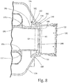
- FIG. 2B is a cross-sectional view of water extractor 46.
- Water extractor 46 includes swirler vane assembly 100, body 102, inlet 104, outlet 106 (shown in FIG. 2B ), turning vanes 108, outer duct 110, inlet 112 (shown in FIG. 2B ), outlet 114 (shown in FIG. 2B ), inner duct 116 (shown in FIG. 2B ), inlet 118 (shown in FIG. 2B ), outlet 120 (shown in FIG. 2B ), outer extractor assembly 122, first body portion 124, second body portion 126, inlet 128 (shown in FIG. 2B ), outlet 130 (shown in FIG.
- diffuser vanes 132 shown in FIG. 2B
- drain ports 134 straight ejector duct 136 (shown in FIG. 2B ), inlet 138 (shown in FIG. 2B ), outlet 140 (shown in FIG. 2B ), diffuser duct 142 (shown in FIG. 2B ), inlet 144 (shown in FIG. 2B ), and outlet 146.
- Water extractor 46 includes swirler vane assembly 100 at an inlet to water extractor 46.
- Swirler vane assembly 100 includes body 102 that forms a housing portion of swirler vane assembly 100.
- Body 102 is a straight housing that extends from inlet 104 to outlet 106 of swirler vane assembly 100.
- Turning vanes 108 are positioned in body 102 of swirler vane assembly 100 adjacent to inlet 104.
- Swirler vane assembly 100 is connected to outer duct 110.
- Outer duct 110 is a curved duct that extends from inlet 112 to outlet 114.
- Inlet 112 of outer duct 110 is connected to outlet 106 of swirler vane assembly 100.
- Inner duct 116 is positioned in outer duct 110.
- Inner duct is a curved duct that extends from inlet 118 to outlet 120.
- Outer duct 110 is connected to outer extractor assembly 122.
- Outer extractor assembly 122 includes first body portion 124 and second body portion 126 that form a housing of outer extractor assembly 122.
- Inlet 128 to outer extractor assembly 122 is positioned in first body portion 124 and outlet 130 to outer extractor assembly 122 is positioned in second body portion 126.
- Diffuser vanes 132 are positioned in first body portion 122 and second body portion 124 of outer extractor assembly 122.
- Drain ports 134 are positioned in second body portion 124 of outer extractor assembly 122.
- Straight ejector duct 136 is connected to inner duct 116 and is positioned in first body portion 124 and second body portion 126 of outer extractor assembly 122.
- Straight ejector duct 136 extends from inlet 138 to outlet 140.
- Inlet 138 of straight ejector duct 136 is connected to outlet 120 of inner duct 116.
- Diffuser duct 142 is positioned in and connected to second body portion 126 of outer extractor assembly 122.
- Diffuser duct 142 extends from inlet 144 to outlet 146.
- Diffuser duct 142 has a curved shape.
- swirler vane assembly 100 As the air flows through swirler vane assembly 100 it will flow past turning vanes 108. Turning vanes 108 will throw the water droplets that are mixed with the air outward by centrifugal forces created by turning vanes 108.
- the air will flow from swirler vane assembly 100 to outer duct 110.
- the air with the water droplets will then flow along the inner surface of outer duct 100 and through the gap between inner duct 116 and outer duct 110, as indicated by arrows B in FIG. 2B .
- the rest of the air will flow through inner duct 116, as indicated by arrow C in FIG. 2B .
- the air that flows through inner duct 116 will then flow through straight ejector duct 136, as indicated by arrow D in FIG. 2B .
- the air with the water droplets will flow into outer extractor assembly 122, as indicated by arrows E in FIG. 2B .
- the air with the water droplets will flow around diffuser vanes 132 in outer extractor assembly 122, as indicated by arrows E in FIG. 2B .
- Diffuser vanes 132 will slow the air containing the water droplets as it flows through outer extractor assembly 122, allowing the water droplets to fall to the bottom of the outer extractor assembly 122.
- the water droplets can then drain out of water extractor 46 through drain port 134 in outer extractor assembly 122.
- the air in outer extractor assembly 122 can then flow past diffuser duct 142, as indicated by arrows F in FIG. 2B .
- diffuser duct 142 There is a gap between diffuser duct 142 and second body portion 126 of outer extractor assembly 122 to allow remaining water particles in the air to be trapped in the gap and drained from outer extractor assembly 122.
- the air that flows through diffuser duct 142 will remix with the air that has flown through straight ejector duct 136, as indicated by arrows F in FIG. 2B .
- the remixed air can then exit water extractor 46 through outlet 130.
- Water extractor 46 allows water droplets to be collected from the air flowingthrough water extractor 46 and thus through environmental control system 20 (see FIGS. 1A-1B ). Reducing the amount of moisture in the air flowing through environmental control system 20 helps to dehumidify the cabin supply air to meet supply humidity and free moisture requirements while also serving to prevent damage to air cycle machine 30 of environmental control system 20. Further, reducing the amount of moisture in the air flowing through environmental control system 20 enhances performance of environmental control system 20 and provides better cabin and cockpit cooling, heating, and comfort. Water extractor 46 also minimizes the pressure drop in water extractor 46 to minimize the pressure drop in environmental control system 20 to increase the efficiency of environmental control system 20.
- FIG. 3 is a perspective view of outer duct 110 of water extractor 46.
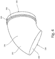
- FIG. 4 is a perspective view of inner duct 116 of water extractor 46.
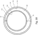
- FIG. 5A is a cross-sectional view of inner duct 116 and outer duct 110 of water extractor 46.
- FIG. 5B is a cross-sectional view of inner duct 116 and outer duct 110 of water extractor 46 taken along line 5B-5B of FIG. 5A .
- FIGS. 3-5B will be discussed together.
- Outer duct 110 (shown in FIGS. 3 and 5A-5B ) includes inlet 112 (shown in FIGS. 3 and 5A ), outlet 114 (shown in FIGS. 3 and 5A ), inner surface 150 (shown in FIGS.
- Inner duct 116 includes inlet 118 (shown in FIGS. 4 and 5A ), outlet 120(shown in FIGS. 4 and 5A ), inner surface 160 (shown in FIGS. 4 and 5A-5B ), outer surface 162 (shown in FIGS. 4 and 5A-5B ), outlet rim 164(shown in FIGS. 4 and 5A ), and flange 166(shown in FIG. 4 ). Also shown in FIGS. 5A-5B is gap 168, gap dimension G1, and gap dimension G2.
- outer duct 110 is a curved duct that extends from inlet 112 to outlet 114.
- Outer duct 110 includes inner surface 150 on an interior of outer duct 110 and outer surface 152 on an exterior of outer duct 110.
- Inlet collar 154 is positioned adjacent to inlet 112 of outer duct 110.
- Inlet collar 154 is a ring that is stepped out from outer duct 110 to form a step along inner surface 150 of outer duct 110.
- Inlet rim 156 is a raised ring that is positioned on inlet collar 154 of outer duct 110 adjacent to inlet 112. Inlet collar 154 and inlet rim 156 are used to connect outlet 106 of swirler vane assembly 100 (see FIGS.
- Outlet rim 158 is a raised ring that is positioned on outer surface 152 of outer duct 110 adjacent to outlet 114. Outlet rim 158 is used to connect inlet 128 of outer extractor assembly 122 (see FIGS. 2A-2B ) to outlet 114 of outer duct 110.
- inner duct 116 is a curved duct that extends from inlet 118 to outlet 120.
- Inner duct 116 includes inner surface 160 on an interior of inner duct 116 and outlet surface 162 on an exterior of inner duct 116.
- Outlet rim 164 is a raised ring that is positioned on outer surface 162 of inner duct 116 adjacent to outlet 120.
- Outlet rim 164 is used to connect inlet 138 of straight ejector duct 136 (see FIGS. 2A-2B ) to outlet 120 of inner duct 116.
- Flange 166 is positioned on outer surface 162 of inner duct 116 adjacent to outlet 120.
- Flange 166 is a raised surface that extends between outlet rim 164 and outlet 120 of inner duct 116.
- Flange 166 is a mistake-proofing feature.
- Inlet 138 of straight ejector duct 136 (see FIGS. 2A-2B ) has a channel cut into it to accommodate flange 166, ensuring that inner duct 116 is correctly positioned with respect to straight ejector duct 136.
- inner duct 116 is positioned in outer duct 110.
- Gap 168 is formed between outer surface 162 of inner duct 116 and inner surface 150 of outer duct 110.
- Gap 168 is positioned at inlet 118 of inner duct 116 and between inlet 112 and outlet 114 of outer duct 110.
- Gap 168 is tapered.
- Gap dimension G1 is the distance between inner duct 116 and outer duct 110 at a radially innermost section of the curve of inner duct 116 and outer duct 110.
- Gap dimension G2 is the distance between inner duct 116 and outer duct 110 at a radially outermost section of the curve of inner duct 116 and outer duct 110.
- Gap dimension G1 is greater than gap dimension G2.
- Gap 168 tapers between gap dimension G1 and gap dimension G2. The ratio of gap dimension G2 to gap dimension G1 is about 0.457.
- Gap 168 between inner duct 116 and outer duct 110 is tapered so that gap 168 is larger at gap dimension G1 than gap dimension G2 to allow more water to flow between inner duct 116 and outer duct 110 through gap 168. Due to the curvature of inner duct 116 and outer duct 110, water tends to separate from the inner wall at the radially innermost section of the curve. Making gap 168 larger at gap dimension G1 allows for better capture of the water droplets which have separated from the inner wall at the radially innermost section of the curve and enables the water to flow through gap 168 between inner duct 116 and outer duct 110. Making gap 168 smaller at gap dimension G2 still allows the water accumulation at the radially outermost section of the curve to flow through gap 168 between inner duct 116 and outer duct 110.
- Tapering gap 168 between gap dimension G1 and gap dimension G2 to account for areas of high water accumulation and low water accumulation allows water extractor 46 to efficiently extract the water droplets in the air flowing through water extractor 46.
- tapering gap 168 between gap dimension G1 and gap dimension G2 does not create an excessive pressure drop in water extractor 46. If gap 168 had a consistently large gap dimension to account for the areas of high water accumulation, there were would an unnecessary pressure drop in water extractor 46 as a large gap dimension is not needed at areas of low water accumulation. Tapering gap 168 ensures that there is not an unnecessary pressure drop in water extractor 46 while also ensuring that water extractor 46 is efficiently extracting water from the air in water extractor 46.
- FIG. 6A is a perspective view of straight ejector duct 136 of water extractor 46.
- FIG. 6B is a cross-sectional view of straight ejector duct 136 of water extractor 46.
- FIG. 7A is a perspective view of diffuser duct 142 of water extractor 46.
- FIG. 7B is a cross-sectional view of diffuser duct 142 of water extractor 46.
- FIG. 8 is a cross-sectional view of the straight ejector duct and the diffuser duct of the water extractor.
- FIGS. 6A-8 will be discussed together.
- Straight ejector duct 136 (shown in FIGS. 6A-6B and 8 ) includes inlet 138 (shown in FIGS.
- Diffuser duct 142 (shown in FIGS. 7A-7B and 8 ) includes inlet 144 (shown in FIGS. 7A-7B and 8 ), outlet 146 (shown in FIGS.
- FIGS. 7A-7B and 8 inner surface 182 (shown in FIGS. 7A-7B and 8 ), outer surface 184 (shown in FIGS. 7A-7B and 8 ), and collar 186 (shown in FIGS. 7A-7B and 8 ).
- Shown in FIGS. 6A-6B is diameter D1, diameter D2 (also shown in FIG. 8 ), length L1, and angle A1.
- Shown in FIGS. 7A-7B is diameter D3 (also shown in FIG. 8 ), diameter D4, length L2, and length L3.
- Shown in FIG. 8 is water extractor assembly 122, second body portion 126, outlet 130, gutter 188, gap 190, and gap dimension G3.
- straight ejector duct 136 extends from inlet 138 to outlet 140.
- Straight ejector duct 136 includes inner surface 170 on an interior of straight ejector duct 136 and outer surface 172 on an exterior of straight ejector duct 136.
- Straight ejector duct 136 includes inlet section 174 adjacent to inlet 138, tapering section 176, converging section 178, and outlet section 180 adjacent to outlet 140.
- Inlet section 174 is a straight duct portion extending from inlet 138.
- Tapering section 176 tapers from inlet end 174 to converging section 178.
- Converging section 178 converges from tapering section 176 to outlet section 180.
- Outlet section 180 is a straight duct portion extending from outlet 140.
- Inlet section 174 of straight ejector duct 136 had an outer diameter D1.
- Outlet section 178 of straight ejector duct 136 has an outer diameter D2.
- the ratio of outer diameter D1 to outer diameter D2 is between 1.263 and 1.2935.
- Straight ejector duct 136 has a length L1.
- the ratio of length L1 to outer diameter D2 is between 3.2378 and 3.3048.
- Converging section 178 is angled at angle A1 with respect to outlet end 180. Angle A1 is about 13.87 degrees.
- diffuser duct 142 extends from inlet 144 to outlet 146.
- Diffuser duct 142 includes inner surface 182 on an interior of diffuser duct 142 and outer surface 184 on an exterior of diffuser duct 142.
- Collar 186 is positioned on outer surface 184 of diffuser duct 142 adjacent to outlet 146 of diffuser duct 142.
- Diffuser duct 142 has a curved shape from inlet 144 to collar 186 of diffuser duct 142.
- Inner surface 182 of diffuser duct 142 has inner diameter D3 at outlet 146.
- Outer surface 184 of diffuser duct 142 has outer diameter D4 at collar 184.
- the ratio of inner diameter D3 to outer diameter D4 is between 0.9072 and 0.9290.
- Diffuser duct 142 has a length L2 from inlet 144 to outlet 146.
- the ratio of length L2 to inner diameter D3 is between 0.2686 and 0.2844.
- Collar 184 has a length L3.
- the ratio of length L3 to inner diameter D3 is between 0.0838 and 0.0973.
- diffuser duct 142 is positioned so that collar 186 abuts second body portion 126 of outer extractor assembly 122.
- Diffuser duct 142 curves upward along second body portion 126 of outer extractor assembly 122 to form gutter 188 between diffuser duct 142 and second body portion 126 of outer extractor assembly 122.
- any remaining water droplets in the air in outer extractor assembly 122 can be captured in gutter 188 between diffuser duct 142 and second body portion 126 of outer extractor assembly 122.
- outlet section 180 of straight ejector duct 136 is partially positioned in diffuser duct 142.
- outlet 140 of straight ejector duct 136 is positioned adjacent to collar 186 in diffuser duct 142.
- Gap 190 is formed between outer surface 172 of straight ejector duct 136 and inner surface 182 of diffuser duct 142.
- Gap 190 is positioned at outlet 140 of straight ejector duct 136 and collar 186 of diffuser duct 142.
- Gap dimension G3 is the distance between outer diameter D2 of straight ejector duct 136 and inner diameter D3 of diffuser duct 142.
- the ratio of outer diameter D2 to inner diameter D3 is between 0.7795 and 0.8017.
- Outer diameter D2 is about 17% to 21% smaller than inner diameter D3.
- the ratio of gap dimension G3 to outer diameter D2 and the ratio of gap dimension G3 to inner diameter D3 is between 0.1237 and 0.1415.
- Gap 190 is sized to create the correct differential pressure between the air flowing from outer extractor assembly 122 through diffuser duct 146 and the air flowing straight ejector duct 136. Creating the correct differential pressure between the air flowing from outer extractor assembly 122 through diffuser duct 146 and the air flowing straight ejector duct 136 will ensure that the air flowing through outer extractor assembly 122 will be driven through diffuser duct 146 to mix with the air in straight ejector duct 136. The air in outer extractor assembly 122 is slowed down as it flows around diffuser vanes 132 (see FIG. 2B ) so that the water in the air can be separated from the air and drained from outer extractor assembly 122.
- Gap 190 is sized to ensure that the correct differential pressure is created to drive the air flowing from outer extractor assembly 122 through diffuser duct 146 to mix with the air flowing straight ejector duct 136 and to dispel the air through outlet 130 of outer extractor assembly 122.
- water extractor 46 is designed to maximize the amount of water that can be extracted out of the air flowing through water extractor 46 and to minimize pressure drop in water extractor 46 to ensure water extractor 46 is operating efficiently.
- Gap 168 between inner duct 116 and outer duct 110 is tapered to maximize the amount of water that can be extracted out of the air flowing through water extractor 46 and to minimize pressure drop in water extractor 46.
- Gutter 188 between diffuser duct 142 and outer extractor assembly 122 is provided to capture water in outer extractor assembly 122 that otherwise would have been passed through water extractor 46.
- Outer diameter D2 of straight ejector duct 136 is sized to be 17% to 21% smaller than inner diameter D3 of diffuser duct 146 to have the correct pressure differential between straight ejector duct 136 and diffuser duct 146 to pull the air in diffuser duct 146 through to mix with the air in straight ejector duct 136.
Landscapes
- Engineering & Computer Science (AREA)
- Health & Medical Sciences (AREA)
- General Health & Medical Sciences (AREA)
- Pulmonology (AREA)
- Aviation & Aerospace Engineering (AREA)
- Mechanical Engineering (AREA)
- Chemical & Material Sciences (AREA)
- Chemical Kinetics & Catalysis (AREA)
- Apparatus For Making Beverages (AREA)
- Structures Of Non-Positive Displacement Pumps (AREA)
Claims (9)
- Wasserabscheider, der Folgendes umfasst:eine Verwirbeler-Leitschaufel-Baugruppe (100), die einen Körperabschnitt (102) mit einem Einlass (104) und einem Auslass (106) und Umlenkleitschaufeln (108), die in dem Körperabschnitt dem Einlass benachbart positioniert sind, beinhaltet;eine äußere Leitung (110) des Wasserabscheiders mit einem Einlass (112) und einem Auslass (114), wobei der Auslass der Verwirbeler-Leitschaufel-Baugruppe mit dem Einlass der äußeren Leitung verbunden ist;eine innere Leitung (116) des Wasserabscheiders mit einem Einlass (118) und einem Auslass (120), wobei die innere Leitung in der äußeren Leitung positioniert ist; undeinen Spalt (168) zwischen der inneren Leitung und der äußeren Leitung, wobei die innere Leitung und die äußere Leitung gebogene Leitungen sind, und wobei der Spalt sich zwischen einer ersten Position und einer zweiten Position verjüngt, wobei es sich bei der ersten Position um einen radial innersten Bereich einer Biegung der gebogenen Leitungen handelt, und wobei es sich bei der zweiten Position um einen radial äußersten Bereich der Biegung der gebogenen Leitungen handelt, wobei eine Spaltabmessung G1 an der ersten Position größer ist als eine Spaltabmessung G2 an der zweiten Position.
- Wasserabscheider nach Anspruch 1, wobei ein Verhältnis der Spaltabmessung G2 zu der Spaltabmessung G1 etwa 0,457 beträgt.
- Wasserabscheider nach einem der vorhergehenden Ansprüche und ferner umfassend:eine äußere Abscheiderbaugruppe (122), die einen ersten Körperabschnitt (124), einen zweiten Körperabschnitt (126), der mit dem ersten Körperabschnitt verbunden ist, einen Einlass (128) in dem ersten Körperabschnitt, einen Auslass (130) in dem zweiten Körperabschnitt und Diffusorleitschaufeln (132), die in dem ersten Körperabschnitt und dem zweiten Körperabschnitt positioniert sind, beinhaltet, wobei der Einlass der äußeren Abscheiderbaugruppe mit dem Auslass der äußeren Leitung verbunden ist;eine gerade Ausstoßleitung (136), die einen Einlass und einen Auslass beinhaltet, wobei die gerade Ausstoßleitung in der äußeren Abscheiderbaugruppe positioniert ist, und wobei der Einlass der geraden Ausstoßleitung mit dem Auslass der inneren Leitung verbunden ist; undeine Diffusorleitung (142), die einen Einlass und einen Auslass beinhaltet, wobei die Diffusorleitung in der äußeren Abscheiderbaugruppe positioniert ist, und wobei der Auslass der Diffusorleitung mit der äußeren Abscheiderbaugruppe verbunden ist.
- Wasserabscheider nach Anspruch 3, wobei:die gerade Ausstoßleitung einen äußeren Durchmesser D1 an dem Einlass und einen äußeren Durchmesser D2 an dem Auslass aufweist;die Diffusorleitung um den Auslass der geraden Ausstoßleitung positioniert ist, und wobei die Diffusorleitung einen inneren Durchmesser D3 an dem Auslass und einen äußeren Durchmesser D4 an dem Auslass aufweist; undder äußere Durchmesser D2 des Auslasses der geraden Ausstoßleitung etwa 17 % bis 21 % kleiner ist als der innere Durchmesser D3 des Auslasses der Diffusorleitung.
- Wasserabscheider nach Anspruch 4, wobei:ein Verhältnis des äußeren Durchmessers D2 zu dem inneren Durchmesser D3 zwischen 0,7795 und 0,8017 liegt;ein Verhältnis des äußeren Durchmessers D1 zu dem äußeren Durchmesser D2 zwischen 1,263 und 1,2935 liegt; undein Verhältnis des inneren Durchmessers D3 zu dem äußeren Durchmesser D4 zwischen 0,9072 und 0,9290 liegt.
- Wasserabscheider nach Anspruch 4, wobei die gerade Ausstoßleitung eine Länge L1 von dem Einlass zu dem Auslass aufweist, und wobei ein Verhältnis der Länge L1 zu dem äußeren Durchmesser D2 zwischen 3,2378 und 3,3048 liegt.
- Wasserabscheider nach Anspruch 4 und ferner umfassend:einen Spalt, der zwischen dem Auslass der Diffusorleitung und dem Auslass der geraden Ausstoßleitung gebildet wird, wobei der Spalt eine Spaltabmessung G3 zwischen einer inneren Fläche des Auslasses der Diffusorleitung und einer äußeren Fläche des Auslasses der geraden Ausstoßleitung aufweist;wobei ein Verhältnis der Spaltabmessung G3 zu dem äußeren Durchmesser D2 und ein Verhältnis der Spaltabmessung G3 zu dem inneren Durchmesser D3 zwischen 0,1237 und 0,1415 liegt.
- Wasserabscheider nach Anspruch 4, wobei die Diffusorleitung ferner Folgendes beinhaltet:einen Bund, der dem Auslass der Diffusorleitung benachbart positioniert ist;wobei der innere Durchmesser D3 des Auslasses der Diffusorleitung der innere Durchmesser des Bundes ist;wobei der äußere Durchmesser D4 des Auslasses der Diffusorleitung der äußere Durchmesser des Bundes ist; undwobei der Bund der Diffusorleitung an dem zweiten Körperabschnitt der äußeren Abscheiderbaugruppe anliegend positioniert ist, um eine Rinne zwischen der Diffusorleitung und der äußeren Abscheiderbaugruppe zu erzeugen.
- Wasserabscheider nach Anspruch 8, wobei die Diffusorleitung eine Länge L2 von dem Einlass zu dem Auslass aufweist und der Bund eine Länge L3 aufweist, wobei ein Verhältnis der Länge L2 zu dem inneren Durchmesser D3 zwischen 0,2686 und 0,2844 liegt, und wobei ein Verhältnis der Länge L3 zu dem inneren Durchmesser D3 zwischen 0,0838 und 0,0973 liegt.
Applications Claiming Priority (1)
| Application Number | Priority Date | Filing Date | Title |
|---|---|---|---|
| US15/647,505 US10668486B2 (en) | 2017-07-12 | 2017-07-12 | Water extractor |
Publications (2)
| Publication Number | Publication Date |
|---|---|
| EP3427809A1 EP3427809A1 (de) | 2019-01-16 |
| EP3427809B1 true EP3427809B1 (de) | 2020-09-02 |
Family
ID=63047123
Family Applications (1)
| Application Number | Title | Priority Date | Filing Date |
|---|---|---|---|
| EP18183275.9A Active EP3427809B1 (de) | 2017-07-12 | 2018-07-12 | Wasserabscheider |
Country Status (2)
| Country | Link |
|---|---|
| US (2) | US10668486B2 (de) |
| EP (1) | EP3427809B1 (de) |
Families Citing this family (6)
| Publication number | Priority date | Publication date | Assignee | Title |
|---|---|---|---|---|
| US10765982B2 (en) * | 2018-06-26 | 2020-09-08 | Hamilton Sundstrand Corporation | Helical water collector |
| US11767121B2 (en) * | 2020-02-07 | 2023-09-26 | Hamilton Sundstrand Corporation | Optimized environmental control system for military aircraft |
| US11261789B2 (en) * | 2020-04-15 | 2022-03-01 | Pratt & Whitney Canada Corp. | Inertial particle separator for turbine engine |
| US12139260B2 (en) * | 2021-01-29 | 2024-11-12 | Hamilton Sundstrand Corporation | Ambient air architecture with single ACM without an ambient turbine |
| US12331971B2 (en) * | 2021-09-10 | 2025-06-17 | Hamilton Sundstrand Corporation | Integrated mid-pressure water separator |
| US20240337334A1 (en) * | 2023-04-04 | 2024-10-10 | Hamilton Sundstrand Corporation | Secondary retention for adhesive bonded joints |
Family Cites Families (35)
| Publication number | Priority date | Publication date | Assignee | Title |
|---|---|---|---|---|
| GB645996A (en) | 1948-10-21 | 1950-11-15 | Napier & Son Ltd | Improvements in or relating to air intakes for gas turbines and other internal combustion engines |
| US3362155A (en) | 1965-03-29 | 1968-01-09 | Gen Electric | Axial flow separator |
| US3989489A (en) | 1975-08-04 | 1976-11-02 | Shell Oil Company | Centrifugal apparatus for gas/liquid separation |
| US3993463A (en) | 1975-08-28 | 1976-11-23 | The United States Of America As Represented By The Secretary Of The Army | Particle separator for turbine engines of aircraft |
| US4224043A (en) | 1978-04-20 | 1980-09-23 | Nfe International, Ltd. | Compact multistage particle separator |
| US4238210A (en) | 1979-04-26 | 1980-12-09 | Siegfried Bulang | Particle-removal apparatus |
| US4681610A (en) | 1986-02-13 | 1987-07-21 | United Technologies Corporation | High performance water collector |
| FR2642662B1 (fr) | 1989-02-09 | 1992-04-30 | Abg Semca | Dispositif et procede de separation des particules solides presentes dans un gaz et appareil comportant un tel dispositif |
| US6152978A (en) | 1996-02-02 | 2000-11-28 | Pall Corporation | Soot filter |
| US6056798A (en) | 1998-05-04 | 2000-05-02 | Air Equipment & Engineering,Inc. | Multi stage separator |
| WO1999059867A1 (en) | 1998-05-20 | 1999-11-25 | Alliedsignal Inc. | Coanda water extractor |
| US6302932B1 (en) | 1998-11-12 | 2001-10-16 | Honeywell International, Inc. | Combined water coalescer odor removal filter for use in water separation systems |
| US6264137B1 (en) | 2000-02-25 | 2001-07-24 | Honeywell International Inc. | Inlet vortex bustor and ice protector for auxiliary power units |
| DE10329739A1 (de) | 2003-07-02 | 2005-01-27 | Mann + Hummel Gmbh | Abscheidesystem |
| EP1680205A4 (de) | 2003-08-26 | 2007-07-04 | Hydrogenics Corp | Vorrichtung zum abtrennen von flüssigkeit von einem prozessgasstrom eines stapels elektro-chemischer zellen |
| DE102004036568A1 (de) | 2004-07-28 | 2006-02-16 | Liebherr-Aerospace Lindenberg Gmbh | Wasserabscheider für Klimaanlagen |
| US7342332B2 (en) | 2004-09-22 | 2008-03-11 | Hamilton Sundstrand Corporation | Air bearing and motor cooling |
| WO2007120161A2 (en) | 2005-06-20 | 2007-10-25 | Rolls-Royce North American Technologies, Inc. | Particle separators for gas turbine engines |
| US7470300B2 (en) | 2005-12-07 | 2008-12-30 | Honeywell International Inc. | Duct wall water extractor |
| US7770375B2 (en) | 2006-02-09 | 2010-08-10 | United Technologies Corporation | Particle collector for gas turbine engine |
| US7691185B2 (en) | 2006-12-14 | 2010-04-06 | Honeywell International Inc. | Recirculating Coanda water extractor |
| US7296395B1 (en) | 2006-12-19 | 2007-11-20 | The Boeing Company | Engine inlet air particle separator with active flow control |
| US10286407B2 (en) | 2007-11-29 | 2019-05-14 | General Electric Company | Inertial separator |
| US8177475B2 (en) | 2008-05-02 | 2012-05-15 | Honeywell International, Inc. | Contaminant-deflector labyrinth seal and method of operation |
| US8875535B2 (en) | 2009-12-02 | 2014-11-04 | Hamilton Sundstrand Corporation | Compact condenser module including a tortuous path for removing water droplets from air |
| US10184399B2 (en) | 2012-09-17 | 2019-01-22 | Honeywell International Inc. | Inlet particle separator systems and methods |
| KR101606489B1 (ko) | 2013-04-15 | 2016-03-25 | 정현욱 | 공기 순환 장치 및 필터 조립체 |
| WO2014206457A1 (en) * | 2013-06-26 | 2014-12-31 | Mann+Hummel Gmbh | Water separator for air intake systems of internal combustion engines |
| US9199248B2 (en) | 2013-10-01 | 2015-12-01 | Honeywell International Inc. | Aircraft electronic particle separation system |
| US10036319B2 (en) | 2014-10-31 | 2018-07-31 | General Electric Company | Separator assembly for a gas turbine engine |
| US20160136556A1 (en) | 2014-11-18 | 2016-05-19 | Hamilton Sundstrand Corporation | Contaminant separator for a nitrogen generation system and method of removing contaminants from an airstream |
| US10118116B2 (en) | 2015-01-07 | 2018-11-06 | Hyun-Wook Jeong | Moisture separator and air cycle system with the same |
| US9879591B2 (en) | 2015-02-20 | 2018-01-30 | Pratt & Whitney Canada Corp. | Engine intake assembly with selector valve |
| US9897093B2 (en) | 2015-03-25 | 2018-02-20 | Hamilton Sundstrand Corporation | Bearing cooling flow and energy recovery systems |
| US10322621B2 (en) | 2017-02-15 | 2019-06-18 | Hamilton Sundstrand Corporation | Inertial particle separator for air cycle machine |
-
2017
- 2017-07-12 US US15/647,505 patent/US10668486B2/en active Active
- 2017-08-17 US US15/679,772 patent/US10525485B2/en active Active
-
2018
- 2018-07-12 EP EP18183275.9A patent/EP3427809B1/de active Active
Non-Patent Citations (1)
| Title |
|---|
| None * |
Also Published As
| Publication number | Publication date |
|---|---|
| US10525485B2 (en) | 2020-01-07 |
| US20190015843A1 (en) | 2019-01-17 |
| US10668486B2 (en) | 2020-06-02 |
| EP3427809A1 (de) | 2019-01-16 |
| US20190015844A1 (en) | 2019-01-17 |
Similar Documents
| Publication | Publication Date | Title |
|---|---|---|
| EP3427809B1 (de) | Wasserabscheider | |
| EP3539635B1 (de) | Nicht-horizontaler wasserabscheider | |
| US7691185B2 (en) | Recirculating Coanda water extractor | |
| EP2479108B1 (de) | Kühlluftanlage mit einem Flüssigkeits-Luft-Wärmetauscher | |
| EP3586938B1 (de) | Spiralförmiger wasserabscheider | |
| EP3106721B1 (de) | Rückschlagventil mit mehreren klappen ohne mittelträger | |
| CN109477390A (zh) | 多工位碎屑分离系统 | |
| US12115479B2 (en) | High-pressure annular water collector with axial swirl vanes for an air cycle environmental control system | |
| EP3412354B1 (de) | Wasserabscheider mit tangentialem eintritt für flugzeug-ecs | |
| US10641294B2 (en) | Inlet tube design | |
| EP3427812B1 (de) | Wasserabscheider für umgebungskontrollsystem für ein flugzeug | |
| EP2746160B1 (de) | Ejektoranordnung | |
| EP3508424B1 (de) | Gebläse- und kompressorgehäuse für eine luftkreislaufmaschine | |
| EP2995780B1 (de) | Luftdeflektor für eine rotationsmaschine | |
| EP4268928A2 (de) | Mitteldruckwassersammler (mpwc) mit spiralförmigem strömungskanal und radialen schaufeln | |
| EP3521169B1 (de) | Dreirädrige und einfache flugzeug-klimaanlage |
Legal Events
| Date | Code | Title | Description |
|---|---|---|---|
| PUAI | Public reference made under article 153(3) epc to a published international application that has entered the european phase |
Free format text: ORIGINAL CODE: 0009012 |
|
| STAA | Information on the status of an ep patent application or granted ep patent |
Free format text: STATUS: THE APPLICATION HAS BEEN PUBLISHED |
|
| AK | Designated contracting states |
Kind code of ref document: A1 Designated state(s): AL AT BE BG CH CY CZ DE DK EE ES FI FR GB GR HR HU IE IS IT LI LT LU LV MC MK MT NL NO PL PT RO RS SE SI SK SM TR |
|
| AX | Request for extension of the european patent |
Extension state: BA ME |
|
| STAA | Information on the status of an ep patent application or granted ep patent |
Free format text: STATUS: REQUEST FOR EXAMINATION WAS MADE |
|
| 17P | Request for examination filed |
Effective date: 20190716 |
|
| RBV | Designated contracting states (corrected) |
Designated state(s): AL AT BE BG CH CY CZ DE DK EE ES FI FR GB GR HR HU IE IS IT LI LT LU LV MC MK MT NL NO PL PT RO RS SE SI SK SM TR |
|
| GRAP | Despatch of communication of intention to grant a patent |
Free format text: ORIGINAL CODE: EPIDOSNIGR1 |
|
| STAA | Information on the status of an ep patent application or granted ep patent |
Free format text: STATUS: GRANT OF PATENT IS INTENDED |
|
| INTG | Intention to grant announced |
Effective date: 20200324 |
|
| RIN1 | Information on inventor provided before grant (corrected) |
Inventor name: BARTOSZ, LANCE R Inventor name: LOKHANDWALLA, MURTUZA Inventor name: MONACCHIO, JOHN D Inventor name: SHEA, BRIAN R. |
|
| GRAS | Grant fee paid |
Free format text: ORIGINAL CODE: EPIDOSNIGR3 |
|
| GRAA | (expected) grant |
Free format text: ORIGINAL CODE: 0009210 |
|
| STAA | Information on the status of an ep patent application or granted ep patent |
Free format text: STATUS: THE PATENT HAS BEEN GRANTED |
|
| AK | Designated contracting states |
Kind code of ref document: B1 Designated state(s): AL AT BE BG CH CY CZ DE DK EE ES FI FR GB GR HR HU IE IS IT LI LT LU LV MC MK MT NL NO PL PT RO RS SE SI SK SM TR |
|
| REG | Reference to a national code |
Ref country code: GB Ref legal event code: FG4D |
|
| REG | Reference to a national code |
Ref country code: AT Ref legal event code: REF Ref document number: 1308161 Country of ref document: AT Kind code of ref document: T Effective date: 20200915 Ref country code: CH Ref legal event code: EP |
|
| REG | Reference to a national code |
Ref country code: DE Ref legal event code: R096 Ref document number: 602018007417 Country of ref document: DE |
|
| REG | Reference to a national code |
Ref country code: IE Ref legal event code: FG4D |
|
| REG | Reference to a national code |
Ref country code: LT Ref legal event code: MG4D |
|
| PG25 | Lapsed in a contracting state [announced via postgrant information from national office to epo] |
Ref country code: LT Free format text: LAPSE BECAUSE OF FAILURE TO SUBMIT A TRANSLATION OF THE DESCRIPTION OR TO PAY THE FEE WITHIN THE PRESCRIBED TIME-LIMIT Effective date: 20200902 Ref country code: HR Free format text: LAPSE BECAUSE OF FAILURE TO SUBMIT A TRANSLATION OF THE DESCRIPTION OR TO PAY THE FEE WITHIN THE PRESCRIBED TIME-LIMIT Effective date: 20200902 Ref country code: FI Free format text: LAPSE BECAUSE OF FAILURE TO SUBMIT A TRANSLATION OF THE DESCRIPTION OR TO PAY THE FEE WITHIN THE PRESCRIBED TIME-LIMIT Effective date: 20200902 Ref country code: NO Free format text: LAPSE BECAUSE OF FAILURE TO SUBMIT A TRANSLATION OF THE DESCRIPTION OR TO PAY THE FEE WITHIN THE PRESCRIBED TIME-LIMIT Effective date: 20201202 Ref country code: GR Free format text: LAPSE BECAUSE OF FAILURE TO SUBMIT A TRANSLATION OF THE DESCRIPTION OR TO PAY THE FEE WITHIN THE PRESCRIBED TIME-LIMIT Effective date: 20201203 Ref country code: SE Free format text: LAPSE BECAUSE OF FAILURE TO SUBMIT A TRANSLATION OF THE DESCRIPTION OR TO PAY THE FEE WITHIN THE PRESCRIBED TIME-LIMIT Effective date: 20200902 Ref country code: BG Free format text: LAPSE BECAUSE OF FAILURE TO SUBMIT A TRANSLATION OF THE DESCRIPTION OR TO PAY THE FEE WITHIN THE PRESCRIBED TIME-LIMIT Effective date: 20201202 |
|
| REG | Reference to a national code |
Ref country code: NL Ref legal event code: MP Effective date: 20200902 |
|
| REG | Reference to a national code |
Ref country code: AT Ref legal event code: MK05 Ref document number: 1308161 Country of ref document: AT Kind code of ref document: T Effective date: 20200902 |
|
| PG25 | Lapsed in a contracting state [announced via postgrant information from national office to epo] |
Ref country code: LV Free format text: LAPSE BECAUSE OF FAILURE TO SUBMIT A TRANSLATION OF THE DESCRIPTION OR TO PAY THE FEE WITHIN THE PRESCRIBED TIME-LIMIT Effective date: 20200902 Ref country code: PL Free format text: LAPSE BECAUSE OF FAILURE TO SUBMIT A TRANSLATION OF THE DESCRIPTION OR TO PAY THE FEE WITHIN THE PRESCRIBED TIME-LIMIT Effective date: 20200902 Ref country code: RS Free format text: LAPSE BECAUSE OF FAILURE TO SUBMIT A TRANSLATION OF THE DESCRIPTION OR TO PAY THE FEE WITHIN THE PRESCRIBED TIME-LIMIT Effective date: 20200902 |
|
| PG25 | Lapsed in a contracting state [announced via postgrant information from national office to epo] |
Ref country code: SM Free format text: LAPSE BECAUSE OF FAILURE TO SUBMIT A TRANSLATION OF THE DESCRIPTION OR TO PAY THE FEE WITHIN THE PRESCRIBED TIME-LIMIT Effective date: 20200902 Ref country code: PT Free format text: LAPSE BECAUSE OF FAILURE TO SUBMIT A TRANSLATION OF THE DESCRIPTION OR TO PAY THE FEE WITHIN THE PRESCRIBED TIME-LIMIT Effective date: 20210104 Ref country code: RO Free format text: LAPSE BECAUSE OF FAILURE TO SUBMIT A TRANSLATION OF THE DESCRIPTION OR TO PAY THE FEE WITHIN THE PRESCRIBED TIME-LIMIT Effective date: 20200902 Ref country code: CZ Free format text: LAPSE BECAUSE OF FAILURE TO SUBMIT A TRANSLATION OF THE DESCRIPTION OR TO PAY THE FEE WITHIN THE PRESCRIBED TIME-LIMIT Effective date: 20200902 Ref country code: EE Free format text: LAPSE BECAUSE OF FAILURE TO SUBMIT A TRANSLATION OF THE DESCRIPTION OR TO PAY THE FEE WITHIN THE PRESCRIBED TIME-LIMIT Effective date: 20200902 |
|
| PG25 | Lapsed in a contracting state [announced via postgrant information from national office to epo] |
Ref country code: AT Free format text: LAPSE BECAUSE OF FAILURE TO SUBMIT A TRANSLATION OF THE DESCRIPTION OR TO PAY THE FEE WITHIN THE PRESCRIBED TIME-LIMIT Effective date: 20200902 Ref country code: AL Free format text: LAPSE BECAUSE OF FAILURE TO SUBMIT A TRANSLATION OF THE DESCRIPTION OR TO PAY THE FEE WITHIN THE PRESCRIBED TIME-LIMIT Effective date: 20200902 Ref country code: ES Free format text: LAPSE BECAUSE OF FAILURE TO SUBMIT A TRANSLATION OF THE DESCRIPTION OR TO PAY THE FEE WITHIN THE PRESCRIBED TIME-LIMIT Effective date: 20200902 Ref country code: IS Free format text: LAPSE BECAUSE OF FAILURE TO SUBMIT A TRANSLATION OF THE DESCRIPTION OR TO PAY THE FEE WITHIN THE PRESCRIBED TIME-LIMIT Effective date: 20210102 |
|
| REG | Reference to a national code |
Ref country code: DE Ref legal event code: R097 Ref document number: 602018007417 Country of ref document: DE |
|
| PG25 | Lapsed in a contracting state [announced via postgrant information from national office to epo] |
Ref country code: SK Free format text: LAPSE BECAUSE OF FAILURE TO SUBMIT A TRANSLATION OF THE DESCRIPTION OR TO PAY THE FEE WITHIN THE PRESCRIBED TIME-LIMIT Effective date: 20200902 |
|
| PLBE | No opposition filed within time limit |
Free format text: ORIGINAL CODE: 0009261 |
|
| STAA | Information on the status of an ep patent application or granted ep patent |
Free format text: STATUS: NO OPPOSITION FILED WITHIN TIME LIMIT |
|
| 26N | No opposition filed |
Effective date: 20210603 |
|
| PG25 | Lapsed in a contracting state [announced via postgrant information from national office to epo] |
Ref country code: SI Free format text: LAPSE BECAUSE OF FAILURE TO SUBMIT A TRANSLATION OF THE DESCRIPTION OR TO PAY THE FEE WITHIN THE PRESCRIBED TIME-LIMIT Effective date: 20200902 Ref country code: DK Free format text: LAPSE BECAUSE OF FAILURE TO SUBMIT A TRANSLATION OF THE DESCRIPTION OR TO PAY THE FEE WITHIN THE PRESCRIBED TIME-LIMIT Effective date: 20200902 |
|
| PG25 | Lapsed in a contracting state [announced via postgrant information from national office to epo] |
Ref country code: IT Free format text: LAPSE BECAUSE OF FAILURE TO SUBMIT A TRANSLATION OF THE DESCRIPTION OR TO PAY THE FEE WITHIN THE PRESCRIBED TIME-LIMIT Effective date: 20200902 |
|
| REG | Reference to a national code |
Ref country code: CH Ref legal event code: PL |
|
| PG25 | Lapsed in a contracting state [announced via postgrant information from national office to epo] |
Ref country code: MC Free format text: LAPSE BECAUSE OF FAILURE TO SUBMIT A TRANSLATION OF THE DESCRIPTION OR TO PAY THE FEE WITHIN THE PRESCRIBED TIME-LIMIT Effective date: 20200902 |
|
| REG | Reference to a national code |
Ref country code: BE Ref legal event code: MM Effective date: 20210731 |
|
| PG25 | Lapsed in a contracting state [announced via postgrant information from national office to epo] |
Ref country code: LI Free format text: LAPSE BECAUSE OF NON-PAYMENT OF DUE FEES Effective date: 20210731 Ref country code: CH Free format text: LAPSE BECAUSE OF NON-PAYMENT OF DUE FEES Effective date: 20210731 |
|
| PG25 | Lapsed in a contracting state [announced via postgrant information from national office to epo] |
Ref country code: LU Free format text: LAPSE BECAUSE OF NON-PAYMENT OF DUE FEES Effective date: 20210712 |
|
| PG25 | Lapsed in a contracting state [announced via postgrant information from national office to epo] |
Ref country code: IE Free format text: LAPSE BECAUSE OF NON-PAYMENT OF DUE FEES Effective date: 20210712 Ref country code: BE Free format text: LAPSE BECAUSE OF NON-PAYMENT OF DUE FEES Effective date: 20210731 |
|
| P01 | Opt-out of the competence of the unified patent court (upc) registered |
Effective date: 20230522 |
|
| PG25 | Lapsed in a contracting state [announced via postgrant information from national office to epo] |
Ref country code: NL Free format text: LAPSE BECAUSE OF NON-PAYMENT OF DUE FEES Effective date: 20200923 Ref country code: CY Free format text: LAPSE BECAUSE OF FAILURE TO SUBMIT A TRANSLATION OF THE DESCRIPTION OR TO PAY THE FEE WITHIN THE PRESCRIBED TIME-LIMIT Effective date: 20200902 |
|
| PG25 | Lapsed in a contracting state [announced via postgrant information from national office to epo] |
Ref country code: HU Free format text: LAPSE BECAUSE OF FAILURE TO SUBMIT A TRANSLATION OF THE DESCRIPTION OR TO PAY THE FEE WITHIN THE PRESCRIBED TIME-LIMIT; INVALID AB INITIO Effective date: 20180712 |
|
| PG25 | Lapsed in a contracting state [announced via postgrant information from national office to epo] |
Ref country code: MK Free format text: LAPSE BECAUSE OF FAILURE TO SUBMIT A TRANSLATION OF THE DESCRIPTION OR TO PAY THE FEE WITHIN THE PRESCRIBED TIME-LIMIT Effective date: 20200902 |
|
| PG25 | Lapsed in a contracting state [announced via postgrant information from national office to epo] |
Ref country code: MT Free format text: LAPSE BECAUSE OF FAILURE TO SUBMIT A TRANSLATION OF THE DESCRIPTION OR TO PAY THE FEE WITHIN THE PRESCRIBED TIME-LIMIT Effective date: 20200902 |
|
| PGFP | Annual fee paid to national office [announced via postgrant information from national office to epo] |
Ref country code: GB Payment date: 20250619 Year of fee payment: 8 |
|
| PGFP | Annual fee paid to national office [announced via postgrant information from national office to epo] |
Ref country code: FR Payment date: 20250620 Year of fee payment: 8 |
|
| PGFP | Annual fee paid to national office [announced via postgrant information from national office to epo] |
Ref country code: DE Payment date: 20250620 Year of fee payment: 8 |
|
| PG25 | Lapsed in a contracting state [announced via postgrant information from national office to epo] |
Ref country code: TR Free format text: LAPSE BECAUSE OF FAILURE TO SUBMIT A TRANSLATION OF THE DESCRIPTION OR TO PAY THE FEE WITHIN THE PRESCRIBED TIME-LIMIT Effective date: 20200902 |