EP3427667B1 - Time calibration in pet device - Google Patents
Time calibration in pet device Download PDFInfo
- Publication number
- EP3427667B1 EP3427667B1 EP18182480.6A EP18182480A EP3427667B1 EP 3427667 B1 EP3427667 B1 EP 3427667B1 EP 18182480 A EP18182480 A EP 18182480A EP 3427667 B1 EP3427667 B1 EP 3427667B1
- Authority
- EP
- European Patent Office
- Prior art keywords
- pulse
- information
- pulse signal
- time
- energy information
- Prior art date
- Legal status (The legal status is an assumption and is not a legal conclusion. Google has not performed a legal analysis and makes no representation as to the accuracy of the status listed.)
- Active
Links
Images


Classifications
-
- A—HUMAN NECESSITIES
- A61—MEDICAL OR VETERINARY SCIENCE; HYGIENE
- A61B—DIAGNOSIS; SURGERY; IDENTIFICATION
- A61B6/00—Apparatus or devices for radiation diagnosis; Apparatus or devices for radiation diagnosis combined with radiation therapy equipment
- A61B6/02—Arrangements for diagnosis sequentially in different planes; Stereoscopic radiation diagnosis
- A61B6/03—Computed tomography [CT]
- A61B6/037—Emission tomography
-
- G—PHYSICS
- G06—COMPUTING OR CALCULATING; COUNTING
- G06T—IMAGE DATA PROCESSING OR GENERATION, IN GENERAL
- G06T12/00—Tomographic reconstruction from projections
- G06T12/10—Image preprocessing, e.g. calibration, positioning of sources or scatter correction
-
- A—HUMAN NECESSITIES
- A61—MEDICAL OR VETERINARY SCIENCE; HYGIENE
- A61B—DIAGNOSIS; SURGERY; IDENTIFICATION
- A61B6/00—Apparatus or devices for radiation diagnosis; Apparatus or devices for radiation diagnosis combined with radiation therapy equipment
- A61B6/42—Arrangements for detecting radiation specially adapted for radiation diagnosis
- A61B6/4208—Arrangements for detecting radiation specially adapted for radiation diagnosis characterised by using a particular type of detector
- A61B6/4241—Arrangements for detecting radiation specially adapted for radiation diagnosis characterised by using a particular type of detector using energy resolving detectors, e.g. photon counting
-
- A—HUMAN NECESSITIES
- A61—MEDICAL OR VETERINARY SCIENCE; HYGIENE
- A61B—DIAGNOSIS; SURGERY; IDENTIFICATION
- A61B6/00—Apparatus or devices for radiation diagnosis; Apparatus or devices for radiation diagnosis combined with radiation therapy equipment
- A61B6/58—Testing, adjusting or calibrating thereof
- A61B6/582—Calibration
-
- A—HUMAN NECESSITIES
- A61—MEDICAL OR VETERINARY SCIENCE; HYGIENE
- A61B—DIAGNOSIS; SURGERY; IDENTIFICATION
- A61B6/00—Apparatus or devices for radiation diagnosis; Apparatus or devices for radiation diagnosis combined with radiation therapy equipment
- A61B6/58—Testing, adjusting or calibrating thereof
- A61B6/582—Calibration
- A61B6/585—Calibration of detector units
-
- G—PHYSICS
- G01—MEASURING; TESTING
- G01T—MEASUREMENT OF NUCLEAR OR X-RADIATION
- G01T1/00—Measuring X-radiation, gamma radiation, corpuscular radiation, or cosmic radiation
- G01T1/29—Measurement performed on radiation beams, e.g. position or section of the beam; Measurement of spatial distribution of radiation
- G01T1/2914—Measurement of spatial distribution of radiation
- G01T1/2985—In depth localisation, e.g. using positron emitters; Tomographic imaging (longitudinal and transverse section imaging; apparatus for radiation diagnosis sequentially in different planes, steroscopic radiation diagnosis)
-
- A—HUMAN NECESSITIES
- A61—MEDICAL OR VETERINARY SCIENCE; HYGIENE
- A61B—DIAGNOSIS; SURGERY; IDENTIFICATION
- A61B6/00—Apparatus or devices for radiation diagnosis; Apparatus or devices for radiation diagnosis combined with radiation therapy equipment
- A61B6/42—Arrangements for detecting radiation specially adapted for radiation diagnosis
- A61B6/4266—Arrangements for detecting radiation specially adapted for radiation diagnosis characterised by using a plurality of detector units
-
- G—PHYSICS
- G06—COMPUTING OR CALCULATING; COUNTING
- G06T—IMAGE DATA PROCESSING OR GENERATION, IN GENERAL
- G06T2207/00—Indexing scheme for image analysis or image enhancement
- G06T2207/10—Image acquisition modality
- G06T2207/10072—Tomographic images
- G06T2207/10081—Computed x-ray tomography [CT]
-
- G—PHYSICS
- G06—COMPUTING OR CALCULATING; COUNTING
- G06T—IMAGE DATA PROCESSING OR GENERATION, IN GENERAL
- G06T2210/00—Indexing scheme for image generation or computer graphics
- G06T2210/41—Medical
-
- G—PHYSICS
- G06—COMPUTING OR CALCULATING; COUNTING
- G06T—IMAGE DATA PROCESSING OR GENERATION, IN GENERAL
- G06T2211/00—Image generation
- G06T2211/40—Computed tomography
- G06T2211/424—Iterative
Definitions
- PET Positron Emission Tomography
- a tracer containing radionuclides is injected in a subject and positrons are generated due to the decay of the tracer.
- a positron is annihilated with a negative electron within the subject, resulting in the generation of a photon pair containing two photons.
- the two photons are emitted in opposite directions.
- a PET image is reconstructed by a series of processes after an annular detector of the PET device detects the photon pair.
- SCHUG DAVID ET AL “Crystal Delay and Time Walk Correction Methods for Coincidence Resolving Time Improvements of a Digital-Silicon-Photomultiplier-Based PET/MRI Insert " discloses a time walk model, which linearly depends on the ratio of the photopeak energy to the measured energy of a single. As the photopeak energy of 511 keV was used as a reference, the walk correction was set to zero for a measured energy equal to the photopeak energy.
- This disclosure relates to an approach to calibrating time in a PET device.
- the detector may be configured to convert the photon into a pulse voltage signal or a pulse current signal.
- the corresponding pulse waveform exhibits a characteristic of linear rising and exponential attenuation over time.
- a comparator with a threshold
- a moment at which an amplitude of the pulse signal begins to be greater than the threshold may be determined as time information of the pulse signal (may also be referred to as time information of the photon), i.e. time information at which the photon is detected by the detector.
- Calibration of time information can help to improve the accuracy of the detected time information of the pulse signal, which in turn can improve the quality of reconstructed PET images generated based on the detected information.
- Higher quality PET images can have advantages for improved diagnosis and treatment of patients.
- a method of calibrating time in a Positron Emission Tomography (PET) device is defined by independent claim 1.
- a PET system is defined by independent claim 9.
- the accuracy of time information of a pulse signal detected in a PET system can affect the quality of the PET image reconstructed from that pulse signal.
- the accuracy of the time information can be improved, which can result in improved image reconstruction.
- Higher quality image reconstructions can have implications for improved diagnostic and treatment outcomes.
- a tracer containing radionuclides is injected into the subject before scanning.
- positrons may be generated due to the decay of radionuclides, and a positron is annihilated with a negative electron within the subject, thereby generating a pair of back-to-back gamma photons.
- the gamma photon pairs can be detected by scintillation crystals in a pair of detecting modules in the detector 11.
- the scintillation crystals convert the detected gamma photons into photon signals and transmit the photon signals to the photoelectric converter.
- the photoelectric converter converts the photon signals into electrical signals and transmits the electrical signals to a processing circuit.
- the processing circuit determines and outputs information of the pulse signal corresponding to the detected photon based on the electrical signal, such as time information, energy information, position information, or other types of information.
- Detection of a gamma photon by the detecting module is referred to as an event.
- Two events from the same annihilation event are referred to as a coincidence event.
- Information about a coincidence event may be used to reconstruct a PET image.
- the output of each of the detecting modules of the detector 11 may be connected to a coincidence processing circuit of the detector 11.
- the coincidence processing circuit may determine the occurrence of a coincidence event according to information of the pulse signal and transmit information of a pair of pulse signals corresponding to the coincidence event to the console device 20 for image reconstruction.
- time information and energy information of pulse signals acquired by a detecting module are relevant.
- the PET system may estimate an approximate position at which a positron is annihilated with a negative electron based on the TOF of a gamma photon pair detetcted by a pair of detecting modules.
- the approximate position may be used to reconstruct a PET image.
- accuracy of time information of a pulse signal can affect the quality of the reconstructed PET image.
- the processing circuit in each of the detecting modules of the detector 11 may include a comparator having an associated threshold.
- the comparator is configured to identify a moment at which an amplitude of a pulse signal begins to be greater than the threshold (sometimes referred to as an over-threshold moment) as time information of the pulse signal. Since the threshold is a fixed value and the difference between pulse waveforms corresponding to photons having different energies is not taken into consideration by the single threshold of the comparator, there is a timewalk between time information of photons identified by the comparator. This is because, even if photons from positron annihilation events all are gamma photons, the energy of the photons may be different, causing a difference in the time information of the corresponding pulse signals. This timewalk can affect the quality of the PET image reconstructed based on the time information of the pulse signals.
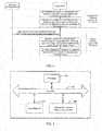
- FIG. 1B is a plot of example time (t)-voltage (V) pulse waveforms of two photons.
- V T represents a threshold of the comparator.
- the start moments of pulse waveforms corresponding to both photons are t0, but the identified time information t1 and t2 of these two photons based on the threshold V T has a timewalk. Due to the different energy of the two photons, the over-threshold moments of the pulse signals corresponding to the photons produces a shift, thereby resulting in the timewalk between time information of the photons of different energies.
- a pulse time calibration amount of the pulse signal may be obtained based on the energy information and the established correspondence.
- the original time information of the pulse signal may be calibrated with the time calibration amount of the pulse signal to enhance the accuracy of the time information of the pulse signal, thereby improving the quality of the reconstructed PET image.
- FIG. 2A is a flow chart of an example method of calibrating time in the PET device, e.g., the PET system of FIG. 1A .
- the time calibration processes described here may be performed on the PET device or on the console device.
- the process of calibrating time includes elements 201-203.
- Original time information and energy information of a pulse signal collected by a detecting module are obtained during a scanning process of the PET device (201).
- the processing circuit of the detecting module in the detector directly collects the original time information and energy information of the pulse signal.
- the console device carries out the calibration process, the detecting module in the detector may transmit the original time information and energy information of the pulse signal collected by the processing circuit to the console device.
- a scintillation crystal in each of the detecting modules detects a gamma photon, then converts the gamma photon into a photon signal and transmits the photon signal to the photoelectric converter.
- the photoelectric converter converts the photon signal into an electric signal and transmits the electric signal to the processing circuit.
- the processing circuit collects time information and energy information of a pulse signal corresponding to the detected gamma photon based on the electric signal.
- the time information before calibration such as the time information of the pulse signal collected by the processing circuit, is sometimes referred to as the original time information and the time information after calibration is sometimes referred to as the calibrated time information.
- a pulse time calibration amount corresponding to the energy information of the pulse signal is obtained according to a correspondence between pulse time calibration amount and energy information (202).
- pulse time calibration amounts can be correlated to energy information.
- the correlation can be based on characteristics of the detector.
- a pulse time calibration amount of a pulse signal is a difference between a start moment of the pulse signal and an over-threshold moment of the pulse signal.
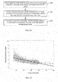
- FIG. 2B is a scatter diagram of an example of correlation between pulse time calibration amount and energy information of a detecting module of a detector.
- pulse time calibration amounts and energy information are correlated by a linear function.
- the function relationship between pulse time calibration amount and energy information is pre-analyzed for each of the detecting modules of the detector as part of the system calibration process, thereby pre-configuring a function model corresponding to the detector.
- the correspondence e.g., correlation
- the correspondence is characterized by a linear function; according to embodiments not covered by the invention, the correspondence is characterized by another functional relationship such as an exponential function, power function, or another type of function.
- Each of the function relationships may include a function model and one or more function parameters for the function model.
- the console device may acquire data of multiple pulse signals collected by each of the detecting modules. Based on the acquired data, the console device may generate function parameters corresponding to the function model of each of the detecting modules by processing the data of the pulse signals using a fitting algorithm or an iterative algorithm, based on the function model for the detector of the PET device.
- the correspondence (e.g., correlation) between pulse time calibration amount and energy information is a linear function.
- the linear function parameters a and b are calculated by a fitting algorithm.
- information of a preset number of N pulse signals is obtained by sampling the output of the detecting module during the system calibration process with a sampling module.
- N is an integer greater than 1.
- the information of each of the N pulse signals may include a combination of voltage information and time information. An example of the combination can be the pulse waveform as shown in FIG. 1B .
- the energy information E of the pulse signal may be obtained by performing a numerical integration operation for the voltage information of the pulse signal.
- the pulse time calibration amount of the pulse signal may be obtained by calculating a difference between a start moment t0 of the pulse signal and an over-threshold moment t1 of the pulse signal.
- the linear function parameters a and b of the detecting module may be obtained by performing a fitting algorithm for the pulse time calibration amount and the energy information of each of the N pulse signals.
- the number N of pulse signals may be adjusted as desired.
- the fitting algorithm may be any of a variety of fitting algorithms known to those skilled in the art, such as a least square method or another type of fitting algorithm.
- the sampling module may be integrated on the console device or may be provided independently of the console device.
- the sampling module can be a data acquisition card, an oscilloscope, or another device capable of carrying out the function of the sampling module.
- the linear function parameters a and b are calculated by an iterative algorithm.
- the console device may acquire data of N pulse signals collected by the detecting module. N is an interger greater than 1.
- the data of each pulse signal i (i is an integer from 1 to N) includes time information Ti and energy information Ei of the pulse signal i.
- 0 is assigned to the parameter a
- 0 is assigned to the parameter b.
- new values are assigned to the parameter a and the parameter b, and a new Ti ' can be obtained by formula (2).
- a new system time resolution can be determined by the new Ti' . The above iteration is repeated until the system time resolution reaches an optimum value.
- the parameters a and b when the optimum value is obtained are identified as the linear function parameters. In some examples, the optimum value of the system time resolution may be pre-set empirically.
- the correspondence may be stored in a storage medium of the console device.
- a pulse time calibration amount-energy information table for the respective modules is stored. An entry of the table is used to record energy information and a pulse time calibration amount generated by the correspondence. Because the function model and corresponding function parameters for each of the detecting modules are known for each of the detecting modules, a value of energy information can be pre-determined based on a range of the energy information. Then the corresponding pulse time calibration amount can be determined with the correspondence based on the value of the energy information. The pulse time calibration amount-energy information table for each detecting module can then be generated. To distinguish the tables for different detecting modules, the detecting modules may be numbered and each tablemay be stored in accordance with the correpsonding number. Under this storage method, a time calibration amount of a pulse signal may be determined in real time with the table.
- the console device may configure the correspondence of each of the detecting modules to the corresponding detecting module before the PET device performs a scanning process, e.g., to a logic device in the processing circuit of the detecting module.
- the logic device may include a Field Programmable Gate Array (FPGA) device, Digital Signal Processing (DSP) device, or another type of logic device.
- FPGA Field Programmable Gate Array
- DSP Digital Signal Processing
- the correspondences are stored in the corresponding detecting module.
- the original time information is calibrated with the pulse time calibration amount to obtain calibrated time information of the pulse signal for reconstructing an image (203).
- the process for obtaining calibrated time information of the pulse signal can be carried out by the console device or the PET device.
- Ti represents the original time information of the pulse signal i and Ti' represents the calibrated time information of the pulse signal i.
- a pulse time calibration amount may be obtained according to the energy information and the established correspondence.
- Calibrated time information is generated by calibrating the original time information with the pulse time calibration amount to reconstruct a PET image. This approach enables an improvement in the accuracy of time information of the pulse signal, thereby improving the quality of the reconstructed PET image.
- FIG. 3 is a flow chart of an example method of calibrating time in the PET device. This example illustrates a process of calibrating time which is finished on the PET device through interaction between the PET device and the console device.
- the process may include elements 301-307.
- the console device establishes a correspondence between pulse time calibration amount and energy information of the detecting modules during a system calibration process of the PET device (301).
- the console device stores the correspondence between pulse time calibration amount and energy information of the detecting modules in a storage medium of the console device or in a remote storage medium (302).
- the console device configures the correspondence of the detecting modules to a logic device of the detecting module before a scanning process of the PET device (303).
- the detecting module collects original time information and energy information of a pulse signal during the scanning process of the PET device (304).
- the detecting module obtains a pulse time calibration amount corresponding to the energy information of the pulse signal according to the correspondence in the logic device (305).
- the detecting module obtains calibrated time information by calibrating the original time information with the pulse time calibration amount (306).
- the detecting module transmits the calibrated time information to the console device (307).
- FIG. 4 is a flow chart of an example method of calibrating time in the PET device. This example illustrates a process of calibrating time which is finished on the console device through interaction between the PET device and the console device.
- the process may include elements 401-405.
- the console device establishes a correspondence between pulse time calibration amount and energy information of the detecting modules during a system calibration process of the PET device (401).
- the console device stores the correspondence between pulse time calibration amount and energy information of the detecting modules in a storage medium of the console device or in a remote storage medium (402).
- FIG. 3 and FIG. 4 are described with respect to FIG. 2A .
- FIG. 5 is a schematic diagram of an example hardware structure of a PET system.
- the PET system includes an internal bus 510, a non-transitory machine-readable storage medium 520, a processor 530, an external interface 540, and a PET device (not shown in FIG. 5 ) coupled to the external interface 540.
- the processor 530 may read the machine executable instructions stored in the non- transitory machine-readable storage medium 520 to perform the method of calibrating time described above.
- the processor is caused to: obtain original time information and energy information of a first pulse signal collected by a detecting module during a scanning process of the PET device, wherein a detector of the PET device comprises a plurality of detecting modules, and the original time information of the first pulse signal comprises a moment at which an amplitude of the first pulse signal begins to be greater than a threshold; determine a pulse time calibration amount corresponding to the energy information of the first pulse signal according to stored information indicative of a correspondence between the pulse time calibration amount and the energy information of each detecting module; generate calibrated time information by calibrating the original time information with the pulse time calibration amount; and reconstruct a PET image based on the generated calibrated time information.
- the processor is further caused to: establish a correspondence between the pulse time calibration amount and the energy information of each of the detecting modules during a system calibration process of the PET device; and store the correspondence between the pulse time calibration amount and the energy information of each of the detecting modules.
- the correspondence between the pulse time calibration amount and the energy information of a given detecting module is a linear function according to the invention; according to embodiments not covered by the invention, it may be one of the following function relationships: an exponential function, a power function and polynomial function.
- Each of the function relationships comprises a function model and function parameters corresponding to the function model.
- the correspondence between pulse time calibration amount and energy information of the respective detecting modules in the detector is characterized by a same function model.
- the processor when establishing the correspondence between the pulse time calibration amount and the energy information of a given detecting module, is caused to: determine a function model; obtain data of second pulse signals collected by the detecting module during the system calibration process; and determine values of one or more function parameters corresponding to the function model by calculating the data of the second pulse signals.
- the data of the second pulse signals is calculated by a fitting algorithm or an iterative algorithm.
- the processor when obtaining the data of the second pulse signals collected by the detecting module during the system calibration process, the processor is caused to: obtain information of N second pulse signals, e.g., a preset number N of second pulse signals, by sampling output of the detecting module during the system calibration process with a sampling module, wherein, N is an integer greater than 1, the information of each of the N second pulse signals comprises a combination of amplitude information and time information, and the sampling module comprises a data acquisition card or an oscilloscope; obtain energy information of each of the N second pulse signals by performing a numerical integration operation for the amplitude information of the second pulse signal; and obtain a pulse time calibration amount of each of the N second pulse signals by calculating a difference between a start moment and an over-threshold moment of the second pulse signal, wherein the over-threshold moment of the second pulse signal indicates a moment at which an amplitude of the second pulse signal begins to be greater than the threshold.
- N is an integer greater than 1
- the processor when calculating the data of the second pulse signals by the iterative algorithm, is caused to: take the one or more function parameters corresponding to the function model as iteration variables; determine new time information of each of the second pulse signals based on a value of the respective function parameters, energy information of the second pulse signal and time information of the second pulse signal obtained in a prior iteration; and when a system time resolution obtained based on the new time information of each of the second pulse signals reaches an optimum, take values of the iteration variables corresponding to the optimum as the values of the one or more function parameters when the function model is applied to the detecting module.
- the processor when storing the correspondence between the pulse time calibration amount and the energy information of the respective detecting modules, the processor is caused to perform one of: storing a function model and one or more function parameters corresponding to the function model; and storing a pulse time calibration amount-energy information table for each of the detecting modules, wherein energy information and a pulse time calibration amount generated by the correspondence are recorded in an entry of the table.
- the obtaining module is configured to obtain original time information and energy information of a first pulse signal collected by a detecting module during a scanning process of the PET device, wherein a detector of the PET device comprises a plurality of detecting modules, and the original time information of the first pulse signal comprises a moment at which an amplitude of the first pulse signal begins to be greater than a threshold.
- the determining module is configured to determine a pulse time calibration amount corresponding to the energy information of the first pulse signal according to stored information indicative of a correspondence between the pulse time calibration amount and the energy information of each detecting module.
- the generating module is configured to generate calibrated time information of the first pulse signal by calibrating the original time information with the pulse time calibration amount.
- the reconstructing module is configured to reconstruct a PET image based on the generated calibrated time information.
Landscapes
- Health & Medical Sciences (AREA)
- Life Sciences & Earth Sciences (AREA)
- Engineering & Computer Science (AREA)
- Medical Informatics (AREA)
- Physics & Mathematics (AREA)
- High Energy & Nuclear Physics (AREA)
- Molecular Biology (AREA)
- Radiology & Medical Imaging (AREA)
- Veterinary Medicine (AREA)
- Nuclear Medicine, Radiotherapy & Molecular Imaging (AREA)
- Optics & Photonics (AREA)
- Pathology (AREA)
- Biophysics (AREA)
- Biomedical Technology (AREA)
- Heart & Thoracic Surgery (AREA)
- Public Health (AREA)
- Surgery (AREA)
- Animal Behavior & Ethology (AREA)
- General Health & Medical Sciences (AREA)
- General Physics & Mathematics (AREA)
- Spectroscopy & Molecular Physics (AREA)
- Theoretical Computer Science (AREA)
- Measurement Of Radiation (AREA)
- Nuclear Medicine (AREA)
Description
- In a Positron Emission Tomography (PET) device, a tracer containing radionuclides is injected in a subject and positrons are generated due to the decay of the tracer. A positron is annihilated with a negative electron within the subject, resulting in the generation of a photon pair containing two photons. The two photons are emitted in opposite directions. A PET image is reconstructed by a series of processes after an annular detector of the PET device detects the photon pair.
- SCHUG DAVID ET AL: "Crystal Delay and Time Walk Correction Methods for Coincidence Resolving Time Improvements of a Digital-Silicon-Photomultiplier-Based PET/MRI Insert" discloses a time walk model, which linearly depends on the ratio of the photopeak energy to the measured energy of a single. As the photopeak energy of 511 keV was used as a reference, the walk correction was set to zero for a measured energy equal to the photopeak energy.
- This disclosure relates to an approach to calibrating time in a PET device. When a PET detector detects a photon, the detector may be configured to convert the photon into a pulse voltage signal or a pulse current signal. The corresponding pulse waveform exhibits a characteristic of linear rising and exponential attenuation over time. By setting a comparator with a threshold, a moment at which an amplitude of the pulse signal begins to be greater than the threshold may be determined as time information of the pulse signal (may also be referred to as time information of the photon), i.e. time information at which the photon is detected by the detector. Calibration of time information can help to improve the accuracy of the detected time information of the pulse signal, which in turn can improve the quality of reconstructed PET images generated based on the detected information. Higher quality PET images can have advantages for improved diagnosis and treatment of patients.
- In an aspect, a method of calibrating time in a Positron Emission Tomography (PET) device is defined by independent claim 1. In another aspect, a PET system is defined by independent claim 9.
- The details of one or more embodiments of the subject matter described in the present disclosure are set forth in the accompanying drawings and description below. Other features, aspects, and advantages of the subject matter will become apparent from the description, the drawings, and the claims. Features of the present disclosure are illustrated by way of example and not limited in the following figures, in which like numerals indicate like elements.
-
-
FIG. 1A is a schematic diagram of a PET system. -
FIG. 1B is a schematic diagram of time-voltage pulse waveforms of two photons. -
FIG. 2A is a flow chart of a method of calibrating time in a PET device. -
FIG. 2B is a scatter diagram between pulse time calibration amount and energy information of a detecting module of a detector. -
FIG. 3 is a flow chart of a method of calibrating time in a PET device. -
FIG.4 is a flow chart of a method of calibrating time in a PET device. -
FIG. 5 is a schematic diagram of a hardware structure of a PET system. - We describe here an approach to calibrating time information in a PET system. The accuracy of time information of a pulse signal detected in a PET system can affect the quality of the PET image reconstructed from that pulse signal. By calibrating original time information of a pulse signal with energy information of the pulse signal, the accuracy of the time information can be improved, which can result in improved image reconstruction. Higher quality image reconstructions can have implications for improved diagnostic and treatment outcomes.
-
FIG. 1A is a schematic diagram of an example PET system. The PET system includes aPET device 10 and aconsole device 20. ThePET device 10 includes adetector 11 and ascanning bed 12. Thedetector 11 may be an annular detector as shown inFIG. 1A . Theannular detector 11 includes a plurality of detecting modules. Each of the plurality of detecting modules includes sequentially connected scintillation crystals (not shown inFIG. 1A ), a photoelectric converter (not shown inFIG. 1A ) and a processing circuit (not shown inFIG. 1A ). In an example, the processing circuit includes a data acquisition (DAQ) system circuit. The DAQ system circuit includes sub-circuits that can implement different functions, such as a front-end data acquisition circuit. Thescanning bed 12 can drive a subject into thedetector 11 for scanning. - When using the PET system shown in
FIG. 1A , a tracer containing radionuclides is injected into the subject before scanning. During the scanning process, positrons may be generated due to the decay of radionuclides, and a positron is annihilated with a negative electron within the subject, thereby generating a pair of back-to-back gamma photons. The gamma photon pairs can be detected by scintillation crystals in a pair of detecting modules in thedetector 11. The scintillation crystals convert the detected gamma photons into photon signals and transmit the photon signals to the photoelectric converter. The photoelectric converter converts the photon signals into electrical signals and transmits the electrical signals to a processing circuit. The processing circuit determines and outputs information of the pulse signal corresponding to the detected photon based on the electrical signal, such as time information, energy information, position information, or other types of information. - Detection of a gamma photon by the detecting module is referred to as an event. Two events from the same annihilation event are referred to as a coincidence event. Information about a coincidence event may be used to reconstruct a PET image. In the context of the PET system of
FIG. 1A , the output of each of the detecting modules of thedetector 11 may be connected to a coincidence processing circuit of thedetector 11. The coincidence processing circuit may determine the occurrence of a coincidence event according to information of the pulse signal and transmit information of a pair of pulse signals corresponding to the coincidence event to theconsole device 20 for image reconstruction. - In determining the occurrence of a coincidence event and reconstructing images based on coincidence events, time information and energy information of pulse signals acquired by a detecting module are relevant. Taking time of flight (TOF) as an example, the PET system may estimate an approximate position at which a positron is annihilated with a negative electron based on the TOF of a gamma photon pair detetcted by a pair of detecting modules. The approximate position may be used to reconstruct a PET image. Given the role of TOF in image reconstruction, accuracy of time information of a pulse signal can affect the quality of the reconstructed PET image.
- The processing circuit in each of the detecting modules of the
detector 11 may include a comparator having an associated threshold. The comparator is configured to identify a moment at which an amplitude of a pulse signal begins to be greater than the threshold (sometimes referred to as an over-threshold moment) as time information of the pulse signal. Since the threshold is a fixed value and the difference between pulse waveforms corresponding to photons having different energies is not taken into consideration by the single threshold of the comparator, there is a timewalk between time information of photons identified by the comparator. This is because, even if photons from positron annihilation events all are gamma photons, the energy of the photons may be different, causing a difference in the time information of the corresponding pulse signals. This timewalk can affect the quality of the PET image reconstructed based on the time information of the pulse signals. -
FIG. 1B is a plot of example time (t)-voltage (V) pulse waveforms of two photons. VT represents a threshold of the comparator. The start moments of pulse waveforms corresponding to both photons are t0, but the identified time information t1 and t2 of these two photons based on the threshold VT has a timewalk. Due to the different energy of the two photons, the over-threshold moments of the pulse signals corresponding to the photons produces a shift, thereby resulting in the timewalk between time information of the photons of different energies. - We describe here an approach to establishing a correspondence between pulse time calibration amount and energy information for each of the detecting modules of the PET system based on a characteristic of the detectors of the PET device. During scanning of the PET device, when obtaining original time information and energy information of a pulse signal collected by a detecting module, a pulse time calibration amount of the pulse signal may be obtained based on the energy information and the established correspondence. The original time information of the pulse signal may be calibrated with the time calibration amount of the pulse signal to enhance the accuracy of the time information of the pulse signal, thereby improving the quality of the reconstructed PET image.
-
FIG. 2A is a flow chart of an example method of calibrating time in the PET device, e.g., the PET system ofFIG. 1A . The time calibration processes described here may be performed on the PET device or on the console device. The process of calibrating time includes elements 201-203. - Original time information and energy information of a pulse signal collected by a detecting module are obtained during a scanning process of the PET device (201). When the PET device itself carries out the calibration process, the processing circuit of the detecting module in the detector directly collects the original time information and energy information of the pulse signal. When the console device carries out the calibration process, the detecting module in the detector may transmit the original time information and energy information of the pulse signal collected by the processing circuit to the console device.
- With reference to
FIG. 1A , a scintillation crystal in each of the detecting modules detects a gamma photon, then converts the gamma photon into a photon signal and transmits the photon signal to the photoelectric converter. The photoelectric converter converts the photon signal into an electric signal and transmits the electric signal to the processing circuit. The processing circuit collects time information and energy information of a pulse signal corresponding to the detected gamma photon based on the electric signal. The time information before calibration, such as the time information of the pulse signal collected by the processing circuit, is sometimes referred to as the original time information and the time information after calibration is sometimes referred to as the calibrated time information. - A pulse time calibration amount corresponding to the energy information of the pulse signal is obtained according to a correspondence between pulse time calibration amount and energy information (202).
- During a system calibration process of the PET device, by analyzing a scatter diagram between pulse time calibration amounts and energy information of pulse signals collected by different detecting modules in the detector, pulse time calibration amounts can be correlated to energy information. The correlation can be based on characteristics of the detector. A pulse time calibration amount of a pulse signal is a difference between a start moment of the pulse signal and an over-threshold moment of the pulse signal.
- The correspondence (e.g., correlation) between pulse time calibration amounts and energy information may be characterized by different function relationships, such as linear function, exponential function, power function, polynomial function, or other types of functions. The above-described correlation of respective detecting modules in the same detector may also be characterized by a function relationship.
FIG. 2B is a scatter diagram of an example of correlation between pulse time calibration amount and energy information of a detecting module of a detector. In the example ofFIG. 2B , pulse time calibration amounts and energy information are correlated by a linear function. - The function relationship between pulse time calibration amount and energy information is pre-analyzed for each of the detecting modules of the detector as part of the system calibration process, thereby pre-configuring a function model corresponding to the detector. In particular, when the PET device performs the system calibration process, the correspondence (e.g., correlation) between pulse time calibration amount and energy information of each of the detecting modules is pre-established, e.g., by the console device. According to the invention, the correspondence is characterized by a linear function; according to embodiments not covered by the invention, the correspondence is characterized by another functional relationship such as an exponential function, power function, or another type of function. Each of the function relationships may include a function model and one or more function parameters for the function model. The function model for said linear function is y = ax + b, where a and b represent function parameters for the function model.
- In an example, to establish the correspondence (e.g., correlation) between pulse time calibration amount and energy information for each of the detecting modules, the console device may acquire data of multiple pulse signals collected by each of the detecting modules. Based on the acquired data, the console device may generate function parameters corresponding to the function model of each of the detecting modules by processing the data of the pulse signals using a fitting algorithm or an iterative algorithm, based on the function model for the detector of the PET device.
- According to the invention, the correspondence (e.g., correlation) between pulse time calibration amount and energy information is a linear function. Representing the pulse time calibration amount by deltaT and the energy information by E, the correspondence correlation between pulse time calibration amount and energy information is represented by the formula 1 as follows:

- The following decribes how to calculate the linear function parameters a and b by a fitting algorithm and an iterative algorithm, respectively, for any of the detecting modules of the detector.
- In some examples, the linear function parameters a and b are calculated by a fitting algorithm. In a fitting algorithm approach, information of a preset number of N pulse signals is obtained by sampling the output of the detecting module during the system calibration process with a sampling module. N is an integer greater than 1. When the N pulse signals are voltage signals, the information of each of the N pulse signals may include a combination of voltage information and time information. An example of the combination can be the pulse waveform as shown in
FIG. 1B . The energy information E of the pulse signal may be obtained by performing a numerical integration operation for the voltage information of the pulse signal. The pulse time calibration amount of the pulse signal may be obtained by calculating a difference between a start moment t0 of the pulse signal and an over-threshold moment t1 of the pulse signal. When the pulse time calibration amount and the energy information of each of the N pulse signals are obtained, the linear function parameters a and b of the detecting module may be obtained by performing a fitting algorithm for the pulse time calibration amount and the energy information of each of the N pulse signals. - The number N of pulse signals may be adjusted as desired. The fitting algorithm may be any of a variety of fitting algorithms known to those skilled in the art, such as a least square method or another type of fitting algorithm. The sampling module may be integrated on the console device or may be provided independently of the console device. For example, the sampling module can be a data acquisition card, an oscilloscope, or another device capable of carrying out the function of the sampling module.
- In some examples, the linear function parameters a and b are calculated by an iterative algorithm. In the iterative algorithm approach, the console device may acquire data of N pulse signals collected by the detecting module. N is an interger greater than 1. The data of each pulse signal i (i is an integer from 1 to N) includes time information Ti and energy information Ei of the pulse signal i. In some examples, the iterative operation is performed based on a linear function and a system time resolution is calculated based on new time information obtained by each iteration. In this way, during the iterative process, by taking the parameters a and b as iteration variables and the system time resolution as a target variable, an iteration formula (2) may be constructed as follows:

- Ti represents time information of the pulse signal i; and Ti' represents new time information obtained by each iteration. The system time resolution represents a full width at a top half of a Gaussian distribution curve. The Gaussian distribution curve represents a distribution of a difference between time information of a first photon detected by a first detecting module and time information of a second photon detected by a second detecting module, where the first photon and the second photon are from a same positron annihilation event. During each iteration, the new time information generated by each iteration is applied to determine the system time resolution.
- At the start of the iteration (Ti' = Ti.), 0 is assigned to the parameter a, and 0 is assigned to the parameter b. During each subsequent iteration, new values are assigned to the parameter a and the parameter b, and a new Ti' can be obtained by formula (2). A new system time resolution can be determined by the new Ti'. The above iteration is repeated until the system time resolution reaches an optimum value. The parameters a and b when the optimum value is obtained are identified as the linear function parameters. In some examples, the optimum value of the system time resolution may be pre-set empirically.
- When the correspondence between pulse time calibration amount and energy information is established for the detecting module by the console device, the correspondence may be stored in a storage medium of the console device.
- In some examples, the function model and the function parameters for the detecting modules are stored. Because the each of the detecting modules of the same detector adopts the same function model, the pre-configured function model and the function parameters for the respective detecting modules may be stored. To distinguish the function parameters for different detecting modules, the detecting modules may be numbered and each set of function parameters may be stored in accordance with the corresponding number. Under this storage method, a time calibration amount of a pulse signal may be calculated in real time based on the function model and the corresponding function parameters. Taking the linear function a according to the invention as an example, the function model deltaT = a x E + b and the function parameters a, b for the each detecting modules may be stored in the console device.
- In some examples, a pulse time calibration amount-energy information table for the respective modules is stored. An entry of the table is used to record energy information and a pulse time calibration amount generated by the correspondence. Because the function model and corresponding function parameters for each of the detecting modules are known for each of the detecting modules, a value of energy information can be pre-determined based on a range of the energy information. Then the corresponding pulse time calibration amount can be determined with the correspondence based on the value of the energy information. The pulse time calibration amount-energy information table for each detecting module can then be generated. To distinguish the tables for different detecting modules, the detecting modules may be numbered and each tablemay be stored in accordance with the correpsonding number. Under this storage method, a time calibration amount of a pulse signal may be determined in real time with the table.
- Referring again to
FIG. 2A , when the console device performs the process for correlating pulse time calibration amount and energy information (202), when receiving the original time information and energy information transmitted by the detecting module, the console device may read the correspondence of the detecting module from the storage medium and obtain the pulse time calibration amount corresponding to energy information according to the correspondence. - When the PET device performs the process for correlating pulse time calibration amount and energy information, the console device may configure the correspondence of each of the detecting modules to the corresponding detecting module before the PET device performs a scanning process, e.g., to a logic device in the processing circuit of the detecting module. The logic device may include a Field Programmable Gate Array (FPGA) device, Digital Signal Processing (DSP) device, or another type of logic device. The correspondences are stored in the corresponding detecting module. When the original time information and energy information of the pulse signal is collected by the detecting module of the PET device, the pulse time calibration amount corresponding to the energy information is obtained according to the stored correspondence.
- The original time information is calibrated with the pulse time calibration amount to obtain calibrated time information of the pulse signal for reconstructing an image (203). The process for obtaining calibrated time information of the pulse signal can be carried out by the console device or the PET device. After obtaining the pulse time calibration amount, the original time information may be calibrated with the following formula (3)

- Ti represents the original time information of the pulse signal i and Ti' represents the calibrated time information of the pulse signal i.
- During the scanning process of the PET device, after obtaining the original time information and the energy information of the pulse signal collected by the detecting module, a pulse time calibration amount may be obtained according to the energy information and the established correspondence. Calibrated time information is generated by calibrating the original time information with the pulse time calibration amount to reconstruct a PET image. This approach enables an improvement in the accuracy of time information of the pulse signal, thereby improving the quality of the reconstructed PET image.
-
FIG. 3 is a flow chart of an example method of calibrating time in the PET device. This example illustrates a process of calibrating time which is finished on the PET device through interaction between the PET device and the console device. The process may include elements 301-307. - The console device establishes a correspondence between pulse time calibration amount and energy information of the detecting modules during a system calibration process of the PET device (301). The console device stores the correspondence between pulse time calibration amount and energy information of the detecting modules in a storage medium of the console device or in a remote storage medium (302). The console device configures the correspondence of the detecting modules to a logic device of the detecting module before a scanning process of the PET device (303).
- The detecting module collects original time information and energy information of a pulse signal during the scanning process of the PET device (304). The detecting module obtains a pulse time calibration amount corresponding to the energy information of the pulse signal according to the correspondence in the logic device (305). The detecting module obtains calibrated time information by calibrating the original time information with the pulse time calibration amount (306). The detecting module transmits the calibrated time information to the console device (307).
-
FIG. 4 is a flow chart of an example method of calibrating time in the PET device. This example illustrates a process of calibrating time which is finished on the console device through interaction between the PET device and the console device. The process may include elements 401-405. - The console device establishes a correspondence between pulse time calibration amount and energy information of the detecting modules during a system calibration process of the PET device (401). The console device stores the correspondence between pulse time calibration amount and energy information of the detecting modules in a storage medium of the console device or in a remote storage medium (402).
- The console device receives original time information and energy information of a pulse signal collected by the detecting module during the scanning process of the PET device (403). The console device obtains a pulse time calibration amount corresponding to the energy information of the pulse signal by searching a correspondence of the detecting module stored in the storage medium (404). The console device obtains calibrated time information by calibrating the original time information with the pulse time calibration amount to reconstruct a PET image (405).
- The processes depicted in
FIG. 3 andFIG. 4 are described with respect toFIG. 2A . - The order of execution of the respective steps in the above-described flowcharts shown in
FIGs. 2A ,3 and4 are not limited to the order in the respective flowcharts. In addition, the description of the respective steps may be implemented in the form of software, hardware, or a combination thereof. For example, those skilled in the art may implement it as a software code, including machine executable instructions to enable logical function corresponding to the respective steps. When it is implemented in the form of software, the machine executable may be stored in a memory and executed by a processor in the device. -
FIG. 5 is a schematic diagram of an example hardware structure of a PET system. The PET system includes an internal bus 510, a non-transitory machine-readable storage medium 520, aprocessor 530, an external interface 540, and a PET device (not shown inFIG. 5 ) coupled to the external interface 540. Theprocessor 530 may read the machine executable instructions stored in the non- transitory machine-readable storage medium 520 to perform the method of calibrating time described above. - In some examples, by invoking machine executable instructions stored in the non-transitory machine readable storage medium, the processor is caused to: obtain original time information and energy information of a first pulse signal collected by a detecting module during a scanning process of the PET device, wherein a detector of the PET device comprises a plurality of detecting modules, and the original time information of the first pulse signal comprises a moment at which an amplitude of the first pulse signal begins to be greater than a threshold; determine a pulse time calibration amount corresponding to the energy information of the first pulse signal according to stored information indicative of a correspondence between the pulse time calibration amount and the energy information of each detecting module; generate calibrated time information by calibrating the original time information with the pulse time calibration amount; and reconstruct a PET image based on the generated calibrated time information.
- In an example, the processor is further caused to: establish a correspondence between the pulse time calibration amount and the energy information of each of the detecting modules during a system calibration process of the PET device; and store the correspondence between the pulse time calibration amount and the energy information of each of the detecting modules.
- The correspondence between the pulse time calibration amount and the energy information of a given detecting module is a linear function according to the invention; according to embodiments not covered by the invention, it may be one of the following function relationships: an exponential function, a power function and polynomial function. Each of the function relationships comprises a function model and function parameters corresponding to the function model. The correspondence between pulse time calibration amount and energy information of the respective detecting modules in the detector is characterized by a same function model.
- In an example, when establishing the correspondence between the pulse time calibration amount and the energy information of a given detecting module, the processor is caused to: determine a function model; obtain data of second pulse signals collected by the detecting module during the system calibration process; and determine values of one or more function parameters corresponding to the function model by calculating the data of the second pulse signals. The data of the second pulse signals is calculated by a fitting algorithm or an iterative algorithm.
- In an example, when obtaining the data of the second pulse signals collected by the detecting module during the system calibration process, the processor is caused to: obtain information of N second pulse signals, e.g., a preset number N of second pulse signals, by sampling output of the detecting module during the system calibration process with a sampling module, wherein, N is an integer greater than 1, the information of each of the N second pulse signals comprises a combination of amplitude information and time information, and the sampling module comprises a data acquisition card or an oscilloscope; obtain energy information of each of the N second pulse signals by performing a numerical integration operation for the amplitude information of the second pulse signal; and obtain a pulse time calibration amount of each of the N second pulse signals by calculating a difference between a start moment and an over-threshold moment of the second pulse signal, wherein the over-threshold moment of the second pulse signal indicates a moment at which an amplitude of the second pulse signal begins to be greater than the threshold.
- In an example, when calculating the data of the second pulse signals by the iterative algorithm, the processor is caused to: take the one or more function parameters corresponding to the function model as iteration variables; determine new time information of each of the second pulse signals based on a value of the respective function parameters, energy information of the second pulse signal and time information of the second pulse signal obtained in a prior iteration; and when a system time resolution obtained based on the new time information of each of the second pulse signals reaches an optimum, take values of the iteration variables corresponding to the optimum as the values of the one or more function parameters when the function model is applied to the detecting module.
- In an example, when storing the correspondence between the pulse time calibration amount and the energy information of the respective detecting modules, the processor is caused to perform one of: storing a function model and one or more function parameters corresponding to the function model; and storing a pulse time calibration amount-energy information table for each of the detecting modules, wherein energy information and a pulse time calibration amount generated by the correspondence are recorded in an entry of the table.
- In examples of the present disclosure, an apparatus of calibrating time in a PET device is provided. The apparatus includes an obtaining module, a determining module, a generating module and a reconstructing module.
- The obtaining module is configured to obtain original time information and energy information of a first pulse signal collected by a detecting module during a scanning process of the PET device, wherein a detector of the PET device comprises a plurality of detecting modules, and the original time information of the first pulse signal comprises a moment at which an amplitude of the first pulse signal begins to be greater than a threshold.
- The determining module is configured to determine a pulse time calibration amount corresponding to the energy information of the first pulse signal according to stored information indicative of a correspondence between the pulse time calibration amount and the energy information of each detecting module.
- The generating module is configured to generate calibrated time information of the first pulse signal by calibrating the original time information with the pulse time calibration amount.
- The reconstructing module is configured to reconstruct a PET image based on the generated calibrated time information.
- For simplicity and illustrative purposes, the present disclosure is described by referring mainly to examples thereof. In the above descriptions, numerous specific details are set forth in order to provide a thorough understanding of the present disclosure. It will be readily apparent however, that the present disclosure may be practiced without limitation to these specific details. In other instances, some methods and structures have not been described in detail so as not to unnecessarily obscure the present disclosure. As used herein, the terms "a" and "an" are intended to denote at least one of a particular element, the term "includes" means includes but not limited to, the term "including" means including but not limited to, and the term "based on" means based at least in part on.
- The above description provides examples and is not intended to limit the present disclosure in any form. Although the present disclosure is disclosed by the above examples, the examples are not intended to limit the present disclosure. Those skilled in the art, without departing from the scope of the technical scheme of the present disclosure, may make a plurality of changes and modifications of the technical scheme of the present disclosure by the method and technical content disclosed above.
Claims (12)
- A method of calibrating time in a Positron Emission Tomography (PET) device, the method comprising:obtaining (201) original time information and energy information of a first pulse signal collected by a detecting module during a scanning process of the PET device, wherein a detector of the PET device comprises a plurality of detecting modules, the original time information of the first pulse signal comprises a moment at which an amplitude of the first pulse signal begins to be greater than a threshold, and the energy information of the first pulse signal is determined by performing a numerical integration for amplitude information of the first pulse signal;determining (202) a pulse time calibration amount corresponding to the energy information of the first pulse signal according to stored information indicative of a correspondence between the pulse time calibration amount and the energy information of each detecting module, wherein the correspondence of each detecting module is a linear function, the linear function i being:
 wherein deltaT represents the pulse time calibration amount of the first pulse signal, E represents the energy information of the first pulse signal, a and b represents function parameters of the linear function;generating calibrated time information of the first pulse signal by calibrating the original time information with the pulse time calibration amount; andreconstructing a PET image based on the generated calibrated time information.
 - The method of claim 1, comprising:establishing a correspondence between the pulse time calibration amount and the energy information of each of the detecting modules during a system calibration process of the PET device; andstoring the correspondence between the pulse time calibration amount and the energy information of each of the detecting modules.
- The method of claim 1, wherein establishing the correspondence between the pulse time calibration amount and the energy information of a given detecting module comprises:obtaining data of second pulse signals collected by the detecting module during the system calibration process; anddetermining values of the function parameters by calculating the data of the second pulse signals.
- The method of claim 3, wherein obtaining the data of the second pulse signals collected by the detecting module during the system calibration process comprises:obtaining information of N second pulse signals by sampling output of the detecting module during the system calibration process with a sampling module, wherein N is an integer greater than 1, and wherein the information of each of the N second pulse signals comprises a combination of amplitude information and time information, and the sampling module comprises a data acquisition card or an oscilloscope;obtaining energy information of each of the N second pulse signals by performing a numerical integration operation for the amplitude information of the second pulse signal; andobtaining a pulse time calibration amount of each of the N second pulse signals by calculating a difference between a start moment and an over-threshold moment of the second pulse signal, wherein the over-threshold moment of the second pulse signal indicates a moment at which an amplitude of the second pulse signal begins to be greater than the threshold.
- The method of claim 3, wherein calculating the data of the second pulse signals comprises:
calculating the data of the second pulse signals by a fitting algorithm. - The method of claim 3, wherein calculating the data of the second pulse signals comprises:
calculating the data of the second pulse signals by an iterative algorithm. - The method of claim 6, wherein calculating the data of the second pulse signals by the iterative algorithm comprises:taking the function parameters as iteration variables;determining new time information of each of the second pulse signals based on a value of the respective function parameters, energy information of the second pulse signal and time information of the second pulse signal obtained in a prior iteration; andwhen a system time resolution obtained based on the new time information of each of the second pulse signals reaches an optimum, taking values of the iteration variables corresponding to the optimum as the values of the one or more function parameters when the function model is applied to the detecting module.
- The method of claim 2, wherein storing the correspondence between the pulse time calibration amount and the energy information of the respective detecting modules comprises one of:storing the linear function and the function parameters corresponding to the linear function; andstoring a pulse time calibration amount-energy information table for each of the detecting modules, wherein record energy information and a pulse time calibration amount generated by the correspondence are recorded in an entry of the table.
- A PET system comprising:a PET device (10);one or more processors (530); anda non-transitory machine readable storage medium (520);wherein the one or more processors (530) are configured to invoke machine executable instructions stored in the non-transitory machine readable storage medium (520) to:obtain original time information and energy information of a first pulse signal collected by a detecting module during a scanning process of the PET device, wherein a detector of the PET device comprises a plurality of detecting modules, the original time information of the first pulse signal comprises a moment at which an amplitude of the first pulse signal begins to be greater than a threshold, and the energy information of the first pulse signal is determined by performing a numerical integration for amplitude information of the first pulse signal;determine a pulse time calibration amount corresponding to the energy information of the first pulse signal according to stored information indicative of a correspondence between the pulse time calibration amount and the energy information of each detecting module, wherein the correspondence of each detecting module is a linear function, the linear function i being:
 wherein deltaT represents the pulse time calibration amount of the first pulse signal, E represents the energy information of the first pulse signal, a and b represents function parameters of the linear function;generate calibrated time information of the first pulse signal by calibrating the original time information with the pulse time calibration amount; andreconstruct a PET image based on the generated calibrated time information.
 - The system of claim 9, wherein establishing the correspondence between the pulse time calibration amount and the energy information of a given detecting module comprises:obtaining data of second pulse signals collected by the detecting module during the system calibration process; anddetermining values of the function parameters by calculating the data of the second pulse signals.
- The system of claim 10, wherein obtaining the data of the second pulse signals collected by the detecting module during the system calibration process comprises:obtaining information of N second pulse signals by sampling output of the detecting module during the system calibration process with a sampling module, wherein, N is an integer greater than 1, the information of each of the N second pulse signals comprises a combination of amplitude information and time information, and the sampling module comprises a data acquisition card or an oscilloscope;obtaining energy information of each of the N second pulse signals by performing a numerical integration operation for the amplitude information of the second pulse signal; andobtaining a pulse time calibration amount of each of the N second pulse signals by calculating a difference between a start moment and an over-threshold moment of the second pulse signal, wherein the over-threshold moment of the second pulse signal indicates a moment at which an amplitude of the second pulse signal begins to be greater than the threshold.
- An apparatus of calibrating time in a PET device, the apparatus comprising:an obtaining module configured to obtain original time information and energy information of a first pulse signal collected by a detecting module during a scanning process of the PET device, wherein a detector of the PET device comprises a plurality of detecting modules, the original time information of the first pulse signal comprises a moment at which an amplitude of the first pulse signal begins to be greater than a threshold, and the energy information of the first pulse signal is determined by performing a numerical integration for amplitude information of the first pulse signal;a determining module configured to determine a pulse time calibration amount corresponding to the energy information of the first pulse signal according to stored information indicative of a correspondence between the pulse time calibration amount and the energy information of each detecting module, wherein the correspondence of each detecting module is a linear function, the linear function i being:
 wherein deltaT represents the pulse time calibration amount of the first pulse signal, E represents the energy information of the first pulse signal, a and b represents function parameters of the linear function;a generating module configured to generate calibrated time information of the first pulse signal by calibrating the original time information with the pulse time calibration amount; anda reconstructing module configured to reconstruct a PET image based on the generated calibrated time information.
Applications Claiming Priority (1)
| Application Number | Priority Date | Filing Date | Title |
|---|---|---|---|
| CN201710556109.7A CN107260197B (en) | 2017-07-10 | 2017-07-10 | Time correction method, device and equipment |
Publications (2)
| Publication Number | Publication Date |
|---|---|
| EP3427667A1 EP3427667A1 (en) | 2019-01-16 |
| EP3427667B1 true EP3427667B1 (en) | 2020-10-07 |
Family
ID=60073311
Family Applications (1)
| Application Number | Title | Priority Date | Filing Date |
|---|---|---|---|
| EP18182480.6A Active EP3427667B1 (en) | 2017-07-10 | 2018-07-09 | Time calibration in pet device |
Country Status (3)
| Country | Link |
|---|---|
| US (1) | US10755452B2 (en) |
| EP (1) | EP3427667B1 (en) |
| CN (1) | CN107260197B (en) |
Families Citing this family (9)
| Publication number | Priority date | Publication date | Assignee | Title |
|---|---|---|---|---|
| CN110161552B (en) * | 2019-04-28 | 2021-03-05 | 东软医疗系统股份有限公司 | Data processing method, device and equipment for detector |
| CN110327063B (en) * | 2019-06-10 | 2023-05-12 | 沈阳智核医疗科技有限公司 | Energy correction method, device, console device and PET system |
| CN111012372B (en) * | 2019-12-20 | 2023-05-09 | 沈阳智核医疗科技有限公司 | Method, device, medium and positron emission tomography scanner for determining flight time |
| CN111025369B (en) * | 2019-12-23 | 2021-10-26 | 赛诺联合医疗科技(北京)有限公司 | Method for correcting timing precision by using energy information in PET system |
| CN111736207B (en) * | 2020-05-28 | 2022-06-07 | 广东明峰医疗科技有限公司 | PET time calibration method |
| CN113520435B (en) * | 2021-06-24 | 2024-05-24 | 上海联影微电子科技有限公司 | Time correction method, device, computer equipment and storage medium |
| US11841472B2 (en) | 2021-04-16 | 2023-12-12 | Shanghai United Imaging Microelectronics Technology Co., Ltd. | Devices, systems, and methods for time correction |
| CN115951392B (en) * | 2022-12-17 | 2025-10-24 | 苏州瑞派宁科技有限公司 | Energy correction method, device, electronic device, detection device and storage medium |
| CN116068607A (en) * | 2023-01-18 | 2023-05-05 | 江苏赛诺格兰医疗科技有限公司 | Method, system, device and medium for correcting timed walk based on energy information |
Family Cites Families (20)
| Publication number | Priority date | Publication date | Assignee | Title |
|---|---|---|---|---|
| CN101080653B (en) * | 2004-12-17 | 2012-02-29 | 皇家飞利浦电子股份有限公司 | X ray photographic equipment, method and computerized tomography |
| US7787592B2 (en) * | 2006-02-23 | 2010-08-31 | Shimadzu Corporation | Radiographic apparatus and radiation detection signal processing method |
| WO2008040384A1 (en) * | 2006-10-04 | 2008-04-10 | Cern - European Organization For Nuclear Research | Readout circuit for use in a combined pet-ct apparatus |
| US8269177B2 (en) * | 2010-02-28 | 2012-09-18 | General Electric Company | Multiplexing readout scheme for a gamma ray detector |
| WO2012044311A1 (en) * | 2010-09-30 | 2012-04-05 | Analogic Corporation | Non-linear data acquisition |
| CN103961126B (en) | 2013-02-05 | 2016-07-06 | 苏州瑞派宁科技有限公司 | A kind of threshold correction method of multi thresholds sampling digitizing device |
| CN103969675B (en) | 2013-02-05 | 2017-08-04 | 苏州瑞派宁科技有限公司 | Baseline correction method and system for digitized scintillation pulses |
| US8796637B1 (en) * | 2013-05-24 | 2014-08-05 | Kabushiki Kaisha Toshiba | Timing calibration for time-of-flight (TOF) PET using positron-emitting isotopes and annihilation targets |
| CN103488247A (en) | 2013-09-17 | 2014-01-01 | 沈阳东软医疗系统有限公司 | Clock calibration method, device and system |
| US10527740B2 (en) * | 2014-04-03 | 2020-01-07 | Siemens Medical Solutions Usa, Inc. | Silicon photomultiplier based TOF-PET detector |
| US9693751B2 (en) * | 2014-04-18 | 2017-07-04 | Siemens Medical Solutions Usa, Inc. | Patient based detector crystal quality control for time of flight acquisition |
| US10022097B2 (en) * | 2014-06-16 | 2018-07-17 | University Of Southern California | Direct patlak estimation from list-mode PET data |
| CN105204060B (en) * | 2014-06-19 | 2018-06-08 | 苏州瑞派宁科技有限公司 | Radiation detection, measurement, identification, the timing means of imaging system and method |
| EP3198307B1 (en) | 2014-09-23 | 2020-11-11 | Koninklijke Philips N.V. | Time of flight calibration in digital positron emission tomography |
| CN104644204A (en) * | 2015-02-09 | 2015-05-27 | 中国船舶重工集团公司第七一九研究所 | Time correcting method and system for digital PET (positron emission tomography) |
| US10527741B2 (en) * | 2015-04-07 | 2020-01-07 | Siemens Medical Solutions Usa, Inc. | Setup of SIPM based PET detector using LSO background radiation |
| CN105030263B (en) * | 2015-07-22 | 2018-06-12 | 湖北锐世数字医学影像科技有限公司 | The energy back bearing calibration of number PET a kind of and system |
| CN105193442B (en) | 2015-09-17 | 2018-12-25 | 沈阳东软医疗系统有限公司 | A kind of determination method and apparatus of PET scan time |
| CN106725560B (en) * | 2015-11-19 | 2021-01-12 | 上海联影医疗科技股份有限公司 | Performance detection method of optical sensor and medical imaging equipment |
| CN105737853B (en) | 2016-02-04 | 2018-11-23 | 中国科学院电子学研究所 | A kind of drift calibration method of robot inertial navigation system |
-
2017
- 2017-07-10 CN CN201710556109.7A patent/CN107260197B/en active Active
-
2018
- 2018-06-26 US US16/019,107 patent/US10755452B2/en active Active
- 2018-07-09 EP EP18182480.6A patent/EP3427667B1/en active Active
Non-Patent Citations (1)
| Title |
|---|
| None * |
Also Published As
| Publication number | Publication date |
|---|---|
| US20190012812A1 (en) | 2019-01-10 |
| EP3427667A1 (en) | 2019-01-16 |
| CN107260197A (en) | 2017-10-20 |
| US10755452B2 (en) | 2020-08-25 |
| CN107260197B (en) | 2020-11-10 |
Similar Documents
| Publication | Publication Date | Title |
|---|---|---|
| EP3427667A1 (en) | Time calibration in pet device | |
| AU2009230876B2 (en) | Radiation imaging method with individual signal resolution | |
| US10101474B2 (en) | Pixel based dead time correction | |
| CN110327067B (en) | Image reconstruction method, device, terminal equipment and PET system | |
| KR102266123B1 (en) | X-ray imaging based on image data from a photon-counting multi bin x-ray detector | |
| US8089037B2 (en) | Real-time gain compensation for photo detectors based on energy peak detection | |
| CN103221841B (en) | PET calibration with varying concurrency window | |
| US8610081B2 (en) | Systems and methods for generating control signals in radiation detector systems | |
| EP3033637B1 (en) | A hybrid method based on simulation and experimental data to normalize pet data | |
| EP3796048B1 (en) | Method and device for sampling pulse signal, and computer program medium | |
| EP2748594B1 (en) | Radiographic apparatus for detecting photons with offset correction | |
| CN106716179A (en) | Time of flight calibration in digital positron emission tomography | |
| CN110415311B (en) | PET image reconstruction method, system, readable storage medium and device | |
| JP2020064045A (en) | Medical image processing apparatus, method and program | |
| CN113520435B (en) | Time correction method, device, computer equipment and storage medium | |
| CN113100796A (en) | PET system correction method, apparatus, electronic apparatus, and storage medium | |
| JP2013234995A (en) | Random coincidence count estimating method and random coincidence count estimating device | |
| US20110142367A1 (en) | Methods and systems for correcting image scatter | |
| US11096634B2 (en) | Scatter correction based on energy response | |
| CN110327063B (en) | Energy correction method, device, console device and PET system | |
| CN108703769B (en) | Method, device and system for correcting TOF data and computer-readable storage medium | |
| CN112022189A (en) | Image reconstruction method, device and equipment and PET system | |
| CN111685788A (en) | Method for improving signal-to-noise ratio of PET | |
| CN115462818B (en) | A method for real-time calibration of PET system based on real-time clinical scan data | |
| US20260069231A1 (en) | Determination of respiratory waveform from singles rates |
Legal Events
| Date | Code | Title | Description |
|---|---|---|---|
| PUAI | Public reference made under article 153(3) epc to a published international application that has entered the european phase |
Free format text: ORIGINAL CODE: 0009012 |
|
| STAA | Information on the status of an ep patent application or granted ep patent |
Free format text: STATUS: REQUEST FOR EXAMINATION WAS MADE |
|
| 17P | Request for examination filed |
Effective date: 20180709 |
|
| AK | Designated contracting states |
Kind code of ref document: A1 Designated state(s): AL AT BE BG CH CY CZ DE DK EE ES FI FR GB GR HR HU IE IS IT LI LT LU LV MC MK MT NL NO PL PT RO RS SE SI SK SM TR |
|
| AX | Request for extension of the european patent |
Extension state: BA ME |
|
| RBV | Designated contracting states (corrected) |
Designated state(s): AL AT BE BG CH CY CZ DE DK EE ES FI FR GB GR HR HU IE IS IT LI LT LU LV MC MK MT NL NO PL PT RO RS SE SI SK SM TR |
|
| GRAP | Despatch of communication of intention to grant a patent |
Free format text: ORIGINAL CODE: EPIDOSNIGR1 |
|
| STAA | Information on the status of an ep patent application or granted ep patent |
Free format text: STATUS: GRANT OF PATENT IS INTENDED |
|
| RIC1 | Information provided on ipc code assigned before grant |
Ipc: G01T 1/20 20060101ALI20200513BHEP Ipc: G01T 1/172 20060101ALI20200513BHEP Ipc: G01T 1/36 20060101ALI20200513BHEP Ipc: A61B 6/03 20060101AFI20200513BHEP Ipc: A61B 6/00 20060101ALI20200513BHEP Ipc: G01T 1/29 20060101ALI20200513BHEP Ipc: G01T 7/00 20060101ALI20200513BHEP |
|
| RAP1 | Party data changed (applicant data changed or rights of an application transferred) |
Owner name: SHENYANG NEUSOFT MEDICAL SYSTEMS CO., LTD. |
|
| INTG | Intention to grant announced |
Effective date: 20200609 |
|
| GRAS | Grant fee paid |
Free format text: ORIGINAL CODE: EPIDOSNIGR3 |
|
| GRAA | (expected) grant |
Free format text: ORIGINAL CODE: 0009210 |
|
| STAA | Information on the status of an ep patent application or granted ep patent |
Free format text: STATUS: THE PATENT HAS BEEN GRANTED |
|
| RAP1 | Party data changed (applicant data changed or rights of an application transferred) |
Owner name: NEUSOFT MEDICAL SYSTEMS CO., LTD. |
|
| AK | Designated contracting states |
Kind code of ref document: B1 Designated state(s): AL AT BE BG CH CY CZ DE DK EE ES FI FR GB GR HR HU IE IS IT LI LT LU LV MC MK MT NL NO PL PT RO RS SE SI SK SM TR |
|
| REG | Reference to a national code |
Ref country code: GB Ref legal event code: FG4D |
|
| REG | Reference to a national code |
Ref country code: AT Ref legal event code: REF Ref document number: 1320308 Country of ref document: AT Kind code of ref document: T Effective date: 20201015 Ref country code: CH Ref legal event code: EP |
|
| REG | Reference to a national code |
Ref country code: IE Ref legal event code: FG4D |
|
| REG | Reference to a national code |
Ref country code: DE Ref legal event code: R096 Ref document number: 602018008422 Country of ref document: DE |
|
| REG | Reference to a national code |
Ref country code: NL Ref legal event code: FP |
|
| REG | Reference to a national code |
Ref country code: AT Ref legal event code: MK05 Ref document number: 1320308 Country of ref document: AT Kind code of ref document: T Effective date: 20201007 |
|
| PG25 | Lapsed in a contracting state [announced via postgrant information from national office to epo] |
Ref country code: NO Free format text: LAPSE BECAUSE OF FAILURE TO SUBMIT A TRANSLATION OF THE DESCRIPTION OR TO PAY THE FEE WITHIN THE PRESCRIBED TIME-LIMIT Effective date: 20210107 Ref country code: GR Free format text: LAPSE BECAUSE OF FAILURE TO SUBMIT A TRANSLATION OF THE DESCRIPTION OR TO PAY THE FEE WITHIN THE PRESCRIBED TIME-LIMIT Effective date: 20210108 Ref country code: RS Free format text: LAPSE BECAUSE OF FAILURE TO SUBMIT A TRANSLATION OF THE DESCRIPTION OR TO PAY THE FEE WITHIN THE PRESCRIBED TIME-LIMIT Effective date: 20201007 Ref country code: PT Free format text: LAPSE BECAUSE OF FAILURE TO SUBMIT A TRANSLATION OF THE DESCRIPTION OR TO PAY THE FEE WITHIN THE PRESCRIBED TIME-LIMIT Effective date: 20210208 Ref country code: FI Free format text: LAPSE BECAUSE OF FAILURE TO SUBMIT A TRANSLATION OF THE DESCRIPTION OR TO PAY THE FEE WITHIN THE PRESCRIBED TIME-LIMIT Effective date: 20201007 |
|
| REG | Reference to a national code |
Ref country code: LT Ref legal event code: MG4D |
|
| PG25 | Lapsed in a contracting state [announced via postgrant information from national office to epo] |
Ref country code: BG Free format text: LAPSE BECAUSE OF FAILURE TO SUBMIT A TRANSLATION OF THE DESCRIPTION OR TO PAY THE FEE WITHIN THE PRESCRIBED TIME-LIMIT Effective date: 20210107 Ref country code: SE Free format text: LAPSE BECAUSE OF FAILURE TO SUBMIT A TRANSLATION OF THE DESCRIPTION OR TO PAY THE FEE WITHIN THE PRESCRIBED TIME-LIMIT Effective date: 20201007 Ref country code: LV Free format text: LAPSE BECAUSE OF FAILURE TO SUBMIT A TRANSLATION OF THE DESCRIPTION OR TO PAY THE FEE WITHIN THE PRESCRIBED TIME-LIMIT Effective date: 20201007 Ref country code: IS Free format text: LAPSE BECAUSE OF FAILURE TO SUBMIT A TRANSLATION OF THE DESCRIPTION OR TO PAY THE FEE WITHIN THE PRESCRIBED TIME-LIMIT Effective date: 20210207 Ref country code: PL Free format text: LAPSE BECAUSE OF FAILURE TO SUBMIT A TRANSLATION OF THE DESCRIPTION OR TO PAY THE FEE WITHIN THE PRESCRIBED TIME-LIMIT Effective date: 20201007 Ref country code: AT Free format text: LAPSE BECAUSE OF FAILURE TO SUBMIT A TRANSLATION OF THE DESCRIPTION OR TO PAY THE FEE WITHIN THE PRESCRIBED TIME-LIMIT Effective date: 20201007 Ref country code: ES Free format text: LAPSE BECAUSE OF FAILURE TO SUBMIT A TRANSLATION OF THE DESCRIPTION OR TO PAY THE FEE WITHIN THE PRESCRIBED TIME-LIMIT Effective date: 20201007 |
|
| PG25 | Lapsed in a contracting state [announced via postgrant information from national office to epo] |
Ref country code: HR Free format text: LAPSE BECAUSE OF FAILURE TO SUBMIT A TRANSLATION OF THE DESCRIPTION OR TO PAY THE FEE WITHIN THE PRESCRIBED TIME-LIMIT Effective date: 20201007 |
|
| REG | Reference to a national code |
Ref country code: DE Ref legal event code: R097 Ref document number: 602018008422 Country of ref document: DE |
|
| PG25 | Lapsed in a contracting state [announced via postgrant information from national office to epo] |
Ref country code: LT Free format text: LAPSE BECAUSE OF FAILURE TO SUBMIT A TRANSLATION OF THE DESCRIPTION OR TO PAY THE FEE WITHIN THE PRESCRIBED TIME-LIMIT Effective date: 20201007 Ref country code: RO Free format text: LAPSE BECAUSE OF FAILURE TO SUBMIT A TRANSLATION OF THE DESCRIPTION OR TO PAY THE FEE WITHIN THE PRESCRIBED TIME-LIMIT Effective date: 20201007 Ref country code: SK Free format text: LAPSE BECAUSE OF FAILURE TO SUBMIT A TRANSLATION OF THE DESCRIPTION OR TO PAY THE FEE WITHIN THE PRESCRIBED TIME-LIMIT Effective date: 20201007 Ref country code: SM Free format text: LAPSE BECAUSE OF FAILURE TO SUBMIT A TRANSLATION OF THE DESCRIPTION OR TO PAY THE FEE WITHIN THE PRESCRIBED TIME-LIMIT Effective date: 20201007 Ref country code: EE Free format text: LAPSE BECAUSE OF FAILURE TO SUBMIT A TRANSLATION OF THE DESCRIPTION OR TO PAY THE FEE WITHIN THE PRESCRIBED TIME-LIMIT Effective date: 20201007 Ref country code: CZ Free format text: LAPSE BECAUSE OF FAILURE TO SUBMIT A TRANSLATION OF THE DESCRIPTION OR TO PAY THE FEE WITHIN THE PRESCRIBED TIME-LIMIT Effective date: 20201007 |
|
| PLBE | No opposition filed within time limit |
Free format text: ORIGINAL CODE: 0009261 |
|
| STAA | Information on the status of an ep patent application or granted ep patent |
Free format text: STATUS: NO OPPOSITION FILED WITHIN TIME LIMIT |
|
| PG25 | Lapsed in a contracting state [announced via postgrant information from national office to epo] |
Ref country code: DK Free format text: LAPSE BECAUSE OF FAILURE TO SUBMIT A TRANSLATION OF THE DESCRIPTION OR TO PAY THE FEE WITHIN THE PRESCRIBED TIME-LIMIT Effective date: 20201007 |
|
| 26N | No opposition filed |
Effective date: 20210708 |
|
| PG25 | Lapsed in a contracting state [announced via postgrant information from national office to epo] |
Ref country code: IT Free format text: LAPSE BECAUSE OF FAILURE TO SUBMIT A TRANSLATION OF THE DESCRIPTION OR TO PAY THE FEE WITHIN THE PRESCRIBED TIME-LIMIT Effective date: 20201007 Ref country code: AL Free format text: LAPSE BECAUSE OF FAILURE TO SUBMIT A TRANSLATION OF THE DESCRIPTION OR TO PAY THE FEE WITHIN THE PRESCRIBED TIME-LIMIT Effective date: 20201007 |
|
| PG25 | Lapsed in a contracting state [announced via postgrant information from national office to epo] |
Ref country code: SI Free format text: LAPSE BECAUSE OF FAILURE TO SUBMIT A TRANSLATION OF THE DESCRIPTION OR TO PAY THE FEE WITHIN THE PRESCRIBED TIME-LIMIT Effective date: 20201007 |
|
| REG | Reference to a national code |
Ref country code: CH Ref legal event code: PL |
|
| PG25 | Lapsed in a contracting state [announced via postgrant information from national office to epo] |
Ref country code: MC Free format text: LAPSE BECAUSE OF FAILURE TO SUBMIT A TRANSLATION OF THE DESCRIPTION OR TO PAY THE FEE WITHIN THE PRESCRIBED TIME-LIMIT Effective date: 20201007 |
|
| REG | Reference to a national code |
Ref country code: BE Ref legal event code: MM Effective date: 20210731 |
|
| PG25 | Lapsed in a contracting state [announced via postgrant information from national office to epo] |
Ref country code: LI Free format text: LAPSE BECAUSE OF NON-PAYMENT OF DUE FEES Effective date: 20210731 Ref country code: CH Free format text: LAPSE BECAUSE OF NON-PAYMENT OF DUE FEES Effective date: 20210731 |
|
| PG25 | Lapsed in a contracting state [announced via postgrant information from national office to epo] |
Ref country code: IS Free format text: LAPSE BECAUSE OF FAILURE TO SUBMIT A TRANSLATION OF THE DESCRIPTION OR TO PAY THE FEE WITHIN THE PRESCRIBED TIME-LIMIT Effective date: 20210207 Ref country code: LU Free format text: LAPSE BECAUSE OF NON-PAYMENT OF DUE FEES Effective date: 20210709 |
|
| PG25 | Lapsed in a contracting state [announced via postgrant information from national office to epo] |
Ref country code: IE Free format text: LAPSE BECAUSE OF NON-PAYMENT OF DUE FEES Effective date: 20210709 Ref country code: BE Free format text: LAPSE BECAUSE OF NON-PAYMENT OF DUE FEES Effective date: 20210731 |
|
| REG | Reference to a national code |
Ref country code: DE Ref legal event code: R081 Ref document number: 602018008422 Country of ref document: DE Owner name: SHENYANG INTELLIGENT NEUCLEAR MEDICAL TECHNOLO, CN Free format text: FORMER OWNER: NEUSOFT MEDICAL SYSTEMS CO., LTD., SHENYANG, LIAONING, CN |
|
| REG | Reference to a national code |
Ref country code: NL Ref legal event code: PD Owner name: SHENYANG INTELLIGENT NEUCLEAR MEDICAL TECHNOLOGY CO., LTD.; CN Free format text: DETAILS ASSIGNMENT: CHANGE OF OWNER(S), ASSIGNMENT; FORMER OWNER NAME: NEUSOFT MEDICAL SYSTEMS CO., LTD. Effective date: 20230424 Ref country code: GB Ref legal event code: 732E Free format text: REGISTERED BETWEEN 20230413 AND 20230419 |
|
| PG25 | Lapsed in a contracting state [announced via postgrant information from national office to epo] |
Ref country code: CY Free format text: LAPSE BECAUSE OF FAILURE TO SUBMIT A TRANSLATION OF THE DESCRIPTION OR TO PAY THE FEE WITHIN THE PRESCRIBED TIME-LIMIT Effective date: 20201007 |
|
| PG25 | Lapsed in a contracting state [announced via postgrant information from national office to epo] |
Ref country code: HU Free format text: LAPSE BECAUSE OF FAILURE TO SUBMIT A TRANSLATION OF THE DESCRIPTION OR TO PAY THE FEE WITHIN THE PRESCRIBED TIME-LIMIT; INVALID AB INITIO Effective date: 20180709 |
|
| PG25 | Lapsed in a contracting state [announced via postgrant information from national office to epo] |
Ref country code: MK Free format text: LAPSE BECAUSE OF FAILURE TO SUBMIT A TRANSLATION OF THE DESCRIPTION OR TO PAY THE FEE WITHIN THE PRESCRIBED TIME-LIMIT Effective date: 20201007 |
|
| PG25 | Lapsed in a contracting state [announced via postgrant information from national office to epo] |
Ref country code: MT Free format text: LAPSE BECAUSE OF FAILURE TO SUBMIT A TRANSLATION OF THE DESCRIPTION OR TO PAY THE FEE WITHIN THE PRESCRIBED TIME-LIMIT Effective date: 20201007 |
|
| PGFP | Annual fee paid to national office [announced via postgrant information from national office to epo] |
Ref country code: NL Payment date: 20250724 Year of fee payment: 8 |
|
| PGFP | Annual fee paid to national office [announced via postgrant information from national office to epo] |
Ref country code: DE Payment date: 20250723 Year of fee payment: 8 |
|
| PGFP | Annual fee paid to national office [announced via postgrant information from national office to epo] |
Ref country code: GB Payment date: 20250702 Year of fee payment: 8 |
|
| PGFP | Annual fee paid to national office [announced via postgrant information from national office to epo] |
Ref country code: FR Payment date: 20250702 Year of fee payment: 8 |
|
| PG25 | Lapsed in a contracting state [announced via postgrant information from national office to epo] |
Ref country code: TR Free format text: LAPSE BECAUSE OF FAILURE TO SUBMIT A TRANSLATION OF THE DESCRIPTION OR TO PAY THE FEE WITHIN THE PRESCRIBED TIME-LIMIT Effective date: 20201007 |