EP3427144B1 - Information display system in a sales area - Google Patents
Information display system in a sales area Download PDFInfo
- Publication number
- EP3427144B1 EP3427144B1 EP17709440.6A EP17709440A EP3427144B1 EP 3427144 B1 EP3427144 B1 EP 3427144B1 EP 17709440 A EP17709440 A EP 17709440A EP 3427144 B1 EP3427144 B1 EP 3427144B1
- Authority
- EP
- European Patent Office
- Prior art keywords
- electronic shelf
- support
- receiving space
- management module
- shelf labels
- Prior art date
- Legal status (The legal status is an assumption and is not a legal conclusion. Google has not performed a legal analysis and makes no representation as to the accuracy of the status listed.)
- Active
Links
Images


Classifications
-
- G—PHYSICS
- G09—EDUCATION; CRYPTOGRAPHY; DISPLAY; ADVERTISING; SEALS
- G09F—DISPLAYING; ADVERTISING; SIGNS; LABELS OR NAME-PLATES; SEALS
- G09F3/00—Labels, tag tickets, or similar identification or indication means; Seals; Postage or like stamps
- G09F3/08—Fastening or securing by means not forming part of the material of the label itself
- G09F3/18—Casings, frames or enclosures for labels
- G09F3/20—Casings, frames or enclosures for labels for adjustable, removable, or interchangeable labels
- G09F3/208—Electronic labels, Labels integrating electronic displays
-
- G—PHYSICS
- G06—COMPUTING OR CALCULATING; COUNTING
- G06F—ELECTRIC DIGITAL DATA PROCESSING
- G06F3/00—Input arrangements for transferring data to be processed into a form capable of being handled by the computer; Output arrangements for transferring data from processing unit to output unit, e.g. interface arrangements
- G06F3/14—Digital output to display device ; Cooperation and interconnection of the display device with other functional units
- G06F3/147—Digital output to display device ; Cooperation and interconnection of the display device with other functional units using display panels
-
- G—PHYSICS
- G09—EDUCATION; CRYPTOGRAPHY; DISPLAY; ADVERTISING; SEALS
- G09F—DISPLAYING; ADVERTISING; SIGNS; LABELS OR NAME-PLATES; SEALS
- G09F3/00—Labels, tag tickets, or similar identification or indication means; Seals; Postage or like stamps
- G09F3/08—Fastening or securing by means not forming part of the material of the label itself
- G09F3/18—Casings, frames or enclosures for labels
- G09F3/20—Casings, frames or enclosures for labels for adjustable, removable, or interchangeable labels
- G09F3/204—Casings, frames or enclosures for labels for adjustable, removable, or interchangeable labels specially adapted to be attached to a shelf or the like
-
- G—PHYSICS
- G09—EDUCATION; CRYPTOGRAPHY; DISPLAY; ADVERTISING; SEALS
- G09G—ARRANGEMENTS OR CIRCUITS FOR CONTROL OF INDICATING DEVICES USING STATIC MEANS TO PRESENT VARIABLE INFORMATION
- G09G2360/00—Aspects of the architecture of display systems
- G09G2360/04—Display device controller operating with a plurality of display units
-
- G—PHYSICS
- G09—EDUCATION; CRYPTOGRAPHY; DISPLAY; ADVERTISING; SEALS
- G09G—ARRANGEMENTS OR CIRCUITS FOR CONTROL OF INDICATING DEVICES USING STATIC MEANS TO PRESENT VARIABLE INFORMATION
- G09G2380/00—Specific applications
- G09G2380/04—Electronic labels
Definitions
- the present invention concerns the association between items in a sales area and locations in said sales area.
- the display of information relating to items offered for sale in a sales area is generally obtained by means of labels displaying the price of the item in particular with which a label is associated, and other information such as price per weight, etc.
- ESLs electronic shelf labels
- the usefulness of such systems is essentially to provide consumers with product information, at the shelving of a sales area such as a supermarket, hypermarket, pharmacy or any other sales area, relating to each item offered for sale e.g. the price that reliably corresponds to information such as contained in the central file of the site i.e. information such as will effectively be used at the cash-out for payment of the item.
- Another advantage of these known systems is to allow automated changes to be made to product information within much shorter times than with manual display, whether for particular periods of on-site special offers, for all or part of the items on sale, for reflecting cost price changes, for keeping up with inflation situations when prices must be very frequently increased, etc.
- FIG. 1 illustrates an assembly 100 formed of a rail 101 and ESLs 102.
- Each ESL 102 comprises a casing 103 inside which the functional constituents of said ESL 102 are housed.
- An ESL has a display screen 104 to display information relating to an item with which it is associated. Typically, this information comprises the price of the item and other information usually displayed in a sales area e.g. the price per kilogram for a food product.
- the ESL 102 comprises a radiofrequency communication module to receive data representing information on an item sent by a central station connected to a computer system, a memory to store said data and a microcontroller to control display of information relating to the item.
- a radiofrequency communication module to receive data representing information on an item sent by a central station connected to a computer system
- a memory to store said data
- a microcontroller to control display of information relating to the item.
- These different functional constituents are arranged on a printed circuit board housed in the casing 103.
- the casing 103 also contains a battery cell for electrically powering the ESL 102.
- the rail 101 has a U-shaped cross-section and the ESLs 102 are housed in a channel 105 formed by a bottom part 106, an upper edge 107 and a lower edge 108, the ESLs being housed between said bottom part 106, the upper edge 107 and lower edge 108.
- the rail extends over the entire length of the side edge of a shelf 109 in the sales area and houses as many ESLs 102 as there are different items arranged on the shelf 109. It is therefore possible to have up to more than ten ESLs 102 per metre of rail and hence several thousand even tens of thousands of ESLs within a sales area.
- an ESL 102 comprises a high number of components, in particular electric and electronic components, an ESL 102 is therefore a costly device.
- the large number of ESLs 102 required to equip a sales area therefore amounts to a high cost which may become prohibitive.
- US 5 704 049 A discloses an electronic price display system in which a gondola controller has hardwired connections with shelf labels through backbone and rails.
- US 6 181 299 B1 discloses an electrical power system which supplies a/c. power to display tags.
- a main power distribution loop is connected to the power supply and is magnetically coupled to multiple branch power distribution loops which extend along selected groups of display tags for supplying power to those display tags.
- JP H02 210489 A discloses a control unit and a display device configured to display data sent from the control unit via feeder lines in a sales area.
- One general objective of the invention is to propose a system to display information in a sales area that is more scalable, less costly whilst remaining compatible with conventional electronic shelf label solutions.
- an electronic shelf labels management module within the support it is possible to obtain centralised management of several electronic shelf labels connected by the connection lines to said module, and hence to free said labels of at least some of their own management.
- the electronic shelf labels are able to offer the same operating functions as in the state of the art but with less complexity.
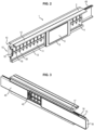
- FIG. 2 shows an information display system 1 intended to be arranged in a sales area according to one embodiment of the invention.
- the system comprises a support 2 adapted to be arranged in the sales area, comprising a receiving space 4 adapted to house a plurality of electronic shelf labels (ESLs) 6, said electronic shelf labels comprising an electronic display screen 8 adapted to display display data.
- ESLs electronic shelf labels
- shelving is distributed throughout a sales area, displaying products offered for sale and composed of several superimposed shelves on which the products are arranged and which delimit aisles forming passageways within the sales area.
- the support 2 is arranged on the shelf edge facing the navigation aisles.
- the support comprises mounting means on said shelves e.g. pegs 10 which snap-fit onto the edge of a shelf via matching shapes.
- the support 2 extends along the edge of a shelf of a sales area display, and houses as many electronic shelf labels 6 as there are different items arranged on the shelf. It is possible to have up to more than ten electronic shelf labels 6 per linear metre of support 2, and hence several thousand even tens of thousands of electric shelf labels in a sales area.
- the support 2 is in the form of a U-shaped rail defining the receiving space 4 delimited by a bottom 11, an upper edge 12 and a lower edge 13, the electronic shelf labels being housed in the receiving space 4 between said bottom 11, the upper edge 12 and lower edge 13.
- the support 2 comprises a module 15 managing the electronic shelf labels 6 and connection lines 40 linking the management module 15 to the receiving space 4.
- the electronic labels management module 15 is configured to manage the electronic shelf labels 6 and more particularly to take in charge their external data communication and/or their electrical powering.
- the electronic labels management module 15 is an electrical module i.e. operating on electrical energy.
- the management module 15 extends along the support 2 behind the bottom 11 of the receiving space 4 i.e. on the side opposite the electronic shelf labels 6.
- the receiving module is located at one end of the support 2.
- connection lines 40 can be designed with a detachable portion 41 joined to the management module 15.
- Connector pins 42 are therefore provided to engage with the portion 41 of the connection lines 40 associated with the management module 15 when inserting the management module 15 in the support 2, to restore electrical continuity of the connection lines 40.
- the management module 15 comprises a communication module 20 adapted to receive display data intended to be displayed by the electronic shelf labels 6.
- the communication module 20 allows wireless communications to be set up with a server sending display data for remote controlling of displayed information by the electronic shelf labels 6.
- These display data are typically product information such as product names and prices associated with each electronic shelf label 6, but they may also comprise other information of sales type.
- This communication module 20 is preferably a radiofrequency receiver which may optionally be a transmitter.
- a location 22 can therefore be reserved for the radio antenna outside the receiving space e.g. at the end of the management module free of connection lines 40. It is also possible to provide for a communication module 20 communicating via infrared or via visible light or any other type of wireless connection.
- the electronic shelf labels 6 are free of any wireless communication system having a range of more than five metres, possibly even of more than one metre. Contrary to prior art systems, communication with the server- optionally via relays from which the electronic shelf labels often lie distant by several metres - is ensured by the management module 15.
- the electronic shelf labels may be provided with a peripheral near field communication device of NFC type (Near Field Communication) or RFID type (Radio Frequency IDentification), generally having a range of less than one metre.
- NFC Near Field Communication
- RFID Radio Frequency IDentification
- the management module comprises at least one self-contained power supply device 30.
- the power supply device 30 is able to store electrical energy and to provide this energy for electrically powering the electronic shelf labels 6 arranged in the receiving space 4.
- the power supply device also allows electrically powering the management module 20.
- the power supply device 30 comprises at least one electric battery cell or electric storage cell and may comprise a series of rechargeable cells forming a battery.
- the power supply device comprises five flat battery cells 32 also called button cells or elements having a total height smaller than the diameter e.g. in the form of a button or coin. They are preferably non-aqueous lithium battery cells.
- These cells 32 are each arranged in a housing 34 having one rounded end 35 to follow the contour of said cells, and one end 36 is open to allow the insertion thereof.
- the polarities of the cells alternate.
- Contactors 37 come into contact with the cell poles to set up electrical contact.
- the electronic shelf labels 6 are free of an electrical storage device allowing self-powering such as an electrical battery cell. Contrary to prior art systems, the electrically powering an electronic shelf label 6 is ensured by the power supply device 30 via the connection lines.
- connection lines 40 are used to connect the management module to the electronic shelf labels 6.
- the connection lines 40 are formed of conductive traces 43 extending along the receiving space from the management module to the surface of a connection plate positioned behind the bottom part of the receiving space.
- a protective cover 45 can be provided to protect the connection plate.
- the bottom of the receiving space 4 comprises a separator plate 50 separating the receiving space 4 from the connection lines 40.
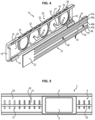
- connection lines 40 In the example illustrated in Figure 4 , the portion 41 of connection lines 40 associated with the management module 15 can be seen. The remainder of the connection lines 40 has the same configuration. Five conductive traces 43 can be seen running parallel on the connection plate and corresponding to five connection lines 40. The number thereof can evidently be adapted according to needs.
- connection lines 40 comprise at least one data transmission line 46a, 46b linking the communication module 20 to the receiving space and adapted to transmit said display data to the electronic shelf labels 6 housed in the receiving space 4.
- connection lines 40 also comprise at least one power supply line 47a, 47b linking the power supply device 30 to the receiving space 4 for electrically powering the electronic shelf labels 6 housed in the receiving space 4.
- two power supply lines 47a, 47b are separated by at least one data transmission line 46a, 46b. In this manner, risks of accidental short circuiting are reduced between the power supply lines 47a, 47b.
- a first trace is a power supply line 47a to which a first supply voltage V+ is applied.
- a second trace is a data transmission line 46a of positive polarity D+.
- a third trace is a data transmission line 46b of negative polarity D-.
- a fourth trace is a power supply line 47b to which a second supply voltage V- is applied.
- the fifth and last trace is an additional connection line 48 which may be used for example to locate the positions of the electronic shelf labels in particular via measurement of an electrical parameter.
- connection plate may also be in two parts, one of which is associated with the management module 15 and detachable from the support 2 when removing the management module 15, whilst the other part remains engaged with the support 2.
- connection plate is secured to the connection module 15 here by means of screws 49 arranged between the two data transmission lines. Similar securing can be used for the part that is not associated with the connection module 15.
- the separator plate 50 forming the bottom 11 of the receiving space 4 has through-holes 51 opposite the connection lines 40 exposing the latter to allow contact between the connection lines 40 arranged behind said separator plate 50 and the electronic shelf labels 6 arranged in the receiving space 4 in front of said separator plate 50.
- the through-holes 51 may extend perpendicular to the direction followed by the receiving space 4 so that one through-hole 51 exposes several connection lines 40.
- the through-holes 51 can be regularly spaced apart in the direction followed by the receiving space 4 e.g. with a spacing of 1 cm.
- a stiffening bar 52 running along the separator plate 50 and secured thereto can be provided to rigidify the receiving space 4.
- the support may comprise locking elements defining predetermined positions for electronic shelf labels 6, the through-holes 51 of the separator plate being arranged facing these predetermined positions.
- an electronic shelf label 6 comprises a casing 61 generally in plastic material, and an electronic display screen 8 adapted to display display data.
- the display screen 8 is typically a low-consumption flat screen or uses electronic ink and can offer different possibilities such as polychrome display or the display of animated sequences.
- the electronic shelf label 6 preferably comprises a locking element matching the locking elements of the support.
- a retractable pin 62 projecting from the casing 61 can be intended to snap-fit into an orifice arranged on one edge of the receiving space 4.
- Application WO98/58360 presents such a locking system for an electronic shelf label.
- the electronic shelf label 6 also comprises connectors 63 adapted to set up a connection between the connection lines 40 and said electronic shelf label 6 to connect said electronic shelf label 6 to the management module 15.
- the connectors 63 are typically formed of a conductive material, typically metal.
- the connectors 63 are arranged at the back 64 of the electronic shelf label, on the side opposite the display screen 8. When the electronic shelf label 6 is placed in position in the receiving space 4 of the support 2, the connectors 63 pass through the through-holes 51 and come into contact with the conductive traces 43 forming the connection lines 40.
- the connectors 63 may comprise a retractable tip 65 drawn outwards by an elastic return member such as a spring.
- Figure 8 illustrates an example of an electronic shelf label 6 mounted in the receiving space 4 of a support between the lower edge and upper edge.
- the locking element 62 of the electronic shelf label can be seen engaged with the matching locking element 66 of the support 2.
- the method to display information in a sales area by means of an information display system 1 such as presented comprises the following steps.
- Display data are sent to the management module 15. More specifically, these display data are sent to the communication module 20 of this management module 15. Preferably they are sent using wireless communication technology. For example, for radiofrequency communications, display data are sent from a transmitter antenna to the antenna of the communication module 20 optionally via radio relays.
- the display data can be communicated to the management module via visible or infrared light.
- These display data are generally derived from a computer server. They typically concern the updating of information relating to the items associated with the electronic shelf labels 6, such as prices.
- the display data comprise an identifier of the electronic shelf label 6 intended to receive said display data.
- Data received by the management module 15 are transmitted to the electronic shelf labels 6 via the connection lines 40 linking the management module to the receiving space 4 in which the electronic shelf labels 6 are housed.
- the display data transit via the data transmission lines 46a, 46b linking the communication module 20 to the receiving space 4 travel through the separator plate 50 via the connectors 63 passing through the through-holes 51 so as to reach the electronic shelf labels 6.
- the electronic shelf label 6 receiving the display data identifies itself by means of identifiers contained in the display data and takes these data into account to determine the information to be displayed by its display screen 8.
Landscapes
- Engineering & Computer Science (AREA)
- Theoretical Computer Science (AREA)
- Physics & Mathematics (AREA)
- General Physics & Mathematics (AREA)
- Human Computer Interaction (AREA)
- General Engineering & Computer Science (AREA)
- Display Racks (AREA)
- Cash Registers Or Receiving Machines (AREA)
Description
- The present invention concerns the association between items in a sales area and locations in said sales area.
- The display of information relating to items offered for sale in a sales area is generally obtained by means of labels displaying the price of the item in particular with which a label is associated, and other information such as price per weight, etc.
- The need to update displayed information has warranted the installation in numerous sales areas of electronic shelf labels (ESLs) provided with a screen on which display of information is remotely controlled.
- The usefulness of such systems is essentially to provide consumers with product information, at the shelving of a sales area such as a supermarket, hypermarket, pharmacy or any other sales area, relating to each item offered for sale e.g. the price that reliably corresponds to information such as contained in the central file of the site i.e. information such as will effectively be used at the cash-out for payment of the item.
- Another advantage of these known systems is to allow automated changes to be made to product information within much shorter times than with manual display, whether for particular periods of on-site special offers, for all or part of the items on sale, for reflecting cost price changes, for keeping up with inflation situations when prices must be very frequently increased, etc.
-
Figure 1 illustrates anassembly 100 formed of arail 101 andESLs 102. Each ESL 102 comprises acasing 103 inside which the functional constituents of said ESL 102 are housed. An ESL has adisplay screen 104 to display information relating to an item with which it is associated. Typically, this information comprises the price of the item and other information usually displayed in a sales area e.g. the price per kilogram for a food product. - In addition, the
ESL 102 comprises a radiofrequency communication module to receive data representing information on an item sent by a central station connected to a computer system, a memory to store said data and a microcontroller to control display of information relating to the item. These different functional constituents are arranged on a printed circuit board housed in thecasing 103. Thecasing 103 also contains a battery cell for electrically powering theESL 102. - The
rail 101 has a U-shaped cross-section and the ESLs 102 are housed in achannel 105 formed by abottom part 106, anupper edge 107 and alower edge 108, the ESLs being housed betweensaid bottom part 106, theupper edge 107 andlower edge 108. - The rail extends over the entire length of the side edge of a
shelf 109 in the sales area and houses asmany ESLs 102 as there are different items arranged on theshelf 109. It is therefore possible to have up to more than tenESLs 102 per metre of rail and hence several thousand even tens of thousands of ESLs within a sales area. - Insofar as an ESL 102 comprises a high number of components, in particular electric and electronic components, an
ESL 102 is therefore a costly device. The large number ofESLs 102 required to equip a sales area therefore amounts to a high cost which may become prohibitive. - It is one objective of the present invention to propose a system to display information in a sales area that is simpler and less costly and has simplified maintenance.
-
US 5 704 049 A discloses an electronic price display system in which a gondola controller has hardwired connections with shelf labels through backbone and rails. -
US 6 181 299 B1 discloses an electrical power system which supplies a/c. power to display tags. A main power distribution loop is connected to the power supply and is magnetically coupled to multiple branch power distribution loops which extend along selected groups of display tags for supplying power to those display tags. -
JP H02 210489 A - One general objective of the invention is to propose a system to display information in a sales area that is more scalable, less costly whilst remaining compatible with conventional electronic shelf label solutions.
- For this purpose there is proposed a support in accordance with claim 1.
- By using an electronic shelf labels management module within the support it is possible to obtain centralised management of several electronic shelf labels connected by the connection lines to said module, and hence to free said labels of at least some of their own management. As a result, the electronic shelf labels are able to offer the same operating functions as in the state of the art but with less complexity.
- The support is advantageously completed by the characteristics of dependent claims 2-7 taken alone or in any technically possible combination.
- There is also proposed a system to display information in a sales area in accordance with
claim 8. - Other characteristics, objectives and advantages of the invention will become apparent from the following description that is solely illustrative and non-limiting and is to be read in connection with the appended drawings amongst which:
-
Figure 1 , already discussed, illustrates a shelf rail and electronic shelf labels in the prior art; -
Figure 2 illustrates an information display system for sales area according to one possible embodiment of the invention, from a three-quarter front view; -
Figure 3 illustrates the installing of an element of the support of the system inFigure 2 , from a three-quarter rear view; -
Figure 4 illustrates the structure of a management module according to one possible embodiment of the invention; -
Figure 5 gives a front view of an electronic shelf label mounted in a support according to one possible embodiment of the invention; -
Figure 6 gives a three-quarter front view of an electronic shelf label according to one possible embodiment of the invention; -
Figure 7 gives a profile view of the electronic shelf label inFigure 6 ; -
Figure 8 is a profile view of an electronic shelf label inFigures 6 and 7 mounted in a support according to one possible embodiment of the invention. -
Figure 2 shows an information display system 1 intended to be arranged in a sales area according to one embodiment of the invention. The system comprises asupport 2 adapted to be arranged in the sales area, comprising a receivingspace 4 adapted to house a plurality of electronic shelf labels (ESLs) 6, said electronic shelf labels comprising anelectronic display screen 8 adapted to display display data. - In the illustrated example, for reasons of simplicity, only a single
electronic shelf label 6 is illustrated arranged in thereceiving space 4 of thesupport 2. Evidently in practice a saidsupport 2 houses a plurality ofelectronic shelf labels 6. - Typically, shelving is distributed throughout a sales area, displaying products offered for sale and composed of several superimposed shelves on which the products are arranged and which delimit aisles forming passageways within the sales area.
- The
support 2 is arranged on the shelf edge facing the navigation aisles. The support comprises mounting means on saidshelves e.g. pegs 10 which snap-fit onto the edge of a shelf via matching shapes. Thesupport 2 extends along the edge of a shelf of a sales area display, and houses as manyelectronic shelf labels 6 as there are different items arranged on the shelf. It is possible to have up to more than tenelectronic shelf labels 6 per linear metre ofsupport 2, and hence several thousand even tens of thousands of electric shelf labels in a sales area. - Typically, and as in the illustrated example, the
support 2 is in the form of a U-shaped rail defining thereceiving space 4 delimited by abottom 11, anupper edge 12 and alower edge 13, the electronic shelf labels being housed in thereceiving space 4 between saidbottom 11, theupper edge 12 andlower edge 13. - The
support 2 comprises amodule 15 managing theelectronic shelf labels 6 andconnection lines 40 linking themanagement module 15 to thereceiving space 4. - The electronic
labels management module 15 is configured to manage theelectronic shelf labels 6 and more particularly to take in charge their external data communication and/or their electrical powering. The electroniclabels management module 15 is an electrical module i.e. operating on electrical energy. - With reference to
Figures 3 to 5 , themanagement module 15 extends along thesupport 2 behind thebottom 11 of thereceiving space 4 i.e. on the side opposite theelectronic shelf labels 6. The receiving module is located at one end of thesupport 2. - The
management module 15 is preferably detachable from thesupport 2 or at least it is mobile relative to thesupport 2 to facilitate maintenance thereof. For this purpose it may comprise projectingparts 16 intended to engage with supportingwings 17 extending from thesupport 2 in the direction away from thereceiving space 4. Anabutment 18 is provided to cooperate with ahousing 19 of thesupport 2 to terminate the travel of themanagement module 15, defining its functional location. - The
connection lines 40 can be designed with adetachable portion 41 joined to themanagement module 15.Connector pins 42 are therefore provided to engage with theportion 41 of theconnection lines 40 associated with themanagement module 15 when inserting themanagement module 15 in thesupport 2, to restore electrical continuity of theconnection lines 40. - The
management module 15 comprises acommunication module 20 adapted to receive display data intended to be displayed by theelectronic shelf labels 6. Thecommunication module 20 allows wireless communications to be set up with a server sending display data for remote controlling of displayed information by theelectronic shelf labels 6. - These display data are typically product information such as product names and prices associated with each
electronic shelf label 6, but they may also comprise other information of sales type. - This
communication module 20 is preferably a radiofrequency receiver which may optionally be a transmitter. Alocation 22 can therefore be reserved for the radio antenna outside the receiving space e.g. at the end of the management module free of connection lines 40. It is also possible to provide for acommunication module 20 communicating via infrared or via visible light or any other type of wireless connection. - The
electronic shelf labels 6 are free of any wireless communication system having a range of more than five metres, possibly even of more than one metre. Contrary to prior art systems, communication with the server- optionally via relays from which the electronic shelf labels often lie distant by several metres - is ensured by themanagement module 15. - On the other hand, the electronic shelf labels may be provided with a peripheral near field communication device of NFC type (Near Field Communication) or RFID type (Radio Frequency IDentification), generally having a range of less than one metre.
- The management module comprises at least one self-contained
power supply device 30. Thepower supply device 30 is able to store electrical energy and to provide this energy for electrically powering theelectronic shelf labels 6 arranged in the receivingspace 4. The power supply device also allows electrically powering themanagement module 20. - The
power supply device 30 comprises at least one electric battery cell or electric storage cell and may comprise a series of rechargeable cells forming a battery. In the illustrated example, the power supply device comprises fiveflat battery cells 32 also called button cells or elements having a total height smaller than the diameter e.g. in the form of a button or coin. They are preferably non-aqueous lithium battery cells. - These
cells 32 are each arranged in ahousing 34 having one rounded end 35 to follow the contour of said cells, and oneend 36 is open to allow the insertion thereof. The polarities of the cells alternate.Contactors 37 come into contact with the cell poles to set up electrical contact. - The
electronic shelf labels 6 are free of an electrical storage device allowing self-powering such as an electrical battery cell. Contrary to prior art systems, the electrically powering anelectronic shelf label 6 is ensured by thepower supply device 30 via the connection lines. - The connection lines 40 are used to connect the management module to the electronic shelf labels 6. The connection lines 40 are formed of
conductive traces 43 extending along the receiving space from the management module to the surface of a connection plate positioned behind the bottom part of the receiving space. Aprotective cover 45 can be provided to protect the connection plate. The bottom of the receivingspace 4 comprises aseparator plate 50 separating the receivingspace 4 from the connection lines 40. - In the example illustrated in
Figure 4 , theportion 41 ofconnection lines 40 associated with themanagement module 15 can be seen. The remainder of the connection lines 40 has the same configuration. Fiveconductive traces 43 can be seen running parallel on the connection plate and corresponding to fiveconnection lines 40. The number thereof can evidently be adapted according to needs. - Therefore the connection lines 40 comprise at least one
data transmission line communication module 20 to the receiving space and adapted to transmit said display data to theelectronic shelf labels 6 housed in the receivingspace 4. - The connection lines 40 also comprise at least one
power supply line power supply device 30 to the receivingspace 4 for electrically powering theelectronic shelf labels 6 housed in the receivingspace 4. - Preferably two
power supply lines data transmission line power supply lines - With more particular reference to
Figure 4 , from top to bottom of the connection plate, a first trace is apower supply line 47a to which a first supply voltage V+ is applied. A second trace is adata transmission line 46a of positive polarity D+. A third trace is adata transmission line 46b of negative polarity D-. A fourth trace is apower supply line 47b to which a second supply voltage V- is applied. - The fifth and last trace is an
additional connection line 48 which may be used for example to locate the positions of the electronic shelf labels in particular via measurement of an electrical parameter. - The connection plate may also be in two parts, one of which is associated with the
management module 15 and detachable from thesupport 2 when removing themanagement module 15, whilst the other part remains engaged with thesupport 2. - The connection plate is secured to the
connection module 15 here by means ofscrews 49 arranged between the two data transmission lines. Similar securing can be used for the part that is not associated with theconnection module 15. - The
separator plate 50 forming the bottom 11 of the receivingspace 4 has through-holes 51 opposite the connection lines 40 exposing the latter to allow contact between the connection lines 40 arranged behind saidseparator plate 50 and theelectronic shelf labels 6 arranged in the receivingspace 4 in front of saidseparator plate 50. - The through-
holes 51, as in the illustrated example, may extend perpendicular to the direction followed by the receivingspace 4 so that one through-hole 51 exposes several connection lines 40. - For example, as in the illustrated example, the through-
holes 51 can be regularly spaced apart in the direction followed by the receivingspace 4 e.g. with a spacing of 1 cm. - A stiffening
bar 52 running along theseparator plate 50 and secured thereto can be provided to rigidify the receivingspace 4. - The support may comprise locking elements defining predetermined positions for
electronic shelf labels 6, the through-holes 51 of the separator plate being arranged facing these predetermined positions. - With reference to
Figures 6 to 8 , anelectronic shelf label 6 comprises acasing 61 generally in plastic material, and anelectronic display screen 8 adapted to display display data. Thedisplay screen 8 is typically a low-consumption flat screen or uses electronic ink and can offer different possibilities such as polychrome display or the display of animated sequences. - The
electronic shelf label 6 preferably comprises a locking element matching the locking elements of the support. For example, as in the illustrated example, aretractable pin 62 projecting from thecasing 61 can be intended to snap-fit into an orifice arranged on one edge of the receivingspace 4. ApplicationWO98/58360 - As can be seen in
Figure 7 , theelectronic shelf label 6 also comprisesconnectors 63 adapted to set up a connection between the connection lines 40 and saidelectronic shelf label 6 to connect saidelectronic shelf label 6 to themanagement module 15. There is at least oneconnector 63 per utilizedconnection line 40. Theconnectors 63 are typically formed of a conductive material, typically metal. - The
connectors 63 are arranged at theback 64 of the electronic shelf label, on the side opposite thedisplay screen 8. When theelectronic shelf label 6 is placed in position in the receivingspace 4 of thesupport 2, theconnectors 63 pass through the through-holes 51 and come into contact with the conductive traces 43 forming the connection lines 40. - To ensure good contact and to facilitate the positioning thereof, the
connectors 63 may comprise aretractable tip 65 drawn outwards by an elastic return member such as a spring. -
Figure 8 illustrates an example of anelectronic shelf label 6 mounted in the receivingspace 4 of a support between the lower edge and upper edge. The lockingelement 62 of the electronic shelf label can be seen engaged with the matching locking element 66 of thesupport 2. - The method to display information in a sales area by means of an information display system 1 such as presented comprises the following steps.
- Display data are sent to the
management module 15. More specifically, these display data are sent to thecommunication module 20 of thismanagement module 15. Preferably they are sent using wireless communication technology. For example, for radiofrequency communications, display data are sent from a transmitter antenna to the antenna of thecommunication module 20 optionally via radio relays. - Other technologies can be used. For example the display data can be communicated to the management module via visible or infrared light.
- These display data are generally derived from a computer server. They typically concern the updating of information relating to the items associated with the
electronic shelf labels 6, such as prices. - The display data comprise an identifier of the
electronic shelf label 6 intended to receive said display data. Data received by themanagement module 15 are transmitted to theelectronic shelf labels 6 via the connection lines 40 linking the management module to the receivingspace 4 in which theelectronic shelf labels 6 are housed. - More specifically, the display data transit via the
data transmission lines communication module 20 to the receivingspace 4, travel through theseparator plate 50 via theconnectors 63 passing through the through-holes 51 so as to reach the electronic shelf labels 6. Theelectronic shelf label 6 receiving the display data identifies itself by means of identifiers contained in the display data and takes these data into account to determine the information to be displayed by itsdisplay screen 8. - In this manner a display system is obtained fulfilling the same functions as prior art systems but with pooling of the members managing the
electronic shelf labels 6, allowing a reduction in the cost and facilitated use thereof. - The invention is not limited to the embodiment described and illustrated in the appended Figures. Modifications remain possible in particular regarding the composition of the various elements or substitution by technical equivalents without departing from the scope of protection of the invention as defined by the appended claims.
Claims (10)
- A support (2) adapted to be arranged in a sales area, comprising:- mounting means (10) configured for arranging the support on a shelf edge facing a navigation aisle of the sales area so as to extend along said shelf edge;- a receiving space (4) configured to allow a back of a plurality of electronic shelf labels to be fitted into said receiving space (6), said electronic shelf labels (6) comprising an electronic display screen (8) adapted to display data,- supporting wings (17) extending from the support (2) in a direction away from the receiving space (4), the supporting wings (17) being configured to engage with projecting parts (16) of an electronic shelf labels management module (15) so as to mount the management module mobile relative to the support and extending along said support (2);- a connection plate positioned behind a bottom part of the receiving space, at the surface of which conductive traces (43) extend along the receiving space (4), the conductive traces forming connection lines which link the management module to the receiving space, and- a separator plate (50) configured to extend facing the electronic shelf labels, between the connection lines (40) and the receiving space (4), said separator plate (50) having through-holes (51) placing the connection lines (40) in communication with the receiving space (4).
- The support according to claim 1, wherein
the connection lines comprise at least one data transmission line (46a, 46b) linking a communication module (20) of the management module (15) to the receiving space (4), wherein the communication module (20) is adapted to receive display data intended to be displayed by the electronic shelf labels and the at least one data transmission line is adapted to transmit said display data to the electronic shelf labels (6) fitted into the receiving space. - The support according to one of claims 1 to 2, wherein the connection lines (40) comprise at least one power supply line (47a, 47b) linking at least one power supply device (30) of the management module (15) to the receiving space for electrically powering the electronic shelf labels (6) fitted into the receiving space (4).
- The support according to any one of claims 1 to 3, wherein the management module (15) extends along the support (2) behind a bottom (11) of the receiving space (4) on the side opposite the electronic shelf labels (6).
- The support according to any one of the preceding claims, wherein the support (2) comprises locking elements defining predetermined positions for electronic shelf labels (6), the through-holes (51) of the separator plate (50) being arranged opposite these predetermined positions.
- The support according to any one of the preceding claims, wherein the support (2) comprises a housing (19), the housing (19) being configured to cooperate with an abutment (18) of the management module (15) to terminate the travel of the management module (15) with respect to the support.
- The support (2) according to any one of the preceding claims, further comprising connector pins (42) provided to engage with a detachable portion (41) of the connection lines (40) associated with the management module (15) when inserting the management module (15) in the support (2).
- An information display system in a sales area, comprising:- an electronic shelf labels management module (15),- a support (2) according to one of claims 1 to 7 comprising connection lines (40) linking the management module (15) to the receiving space (4), andwherein the electronic shelf labels (6) comprise connectors (63) adapted to set up a connection between the connection lines (40) and said electronic shelf labels (6) to connect said electronic shelf labels (6) to the management module, said connectors (63) being configured to pass through the through-holes (51) of the separator plate which faces the electronic shelf labels when the electronic shelf labels are fitted into the receiving space, and wherein the electronic shelf labels (6) are managed by the management module.- a plurality of electronic shelf labels (6) fitted into the receiving space of said support,
- The system of claim 8, wherein the management module (15) comprises at least one communication module (20) adapted to receive display data intended to be displayed by the electronic shelf labels, wherein the communication module (20) is preferentially a radiofrequency module comprising at least one antenna.
- The system of one of claims 8 and 9, wherein the management module (15) comprises at least one power supply device (30), the power supply device (30) being preferentially self-contained and adapted to store electrical energy.
Priority Applications (1)
| Application Number | Priority Date | Filing Date | Title |
|---|---|---|---|
| EP24172330.3A EP4383236A3 (en) | 2016-03-08 | 2017-03-08 | Information display system in a sales area |
Applications Claiming Priority (2)
| Application Number | Priority Date | Filing Date | Title |
|---|---|---|---|
| FR1651909A FR3048806B1 (en) | 2016-03-08 | 2016-03-08 | INFORMATION DISPLAY SYSTEM IN A SALES SURFACE |
| PCT/EP2017/055463 WO2017153481A1 (en) | 2016-03-08 | 2017-03-08 | Information display system in a sales area |
Related Child Applications (2)
| Application Number | Title | Priority Date | Filing Date |
|---|---|---|---|
| EP24172330.3A Division EP4383236A3 (en) | 2016-03-08 | 2017-03-08 | Information display system in a sales area |
| EP24172330.3A Division-Into EP4383236A3 (en) | 2016-03-08 | 2017-03-08 | Information display system in a sales area |
Publications (3)
| Publication Number | Publication Date |
|---|---|
| EP3427144A1 EP3427144A1 (en) | 2019-01-16 |
| EP3427144C0 EP3427144C0 (en) | 2024-06-12 |
| EP3427144B1 true EP3427144B1 (en) | 2024-06-12 |
Family
ID=56741106
Family Applications (2)
| Application Number | Title | Priority Date | Filing Date |
|---|---|---|---|
| EP17709440.6A Active EP3427144B1 (en) | 2016-03-08 | 2017-03-08 | Information display system in a sales area |
| EP24172330.3A Pending EP4383236A3 (en) | 2016-03-08 | 2017-03-08 | Information display system in a sales area |
Family Applications After (1)
| Application Number | Title | Priority Date | Filing Date |
|---|---|---|---|
| EP24172330.3A Pending EP4383236A3 (en) | 2016-03-08 | 2017-03-08 | Information display system in a sales area |
Country Status (7)
| Country | Link |
|---|---|
| US (1) | US10453362B2 (en) |
| EP (2) | EP3427144B1 (en) |
| JP (1) | JP6826125B2 (en) |
| CN (1) | CN109196462B (en) |
| CA (1) | CA3016959C (en) |
| FR (1) | FR3048806B1 (en) |
| WO (1) | WO2017153481A1 (en) |
Families Citing this family (29)
| Publication number | Priority date | Publication date | Assignee | Title |
|---|---|---|---|---|
| US11455912B2 (en) * | 2018-09-07 | 2022-09-27 | Adroit Worldwide Media, Inc. | Electronic shelf-tag systems and methods thereof |
| US11853834B2 (en) | 2019-06-14 | 2023-12-26 | Ses-Imagotag Gmbh | Electronic shelf labelling system with a shelf edge strip sub-system |
| US11948041B2 (en) | 2019-06-14 | 2024-04-02 | Ses-Imagotag Gmbh | Electronic shelf labelling system with a power supply |
| WO2021032278A1 (en) | 2019-08-19 | 2021-02-25 | Ses-Imagotag Gmbh | Electronic shelf tag system with contactless shelf tag power supply and/or data supply |
| FR3099020B1 (en) | 2019-07-15 | 2022-01-14 | Ses Imagotag | Imaging device for a shelf bracket and shelving system comprising the imaging device |
| CN110632668B (en) * | 2019-10-14 | 2024-05-17 | 厦门顶尖电子有限公司 | Electronic price tag positioning method, electronic price tag assembly and system |
| CN210324957U (en) * | 2019-11-19 | 2020-04-14 | 京东方科技集团股份有限公司 | Electronic table board, fixing seat of electronic table board and electronic table board assembly |
| WO2021129933A1 (en) | 2019-12-23 | 2021-07-01 | Ses-Imagotag Gmbh | Electronic shelf labelling system with a shelf edge strip sub-system |
| WO2021129932A1 (en) | 2019-12-23 | 2021-07-01 | Ses-Imagotag Gmbh | Electronic shelf labelling system comprising an energy supply for long-term operation by consumers of a shelf label |
| WO2021142744A1 (en) * | 2020-01-17 | 2021-07-22 | 汉朔科技股份有限公司 | Active electronic shelf label |
| US11232720B2 (en) | 2020-04-30 | 2022-01-25 | Bby Solutions, Inc. | Display holders and adapters system |
| US11275984B1 (en) * | 2020-08-21 | 2022-03-15 | Qualcomm Incorporated | Electronic shelf label (ESL) antenna design |
| USD1049237S1 (en) * | 2020-12-23 | 2024-10-29 | Vusiongroup Gmbh | Shelf assembly set with rail controller and electronic shelf labels |
| CN116888654B (en) | 2020-12-23 | 2026-03-17 | 福森集团有限责任公司 | Fixing element used to secure or fasten the display unit to the carrier device. |
| WO2022188955A1 (en) | 2021-03-09 | 2022-09-15 | Ses-Imagotag Gmbh | Supporting apparatus, in particular rack rail, for supporting an electronic device, preferably an electronic display unit |
| US20240185744A1 (en) | 2021-03-09 | 2024-06-06 | Ses-Imagotag Gmbh | Locating a device on a shelf rail |
| JP7623508B2 (en) | 2021-03-09 | 2025-01-28 | ヴジョングループ・ゲゼルシャフト・ミト・ベシュレンクテル・ハフツング | BUS SYSTEM AND SUPPORT DEVICE EQUIPPED WITH SUCH A BUS SYSTEM - Patent application |
| WO2022218513A1 (en) | 2021-04-13 | 2022-10-20 | Ses-Imagotag Gmbh | Support device for supporting an electronic device within a receiving area for the support device |
| FR3122764B1 (en) * | 2021-05-07 | 2024-06-28 | Captana Gmbh | Shelf imaging device for a shelf support and a shelf system including the shelf imaging device |
| US11967257B2 (en) * | 2021-06-21 | 2024-04-23 | Carl Pomerantz | Retail signage fixture attachment |
| WO2023082017A1 (en) * | 2021-11-15 | 2023-05-19 | Danavation Technologies Corp. | Electronic shelf label and system |
| EP4457792A1 (en) | 2021-12-29 | 2024-11-06 | VusionGroup | Maintenance device for performing maintenance of a shelf rail |
| AU2022437809A1 (en) | 2022-01-28 | 2024-07-04 | Vusiongroup Gmbh | Electronic display device, which can be coupled to an object, for displaying product and/or price information |
| CN115137163A (en) * | 2022-01-28 | 2022-10-04 | 国网江苏省电力有限公司物资分公司 | Intelligent goods and materials goods shelves based on RFID |
| US12446711B2 (en) | 2023-01-31 | 2025-10-21 | Carter-Hoffmann LLC | Heated display cabinet |
| US12022964B1 (en) | 2023-01-31 | 2024-07-02 | Carter-Hoffmann LLC | Heated display cabinet |
| KR20250140073A (en) * | 2023-01-31 | 2025-09-24 | 부전그룹 게엠베하 | Energy storage devices, power supplies and support rail systems that supply electricity to devices that can be mounted on support rails |
| WO2025042323A1 (en) * | 2023-08-21 | 2025-02-27 | Pricer Ab | Electronic shelf label system |
| TWI870065B (en) * | 2023-10-17 | 2025-01-11 | 正美企業股份有限公司 | Electronic shelves |
Citations (4)
| Publication number | Priority date | Publication date | Assignee | Title |
|---|---|---|---|---|
| JPH02210489A (en) * | 1989-02-10 | 1990-08-21 | Hitachi Maxell Ltd | Display |
| US5553412A (en) * | 1993-03-25 | 1996-09-10 | Electronic Retailing Systems International, Inc. | Information display rail system |
| JP2011082138A (en) * | 2009-09-10 | 2011-04-21 | Seiko Instruments Inc | Power feeding device of information display device |
| EP2937830A1 (en) * | 2014-04-25 | 2015-10-28 | Samsung Electro-Mechanics Co., Ltd. | Electronic shelf label tag and electronic shelf label system |
Family Cites Families (23)
| Publication number | Priority date | Publication date | Assignee | Title |
|---|---|---|---|---|
| JPH0375687A (en) * | 1989-08-16 | 1991-03-29 | Hitachi Maxell Ltd | Bin card display system |
| JPH0563615A (en) * | 1991-08-30 | 1993-03-12 | Ncr Corp | Capacitive coupling device |
| US5461561A (en) * | 1991-09-10 | 1995-10-24 | Electronic Retailing Systems International Inc. | System for recognizing display devices |
| US5704049A (en) * | 1992-12-22 | 1997-12-30 | Electronic Retailing Systems International Inc. | Subglobal area addressing for electronic price displays |
| US6181299B1 (en) * | 1993-09-03 | 2001-01-30 | Display Edge Technology, Ltd. | Power and communication system for electronic display tags |
| US5736967A (en) * | 1993-09-03 | 1998-04-07 | Kayser Ventures, Ltd. | Article-information display system using electronically controlled tags |
| FR2765019B1 (en) | 1997-06-18 | 1999-10-15 | Label 41 | ELECTRONIC LABELING SYSTEM |
| US6550673B2 (en) * | 2000-09-19 | 2003-04-22 | Michael J. Massaro | Electronic display for store shelves |
| US6749116B2 (en) * | 2000-09-19 | 2004-06-15 | Michael J. Massaro | Display system for store shelves |
| US6964371B2 (en) * | 2003-05-02 | 2005-11-15 | Atop Technologies Inc. | Electronic display |
| FI124853B (en) * | 2005-02-17 | 2015-02-13 | Marisense Oy | Arrangement for presenting and updating information |
| JP5245239B2 (en) * | 2006-10-25 | 2013-07-24 | セイコーエプソン株式会社 | Product information display device, product information display system, control method and program for product information display system |
| JP2008228752A (en) * | 2007-03-16 | 2008-10-02 | Seiko Epson Corp | Product information display system, display control method and program for product information display system |
| KR100982268B1 (en) * | 2008-10-15 | 2010-09-15 | 삼성전기주식회사 | A price display |
| KR20110110642A (en) * | 2010-04-01 | 2011-10-07 | 엘지이노텍 주식회사 | Digital price indicator |
| KR20120017243A (en) * | 2010-08-18 | 2012-02-28 | 삼성전기주식회사 | Electronic Shelf Labeling System and Communication Method Using the Same |
| US9474177B2 (en) * | 2012-04-26 | 2016-10-18 | Teraoka Seiko Co., Ltd. | Wireless display mount, wireless display mount apparatus, and wireless display system |
| CN102722806B (en) * | 2012-06-11 | 2015-09-23 | 四川航天系统工程研究所 | A kind of Product Management System based on RFID and its implementation |
| KR101365331B1 (en) * | 2012-10-05 | 2014-02-19 | 삼성전기주식회사 | Electronic paper panel and electronic shelf label system and method for driving thereof |
| US20140210692A1 (en) * | 2013-01-25 | 2014-07-31 | Opticon, Inc. | System for remote management of electronic shelf display modules |
| WO2015083005A2 (en) * | 2013-12-04 | 2015-06-11 | Opticon Sensors Europe B.V. | Electronic label system |
| US20150348449A1 (en) * | 2014-05-29 | 2015-12-03 | Samsung Electro-Mechanics Co., Ltd. | Electronic shelf label tag, electronic shelf label system and operating method thereof |
| EP3188110A4 (en) * | 2014-08-26 | 2018-01-24 | Rainus Co. Ltd. | Display-integrated information display system |
-
2016
- 2016-03-08 FR FR1651909A patent/FR3048806B1/en active Active
-
2017
- 2017-03-08 CA CA3016959A patent/CA3016959C/en active Active
- 2017-03-08 EP EP17709440.6A patent/EP3427144B1/en active Active
- 2017-03-08 EP EP24172330.3A patent/EP4383236A3/en active Pending
- 2017-03-08 US US16/083,248 patent/US10453362B2/en active Active
- 2017-03-08 CN CN201780016222.4A patent/CN109196462B/en active Active
- 2017-03-08 JP JP2018547395A patent/JP6826125B2/en active Active
- 2017-03-08 WO PCT/EP2017/055463 patent/WO2017153481A1/en not_active Ceased
Patent Citations (4)
| Publication number | Priority date | Publication date | Assignee | Title |
|---|---|---|---|---|
| JPH02210489A (en) * | 1989-02-10 | 1990-08-21 | Hitachi Maxell Ltd | Display |
| US5553412A (en) * | 1993-03-25 | 1996-09-10 | Electronic Retailing Systems International, Inc. | Information display rail system |
| JP2011082138A (en) * | 2009-09-10 | 2011-04-21 | Seiko Instruments Inc | Power feeding device of information display device |
| EP2937830A1 (en) * | 2014-04-25 | 2015-10-28 | Samsung Electro-Mechanics Co., Ltd. | Electronic shelf label tag and electronic shelf label system |
Also Published As
| Publication number | Publication date |
|---|---|
| EP3427144A1 (en) | 2019-01-16 |
| JP6826125B2 (en) | 2021-02-03 |
| EP4383236A2 (en) | 2024-06-12 |
| US10453362B2 (en) | 2019-10-22 |
| EP3427144C0 (en) | 2024-06-12 |
| CA3016959A1 (en) | 2017-09-14 |
| FR3048806B1 (en) | 2019-07-05 |
| US20190080633A1 (en) | 2019-03-14 |
| CN109196462A (en) | 2019-01-11 |
| CA3016959C (en) | 2024-03-12 |
| CN109196462B (en) | 2022-05-31 |
| WO2017153481A1 (en) | 2017-09-14 |
| EP4383236A3 (en) | 2024-07-10 |
| JP2019517283A (en) | 2019-06-24 |
| FR3048806A1 (en) | 2017-09-15 |
Similar Documents
| Publication | Publication Date | Title |
|---|---|---|
| CA3016959C (en) | Information display system in a sales area | |
| US9559414B2 (en) | Arrangement for reducing interference in an electronic shelf label | |
| CN102542420A (en) | Electronic shelf label system | |
| CN114222994A (en) | Electronic shelf label system with contactless shelf label energy and/or data supply | |
| JPH08234677A (en) | Electronic display module | |
| KR20120077949A (en) | An eletronic shelf label and a managing method thereof | |
| US20130036636A1 (en) | Wireless electronic shelf label | |
| US20180004472A1 (en) | Electronic price label and a battery unit for an electronic price label | |
| US20110205201A1 (en) | Microencapsulated electrophoretic price display system | |
| US10769969B2 (en) | Electronic shelf display tag and powered shelf support track system, apparatus and method of use | |
| CN202533995U (en) | Electronic shelf label system | |
| WO2015083005A2 (en) | Electronic label system | |
| US11735076B2 (en) | Electronic display and a display module, especially for shopping carts | |
| CN107330486A (en) | Electronic shelf label module and electronic bin tag system | |
| US11948041B2 (en) | Electronic shelf labelling system with a power supply | |
| KR20160066357A (en) | Rail for Electronic Shelf Label | |
| EP2064691A1 (en) | Arrangement for data display units | |
| CN211699563U (en) | Electronic label system | |
| CN207676580U (en) | Electronic bin tag system component and its sub- control module | |
| KR101273745B1 (en) | Electronic shelf lable tag | |
| CN112270387A (en) | Electronic shelf label system | |
| CN107492312A (en) | Electronic bin tag system component and its sub- control module | |
| CN207164786U (en) | Electronic shelf label module and electronic bin tag system | |
| WO2015144982A1 (en) | Electronic price label and an electronic price label system | |
| KR20250110980A (en) | Electronic display rail system |
Legal Events
| Date | Code | Title | Description |
|---|---|---|---|
| STAA | Information on the status of an ep patent application or granted ep patent |
Free format text: STATUS: UNKNOWN |
|
| STAA | Information on the status of an ep patent application or granted ep patent |
Free format text: STATUS: THE INTERNATIONAL PUBLICATION HAS BEEN MADE |
|
| PUAI | Public reference made under article 153(3) epc to a published international application that has entered the european phase |
Free format text: ORIGINAL CODE: 0009012 |
|
| STAA | Information on the status of an ep patent application or granted ep patent |
Free format text: STATUS: REQUEST FOR EXAMINATION WAS MADE |
|
| 17P | Request for examination filed |
Effective date: 20181005 |
|
| AK | Designated contracting states |
Kind code of ref document: A1 Designated state(s): AL AT BE BG CH CY CZ DE DK EE ES FI FR GB GR HR HU IE IS IT LI LT LU LV MC MK MT NL NO PL PT RO RS SE SI SK SM TR |
|
| AX | Request for extension of the european patent |
Extension state: BA ME |
|
| DAV | Request for validation of the european patent (deleted) | ||
| DAX | Request for extension of the european patent (deleted) | ||
| STAA | Information on the status of an ep patent application or granted ep patent |
Free format text: STATUS: EXAMINATION IS IN PROGRESS |
|
| 17Q | First examination report despatched |
Effective date: 20210430 |
|
| P01 | Opt-out of the competence of the unified patent court (upc) registered |
Effective date: 20230428 |
|
| GRAP | Despatch of communication of intention to grant a patent |
Free format text: ORIGINAL CODE: EPIDOSNIGR1 |
|
| STAA | Information on the status of an ep patent application or granted ep patent |
Free format text: STATUS: GRANT OF PATENT IS INTENDED |
|
| INTG | Intention to grant announced |
Effective date: 20240131 |
|
| RAP3 | Party data changed (applicant data changed or rights of an application transferred) |
Owner name: VUSIONGROUP |
|
| GRAS | Grant fee paid |
Free format text: ORIGINAL CODE: EPIDOSNIGR3 |
|
| GRAA | (expected) grant |
Free format text: ORIGINAL CODE: 0009210 |
|
| STAA | Information on the status of an ep patent application or granted ep patent |
Free format text: STATUS: THE PATENT HAS BEEN GRANTED |
|
| AK | Designated contracting states |
Kind code of ref document: B1 Designated state(s): AL AT BE BG CH CY CZ DE DK EE ES FI FR GB GR HR HU IE IS IT LI LT LU LV MC MK MT NL NO PL PT RO RS SE SI SK SM TR |
|
| REG | Reference to a national code |
Ref country code: GB Ref legal event code: FG4D |
|
| REG | Reference to a national code |
Ref country code: CH Ref legal event code: EP |
|
| REG | Reference to a national code |
Ref country code: DE Ref legal event code: R096 Ref document number: 602017082522 Country of ref document: DE |
|
| REG | Reference to a national code |
Ref country code: IE Ref legal event code: FG4D |
|
| U01 | Request for unitary effect filed |
Effective date: 20240712 |
|
| P04 | Withdrawal of opt-out of the competence of the unified patent court (upc) registered |
Free format text: CASE NUMBER: APP_48688/2024 Effective date: 20240826 |
|
| U07 | Unitary effect registered |
Designated state(s): AT BE BG DE DK EE FI FR IT LT LU LV MT NL PT RO SE SI Effective date: 20240902 |
|
| PG25 | Lapsed in a contracting state [announced via postgrant information from national office to epo] |
Ref country code: HR Free format text: LAPSE BECAUSE OF FAILURE TO SUBMIT A TRANSLATION OF THE DESCRIPTION OR TO PAY THE FEE WITHIN THE PRESCRIBED TIME-LIMIT Effective date: 20240612 |
|
| PG25 | Lapsed in a contracting state [announced via postgrant information from national office to epo] |
Ref country code: GR Free format text: LAPSE BECAUSE OF FAILURE TO SUBMIT A TRANSLATION OF THE DESCRIPTION OR TO PAY THE FEE WITHIN THE PRESCRIBED TIME-LIMIT Effective date: 20240913 |
|
| PG25 | Lapsed in a contracting state [announced via postgrant information from national office to epo] |
Ref country code: ES Free format text: LAPSE BECAUSE OF FAILURE TO SUBMIT A TRANSLATION OF THE DESCRIPTION OR TO PAY THE FEE WITHIN THE PRESCRIBED TIME-LIMIT Effective date: 20240612 |
|
| PG25 | Lapsed in a contracting state [announced via postgrant information from national office to epo] |
Ref country code: NO Free format text: LAPSE BECAUSE OF FAILURE TO SUBMIT A TRANSLATION OF THE DESCRIPTION OR TO PAY THE FEE WITHIN THE PRESCRIBED TIME-LIMIT Effective date: 20240912 Ref country code: HR Free format text: LAPSE BECAUSE OF FAILURE TO SUBMIT A TRANSLATION OF THE DESCRIPTION OR TO PAY THE FEE WITHIN THE PRESCRIBED TIME-LIMIT Effective date: 20240612 Ref country code: GR Free format text: LAPSE BECAUSE OF FAILURE TO SUBMIT A TRANSLATION OF THE DESCRIPTION OR TO PAY THE FEE WITHIN THE PRESCRIBED TIME-LIMIT Effective date: 20240913 Ref country code: ES Free format text: LAPSE BECAUSE OF FAILURE TO SUBMIT A TRANSLATION OF THE DESCRIPTION OR TO PAY THE FEE WITHIN THE PRESCRIBED TIME-LIMIT Effective date: 20240612 Ref country code: RS Free format text: LAPSE BECAUSE OF FAILURE TO SUBMIT A TRANSLATION OF THE DESCRIPTION OR TO PAY THE FEE WITHIN THE PRESCRIBED TIME-LIMIT Effective date: 20240912 |
|
| P05 | Withdrawal of opt-out of the competence of the unified patent court (upc) changed |
Free format text: CASE NUMBER: APP_48688/2024 Effective date: 20240902 |
|
| PG25 | Lapsed in a contracting state [announced via postgrant information from national office to epo] |
Ref country code: PL Free format text: LAPSE BECAUSE OF FAILURE TO SUBMIT A TRANSLATION OF THE DESCRIPTION OR TO PAY THE FEE WITHIN THE PRESCRIBED TIME-LIMIT Effective date: 20240612 |
|
| PG25 | Lapsed in a contracting state [announced via postgrant information from national office to epo] |
Ref country code: IS Free format text: LAPSE BECAUSE OF FAILURE TO SUBMIT A TRANSLATION OF THE DESCRIPTION OR TO PAY THE FEE WITHIN THE PRESCRIBED TIME-LIMIT Effective date: 20241012 |
|
| PG25 | Lapsed in a contracting state [announced via postgrant information from national office to epo] |
Ref country code: CZ Free format text: LAPSE BECAUSE OF FAILURE TO SUBMIT A TRANSLATION OF THE DESCRIPTION OR TO PAY THE FEE WITHIN THE PRESCRIBED TIME-LIMIT Effective date: 20240612 |
|
| PG25 | Lapsed in a contracting state [announced via postgrant information from national office to epo] |
Ref country code: SK Free format text: LAPSE BECAUSE OF FAILURE TO SUBMIT A TRANSLATION OF THE DESCRIPTION OR TO PAY THE FEE WITHIN THE PRESCRIBED TIME-LIMIT Effective date: 20240612 |
|
| PG25 | Lapsed in a contracting state [announced via postgrant information from national office to epo] |
Ref country code: SM Free format text: LAPSE BECAUSE OF FAILURE TO SUBMIT A TRANSLATION OF THE DESCRIPTION OR TO PAY THE FEE WITHIN THE PRESCRIBED TIME-LIMIT Effective date: 20240612 |
|
| PG25 | Lapsed in a contracting state [announced via postgrant information from national office to epo] |
Ref country code: SM Free format text: LAPSE BECAUSE OF FAILURE TO SUBMIT A TRANSLATION OF THE DESCRIPTION OR TO PAY THE FEE WITHIN THE PRESCRIBED TIME-LIMIT Effective date: 20240612 Ref country code: SK Free format text: LAPSE BECAUSE OF FAILURE TO SUBMIT A TRANSLATION OF THE DESCRIPTION OR TO PAY THE FEE WITHIN THE PRESCRIBED TIME-LIMIT Effective date: 20240612 Ref country code: PL Free format text: LAPSE BECAUSE OF FAILURE TO SUBMIT A TRANSLATION OF THE DESCRIPTION OR TO PAY THE FEE WITHIN THE PRESCRIBED TIME-LIMIT Effective date: 20240612 Ref country code: IS Free format text: LAPSE BECAUSE OF FAILURE TO SUBMIT A TRANSLATION OF THE DESCRIPTION OR TO PAY THE FEE WITHIN THE PRESCRIBED TIME-LIMIT Effective date: 20241012 Ref country code: CZ Free format text: LAPSE BECAUSE OF FAILURE TO SUBMIT A TRANSLATION OF THE DESCRIPTION OR TO PAY THE FEE WITHIN THE PRESCRIBED TIME-LIMIT Effective date: 20240612 |
|
| U20 | Renewal fee for the european patent with unitary effect paid |
Year of fee payment: 9 Effective date: 20250211 |
|
| PLBE | No opposition filed within time limit |
Free format text: ORIGINAL CODE: 0009261 |
|
| STAA | Information on the status of an ep patent application or granted ep patent |
Free format text: STATUS: NO OPPOSITION FILED WITHIN TIME LIMIT |
|
| 26N | No opposition filed |
Effective date: 20250313 |
|
| PG25 | Lapsed in a contracting state [announced via postgrant information from national office to epo] |
Ref country code: MC Free format text: LAPSE BECAUSE OF FAILURE TO SUBMIT A TRANSLATION OF THE DESCRIPTION OR TO PAY THE FEE WITHIN THE PRESCRIBED TIME-LIMIT Effective date: 20240612 |
|
| REG | Reference to a national code |
Ref country code: CH Ref legal event code: H13 Free format text: ST27 STATUS EVENT CODE: U-0-0-H10-H13 (AS PROVIDED BY THE NATIONAL OFFICE) Effective date: 20251023 |
|
| GBPC | Gb: european patent ceased through non-payment of renewal fee |
Effective date: 20250308 |
|
| PG25 | Lapsed in a contracting state [announced via postgrant information from national office to epo] |
Ref country code: GB Free format text: LAPSE BECAUSE OF NON-PAYMENT OF DUE FEES Effective date: 20250308 |
|
| PG25 | Lapsed in a contracting state [announced via postgrant information from national office to epo] |
Ref country code: CH Free format text: LAPSE BECAUSE OF NON-PAYMENT OF DUE FEES Effective date: 20250331 |
|
| PG25 | Lapsed in a contracting state [announced via postgrant information from national office to epo] |
Ref country code: IE Free format text: LAPSE BECAUSE OF NON-PAYMENT OF DUE FEES Effective date: 20250308 |
|
| U20 | Renewal fee for the european patent with unitary effect paid |
Year of fee payment: 10 Effective date: 20260211 |