EP3426567B1 - Gas canisters and methods for making them - Google Patents
Gas canisters and methods for making them Download PDFInfo
- Publication number
- EP3426567B1 EP3426567B1 EP17717015.6A EP17717015A EP3426567B1 EP 3426567 B1 EP3426567 B1 EP 3426567B1 EP 17717015 A EP17717015 A EP 17717015A EP 3426567 B1 EP3426567 B1 EP 3426567B1
- Authority
- EP
- European Patent Office
- Prior art keywords
- cap
- canister
- septum
- elongate body
- region
- Prior art date
- Legal status (The legal status is an assumption and is not a legal conclusion. Google has not performed a legal analysis and makes no representation as to the accuracy of the status listed.)
- Active
Links
Images






Classifications
-
- A—HUMAN NECESSITIES
- A61—MEDICAL OR VETERINARY SCIENCE; HYGIENE
- A61B—DIAGNOSIS; SURGERY; IDENTIFICATION
- A61B17/00—Surgical instruments, devices or methods
- A61B17/34—Trocars; Puncturing needles
- A61B17/3417—Details of tips or shafts, e.g. grooves, expandable, bendable; Multiple coaxial sliding cannulas, e.g. for dilating
- A61B17/3421—Cannulas
-
- A—HUMAN NECESSITIES
- A61—MEDICAL OR VETERINARY SCIENCE; HYGIENE
- A61B—DIAGNOSIS; SURGERY; IDENTIFICATION
- A61B17/00—Surgical instruments, devices or methods
- A61B17/34—Trocars; Puncturing needles
- A61B17/3468—Trocars; Puncturing needles for implanting or removing devices, e.g. prostheses, implants, seeds, wires
-
- A—HUMAN NECESSITIES
- A61—MEDICAL OR VETERINARY SCIENCE; HYGIENE
- A61F—FILTERS IMPLANTABLE INTO BLOOD VESSELS; PROSTHESES; DEVICES PROVIDING PATENCY TO, OR PREVENTING COLLAPSING OF, TUBULAR STRUCTURES OF THE BODY, e.g. STENTS; ORTHOPAEDIC, NURSING OR CONTRACEPTIVE DEVICES; FOMENTATION; TREATMENT OR PROTECTION OF EYES OR EARS; BANDAGES, DRESSINGS OR ABSORBENT PADS; FIRST-AID KITS
- A61F2/00—Filters implantable into blood vessels; Prostheses, i.e. artificial substitutes or replacements for parts of the body; Appliances for connecting them with the body; Devices providing patency to, or preventing collapsing of, tubular structures of the body, e.g. stents
- A61F2/02—Prostheses implantable into the body
- A61F2/14—Eye parts, e.g. lenses or corneal implants; Artificial eyes
-
- A—HUMAN NECESSITIES
- A61—MEDICAL OR VETERINARY SCIENCE; HYGIENE
- A61F—FILTERS IMPLANTABLE INTO BLOOD VESSELS; PROSTHESES; DEVICES PROVIDING PATENCY TO, OR PREVENTING COLLAPSING OF, TUBULAR STRUCTURES OF THE BODY, e.g. STENTS; ORTHOPAEDIC, NURSING OR CONTRACEPTIVE DEVICES; FOMENTATION; TREATMENT OR PROTECTION OF EYES OR EARS; BANDAGES, DRESSINGS OR ABSORBENT PADS; FIRST-AID KITS
- A61F2/00—Filters implantable into blood vessels; Prostheses, i.e. artificial substitutes or replacements for parts of the body; Appliances for connecting them with the body; Devices providing patency to, or preventing collapsing of, tubular structures of the body, e.g. stents
- A61F2/02—Prostheses implantable into the body
- A61F2/14—Eye parts, e.g. lenses or corneal implants; Artificial eyes
- A61F2/148—Implantation instruments specially adapted therefor
-
- A—HUMAN NECESSITIES
- A61—MEDICAL OR VETERINARY SCIENCE; HYGIENE
- A61F—FILTERS IMPLANTABLE INTO BLOOD VESSELS; PROSTHESES; DEVICES PROVIDING PATENCY TO, OR PREVENTING COLLAPSING OF, TUBULAR STRUCTURES OF THE BODY, e.g. STENTS; ORTHOPAEDIC, NURSING OR CONTRACEPTIVE DEVICES; FOMENTATION; TREATMENT OR PROTECTION OF EYES OR EARS; BANDAGES, DRESSINGS OR ABSORBENT PADS; FIRST-AID KITS
- A61F2/00—Filters implantable into blood vessels; Prostheses, i.e. artificial substitutes or replacements for parts of the body; Appliances for connecting them with the body; Devices providing patency to, or preventing collapsing of, tubular structures of the body, e.g. stents
- A61F2/02—Prostheses implantable into the body
- A61F2/14—Eye parts, e.g. lenses or corneal implants; Artificial eyes
- A61F2/16—Intraocular lenses
- A61F2/1662—Instruments for inserting intraocular lenses into the eye
- A61F2/167—Instruments for inserting intraocular lenses into the eye with pushable plungers
-
- A—HUMAN NECESSITIES
- A61—MEDICAL OR VETERINARY SCIENCE; HYGIENE
- A61F—FILTERS IMPLANTABLE INTO BLOOD VESSELS; PROSTHESES; DEVICES PROVIDING PATENCY TO, OR PREVENTING COLLAPSING OF, TUBULAR STRUCTURES OF THE BODY, e.g. STENTS; ORTHOPAEDIC, NURSING OR CONTRACEPTIVE DEVICES; FOMENTATION; TREATMENT OR PROTECTION OF EYES OR EARS; BANDAGES, DRESSINGS OR ABSORBENT PADS; FIRST-AID KITS
- A61F2/00—Filters implantable into blood vessels; Prostheses, i.e. artificial substitutes or replacements for parts of the body; Appliances for connecting them with the body; Devices providing patency to, or preventing collapsing of, tubular structures of the body, e.g. stents
- A61F2/02—Prostheses implantable into the body
- A61F2/14—Eye parts, e.g. lenses or corneal implants; Artificial eyes
- A61F2/16—Intraocular lenses
- A61F2/1662—Instruments for inserting intraocular lenses into the eye
- A61F2/1678—Instruments for inserting intraocular lenses into the eye with a separate cartridge or other lens setting part for storage of a lens, e.g. preloadable for shipping
-
- A—HUMAN NECESSITIES
- A61—MEDICAL OR VETERINARY SCIENCE; HYGIENE
- A61M—DEVICES FOR INTRODUCING MEDIA INTO, OR ONTO, THE BODY; DEVICES FOR TRANSDUCING BODY MEDIA OR FOR TAKING MEDIA FROM THE BODY; DEVICES FOR PRODUCING OR ENDING SLEEP OR STUPOR
- A61M5/00—Devices for bringing media into the body in a subcutaneous, intra-vascular or intramuscular way; Accessories therefor, e.g. filling or cleaning devices, arm-rests
- A61M5/178—Syringes
- A61M5/20—Automatic syringes, e.g. with automatically actuated piston rod, with automatic needle injection, filling automatically
- A61M5/2053—Media being expelled from injector by pressurised fluid or vacuum
-
- B—PERFORMING OPERATIONS; TRANSPORTING
- B65—CONVEYING; PACKING; STORING; HANDLING THIN OR FILAMENTARY MATERIAL
- B65D—CONTAINERS FOR STORAGE OR TRANSPORT OF ARTICLES OR MATERIALS, e.g. BAGS, BARRELS, BOTTLES, BOXES, CANS, CARTONS, CRATES, DRUMS, JARS, TANKS, HOPPERS, FORWARDING CONTAINERS; ACCESSORIES, CLOSURES, OR FITTINGS THEREFOR; PACKAGING ELEMENTS; PACKAGES
- B65D41/00—Caps, e.g. crown caps or crown seals, i.e. members having parts arranged for engagement with the external periphery of a neck or wall defining a pouring opening or discharge aperture; Protective cap-like covers for closure members, e.g. decorative covers of metal foil or paper
- B65D41/02—Caps or cap-like covers without lines of weakness, tearing strips, tags, or like opening or removal devices
- B65D41/20—Caps or cap-like covers with membranes, e.g. arranged to be pierced
-
- F—MECHANICAL ENGINEERING; LIGHTING; HEATING; WEAPONS; BLASTING
- F17—STORING OR DISTRIBUTING GASES OR LIQUIDS
- F17C—VESSELS FOR CONTAINING OR STORING COMPRESSED, LIQUEFIED OR SOLIDIFIED GASES; FIXED-CAPACITY GAS-HOLDERS; FILLING VESSELS WITH, OR DISCHARGING FROM VESSELS, COMPRESSED, LIQUEFIED, OR SOLIDIFIED GASES
- F17C1/00—Pressure vessels, e.g. gas cylinder, gas tank, replaceable cartridge
-
- F—MECHANICAL ENGINEERING; LIGHTING; HEATING; WEAPONS; BLASTING
- F17—STORING OR DISTRIBUTING GASES OR LIQUIDS
- F17C—VESSELS FOR CONTAINING OR STORING COMPRESSED, LIQUEFIED OR SOLIDIFIED GASES; FIXED-CAPACITY GAS-HOLDERS; FILLING VESSELS WITH, OR DISCHARGING FROM VESSELS, COMPRESSED, LIQUEFIED, OR SOLIDIFIED GASES
- F17C13/00—Details of vessels or of the filling or discharging of vessels
- F17C13/04—Arrangement or mounting of valves
-
- F—MECHANICAL ENGINEERING; LIGHTING; HEATING; WEAPONS; BLASTING
- F17—STORING OR DISTRIBUTING GASES OR LIQUIDS
- F17C—VESSELS FOR CONTAINING OR STORING COMPRESSED, LIQUEFIED OR SOLIDIFIED GASES; FIXED-CAPACITY GAS-HOLDERS; FILLING VESSELS WITH, OR DISCHARGING FROM VESSELS, COMPRESSED, LIQUEFIED, OR SOLIDIFIED GASES
- F17C13/00—Details of vessels or of the filling or discharging of vessels
- F17C13/06—Closures, e.g. cap, breakable member
-
- A—HUMAN NECESSITIES
- A61—MEDICAL OR VETERINARY SCIENCE; HYGIENE
- A61B—DIAGNOSIS; SURGERY; IDENTIFICATION
- A61B17/00—Surgical instruments, devices or methods
-
- A—HUMAN NECESSITIES
- A61—MEDICAL OR VETERINARY SCIENCE; HYGIENE
- A61B—DIAGNOSIS; SURGERY; IDENTIFICATION
- A61B17/00—Surgical instruments, devices or methods
- A61B2017/00367—Details of actuation of instruments, e.g. relations between pushing buttons, or the like, and activation of the tool, working tip, or the like
- A61B2017/00398—Details of actuation of instruments, e.g. relations between pushing buttons, or the like, and activation of the tool, working tip, or the like using powered actuators, e.g. stepper motors, solenoids
-
- A—HUMAN NECESSITIES
- A61—MEDICAL OR VETERINARY SCIENCE; HYGIENE
- A61B—DIAGNOSIS; SURGERY; IDENTIFICATION
- A61B17/00—Surgical instruments, devices or methods
- A61B2017/00526—Methods of manufacturing
-
- A—HUMAN NECESSITIES
- A61—MEDICAL OR VETERINARY SCIENCE; HYGIENE
- A61B—DIAGNOSIS; SURGERY; IDENTIFICATION
- A61B17/00—Surgical instruments, devices or methods
- A61B2017/00535—Surgical instruments, devices or methods pneumatically or hydraulically operated
- A61B2017/00544—Surgical instruments, devices or methods pneumatically or hydraulically operated pneumatically
- A61B2017/00548—Gas cartridges therefor
-
- A—HUMAN NECESSITIES
- A61—MEDICAL OR VETERINARY SCIENCE; HYGIENE
- A61B—DIAGNOSIS; SURGERY; IDENTIFICATION
- A61B17/00—Surgical instruments, devices or methods
- A61B17/34—Trocars; Puncturing needles
- A61B17/3403—Needle locating or guiding means
- A61B2017/3405—Needle locating or guiding means using mechanical guide means
- A61B2017/3409—Needle locating or guiding means using mechanical guide means including needle or instrument drives
-
- A—HUMAN NECESSITIES
- A61—MEDICAL OR VETERINARY SCIENCE; HYGIENE
- A61F—FILTERS IMPLANTABLE INTO BLOOD VESSELS; PROSTHESES; DEVICES PROVIDING PATENCY TO, OR PREVENTING COLLAPSING OF, TUBULAR STRUCTURES OF THE BODY, e.g. STENTS; ORTHOPAEDIC, NURSING OR CONTRACEPTIVE DEVICES; FOMENTATION; TREATMENT OR PROTECTION OF EYES OR EARS; BANDAGES, DRESSINGS OR ABSORBENT PADS; FIRST-AID KITS
- A61F2/00—Filters implantable into blood vessels; Prostheses, i.e. artificial substitutes or replacements for parts of the body; Appliances for connecting them with the body; Devices providing patency to, or preventing collapsing of, tubular structures of the body, e.g. stents
- A61F2/02—Prostheses implantable into the body
- A61F2/14—Eye parts, e.g. lenses or corneal implants; Artificial eyes
- A61F2/16—Intraocular lenses
- A61F2/1662—Instruments for inserting intraocular lenses into the eye
-
- A—HUMAN NECESSITIES
- A61—MEDICAL OR VETERINARY SCIENCE; HYGIENE
- A61M—DEVICES FOR INTRODUCING MEDIA INTO, OR ONTO, THE BODY; DEVICES FOR TRANSDUCING BODY MEDIA OR FOR TAKING MEDIA FROM THE BODY; DEVICES FOR PRODUCING OR ENDING SLEEP OR STUPOR
- A61M11/00—Sprayers or atomisers specially adapted for therapeutic purposes
- A61M11/02—Sprayers or atomisers specially adapted for therapeutic purposes operated by air or other gas pressure applied to the liquid or other product to be sprayed or atomised
-
- A—HUMAN NECESSITIES
- A61—MEDICAL OR VETERINARY SCIENCE; HYGIENE
- A61M—DEVICES FOR INTRODUCING MEDIA INTO, OR ONTO, THE BODY; DEVICES FOR TRANSDUCING BODY MEDIA OR FOR TAKING MEDIA FROM THE BODY; DEVICES FOR PRODUCING OR ENDING SLEEP OR STUPOR
- A61M2205/00—General characteristics of the apparatus
- A61M2205/82—Internal energy supply devices
- A61M2205/8218—Gas operated
- A61M2205/8225—Gas operated using incorporated gas cartridges for the driving gas
-
- B—PERFORMING OPERATIONS; TRANSPORTING
- B65—CONVEYING; PACKING; STORING; HANDLING THIN OR FILAMENTARY MATERIAL
- B65B—MACHINES, APPARATUS OR DEVICES FOR, OR METHODS OF, PACKAGING ARTICLES OR MATERIALS; UNPACKING
- B65B31/00—Packaging articles or materials under special atmospheric or gaseous conditions; Adding propellants to aerosol containers
- B65B31/003—Adding propellants in fluid form to aerosol containers
-
- F—MECHANICAL ENGINEERING; LIGHTING; HEATING; WEAPONS; BLASTING
- F17—STORING OR DISTRIBUTING GASES OR LIQUIDS
- F17C—VESSELS FOR CONTAINING OR STORING COMPRESSED, LIQUEFIED OR SOLIDIFIED GASES; FIXED-CAPACITY GAS-HOLDERS; FILLING VESSELS WITH, OR DISCHARGING FROM VESSELS, COMPRESSED, LIQUEFIED, OR SOLIDIFIED GASES
- F17C2201/00—Vessel construction, in particular geometry, arrangement or size
- F17C2201/01—Shape
- F17C2201/0104—Shape cylindrical
- F17C2201/0109—Shape cylindrical with exteriorly curved end-piece
-
- F—MECHANICAL ENGINEERING; LIGHTING; HEATING; WEAPONS; BLASTING
- F17—STORING OR DISTRIBUTING GASES OR LIQUIDS
- F17C—VESSELS FOR CONTAINING OR STORING COMPRESSED, LIQUEFIED OR SOLIDIFIED GASES; FIXED-CAPACITY GAS-HOLDERS; FILLING VESSELS WITH, OR DISCHARGING FROM VESSELS, COMPRESSED, LIQUEFIED, OR SOLIDIFIED GASES
- F17C2201/00—Vessel construction, in particular geometry, arrangement or size
- F17C2201/05—Size
- F17C2201/058—Size portable (<30 l)
-
- F—MECHANICAL ENGINEERING; LIGHTING; HEATING; WEAPONS; BLASTING
- F17—STORING OR DISTRIBUTING GASES OR LIQUIDS
- F17C—VESSELS FOR CONTAINING OR STORING COMPRESSED, LIQUEFIED OR SOLIDIFIED GASES; FIXED-CAPACITY GAS-HOLDERS; FILLING VESSELS WITH, OR DISCHARGING FROM VESSELS, COMPRESSED, LIQUEFIED, OR SOLIDIFIED GASES
- F17C2203/00—Vessel construction, in particular walls or details thereof
- F17C2203/06—Materials for walls or layers thereof; Properties or structures of walls or their materials
- F17C2203/0602—Wall structures; Special features thereof
- F17C2203/0612—Wall structures
- F17C2203/0614—Single wall
- F17C2203/0617—Single wall with one layer
-
- F—MECHANICAL ENGINEERING; LIGHTING; HEATING; WEAPONS; BLASTING
- F17—STORING OR DISTRIBUTING GASES OR LIQUIDS
- F17C—VESSELS FOR CONTAINING OR STORING COMPRESSED, LIQUEFIED OR SOLIDIFIED GASES; FIXED-CAPACITY GAS-HOLDERS; FILLING VESSELS WITH, OR DISCHARGING FROM VESSELS, COMPRESSED, LIQUEFIED, OR SOLIDIFIED GASES
- F17C2203/00—Vessel construction, in particular walls or details thereof
- F17C2203/06—Materials for walls or layers thereof; Properties or structures of walls or their materials
- F17C2203/0634—Materials for walls or layers thereof
- F17C2203/0636—Metals
- F17C2203/0639—Steels
- F17C2203/0643—Stainless steels
-
- F—MECHANICAL ENGINEERING; LIGHTING; HEATING; WEAPONS; BLASTING
- F17—STORING OR DISTRIBUTING GASES OR LIQUIDS
- F17C—VESSELS FOR CONTAINING OR STORING COMPRESSED, LIQUEFIED OR SOLIDIFIED GASES; FIXED-CAPACITY GAS-HOLDERS; FILLING VESSELS WITH, OR DISCHARGING FROM VESSELS, COMPRESSED, LIQUEFIED, OR SOLIDIFIED GASES
- F17C2205/00—Vessel construction, in particular mounting arrangements, attachments or identifications means
- F17C2205/03—Fluid connections, filters, valves, closure means or other attachments
- F17C2205/0302—Fittings, valves, filters, or components in connection with the gas storage device
- F17C2205/0311—Closure means
- F17C2205/032—Closure means pierceable
-
- F—MECHANICAL ENGINEERING; LIGHTING; HEATING; WEAPONS; BLASTING
- F17—STORING OR DISTRIBUTING GASES OR LIQUIDS
- F17C—VESSELS FOR CONTAINING OR STORING COMPRESSED, LIQUEFIED OR SOLIDIFIED GASES; FIXED-CAPACITY GAS-HOLDERS; FILLING VESSELS WITH, OR DISCHARGING FROM VESSELS, COMPRESSED, LIQUEFIED, OR SOLIDIFIED GASES
- F17C2209/00—Vessel construction, in particular methods of manufacturing
- F17C2209/22—Assembling processes
- F17C2209/221—Welding
-
- F—MECHANICAL ENGINEERING; LIGHTING; HEATING; WEAPONS; BLASTING
- F17—STORING OR DISTRIBUTING GASES OR LIQUIDS
- F17C—VESSELS FOR CONTAINING OR STORING COMPRESSED, LIQUEFIED OR SOLIDIFIED GASES; FIXED-CAPACITY GAS-HOLDERS; FILLING VESSELS WITH, OR DISCHARGING FROM VESSELS, COMPRESSED, LIQUEFIED, OR SOLIDIFIED GASES
- F17C2221/00—Handled fluid, in particular type of fluid
- F17C2221/01—Pure fluids
- F17C2221/013—Carbon dioxide
-
- F—MECHANICAL ENGINEERING; LIGHTING; HEATING; WEAPONS; BLASTING
- F17—STORING OR DISTRIBUTING GASES OR LIQUIDS
- F17C—VESSELS FOR CONTAINING OR STORING COMPRESSED, LIQUEFIED OR SOLIDIFIED GASES; FIXED-CAPACITY GAS-HOLDERS; FILLING VESSELS WITH, OR DISCHARGING FROM VESSELS, COMPRESSED, LIQUEFIED, OR SOLIDIFIED GASES
- F17C2223/00—Handled fluid before transfer, i.e. state of fluid when stored in the vessel or before transfer from the vessel
- F17C2223/01—Handled fluid before transfer, i.e. state of fluid when stored in the vessel or before transfer from the vessel characterised by the phase
- F17C2223/0107—Single phase
- F17C2223/0123—Single phase gaseous, e.g. CNG, GNC
-
- F—MECHANICAL ENGINEERING; LIGHTING; HEATING; WEAPONS; BLASTING
- F17—STORING OR DISTRIBUTING GASES OR LIQUIDS
- F17C—VESSELS FOR CONTAINING OR STORING COMPRESSED, LIQUEFIED OR SOLIDIFIED GASES; FIXED-CAPACITY GAS-HOLDERS; FILLING VESSELS WITH, OR DISCHARGING FROM VESSELS, COMPRESSED, LIQUEFIED, OR SOLIDIFIED GASES
- F17C2223/00—Handled fluid before transfer, i.e. state of fluid when stored in the vessel or before transfer from the vessel
- F17C2223/01—Handled fluid before transfer, i.e. state of fluid when stored in the vessel or before transfer from the vessel characterised by the phase
- F17C2223/0146—Two-phase
- F17C2223/0153—Liquefied gas, e.g. LPG, GPL
-
- F—MECHANICAL ENGINEERING; LIGHTING; HEATING; WEAPONS; BLASTING
- F17—STORING OR DISTRIBUTING GASES OR LIQUIDS
- F17C—VESSELS FOR CONTAINING OR STORING COMPRESSED, LIQUEFIED OR SOLIDIFIED GASES; FIXED-CAPACITY GAS-HOLDERS; FILLING VESSELS WITH, OR DISCHARGING FROM VESSELS, COMPRESSED, LIQUEFIED, OR SOLIDIFIED GASES
- F17C2270/00—Applications
- F17C2270/02—Applications for medical applications
-
- F—MECHANICAL ENGINEERING; LIGHTING; HEATING; WEAPONS; BLASTING
- F17—STORING OR DISTRIBUTING GASES OR LIQUIDS
- F17C—VESSELS FOR CONTAINING OR STORING COMPRESSED, LIQUEFIED OR SOLIDIFIED GASES; FIXED-CAPACITY GAS-HOLDERS; FILLING VESSELS WITH, OR DISCHARGING FROM VESSELS, COMPRESSED, LIQUEFIED, OR SOLIDIFIED GASES
- F17C2270/00—Applications
- F17C2270/07—Applications for household use
- F17C2270/0736—Capsules, e.g. CO2
Definitions
- the present disclosure relates generally to canisters for storing gases, and, more particularly, to single-use gas canisters that may be loaded into a medical device or other tool for providing energy during use of the medical device or other tool, and to methods for making such canisters.
- an intraocular lens inserter device may be used to deliver a replacement lens within an eye suffering from a cataract.
- Such an IOL inserter may require an external power source to push a lens loaded into the inserter into a patient's eye.
- US 2,685,383 describes a pressure bulb cap welded to the neck of a pressure bulb.
- the cap includes a relatively thin wall adapted to be pierced by a piercing pin when the bulb is introduced into syphon.
- US 4,416,388 discloses a pressure relief device for a container having a cylindrical side wall which is closed at one end by an internally concave bottom wall.
- the device comprises an externally protruding first cup formed as an impression in the container bottom wall.
- the first cup has a first circular wall which is joined at one end to the container bottom wall and which is closed at the opposite end by a first base portion;
- a tab member is located in the first base portion.
- the tab member is partially circumscribed by a line of reduced material thickness along which the first base portion is adapted to separate in response to an overpressurization of the container contents, thus freeing the tab member for outward deflection to provide an outlet through which the contents may escape.
- a second element having a second circular wall is forcibly received within the first circular wall of the first cup.
- the second circular wall is dimensioned to coact with the first circular wall to radially stress the first base portion in tension.
- US 5,632,505 discloses a pressure vessel that includes a tank containing fluid under pressure, and includes a closure cap for closing the tank.
- the closure cap is a unitary part made entirely of a homogeneous material.
- the unitary part includes a rupturable closure wall which, when ruptured, permits fluid to flow outward from the tank.
- the unitary part also includes a conduit for directing fluid to flow outward from an outlet opening when the closure wall is ruptured.
- the closure wall has oppositely facing inner and outer side surfaces and includes a stress riser. The side surfaces have contours which direct the fluid pressure to maintain the stress riser under compressive stress and shear stress, rather than tensile stress, so as to resist creep throughout the time that the fluid is contained under pressure in the tank.
- the present disclosure is directed to single-use gas canisters that may be loaded into a medical device or other tool for providing energy during use of the medical device or other tool, and to methods for making such canisters.
- a single-use canister that includes an elongate, e.g., cylindrical, body and a cap attached to the body to define a cavity filled with gas, e.g., pressurized and/or at least partially liquefied carbon dioxide.
- the body includes a barrel region defining a first diameter, an enclosed first end, and a neck region, optionally defining a second diameter smaller than the first diameter, and extending from the barrel region to an open second end defining an end wall, the body defining a central axis extending between the first end and the second end.
- the cap includes an annular portion including a closed first end an open second end, a penetrable or separable septum formed in the first end, and an annular flange extending radially from the second end of the annular portion, thereby defining a lower surface defining a plane substantially perpendicular to the central axis, and an annular projection extending from the lower surface.
- the first end of the annular portion is inserted into the open second end of the body of the canister such that the annular portion is spaced from an interior surface of the neck region and the septum is disposed within the neck region, and the projection may be welded to the end wall of the second end of the body, thereby enclosing the cavity.
- a gas-actuated tool includes a housing comprising a functional portion and an actuator portion including a chamber; a canister within the chamber comprising an elongate body comprising an enclosed first end and an open second end, a cap welded to the open second end of the elongate body and including a septum, thereby defining an interior cavity filled with pressurized gas, the septum comprising a central region and a relatively-thin perimeter at least partially surrounding the central region; and a carriage movable within the housing from the first position, the carriage comprising a pin disposed adjacent the septum, the pin including a blunt, beveled tip.
- An actuator on the actuator portion is coupled to the carriage such that initial activation of the actuator causes the carriage to move from the first position to a second position such that the beveled tip of the pin applies localized force to the septum to at least partially separate the septum from the cap, thereby releasing pressurized gas from the canister into one or more passages within the housing.
- a method for making a single-use canister that includes providing an elongate, e.g., cylindrical, body comprising a barrel region defining a first diameter, an enclosed first end, and a neck region defining a second diameter smaller than the first diameter and extending from the barrel region to an open second end defining an annular end wall, the body defining a central axis extending between the first end and the second end; and providing a cap comprising an annular portion including a closed first end and an open second end, a penetrable or separable septum formed in the first end, and an annular flange extending radially from the second end of the annular portion, thereby defining a lower surface defining a plane substantially perpendicular to the central axis, and an annular projection extending from the lower surface.
- an elongate e.g., cylindrical, body comprising a barrel region defining a first diameter, an enclosed first end, and a neck region defining a second diameter smaller than the first
- the first end of the annular portion is inserted into the open second end of the body of the canister such that the annular portion is spaced from an interior surface of the neck region and the septum is disposed within the neck region.
- Gas e.g. , carbon dioxide, nitrogen, or hydrofluorocarbon
- the projection is welded to the end wall of the second end of the body, thereby enclosing a cavity of the canister with the gas therein.
- the cap may include an outer flange that is larger than the open second end of the body.
- the flange may be positioned over the open second end and welded to the neck region.
- a method for preparing a medical device or other tool for a procedure includes providing a device comprising a housing including a chamber with a canister therein, an actuator, and a carriage in a first position within the housing, the canister comprising an elongate body comprising an enclosed first end and an open second end, a cap welded to the open second end including a septum, thereby defining an interior cavity filled with pressurized and/or at least partially liquefied gas; and actuating the actuator to cause the carriage to move from the first position to a second position such that a pin on the carriage opens the septum, thereby releasing pressurized gas from the canister into one or more passages within the device.
- the septum may be a relatively thin-walled panel that may be penetrated or punctured by the pin to open the cap.
- the septum includes a relatively thin perimeter surrounding a relatively thick central portion such that, the pin causes at least a portion of the perimeter to tear inwardly to open the cap.
- a method for preparing a medical device or other tool for a procedure includes providing a canister comprising an elongate body comprising an enclosed first end and an open second end, a cap welded to the open second end including a septum, thereby defining an interior cavity filled with pressurized and/or at least partially liquefied gas; loading the canister into a housing of a device; and actuating the device to cause a pin in the housing to open the septum, thereby releasing pressurized gas from the canister into one or more passages within the device.
- a method for performing a procedure includes providing a medical device comprising a housing including a chamber with a canister therein, an actuator, and a carriage in a first position within the housing, the canister comprising an elongate body comprising an enclosed first end and an open second end, a cap welded to the open second end including a septum, thereby defining an interior cavity filled with pressurized and/or at least partially liquefied gas; initially actuating the actuator to cause the carriage to move from the first position to a second position such that a pin on the carriage opens the septum, thereby releasing pressurized gas from the canister into one or more passages within the medical device to pressurize an incompressible liquid within the housing; and subsequently actuating the actuator, thereby causing the incompressible liquid to flow and deliver one of an agent and an implant from the medical device into a patient.
- a medical device in accordance with still another example, includes a housing comprising a treatment portion and an actuator portion including a chamber; a canister within the chamber comprising an elongate body comprising an enclosed first end and an open second end, a cap welded to the open second end and including a penetrable or separable septum, thereby defining an interior cavity filled with pressurized gas; a carriage movable within the housing from the first position, the carriage comprising a pin disposed adjacent the septum; and an actuator on the actuator portion coupled to the carriage such that initial activation of the actuator causes the carriage to move from the first position to a second position such that the pin opens the septum, thereby releasing pressurized gas from the canister into one or more passages within the medical device.
- a gas-powered tool in accordance with yet another example, includes a housing comprising a functional portion and an actuator portion including a chamber; a canister within the chamber comprising an elongate body comprising an enclosed first end and an open second end, a cap welded to the open second end and including a penetrable or separable septum, thereby defining an interior cavity filled with pressurized and/or at least partially liquefied gas; a carriage movable within the housing from the first position, the carriage comprising a pin disposed adjacent the septum; and an actuator on the actuator portion coupled to the carriage such that initial activation of the actuator causes the carriage to move from the first position to a second position such that the pin opens the septum, thereby releasing pressurized gas from the canister into one or more passages within the tool.
- the pin may include a blunt, e.g., beveled, tip that may be sized to open the septum.
- a beveled tip may apply a more localized force to the septum, which may reduce the overall force needed to open the septum.
- the pin may have a diameter or other cross-section smaller than the septum, e.g., to allow gas to flow freely and/or quickly around the pin once the septum is opened.
- FIGS. 1A and IB show an exemplary embodiment of intraocular lens (IOL) inserter 10 that includes a lens delivery portion 20, an actuator 30, and an energy device, e.g., canister 40.
- the intraocular lens inserter 10 may include a main body portion 12, which includes various cavities, recesses, and conduits, e.g., for providing communication between the canister 40 and the lens delivery portion 20, e.g., for delivering a lens (not shown) from a lens compartment 22 loaded into or onto, secured to, or otherwise forming a part of the lens delivery portion 20, e.g., as described in U.S. Publication No. 2015/ 0282928 .
- the actuator 30 and energy device e.g., canister 40
- the actuator 30 and energy device may be provided in other medical devices or tools, which may be actuated by releasing pressurized gas from the canister 40 to actuate a functional portion of the tool, similar to the methods described elsewhere herein.
- the actuator 30 and canister 40 may be provided in a shunt inserter for glaucoma procedures, a syringe plunger pusher for liquid injections, or other tools (not shown).
- the IOL inserter 10 may be provided with a canister 40 already provided within the housing 12, i.e., secured within chamber 16.
- the housing 12 may include a removable cap 14 allowing the canister 40 to be removed and replaced with a new canister, if desired.
- the IOL inserter 10 includes a carriage 32 coupled to the actuator 30 and carrying a pin 34.
- the pin 34 may be disposed adjacent a septum 67 of the canister 40, as shown in FIG.
- the IOL inserter 10 may include an O-ring or other seal 36 disposed within the chamber 16 adjacent the pin 34, which may slidably engage a neck 58 of the canister 40, e.g., to provide a substantially fluid-tight seal between the neck 58 and the fluid passages within the IOL inserter 10.
- the carriage 32 may be slidably disposed within the main body portion 12, e.g., such that activation of the actuator 30, as shown in FIG. IB, causes the carriage 32 and pin 34 to move axially, e.g., from the original or distal position shown in FIG. 1 A proximally towards the canister 40 to the proximal position shown in FIG. IB, thereby puncturing the septum 67 with the pin 34 and allowing gas to escape from the canister 40.
- a spring or other biasing mechanism 38 may be provided within the main body portion 12, e.g., within the chamber 16 adjacent the O-ring 36 and/or around the neck 58 of the canister 40, for biasing the carriage 32 distally towards the distal position.
- the actuator 30 is released, the carriage 32 may automatically return to the distal position and the pin 34 may be withdrawn from the septum 67, as shown in FIG. 1A .
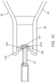
- FIG. 1C shows an exemplary embodiment of a pin 34 that may be carried by the actuator 30 (not shown in FIG. 1C ).
- the pin 34 includes a blunt, e.g., beveled tip 34a that may be sized to open a canister 40.
- a beveled tip 34a may apply a more localized force to a septum 167 of the canister 40 (e.g., the septum 167 shown in FIGS. 5A and 5B and described further elsewhere herein), which may reduce the overall force needed to open the septum 167, as described further elsewhere herein.
- the pin 34 may have a diameter or other cross-section smaller than the septum 167, e.g., to allow gas to flow freely and/or quickly around the pin 34 once the septum 167 is opened, as described elsewhere herein.
- the lens compartment 22 may be a lens cartridge that may be loaded into the lens delivery portion 20. In other instances, the lens compartment 22 may be fixedly attached to or form an integral part of the IOL inserter 10.
- the IOL inserter 10 may be used to deliver a lens contained within the lens compartment 22 into a patient's eye.
- the actuator 30 may be activated to deliver gas from the canister 40 through one or more passages of the main body portion 12, e.g., to pressurize an incompressible fluid to deliver the lens from the lens delivery portion 20 during a cataract surgical procedure.
- the canister 40 may provide a single-use energy source for a medical device or other tool, such as the IOL inserter 10 of FIGS. 1A and 1B .
- the canister 40 includes a body 50 and a cap 60 welded to the body 50 to provide an enclosed cavity 42 filled with a fluid, e.g., carbon dioxide.
- the fluid contained within the enclosed cavity 42 may be used to provide a desired potential energy or discharge force to the IOL inserter 10, e.g., to advance the lens from the lens delivery portion 20.
- the canister 40 may be filled with other two-phase gases, such as a hydrofluorocarbon (e.g., HFC-134a), or a single-phase gas, such as nitrogen.
- a hydrofluorocarbon e.g., HFC-134a
- a single-phase gas such as nitrogen.
- pressurized gas may include a single-phase gas or a two-phase gas, e.g., in which the gas has been at least partially liquefied, and so may include either a gaseous or mixed liquid-gaseous state fluid.
- the volume of the cavity 42 may be sufficient to provide energy to the medical device, e.g., a discharge force for the IOL inserter 10 that may be substantially constant and/or controlled when the actuator 30 is actuated.
- the cavity 42 may have an interior volume of no more than about 1.8 milliliters (1.8 mL), or not more than about one milliliter (1 mL), e.g., between about 0.5-1.8 mL, or between about 0.68-0.75 mL.
- the interior volume of the cavity 42 may be any desired volume.
- the interior volume of the cavity 42 may be greater than 1.8 mL or less than 0.5 mL.
- the body 50 and cap 60 are formed from stainless steel or other corrosion resistant, desired, or suitable metal, or other material.
- one or more of the body 50 and cap 60 may be formed by one or more of drawing, stamping, machining, casting, molding, and the like.
- the body 50 may be deep drawn from sheet metal, e.g., a round sheet metal blank of Type 305 stainless steel, using one or more dies and punches (not shown), e.g., to form a main barrel region 52 and enclosed base or first end 54 of the body 50. Additional processing may be used to form a tapered shoulder region 56 and open neck region or second end 58 defining an opening or passage 59 communicating with an interior 51 of the body 50.
- the shoulder and neck regions 56, 58 may be formed by necking and the like, such that the neck region 58 has a substantially uniform diameter smaller than the diameter of the main barrel region 52.
- the neck region 58 may have a diameter similar to the main barrel region 52, i.e., omitting the shoulder region 56.
- the regions of the body 50 may be substantially radially symmetrical about a central axis 44 of the canister 40.
- the neck region 58 may terminate in a substantially planar end wall 58a defining a plane substantially perpendicular to the axis 44.
- the body 50 may have a length between the first end 54 and the end wall 58a of the neck region 58 that is less than about thirty millimeters (30 mm), the outer diameter of the barrel region 52 may be not more than about ten millimeters (10 mm) or not more than about eight millimeters (8 mm), and the outer diameter of the neck region 58 may be not more than about five millimeters (5 mm), or not more than about four millimeters (4 mm).
- the neck region 58 may have a substantially uniform diameter length between about three to eight millimeters (3-8 mm) or between about four to six millimeters (4-6 mm), e.g., having sufficient length to accommodate the O-ring 36 and carriage 32 sliding along the neck region 58 during actuation of the IOL inserter 10, as described elsewhere herein.
- the provided dimensions and shapes are merely examples.
- the various dimensions of the various aspects of the canister 40 may be selected to be any desired dimension.
- the shapes of the various aspects of the canister may be any desired shape.
- one or more shapes of one or more aspects of the canister may be radially asymmetrical relative to the central axis 44 of the canister 40.
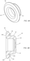
- the cap 60 may be stamped, coined, drawn, and/or otherwise processed from another blank, e.g., to define an annular body 62 having a relatively thin closed or first end 64 and an open second end 66 also symmetrical about the axis 44.
- the annular body 62 may have an outer diameter smaller than the neck region 58 of the body 50 such that the annular body 62 may be inserted into the opening 59 while providing a desired clearance between the annular body 62 and the neck region 58, which facilitates projection welding the cap 60 to the body 50, as described elsewhere herein.
- the closed end 64 is formed to include a penetrable wall or septum 67 having a desired diameter and/or thickness for accessing the gas within the cavity 42 once the canister 40 is loaded into a medical device, as described further elsewhere herein.
- the septum 67 may have a substantially uniform thickness.
- the septum 67 may have a wall thickness between about 0.10-0.25 mm.
- the septum 67 may have a wall thickness of not more than about 0.16 mm.
- the septum 67 may have a diameter between about 0.80-1.20 mm.
- the septum 67 may have a diameter of not more than about 1.0 mm.
- some exemplary dimensions are provided, the scope of the disclosure is not so limited. Rather, the dimensions and shapes of various aspects of the cap 60 may be any desired shape or dimension. For example, the various dimensions and shapes of the cap 60 may be selected based on the application of the cap 60 and/or canister 40.
- the septum 67 may be surrounded by thicker shoulder 68 to support the septum 67 while allowing the septum 67 to be penetrated during operation of a medical device.
- the septum 67 may be penetrated during loading of the canister 40 into a medical device.
- the septum 67 may be penetrated some time after installation of the canister 40 into the medical device, such as, for example, during actuation of the medical device.
- the septum 67 may be sized to engage the pin 34 of the IOL inserter 10 shown in FIG. IB when the canister 40 is loaded into the chamber 16 of the IOL inserter 10 such that the pin 34 easily punctures the septum 67 with a desired maximum puncture force when the actuator 30 is first activated.
- the force needed to puncture the septum 67 may be not more than about one hundred Newtons (100 N).
- the force needed to puncture the septum 67 may be not more than about eighty Newtons (80 N).
- the force needed to puncture the septum 67 may be selected to be any desired force.
- the puncture force may be greater than eighty Newtons (80 N) or greater than one hundred Newtons (100 N).
- the septum 167 may be a generally circular disc or panel defining a first thickness surrounded by a relatively thin- walled perimeter 167b extending to the shoulder 168, e.g. , similar to the septum 167 shown in FIGS. 5 A and 5B described elsewhere herein.
- the thickness of the perimeter 167b may be selected to facilitate separation of the septum 167 at least partially from the shoulder 168 when a predetermined puncture force is applied to the septum 167, e.g., not more than about eighty Newtons (80 N) or otherwise similar to the other embodiments described elsewhere herein.
- the second end 66 of the cap 60 includes an annular flange 69 extending radially outwardly relative to the annular body 62, e.g. , substantially perpendicular to the axis 44, thereby defining a lower surface 69a adjacent the annular body 62 and an upper surface 69b opposite the lower surface 69a.
- the lower surface 69a may be substantially planar and may include an annular projection 70 that is spaced apart from the annular body 62 and from an outer edge 69c of the annular flange 69.
- the projection 70 may extend entirely around the annular body 62 along the lower surface 69a.
- the projection 70 may be continuous. In other embodiments, the projection 70 may be discontinuous.
- the projection 70 may taper from the lower surface 69a and terminate in a substantially planar end surface 70a, e.g. , having a height between about 0.2-0.3 mm, e.g., about 0.25 mm.
- the projection 70 may be omitted and the lower surface 169a of the annular flange 160 may be positioned immediately against the end wall 58a of the neck region 58, as described elsewhere herein.
- the body 50 and cap 60 may be further processed, e.g., deburred, have sharp edges broken, and the like, to provide, for example, a desired finish for the components before assembly.
- the cap 60 may be substantially permanently attached to the body 50, e.g., by projection welding.
- the body 50 and cap 60 may be placed in a filling chamber (not shown) and the filling chamber may be filled with carbon dioxide (or other gas) to a desired pressure, thereby filling the interior 51 of the body 50 with the C02.
- the filling chamber may be controlled to a desired temperature such that it is below the saturation temperature of the gas at filling pressure to condense the gas in the canister 40, thus filling the canister 40 with liquefied gas.
- the cap 60 may be welded to the neck region 58 to close the interior 51 and seal the liquid C02 within the resulting canister 40.
- the first end 64 of the annular body 62 may inserted into the passage 59 in the neck region 58 such that the wall of the annular body 62 is spaced apart from the inner surface of the neck region 58, e.g. , until the end surface 70a of the projection 70 contacts the end wall 58a of the neck region 58.
- the resulting weld may be formed between the projection 70 and the end wall 58a of the neck region 58.
- the body 50 may be coupled to ground (or one electrode) within the filling chamber and an opposite electrode may be placed against the upper surface 69b of the annular flange 69 on the cap 60, thereby holding the projection 70 against the end wall 58a of the neck region 58.
- electrical energy may be applied to the electrode, thereby forming a weld to attach the cap 60 and seal the resulting cavity 42 of the canister 40 with a desired volume of liquid C02 therein.
- the septum may be formed within the same plane as the annular flange 69, which may have an outer diameter that is larger than the neck region 58 of the body 50, and an outer lip or flange may be provided (not shown) around the annular flange 69 sized to be received over the neck region 58.
- the outer lip or flange instead of inserting the annular body of the cap into the open second end, the outer lip or flange may be positioned over the open second end and welded to the neck region 58, e.g., similar to a bottle cap, except including a separable septum, such as any of the embodiments described herein.
- the C02 When the canister 40 is removed from the filling chamber, the C02 may return to its gaseous state or a mixed liquid-gaseous state, thereby providing a desired pressure within the cavity 42.
- the mass of C02 provided within the canister 40 after filling may be about six hundred milligrams (600 mg) or less, or about five hundred milligrams (500 mg) or less and/or having a resulting density between about 0.50-1.0 kg/L or between about 0.50-0.75 kg/L.
- the mass and/or density of the fluid, such as C02, within the canister 40 may be selected to be any desired mass or density.
- gases or fluids other than C02 may be used to fill the canister 40 that provide a desired pressure and/or discharge force during use, as desired.
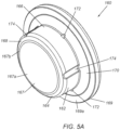
- FIGS. 5A and 5B another embodiment of a cap 160 is shown that may be formed using similar materials and methods as the cap 60, e.g., drawn from a blank to define an annular body 162 having a relatively thin closed or first end 164 and an open second end 166.
- the annular body 162 may have an outer diameter smaller than the neck region 58 of the body 50 such that the annular body 162 may be inserted into the opening 59 while providing a desired clearance between the annular body 162 and the neck region 58, which facilitates projection welding the cap 160 to the body 50, as described elsewhere herein.
- the closed end 164 is formed to include a separable wall or septum 167 having a desired diameter and/or thickness for accessing the gas within the cavity 42 once the canister 40 is loaded into a medical device (not shown), as described further elsewhere herein.
- the septum 167 may include a relatively thicker central region 167a at least partially surrounded by a relatively thin perimeter 167b.
- the perimeter 167b may completely surround the central region 167a or may extend only partially around the central region 167a, e.g., to provide a preferential hinge, as explained further elsewhere herein.
- the central region 167a may have a dome shape, e.g., as best seen in FIG.
- the cap 160 may include a relatively thin- walled septum 167' similar to the cap 60, e.g., as shown in FIG. 6 , or the cap 60 shown in FIGS. 4 A and 4B may include a thin perimeter surrounding a thicker central region (not shown).
- the septum 167 may be surrounded by a relatively thicker shoulder 168 to support the septum 167 while allowing the septum 167 to be at least partially separated from the shoulder 168 during operation of a medical device.
- the septum 167 is configured to be pressed inwardly to cause the perimeter 167b to tear or otherwise separate at least partially between the central region 167a and the shoulder during or after loading of the canister 40 into a medical device, as described elsewhere herein.
- a pin 34 may be provided that includes a beveled tip 34a, which may apply a localized force against one side of the septum 167, which may enhance separation of the septum 167 at least partially from the shoulder 168.
- the pin 34 may have a diameter smaller than the outer perimeter of the septum 167, e.g., to facilitate gas flowing freely from the canister 60 around the pin 34 once the septum 167 is at least partially separated from the shoulder 168.
- the second end 166 of the cap 160 includes an annular flange 169 extending radially outwardly relative to the annular body 162, e.g., substantially perpendicular to the axis 44, thereby defining a lower surface 169a adjacent the annular body 162 and an upper surface 169b opposite the lower surface 169a.
- the lower surface 169a may be substantially planar and may include an annular chamfer 170 that transitions from the lower surface 169a to the second end 166 of the annular body 162, e.g., to provide a welding interface for attaching the cap 160 to the body 50, as described further elsewhere herein.
- the annular body 162 may include one or more radial projections 172, e.g., a plurality of projections 172 spaced apart around the circumference of the second end 166.
- the projections 172 may be sized to contact the inner surface of the neck region 58 immediately adjacent the end wall 58a (shown in FIG. 6 ) to hold the cap 160 stationary and/or centered on the neck region 58 during attachment.
- the annular body 162 may include one or more grooves or passages 174 in the outer surface of the annular body 162, e.g., a plurality of passages 174 extending between the first and second ends 164, 166, which may facilitate gas entering the interior of the canister 40 during filling.
- the first end 164 of the cap 160 may be inserted into the passage 59 in the neck region 58 of the body 50 until the flange 169 contacts the end wall 58a of the neck region 58.
- the projections 172 may hold the cap 160 in place and/or center the cap 160 within the passage 59.
- the body 50 and cap 160 may be placed in a filling chamber (not shown) and the filling chamber may be filled with carbon dioxide (or other gas) to a desired pressure, thereby filling the interior 51 of the body 50 with the CO2.
- the passages 174 may facilitate the gas passing by the cap 160 into the interior 51.
- the cap 160 may be welded to the neck region 58 to close the interior 51 and seal the liquid CO2 within the resulting canister 40.
- the first end 164 of the annular body 162 may inserted into the passage 59 in the neck region 58 such that the wall of the annular body 162 is spaced apart from the inner surface of the neck region 58, e.g., until the lower surface 169a of the flange 169 contacts the end wall 58a of the neck region 58.
- the chamfer 170 may localize the resulting weld to the inner perimeter of the neck region 58, provide line contact to localize weld current to enable a consistent weld, may center the cap 160 in the neck region 58, and/or reduce flaring of the outer neck diameter.
- other features may be provided on the cap 160 to create a concentrated flow of current at desired locations of the cap 160 and/or neck 58 to enhance resistance welding of the cap 160 to the neck 58.
- the canister 40 may be weighed to confirm that a desired amount of gas has been loaded into the canister 40.
- the mass and pressure of the gas may be determined by comparing the mass after filling with the original mass of the body 50 and cap 60, e.g., to confirm that the mass and pressure lie within desired tolerances.
- a desired maximum density e.g. 0.75 mg/mL
- the density and/or mass of the fluid contained within the canister 40 may be any desired density or mass.
- the canister 40 may be weighed again, e.g., at one or more desired intervals, to ensure that the gas has not leaked from the canister 40.
- other methods may be used to confirm that gas remains within the canister 40, e.g., mass spectrometry and the like.
- the canister 40 may be weighed to ensure that an adequate fill of gas remains to ensure sufficient gas through the stroke of the medical device into which the canister 40 is to be loaded.
- One approach is to weigh the canister 40 following filling; expose the canister 40 to elevated temperatures to raise the internal pressure to accelerate any leakage that may be present; reweigh the canister 40 to determine if the mass has been reduced indicating the leak; and then extrapolate the leakage rate over the shelf life to ensure that sufficient gas will remain in the canister 40 over the shelf life of the product.
- Forming the body 50 and cap 60 from stainless steel may provide corrosion protection for the resulting canister 40 over its target shelf life.
- Galvanized steel has been used for conventional gas canisters to provide corrosion protection, but may be inadequate for the canister 40.
- metallic plating e.g., zinc
- the plating cannot be applied before welding the cap 60 to the body 50 since the plating would be lost at the weld, thereby compromising the corrosion protection. If additional plating were applied to the weld, the plating may not have a uniform thickness (on each canister and between different canisters).
- any appropriate and/or desired material such as metal, plastic, and/or composite materials, may be used instead of stainless steel or galvanized steel.
- Such variances in plating may not meet the required tolerances to ensure that the mass and/or pressure of the gas within the finished cylinder falls within the desired range.
- Stainless steel can be formed to higher tolerances since no such plating is needed, thereby ensuring that the properties of the gas may be accurately determined after filling and/or over the shelf life of the canister.
- the canister 40 may be loaded into a medical device to provide an energy source that may be controllably released to provide a desired discharge force to operate the medical device.
- the energy source may be pressurized CO2.
- the IOL inserter 10 may be provided to the user with the canister 40 pre-loaded within the chamber 16 of the housing 12.
- a medical device pre-loaded with the canister 40 may be a disposable, single-use device.
- the cap 14 may be substantially permanently coupled to the housing 12, e.g., by bonding with adhesive, sonic welding, interference fit, one or more connectors, and the like (not shown) to prevent the cap 14 and canister 40 from being removed by the user.
- the IOL inserter 10 may be a reusable device, e.g., in which the user may load one or more canisters 40 successively into the housing 12, as desired.
- the user may remove the cap 14 and load a canister 40 into the chamber 16 of the main body portion 12 of the IOL inserter 10, e.g., such that the septum 67 of the cap 60 is disposed adjacent the pin 34, as shown in FIG. 1 A .
- the cap 14 may then be reconnected to the main body portion 12 to secure the canister 40 within the housing 12.
- the actuator 30 may be activated to direct the carriage 32 proximally to the proximal position shown in FIG. IB such that the pin 34 penetrates the septum 67, thereby delivering C02 from the canister 40 into one or more passages of the IOL inserter 10.
- the perimeter 167b of the septum 167 may tear or otherwise separate at least partially around the central region 167a, thereby delivering C02 from the canister 140.
- the released C02 may be used to pressurize an incompressible liquid, e.g., silicone oil, within the housing 12.
- the pressurized incompressible liquid may be used to deliver a lens from the lens compartment 22.
- the O- ring seal 36 may slide along the neck region 58 and prevent C02 from leaking into the chamber 16 or elsewhere other than the intended passages within the IOL inserter 10. The actuator 30 may then be released, allowing the carriage 32 to return to the distal position shown in FIG. 1 A .
- the lens compartment 22 may loaded into the lens delivery portion 20 (or may already be loaded). However, as explained above, the lens compartment 22 may be fixedly attached to the main body portion 12 or form an integral portion thereof.
- the actuator 30 of the IOL inserter 10 may be activated at any time to controllably deliver the incompressible fluid under constant pressure from the C02, e.g., silicone oil, to deliver the lens from the lens compartment 22.
- the actuator 30 may be selectively actuated such that the flow rate of the incompressible liquid is proportional to the extent the actuator 30 is activated, e.g., to advance the lens from the lens compartment 22 at a controlled speed.
- the entire IOL inserter 10 may be disposed of or, if reusable, the canister 40 may be removed, the medical device may be cleaned and/or otherwise prepared for another procedure, at which time another canister may be loaded into the medical device.
- the gas canisters herein have been described for use with an IOL inserter, it will be appreciated that the gas canisters may be used with other medical devices.
- the gas canisters may be used within a syringe device, such as that disclosed in U.S. Patent Application Publication No. 2013/0317478 .
- a syringe device may include a needle or other cannula that may be used to deliver viscous or other fluids contained within the device into an eye, with the gas canister providing a discharge force that may be controlled by an actuator of the syringe device to controllably deliver the fluid into an eye.
- the gas canisters may be used to deliver a tubular shunt or other implant (not shown) into an eye or other region of a patient's body.
Landscapes
- Health & Medical Sciences (AREA)
- Engineering & Computer Science (AREA)
- Life Sciences & Earth Sciences (AREA)
- Biomedical Technology (AREA)
- Heart & Thoracic Surgery (AREA)
- Animal Behavior & Ethology (AREA)
- General Health & Medical Sciences (AREA)
- Public Health (AREA)
- Veterinary Medicine (AREA)
- Ophthalmology & Optometry (AREA)
- Vascular Medicine (AREA)
- Transplantation (AREA)
- Oral & Maxillofacial Surgery (AREA)
- Cardiology (AREA)
- Mechanical Engineering (AREA)
- Surgery (AREA)
- General Engineering & Computer Science (AREA)
- Nuclear Medicine, Radiotherapy & Molecular Imaging (AREA)
- Medical Informatics (AREA)
- Molecular Biology (AREA)
- Hematology (AREA)
- Anesthesiology (AREA)
- Pathology (AREA)
- Chemical & Material Sciences (AREA)
- Dispersion Chemistry (AREA)
- Prostheses (AREA)
- Filling Or Discharging Of Gas Storage Vessels (AREA)
- External Artificial Organs (AREA)
- Infusion, Injection, And Reservoir Apparatuses (AREA)
- Medical Preparation Storing Or Oral Administration Devices (AREA)
- Gas Separation By Absorption (AREA)
- Acyclic And Carbocyclic Compounds In Medicinal Compositions (AREA)
Description
- The present disclosure relates generally to canisters for storing gases, and, more particularly, to single-use gas canisters that may be loaded into a medical device or other tool for providing energy during use of the medical device or other tool, and to methods for making such canisters.
- Various surgical procedures involve the use of medical devices that require an energy source, e.g., to provide a discharge force to components of the devices. For example, an intraocular lens inserter device may be used to deliver a replacement lens within an eye suffering from a cataract. Such an IOL inserter may require an external power source to push a lens loaded into the inserter into a patient's eye.
- Accordingly, energy sources for IOL inserters and other medical devices or tools would be useful.
-
US 2,685,383 describes a pressure bulb cap welded to the neck of a pressure bulb. The cap includes a relatively thin wall adapted to be pierced by a piercing pin when the bulb is introduced into syphon. -
US 4,416,388 discloses a pressure relief device for a container having a cylindrical side wall which is closed at one end by an internally concave bottom wall. The device comprises an externally protruding first cup formed as an impression in the container bottom wall. The first cup has a first circular wall which is joined at one end to the container bottom wall and which is closed at the opposite end by a first base portion; A tab member is located in the first base portion. The tab member is partially circumscribed by a line of reduced material thickness along which the first base portion is adapted to separate in response to an overpressurization of the container contents, thus freeing the tab member for outward deflection to provide an outlet through which the contents may escape. A second element having a second circular wall is forcibly received within the first circular wall of the first cup. The second circular wall is dimensioned to coact with the first circular wall to radially stress the first base portion in tension. -
US 5,632,505 discloses a pressure vessel that includes a tank containing fluid under pressure, and includes a closure cap for closing the tank. The closure cap is a unitary part made entirely of a homogeneous material. The unitary part includes a rupturable closure wall which, when ruptured, permits fluid to flow outward from the tank. The unitary part also includes a conduit for directing fluid to flow outward from an outlet opening when the closure wall is ruptured. The closure wall has oppositely facing inner and outer side surfaces and includes a stress riser. The side surfaces have contours which direct the fluid pressure to maintain the stress riser under compressive stress and shear stress, rather than tensile stress, so as to resist creep throughout the time that the fluid is contained under pressure in the tank. - The present disclosure is directed to single-use gas canisters that may be loaded into a medical device or other tool for providing energy during use of the medical device or other tool, and to methods for making such canisters.
- According to the claimed invention there is provided a single-use canister and method of making a single-use canister as claimed in the appended claims.
- In accordance with an exemplary embodiment, a single-use canister is provided that includes an elongate, e.g., cylindrical, body and a cap attached to the body to define a cavity filled with gas, e.g., pressurized and/or at least partially liquefied carbon dioxide. The body includes a barrel region defining a first diameter, an enclosed first end, and a neck region, optionally defining a second diameter smaller than the first diameter, and extending from the barrel region to an open second end defining an end wall,
the body defining a central axis extending between the first end and the second end. The cap includes an annular portion including a closed first end an open second end, a penetrable or separable septum formed in the first end, and an annular flange extending radially from the second end of the annular portion, thereby defining a lower surface defining a plane substantially perpendicular to the central axis, and an annular projection extending from the lower surface. - The first end of the annular portion is inserted into the open second end of the body of the canister such that the annular portion is spaced from an interior surface of the neck region and the septum is disposed within the neck region, and the projection may be welded to the end wall of the second end of the body, thereby enclosing the cavity.
- A gas-actuated tool is described that includes a housing comprising a functional portion and an actuator portion including a chamber; a canister within the chamber comprising an elongate body comprising an enclosed first end and an open second end, a cap welded to the open second end of the elongate body and including a septum, thereby defining an interior cavity filled with pressurized gas, the septum comprising a central region and a relatively-thin perimeter at least partially surrounding the central region; and a carriage movable within the housing from the first position, the carriage comprising a pin disposed adjacent the septum, the pin including a blunt, beveled tip. An actuator on the actuator portion is coupled to the carriage such that initial activation of the actuator causes the carriage to move from the first position to a second position such that the beveled tip of the pin applies localized force to the septum to at least partially separate the septum from the cap, thereby releasing pressurized gas from the canister into one or more passages within the housing.
- In accordance with another embodiment, a method is provided for making a single-use canister that includes providing an elongate, e.g., cylindrical, body comprising a barrel region defining a first diameter, an enclosed first end, and a neck region defining a second diameter smaller than the first diameter and extending from the barrel region to an open second end defining an annular end wall, the body defining a central axis extending between the first end and the second end; and providing a cap comprising an annular portion including a closed first end and an open second end, a penetrable or separable septum formed in the first end, and an annular flange extending radially from the second end of the annular portion, thereby defining a lower surface defining a plane substantially perpendicular to the central axis, and an annular projection extending from the lower surface. The first end of the annular portion is inserted into the open second end of the body of the canister such that the annular portion is spaced from an interior surface of the neck region and the septum is disposed within the neck region. Gas, e.g. , carbon dioxide, nitrogen, or hydrofluorocarbon, is introduced into an interior of the body, and the projection is welded to the end wall of the second end of the body, thereby enclosing a cavity of the canister with the gas therein.
- Alternatively, in an unclaimed example, the cap (including a separable septum) may include an outer flange that is larger than the open second end of the body. Instead of inserting the cap into the open second end, the flange may be positioned over the open second end and welded to the neck region.
- In accordance with yet another example, a method is provided for preparing a medical device or other tool for a procedure that includes providing a device comprising a housing including a chamber with a canister therein, an actuator, and a carriage in a first position within the housing, the canister comprising an elongate body comprising an enclosed first end and an open second end, a cap welded to the open second end including a septum, thereby defining an interior cavity filled with pressurized and/or at least partially liquefied gas; and actuating the actuator to cause the carriage to move from the first position to a second position such that a pin on the carriage opens the septum, thereby releasing pressurized gas from the canister into one or more passages within the device. In one embodiment, the septum may be a relatively thin-walled panel that may be penetrated or punctured by the pin to open the cap. According to the claimed invention, the septum includes a relatively thin perimeter surrounding a relatively thick central portion such that, the pin causes at least a portion of the perimeter to tear inwardly to open the cap.
- In accordance with still another example, a method is provided for preparing a medical device or other tool for a procedure that includes providing a canister comprising an elongate body comprising an enclosed first end and an open second end, a cap welded to the open second end including a septum, thereby defining an interior cavity filled with pressurized and/or at least partially liquefied gas; loading the canister into a housing of a device; and actuating the device to cause a pin in the housing to open the septum, thereby releasing pressurized gas from the canister into one or more passages within the device.
- In accordance with another example, a method is provided for performing a procedure that includes providing a medical device comprising a housing including a chamber with a canister therein, an actuator, and a carriage in a first position within the housing, the canister comprising an elongate body comprising an enclosed first end and an open second end, a cap welded to the open second end including a septum, thereby defining an interior cavity filled with pressurized and/or at least partially liquefied gas; initially actuating the actuator to cause the carriage to move from the first position to a second position such that a pin on the carriage opens the septum, thereby releasing pressurized gas from the canister into one or more passages within the medical device to pressurize an incompressible liquid within the housing; and subsequently actuating the actuator, thereby causing the incompressible liquid to flow and deliver one of an agent and an implant from the medical device into a patient.
- In accordance with still another example, a medical device is provided that includes a housing comprising a treatment portion and an actuator portion including a chamber; a canister within the chamber comprising an elongate body comprising an enclosed first end and an open second end, a cap welded to the open second end and including a penetrable or separable septum, thereby defining an interior cavity filled with pressurized gas; a carriage movable within the housing from the first position, the carriage comprising a pin disposed adjacent the septum; and an actuator on the actuator portion coupled to the carriage such that initial activation of the actuator causes the carriage to move from the first position to a second position such that the pin opens the septum, thereby releasing pressurized gas from the canister into one or more passages within the medical device.
- In accordance with yet another example, a gas-powered tool is provided that includes a housing comprising a functional portion and an actuator portion including a chamber; a canister within the chamber comprising an elongate body comprising an enclosed first end and an open second end, a cap welded to the open second end and including a penetrable or separable septum, thereby defining an interior cavity filled with pressurized and/or at least partially liquefied gas; a carriage movable within the housing from the first position, the carriage comprising a pin disposed adjacent the septum; and an actuator on the actuator portion coupled to the carriage such that initial activation of the actuator causes the carriage to move from the first position to a second position such that the pin opens the septum, thereby releasing pressurized gas from the canister into one or more passages within the tool.
- The pin may include a blunt, e.g., beveled, tip that may be sized to open the septum. For example, a beveled tip may apply a more localized force to the septum, which may reduce the overall force needed to open the septum. The pin may have a diameter or other cross-section smaller than the septum, e.g., to allow gas to flow freely and/or quickly around the pin once the septum is opened.
- Other aspects and features including the need for and use of the present disclosure will become apparent from consideration of the following description taken in conjunction with the accompanying drawings.
- It will be appreciated that the exemplary apparatus and components thereof shown in the drawings are not necessarily drawn to scale, with emphasis instead being placed on illustrating the various aspects and features of the illustrated embodiments. The drawings illustrate exemplary embodiments, in which:
-
FIG. 1 A is a cross-sectional view of an exemplary embodiment of an intraocular lens inserter including a single-use gas canister loaded therein. - FIG. IB is a cross-sectional view of the lens inserter of
FIG. 1 A with an actuator activated such that a pin punctures a septum of the gas canister to deliver gas therefrom for providing an energy source for the lens inserter. -
FIG. 1C is a detail showing an exemplary embodiment of a pin on an actuator, such as that shown inFIGS. 1 A and1B , which may be used to puncture the septum of a gas canister. -
FIG. 2 is a cross-sectional view of an example of a gas canister including a cap welded to a body. -
FIG. 3 is a cross-sectional detail of the body of the canister ofFIG. 2 . -
FIGS. 4 A and 4B are perspective and cross-sectional views of the cap of the canister ofFIG. 2 . -
FIGS. 5A and5B are perspective and cross-sectional views of another embodiment of a cap. -
FIG. 6 is a cross-sectional detail showing the cap ofFIGS. 5 A and5B being attached to the neck of a body, such as the body ofFIG. 3 . - Turning to the drawings,
FIGS. 1A and IB show an exemplary embodiment of intraocular lens (IOL)inserter 10 that includes alens delivery portion 20, anactuator 30, and an energy device, e.g.,canister 40. Theintraocular lens inserter 10 may include amain body portion 12, which includes various cavities, recesses, and conduits, e.g., for providing communication between thecanister 40 and thelens delivery portion 20, e.g., for delivering a lens (not shown) from alens compartment 22 loaded into or onto, secured to, or otherwise forming a part of thelens delivery portion 20, e.g., as described inU.S. Publication No. 2015/ 0282928 . Alternatively, theactuator 30 and energy device, e.g.,canister 40, may be provided in other medical devices or tools, which may be actuated by releasing pressurized gas from thecanister 40 to actuate a functional portion of the tool, similar to the methods described elsewhere herein. For example, theactuator 30 andcanister 40 may be provided in a shunt inserter for glaucoma procedures, a syringe plunger pusher for liquid injections, or other tools (not shown). - For example, in the exemplary embodiment shown in
FIGS. 1 A and1B , theIOL inserter 10 may be provided with acanister 40 already provided within thehousing 12, i.e., secured withinchamber 16. Alternatively, thehousing 12 may include aremovable cap 14 allowing thecanister 40 to be removed and replaced with a new canister, if desired. In the embodiment shown, theIOL inserter 10 includes acarriage 32 coupled to theactuator 30 and carrying apin 34. When thecanister 40 is loaded into the chamber 16 (e.g., during manufacturing or before use, such as, for example, where thecanister 40 may be loaded into thehousing 12 via thecap 14 sometime prior to use), thepin 34 may be disposed adjacent aseptum 67 of thecanister 40, as shown inFIG. 1A . In addition, theIOL inserter 10 may include an O-ring orother seal 36 disposed within thechamber 16 adjacent thepin 34, which may slidably engage aneck 58 of thecanister 40, e.g., to provide a substantially fluid-tight seal between theneck 58 and the fluid passages within theIOL inserter 10. - Optionally, the
carriage 32 may be slidably disposed within themain body portion 12, e.g., such that activation of theactuator 30, as shown in FIG. IB, causes thecarriage 32 andpin 34 to move axially, e.g., from the original or distal position shown inFIG. 1 A proximally towards thecanister 40 to the proximal position shown in FIG. IB, thereby puncturing theseptum 67 with thepin 34 and allowing gas to escape from thecanister 40. Optionally, a spring orother biasing mechanism 38 may be provided within themain body portion 12, e.g., within thechamber 16 adjacent the O-ring 36 and/or around theneck 58 of thecanister 40, for biasing thecarriage 32 distally towards the distal position. Thus, when theactuator 30 is released, thecarriage 32 may automatically return to the distal position and thepin 34 may be withdrawn from theseptum 67, as shown inFIG. 1A . - For example,
FIG. 1C shows an exemplary embodiment of apin 34 that may be carried by the actuator 30 (not shown inFIG. 1C ). In this embodiment, thepin 34 includes a blunt, e.g.,beveled tip 34a that may be sized to open acanister 40. For example, abeveled tip 34a may apply a more localized force to aseptum 167 of the canister 40 (e.g., theseptum 167 shown inFIGS. 5A and5B and described further elsewhere herein), which may reduce the overall force needed to open theseptum 167, as described further elsewhere herein. Thepin 34 may have a diameter or other cross-section smaller than theseptum 167, e.g., to allow gas to flow freely and/or quickly around thepin 34 once theseptum 167 is opened, as described elsewhere herein. - In some instances, the
lens compartment 22 may be a lens cartridge that may be loaded into thelens delivery portion 20. In other instances, thelens compartment 22 may be fixedly attached to or form an integral part of theIOL inserter 10. TheIOL inserter 10 may be used to deliver a lens contained within thelens compartment 22 into a patient's eye. For example, theactuator 30 may be activated to deliver gas from thecanister 40 through one or more passages of themain body portion 12, e.g., to pressurize an incompressible fluid to deliver the lens from thelens delivery portion 20 during a cataract surgical procedure. - Turning to
FIG. 2 , an exemplary embodiment of acanister 40 is shown. In some instances, thecanister 40 may provide a single-use energy source for a medical device or other tool, such as theIOL inserter 10 ofFIGS. 1A and1B . Generally, thecanister 40 includes abody 50 and acap 60 welded to thebody 50 to provide anenclosed cavity 42 filled with a fluid, e.g., carbon dioxide. The fluid contained within theenclosed cavity 42 may be used to provide a desired potential energy or discharge force to theIOL inserter 10, e.g., to advance the lens from thelens delivery portion 20. In alternative embodiments, thecanister 40 may be filled with other two-phase gases, such as a hydrofluorocarbon (e.g., HFC-134a), or a single-phase gas, such as nitrogen. As used herein, "pressurized gas" may include a single-phase gas or a two-phase gas, e.g., in which the gas has been at least partially liquefied, and so may include either a gaseous or mixed liquid-gaseous state fluid. The volume of thecavity 42 may be sufficient to provide energy to the medical device, e.g., a discharge force for theIOL inserter 10 that may be substantially constant and/or controlled when theactuator 30 is actuated. In an exemplary embodiment, thecavity 42 may have an interior volume of no more than about 1.8 milliliters (1.8 mL), or not more than about one milliliter (1 mL), e.g., between about 0.5-1.8 mL, or between about 0.68-0.75 mL. However, in other embodiments, the interior volume of thecavity 42 may be any desired volume. For example, in some instances, the interior volume of thecavity 42 may be greater than 1.8 mL or less than 0.5 mL. - In some embodiments, the
body 50 andcap 60 are formed from stainless steel or other corrosion resistant, desired, or suitable metal, or other material. In some embodiments, one or more of thebody 50 andcap 60 may be formed by one or more of drawing, stamping, machining, casting, molding, and the like. For example, with reference toFIG. 3 , thebody 50 may be deep drawn from sheet metal, e.g., a round sheet metal blank of Type 305 stainless steel, using one or more dies and punches (not shown), e.g., to form amain barrel region 52 and enclosed base orfirst end 54 of thebody 50. Additional processing may be used to form atapered shoulder region 56 and open neck region orsecond end 58 defining an opening orpassage 59 communicating with an interior 51 of thebody 50. For example, the shoulder andneck regions neck region 58 has a substantially uniform diameter smaller than the diameter of themain barrel region 52. Alternatively, theneck region 58 may have a diameter similar to themain barrel region 52, i.e., omitting theshoulder region 56. The regions of thebody 50 may be substantially radially symmetrical about acentral axis 44 of thecanister 40. Theneck region 58 may terminate in a substantiallyplanar end wall 58a defining a plane substantially perpendicular to theaxis 44. - In an exemplary embodiment, the
body 50 may have a length between thefirst end 54 and theend wall 58a of theneck region 58 that is less than about thirty millimeters (30 mm), the outer diameter of thebarrel region 52 may be not more than about ten millimeters (10 mm) or not more than about eight millimeters (8 mm), and the outer diameter of theneck region 58 may be not more than about five millimeters (5 mm), or not more than about four millimeters (4 mm). Theneck region 58 may have a substantially uniform diameter length between about three to eight millimeters (3-8 mm) or between about four to six millimeters (4-6 mm), e.g., having sufficient length to accommodate the O-ring 36 andcarriage 32 sliding along theneck region 58 during actuation of theIOL inserter 10, as described elsewhere herein. However, the provided dimensions and shapes are merely examples. Thus, the various dimensions of the various aspects of thecanister 40 may be selected to be any desired dimension. Further, the shapes of the various aspects of the canister may be any desired shape. For example, one or more shapes of one or more aspects of the canister may be radially asymmetrical relative to thecentral axis 44 of thecanister 40. - Similarly, as best seen in
FIGS. 4A and 4B , thecap 60 may be stamped, coined, drawn, and/or otherwise processed from another blank, e.g., to define anannular body 62 having a relatively thin closed orfirst end 64 and an opensecond end 66 also symmetrical about theaxis 44. Theannular body 62 may have an outer diameter smaller than theneck region 58 of thebody 50 such that theannular body 62 may be inserted into theopening 59 while providing a desired clearance between theannular body 62 and theneck region 58, which facilitates projection welding thecap 60 to thebody 50, as described elsewhere herein. - The
closed end 64 is formed to include a penetrable wall orseptum 67 having a desired diameter and/or thickness for accessing the gas within thecavity 42 once thecanister 40 is loaded into a medical device, as described further elsewhere herein. Theseptum 67 may have a substantially uniform thickness. For example, theseptum 67 may have a wall thickness between about 0.10-0.25 mm. Theseptum 67 may have a wall thickness of not more than about 0.16 mm. Theseptum 67 may have a diameter between about 0.80-1.20 mm. Theseptum 67 may have a diameter of not more than about 1.0 mm. Although some exemplary dimensions are provided, the scope of the disclosure is not so limited. Rather, the dimensions and shapes of various aspects of thecap 60 may be any desired shape or dimension. For example, the various dimensions and shapes of thecap 60 may be selected based on the application of thecap 60 and/orcanister 40. - The
septum 67 may be surrounded bythicker shoulder 68 to support theseptum 67 while allowing theseptum 67 to be penetrated during operation of a medical device. For example, theseptum 67 may be penetrated during loading of thecanister 40 into a medical device. Alternatively, theseptum 67 may be penetrated some time after installation of thecanister 40 into the medical device, such as, for example, during actuation of the medical device. For example, theseptum 67 may be sized to engage thepin 34 of theIOL inserter 10 shown in FIG. IB when thecanister 40 is loaded into thechamber 16 of theIOL inserter 10 such that thepin 34 easily punctures theseptum 67 with a desired maximum puncture force when theactuator 30 is first activated. In some examples, the force needed to puncture theseptum 67 may be not more than about one hundred Newtons (100 N). Alternatively, the force needed to puncture theseptum 67 may be not more than about eighty Newtons (80 N). However, the force needed to puncture theseptum 67 may be selected to be any desired force. Thus, the puncture force may be greater than eighty Newtons (80 N) or greater than one hundred Newtons (100 N). Upon puncture of theseptum 67, the gas within thecanister 40 is controllably released during use of theIOL inserter 10, as described elsewhere herein. - Alternatively, as shown in
FIG. 1 C , theseptum 167 may be a generally circular disc or panel defining a first thickness surrounded by a relatively thin-walled perimeter 167b extending to theshoulder 168, e.g. , similar to theseptum 167 shown inFIGS. 5 A and5B described elsewhere herein. The thickness of theperimeter 167b may be selected to facilitate separation of theseptum 167 at least partially from theshoulder 168 when a predetermined puncture force is applied to theseptum 167, e.g., not more than about eighty Newtons (80 N) or otherwise similar to the other embodiments described elsewhere herein. - The
second end 66 of thecap 60 includes anannular flange 69 extending radially outwardly relative to theannular body 62, e.g. , substantially perpendicular to theaxis 44, thereby defining alower surface 69a adjacent theannular body 62 and anupper surface 69b opposite thelower surface 69a. Thelower surface 69a may be substantially planar and may include anannular projection 70 that is spaced apart from theannular body 62 and from anouter edge 69c of theannular flange 69. In some embodiments, theprojection 70 may extend entirely around theannular body 62 along thelower surface 69a. In some embodiments, theprojection 70 may be continuous. In other embodiments, theprojection 70 may be discontinuous. In an exemplary embodiment, theprojection 70 may taper from thelower surface 69a and terminate in a substantiallyplanar end surface 70a, e.g. , having a height between about 0.2-0.3 mm, e.g., about 0.25 mm. Alternatively, as shown inFIG. 6 , theprojection 70 may be omitted and thelower surface 169a of theannular flange 160 may be positioned immediately against theend wall 58a of theneck region 58, as described elsewhere herein. - Once formed, the
body 50 andcap 60 may be further processed, e.g., deburred, have sharp edges broken, and the like, to provide, for example, a desired finish for the components before assembly. - The
cap 60 may be substantially permanently attached to thebody 50, e.g., by projection welding. For example, in an exemplary process, thebody 50 andcap 60 may be placed in a filling chamber (not shown) and the filling chamber may be filled with carbon dioxide (or other gas) to a desired pressure, thereby filling the interior 51 of thebody 50 with the C02. The filling chamber may be controlled to a desired temperature such that it is below the saturation temperature of the gas at filling pressure to condense the gas in thecanister 40, thus filling thecanister 40 with liquefied gas. - Once filled, the
cap 60 may be welded to theneck region 58 to close the interior 51 and seal the liquid C02 within the resultingcanister 40. For example, thefirst end 64 of theannular body 62 may inserted into thepassage 59 in theneck region 58 such that the wall of theannular body 62 is spaced apart from the inner surface of theneck region 58, e.g. , until theend surface 70a of theprojection 70 contacts theend wall 58a of theneck region 58. In this manner, when thecap 60 is welded to thebody 50, the resulting weld may be formed between theprojection 70 and theend wall 58a of theneck region 58. For example, in an exemplary projection welding procedure, thebody 50 may be coupled to ground (or one electrode) within the filling chamber and an opposite electrode may be placed against theupper surface 69b of theannular flange 69 on thecap 60, thereby holding theprojection 70 against theend wall 58a of theneck region 58. Once thebody 50 andcap 60 are engaged, electrical energy may be applied to the electrode, thereby forming a weld to attach thecap 60 and seal the resultingcavity 42 of thecanister 40 with a desired volume of liquid C02 therein. - In another, unclaimed, alternative, instead of the
annular body 62, the septum may be formed within the same plane as theannular flange 69, which may have an outer diameter that is larger than theneck region 58 of thebody 50, and an outer lip or flange may be provided (not shown) around theannular flange 69 sized to be received over theneck region 58. In this alternative, instead of inserting the annular body of the cap into the open second end, the outer lip or flange may be positioned over the open second end and welded to theneck region 58, e.g., similar to a bottle cap, except including a separable septum, such as any of the embodiments described herein. - When the
canister 40 is removed from the filling chamber, the C02 may return to its gaseous state or a mixed liquid-gaseous state, thereby providing a desired pressure within thecavity 42. In an exemplary embodiment, the mass of C02 provided within thecanister 40 after filling may be about six hundred milligrams (600 mg) or less, or about five hundred milligrams (500 mg) or less and/or having a resulting density between about 0.50-1.0 kg/L or between about 0.50-0.75 kg/L. In still other embodiments, the mass and/or density of the fluid, such as C02, within thecanister 40 may be selected to be any desired mass or density. Further, it will be appreciated that gases or fluids other than C02 may be used to fill thecanister 40 that provide a desired pressure and/or discharge force during use, as desired. - Turning to
FIGS. 5A and5B , another embodiment of acap 160 is shown that may be formed using similar materials and methods as thecap 60, e.g., drawn from a blank to define anannular body 162 having a relatively thin closed orfirst end 164 and an opensecond end 166. Theannular body 162 may have an outer diameter smaller than theneck region 58 of thebody 50 such that theannular body 162 may be inserted into theopening 59 while providing a desired clearance between theannular body 162 and theneck region 58, which facilitates projection welding thecap 160 to thebody 50, as described elsewhere herein. - The
closed end 164 is formed to include a separable wall orseptum 167 having a desired diameter and/or thickness for accessing the gas within thecavity 42 once thecanister 40 is loaded into a medical device (not shown), as described further elsewhere herein. For example, as shown inFIGS. 5 A and5B , theseptum 167 may include a relatively thickercentral region 167a at least partially surrounded by a relativelythin perimeter 167b. Optionally, theperimeter 167b may completely surround thecentral region 167a or may extend only partially around thecentral region 167a, e.g., to provide a preferential hinge, as explained further elsewhere herein. Optionally, thecentral region 167a may have a dome shape, e.g., as best seen inFIG. 5B or may have a substantially uniform thickness that is substantially thicker than theperimeter 167b. Alternatively, thecap 160 may include a relatively thin- walled septum 167' similar to thecap 60, e.g., as shown inFIG. 6 , or thecap 60 shown inFIGS. 4 A and 4B may include a thin perimeter surrounding a thicker central region (not shown). - The
septum 167 may be surrounded by a relativelythicker shoulder 168 to support theseptum 167 while allowing theseptum 167 to be at least partially separated from theshoulder 168 during operation of a medical device. Theseptum 167 is configured to be pressed inwardly to cause theperimeter 167b to tear or otherwise separate at least partially between thecentral region 167a and the shoulder during or after loading of thecanister 40 into a medical device, as described elsewhere herein. For example, as shown inFIG. 1 C , apin 34 may be provided that includes abeveled tip 34a, which may apply a localized force against one side of theseptum 167, which may enhance separation of theseptum 167 at least partially from theshoulder 168. Thepin 34 may have a diameter smaller than the outer perimeter of theseptum 167, e.g., to facilitate gas flowing freely from thecanister 60 around thepin 34 once theseptum 167 is at least partially separated from theshoulder 168. - The
second end 166 of thecap 160 includes anannular flange 169 extending radially outwardly relative to theannular body 162, e.g., substantially perpendicular to theaxis 44, thereby defining alower surface 169a adjacent theannular body 162 and anupper surface 169b opposite thelower surface 169a. Thelower surface 169a may be substantially planar and may include anannular chamfer 170 that transitions from thelower surface 169a to thesecond end 166 of theannular body 162, e.g., to provide a welding interface for attaching thecap 160 to thebody 50, as described further elsewhere herein. - Optionally, the
annular body 162 may include one or moreradial projections 172, e.g., a plurality ofprojections 172 spaced apart around the circumference of thesecond end 166. Theprojections 172 may be sized to contact the inner surface of theneck region 58 immediately adjacent theend wall 58a (shown inFIG. 6 ) to hold thecap 160 stationary and/or centered on theneck region 58 during attachment. In addition or alternatively, theannular body 162 may include one or more grooves orpassages 174 in the outer surface of theannular body 162, e.g., a plurality ofpassages 174 extending between the first and second ends 164, 166, which may facilitate gas entering the interior of thecanister 40 during filling. - For example, with additional reference to
FIG. 6 , thefirst end 164 of thecap 160 may be inserted into thepassage 59 in theneck region 58 of thebody 50 until theflange 169 contacts theend wall 58a of theneck region 58. The projections 172 (not shown inFIG. 6 ) may hold thecap 160 in place and/or center thecap 160 within thepassage 59. - Similar to other methods herein, in an exemplary process, the
body 50 andcap 160 may be placed in a filling chamber (not shown) and the filling chamber may be filled with carbon dioxide (or other gas) to a desired pressure, thereby filling the interior 51 of thebody 50 with the CO2. Thepassages 174 may facilitate the gas passing by thecap 160 into the interior 51. - Once filled, the
cap 160 may be welded to theneck region 58 to close the interior 51 and seal the liquid CO2 within the resultingcanister 40. For example, thefirst end 164 of theannular body 162 may inserted into thepassage 59 in theneck region 58 such that the wall of theannular body 162 is spaced apart from the inner surface of theneck region 58, e.g., until thelower surface 169a of theflange 169 contacts theend wall 58a of theneck region 58. Once thebody 50 andcap 160 are engaged, electrical energy may be applied to electrodes (not shown) coupled to thecap 160 andbody 50, thereby forming a weld to attach thecap 160 and seal the resultingcavity 42 of thecanister 40 with a desired volume of liquid CO2 therein. When thecap 160 is welded to thebody 50, thechamfer 170 may localize the resulting weld to the inner perimeter of theneck region 58, provide line contact to localize weld current to enable a consistent weld, may center thecap 160 in theneck region 58, and/or reduce flaring of the outer neck diameter. Optionally, it will be appreciated that other features may be provided on thecap 160 to create a concentrated flow of current at desired locations of thecap 160 and/orneck 58 to enhance resistance welding of thecap 160 to theneck 58. - Optionally, after the
canister 40 is removed from the filling chamber, thecanister 40 may be weighed to confirm that a desired amount of gas has been loaded into thecanister 40. For example, the mass and pressure of the gas may be determined by comparing the mass after filling with the original mass of thebody 50 andcap 60, e.g., to confirm that the mass and pressure lie within desired tolerances. For example, it may be desirable to confirm that the pressure within thecanister 40 does not exceed a desired maximum density (e.g., 0.75 mg/mL), which may otherwise result in thecanister 40 exceeding regulatory standards and/or safe pressures. Again, the density and/or mass of the fluid contained within thecanister 40 may be any desired density or mass. - During subsequent storage of the canister 40 (e.g., during its normal shelf life before being loaded into and used with a medical device), it may be desirable to confirm that gas has not leaked from the
canister 40 during its intended shelf life. For example, thecanister 40 may be weighed again, e.g., at one or more desired intervals, to ensure that the gas has not leaked from thecanister 40. Alternatively, other methods may be used to confirm that gas remains within thecanister 40, e.g., mass spectrometry and the like. For example, despite thecap 60 being welded to thebody 50, gas may still leak from thecanister 40 and, therefore, thecanister 40 may be weighed to ensure that an adequate fill of gas remains to ensure sufficient gas through the stroke of the medical device into which thecanister 40 is to be loaded. One approach is to weigh thecanister 40 following filling; expose thecanister 40 to elevated temperatures to raise the internal pressure to accelerate any leakage that may be present; reweigh thecanister 40 to determine if the mass has been reduced indicating the leak; and then extrapolate the leakage rate over the shelf life to ensure that sufficient gas will remain in thecanister 40 over the shelf life of the product. - Forming the
body 50 andcap 60 from stainless steel may provide corrosion protection for the resultingcanister 40 over its target shelf life. Galvanized steel has been used for conventional gas canisters to provide corrosion protection, but may be inadequate for thecanister 40. In particular, metallic plating, e.g., zinc, cannot be applied before welding thecap 60 to thebody 50 since the plating would be lost at the weld, thereby compromising the corrosion protection. If additional plating were applied to the weld, the plating may not have a uniform thickness (on each canister and between different canisters). However, it will be appreciated that any appropriate and/or desired material, such as metal, plastic, and/or composite materials, may be used instead of stainless steel or galvanized steel. - Such variances in plating (before or after welding) may not meet the required tolerances to ensure that the mass and/or pressure of the gas within the finished cylinder falls within the desired range. Stainless steel can be formed to higher tolerances since no such plating is needed, thereby ensuring that the properties of the gas may be accurately determined after filling and/or over the shelf life of the canister.
- Subsequently, during manufacturing, the
canister 40 may be loaded into a medical device to provide an energy source that may be controllably released to provide a desired discharge force to operate the medical device. As explained above, in some embodiments, the energy source may be pressurized CO2. For example, in some embodiments, theIOL inserter 10 may be provided to the user with thecanister 40 pre-loaded within thechamber 16 of thehousing 12. Thus, in some instances, a medical device pre-loaded with thecanister 40 may be a disposable, single-use device. In some embodiments, thecap 14 may be substantially permanently coupled to thehousing 12, e.g., by bonding with adhesive, sonic welding, interference fit, one or more connectors, and the like (not shown) to prevent thecap 14 andcanister 40 from being removed by the user. - Alternatively, the
IOL inserter 10 may be a reusable device, e.g., in which the user may load one ormore canisters 40 successively into thehousing 12, as desired. For example, with theIOL inserter 10 shown inFIGS. 1A and1B , the user may remove thecap 14 and load acanister 40 into thechamber 16 of themain body portion 12 of theIOL inserter 10, e.g., such that theseptum 67 of thecap 60 is disposed adjacent thepin 34, as shown inFIG. 1 A . Thecap 14 may then be reconnected to themain body portion 12 to secure thecanister 40 within thehousing 12. - At any time, the
actuator 30 may be activated to direct thecarriage 32 proximally to the proximal position shown in FIG. IB such that thepin 34 penetrates theseptum 67, thereby delivering C02 from thecanister 40 into one or more passages of theIOL inserter 10. Alternatively, in the embodiment shown inFIGS. 5A and5B , theperimeter 167b of theseptum 167 may tear or otherwise separate at least partially around thecentral region 167a, thereby delivering C02 from the canister 140. The released C02 may be used to pressurize an incompressible liquid, e.g., silicone oil, within thehousing 12. The pressurized incompressible liquid may be used to deliver a lens from thelens compartment 22. The O-ring seal 36 may slide along theneck region 58 and prevent C02 from leaking into thechamber 16 or elsewhere other than the intended passages within theIOL inserter 10. Theactuator 30 may then be released, allowing thecarriage 32 to return to the distal position shown inFIG. 1 A . - In embodiments in which the
lens compartment 22 defines a separate lens cartridge, thelens compartment 22 may loaded into the lens delivery portion 20 (or may already be loaded). However, as explained above, thelens compartment 22 may be fixedly attached to themain body portion 12 or form an integral portion thereof. Theactuator 30 of theIOL inserter 10 may be activated at any time to controllably deliver the incompressible fluid under constant pressure from the C02, e.g., silicone oil, to deliver the lens from thelens compartment 22. For example, theactuator 30 may be selectively actuated such that the flow rate of the incompressible liquid is proportional to the extent theactuator 30 is activated, e.g., to advance the lens from thelens compartment 22 at a controlled speed. - After the procedure, the
entire IOL inserter 10 may be disposed of or, if reusable, thecanister 40 may be removed, the medical device may be cleaned and/or otherwise prepared for another procedure, at which time another canister may be loaded into the medical device. - Although the gas canisters herein have been described for use with an IOL inserter, it will be appreciated that the gas canisters may be used with other medical devices. For example, the gas canisters may be used within a syringe device, such as that disclosed in
U.S. Patent Application Publication No. 2013/0317478 . For example, such a syringe device may include a needle or other cannula that may be used to deliver viscous or other fluids contained within the device into an eye, with the gas canister providing a discharge force that may be controlled by an actuator of the syringe device to controllably deliver the fluid into an eye. In another embodiment, the gas canisters may be used to deliver a tubular shunt or other implant (not shown) into an eye or other region of a patient's body. - It is fully contemplated that the features, components, and/or steps described with respect to one or more embodiments, methods, or Figures may be combined with the features, components, and/or steps described with respect to other embodiments, methods, or Figures of the present disclosure.
- While the various examples described herein are susceptible to various modifications, and alternative forms, specific examples thereof have been shown in the drawings and are herein described in detail. It should be understood that the scope of the present disclosure is defined by the scope of the appended claims.
Claims (15)
- A single-use canister (40) suitable for loading into a medical device or other tool, comprising:an elongate body (50) comprising a barrel region (52) defining a first diameter, an enclosed first end (54), and a neck region (58) extending from the barrel region to an open second end defining an end wall (58a), the elongate body defining a central axis (44) extending between the first end and the second end; anda cap (160) comprising an annular portion (162) including a closed first end (164) and an open second end (166), a penetrable or separable septum (167) formed in the first end of the cap, and an annular flange (169) extending radially from the second end of the annular portion of the cap, thereby defining a lower surface (169a) defining a plane substantially perpendicular to the central axis, the septum comprising a relatively thicker central region (167a) and a relatively-thin perimeter (167b) at least partially surrounding the central region and configured to tear inwardly to at least partially separate the central region from the cap,the first end of the annular portion of the cap inserted into the open second end of the elongate body such that the annular portion is spaced from an interior surface of the neck region and the septum is disposed within the neck region, the annular flange secured to the end wall of the second end of the elongate body, thereby enclosing a cavity,the cavity filled with pressurized and/or at least partially liquefied gas.
- The canister of claim 1, wherein the septum is surrounded by a relatively thicker shoulder (168) to support the septum while allowing the septum to be at least partially separated from the shoulder.
- The canister of claim 1 or 2, wherein the perimeter (167b) completely surrounds the central region (167a) or extends only partially around the central region (167a).
- The canister of any preceding claim, wherein the lower surface (169a) includes an annular chamfer (170) that transitions from the lower surface (169a) to the second end (166) of the annular portion (162), or other features are provided on the cap (160) to create a concentrated flow of current at desired locations of the cap (160) and/or neck (58) to enhance resistance welding of the cap (160) to the neck (58).
- The canister of any preceding claim, wherein the annular portion (162) includes a plurality of projections (172) spaced apart around the circumference of the second end (166), and wherein the projections (172) are sized to contact the inner surface of the neck region (58) immediately adjacent the end wall (58a) to hold the cap (160) stationary and/or centered on the neck region (58) during attachment.
- The canister of any preceding claim, wherein the annular portion (162) includes one or more grooves or passages (174) in the outer surface of the annular body (162).
- The canister of claim 6, wherein the plurality of passages (174) extend between the first and second ends (164, 166) to facilitate gas entering an interior (51) of the canister (40) during filling.
- The canister of any preceding claim, wherein the elongate body and cap are formed from stainless steel.
- The canister of any preceding claim, wherein the central region has a dome shape.
- A method for making a single-use canister (40) suitable for loading into a medical device or other tool, comprising:providing an elongate body (50) comprising a barrel region (52) defining a first diameter, an enclosed first end (54), and a neck region (58) extending from the barrel region to an open second end defining an end wall (58a), the elongate body defining a central axis (44) extending between the first end and the second end;providing a cap (160) comprising an annular portion (162) including a closed first end (164) and an open second end (166), a penetrable or separable septum (167) formed in the first end of the cap, and an annular flange (169) extending radially from the second end of the annular portion of the cap, thereby defining a lower surface (169a) defining a plane substantially perpendicular to the central axis, the septum comprising a relatively thicker central region (167a) and a relatively-thin perimeter (167b) at least partially surrounding the central region and configured to tear inwardly to at least partially separate the central region from the cap;inserting the first end of the annular portion of the cap into the open second end of the elongate body such that the annular portion of the cap is spaced from an interior surface of the neck region of the elongate body and the septum is disposed within the neck region of the elongate body;introducing pressurized gas into an interior (51) of the elongate body;contacting the lower surface (169a) of the annular flange (169) to the end wall of the second end of the elongate body; andwelding the cap to the neck region, thereby enclosing a cavity of the canister with the pressurized gas therein.
- The method of claim 10, wherein the cavity of the canister has a volume of not more than about 1.8 milliliters (1.8 mL).
- The method of claim 10 or 11, wherein introducing pressurized gas into the interior of the elongate body comprises:providing the cylindrical body and cap within a filling chamber;introducing gas into the filling chamber; andcontrolling the filling chamber temperature to a temperature below the saturation temperature of the gas at the filling pressure to condense the gas within the interior of the elongate body.
- The method of any one of claims 10-12, wherein the elongate body is formed by:deep drawing a round blank of stainless steel to form the barrel region, the first end of the elongate body, and an extension opposite the first end; andnecking down the extension to define the neck region, and/or, optionally,wherein the cap is formed by drawing a round blank of stainless steel, and/or, further optionallywherein the cap is formed by drawing a round blank of stainless steel to form the first end of the cap and the annular flange.
- The method of any one of claims 10-13, further comprising weighing the canister to determine at least one of the mass and the density of the pressurized gas enclosed within the cavity.
- The method of claim 14, further comprising, during a shelf life of the canister, weighing the canister to confirm that a minimum amount of pressurized gas remains enclosed within the cavity.
Priority Applications (1)
| Application Number | Priority Date | Filing Date | Title |
|---|---|---|---|
| EP24206987.0A EP4470934B1 (en) | 2016-03-08 | 2017-03-08 | Gas canisters and methods for making them |
Applications Claiming Priority (2)
| Application Number | Priority Date | Filing Date | Title |
|---|---|---|---|
| US15/064,464 US10610351B2 (en) | 2016-03-08 | 2016-03-08 | Gas canisters and methods for making them |
| PCT/US2017/021446 WO2017156186A2 (en) | 2016-03-08 | 2017-03-08 | Gas canisters and methods for making them |
Related Child Applications (1)
| Application Number | Title | Priority Date | Filing Date |
|---|---|---|---|
| EP24206987.0A Division EP4470934B1 (en) | 2016-03-08 | 2017-03-08 | Gas canisters and methods for making them |
Publications (2)
| Publication Number | Publication Date |
|---|---|
| EP3426567A2 EP3426567A2 (en) | 2019-01-16 |
| EP3426567B1 true EP3426567B1 (en) | 2024-10-23 |
Family
ID=58537060
Family Applications (2)
| Application Number | Title | Priority Date | Filing Date |
|---|---|---|---|
| EP24206987.0A Active EP4470934B1 (en) | 2016-03-08 | 2017-03-08 | Gas canisters and methods for making them |
| EP17717015.6A Active EP3426567B1 (en) | 2016-03-08 | 2017-03-08 | Gas canisters and methods for making them |
Family Applications Before (1)
| Application Number | Title | Priority Date | Filing Date |
|---|---|---|---|
| EP24206987.0A Active EP4470934B1 (en) | 2016-03-08 | 2017-03-08 | Gas canisters and methods for making them |
Country Status (12)
| Country | Link |
|---|---|
| US (1) | US10610351B2 (en) |
| EP (2) | EP4470934B1 (en) |
| JP (1) | JP6923947B2 (en) |
| KR (1) | KR102403294B1 (en) |
| CN (1) | CN109071071B (en) |
| ES (2) | ES3064811T3 (en) |
| IL (1) | IL261703B (en) |
| MX (1) | MX2018010887A (en) |
| RU (1) | RU2748403C2 (en) |
| SG (1) | SG11201807761VA (en) |
| WO (1) | WO2017156186A2 (en) |
| ZA (1) | ZA201806403B (en) |
Families Citing this family (23)
| Publication number | Priority date | Publication date | Assignee | Title |
|---|---|---|---|---|
| EP3799776B1 (en) | 2014-09-25 | 2025-11-26 | BT Bidco, Inc. | Electromechanical pill device with localization capabilities |
| JP7022693B2 (en) * | 2015-11-24 | 2022-02-18 | アクティバックス,インク. | Pressure cartridge and actuation mechanism |
| EP3932453B1 (en) | 2016-04-29 | 2025-11-05 | Altaviz LLC | Self-powered syringe |
| EP4467182A3 (en) | 2016-09-09 | 2025-01-15 | Biora Therapeutics, Inc. | Electromechanical ingestible device for delivery of a dispensable substance |
| EP3551034A1 (en) | 2016-12-07 | 2019-10-16 | Progenity, Inc. | Gastrointestinal tract detection methods, devices and systems |
| IL268900B2 (en) | 2017-03-31 | 2023-11-01 | Biora Therapeutics Inc | Ingestion device placement systems and methods |
| US11890453B2 (en) * | 2017-11-04 | 2024-02-06 | Altaviz, Llc | Injection devices and methods for making and using them |
| WO2019090193A1 (en) | 2017-11-04 | 2019-05-09 | Altaviz, Llc | Injection devices and methods for making and using them |
| WO2019117984A2 (en) * | 2017-12-14 | 2019-06-20 | Axon Enterprise, Inc. | Systems and methods for an electrode for a conducted electrical weapon |
| WO2020106757A1 (en) | 2018-11-19 | 2020-05-28 | Progenity, Inc. | Ingestible device for delivery of therapeutic agent to the gastrointestinal tract |
| US11738154B2 (en) | 2019-09-11 | 2023-08-29 | Altaviz, Llc | Micro-volume injectors with dose guidance and methods for use |
| CN121197633A (en) | 2019-12-13 | 2025-12-26 | 比特比德科有限责任公司 | Ingestible device for delivering therapeutic agents to the gastrointestinal tract |
| FR3106190B1 (en) * | 2020-01-13 | 2023-11-10 | Gaztransport Et Technigaz | Double access hatch for a liquefied gas transport tank |
| EP4271447A1 (en) | 2020-12-31 | 2023-11-08 | Regeneron Pharmaceuticals, Inc. | Auto-injector and related methods of use |
| JP2024525729A (en) | 2021-07-12 | 2024-07-12 | アルタヴィズ,リミティッド・ライアビリティ・カンパニー | Devices, systems and methods for delivering gases - Patents.com |
| KR20240047985A (en) | 2021-07-27 | 2024-04-12 | 액손 엔터프라이즈 인코포레이티드 | Cartridges and electrodes for conductive electric weapons |
| CN113669402A (en) * | 2021-08-19 | 2021-11-19 | 东莞市致力气弹簧有限公司 | Method for plugging gas charging hole after gas spring is charged with nitrogen |
| JP2024535597A (en) | 2021-10-14 | 2024-09-30 | アルタヴィズ,リミティッド・ライアビリティ・カンパニー | DRIVE MODULE FOR AN INJECTOR AND SYSTEM AND METHOD USING SUCH DRIVE MODULE - Patent application |
| EP4212106B1 (en) | 2022-01-13 | 2025-11-12 | Cuantum Medical Cosmetics, S.L. | Handheld device for applying a cyanoacrylate adhesive composition |
| KR20250054067A (en) | 2022-07-28 | 2025-04-22 | 액손 엔터프라이즈 인코포레이티드 | Electrodes for conductive electric weapons |
| CR20250293A (en) | 2022-12-22 | 2025-09-18 | Halozyme Inc | Hyaluronidase enzyme formulations for high volume administration |
| WO2024263656A1 (en) * | 2023-06-19 | 2024-12-26 | Altaviz, Llc | Gas canisters, caps for gas canisters, and methods for making them |
| EP4653751A1 (en) * | 2024-05-16 | 2025-11-26 | Banza Stamping Industry Corp | Pressurized gas vessel and piercing mechanism |
Citations (6)
| Publication number | Priority date | Publication date | Assignee | Title |
|---|---|---|---|---|
| GB191008433A (en) * | 1910-04-07 | 1910-10-27 | Robert Hunter Campbell | Improvements in Containers, or Capsules, for Compressed, or Liquified, Gas. |
| US4293078A (en) * | 1979-11-01 | 1981-10-06 | Becton, Dickinson And Company | Vacuum indicator closure for a blood collection tube |
| US4416388A (en) * | 1982-09-20 | 1983-11-22 | Sexton Can Company, Inc. | Pressure relief device |
| US4976894A (en) * | 1989-09-22 | 1990-12-11 | Nsa Acquisition, Inc. | Carbon dioxide injection interface in carbonation apparatus |
| US5632505A (en) * | 1995-06-29 | 1997-05-27 | Trw Vehicle Safety Systems Inc. | Pressure vessel with rupturable closure wall |
| US20130333796A1 (en) * | 2012-06-13 | 2013-12-19 | Daniel Py | Device with penetrable septum, filling needle and penetrable closure, and related method |
Family Cites Families (35)
| Publication number | Priority date | Publication date | Assignee | Title |
|---|---|---|---|---|
| GB525714A (en) | 1938-03-01 | 1940-09-03 | Walter Kidde Sales Company | Improvements in closures for containers for high pressure fluids |
| US2605763A (en) * | 1948-01-31 | 1952-08-05 | Becton Dickinson Co | Injection device |
| US2547099A (en) * | 1948-03-11 | 1951-04-03 | Becton Dickinson Co | Injection device and ampoule |
| US2613849A (en) * | 1949-06-03 | 1952-10-14 | Prel Inc | Cartridge for pressure dispensing devices |
| US2685383A (en) * | 1952-09-20 | 1954-08-03 | Knapp Monarch Co | Pressure bulb cap |
| US3156369A (en) * | 1962-09-19 | 1964-11-10 | Ethicon Inc | Bicameral container |
| US3688765A (en) * | 1969-10-03 | 1972-09-05 | Jack S Gasaway | Hypodermic injection device |
| BE846754A (en) | 1976-09-30 | 1977-01-17 | DRILLING AND SEALING DEVICE FOR CARBON GAS AND SIMILAR CARTRIDGES | |
| SU1310146A1 (en) * | 1986-02-06 | 1987-05-15 | Ростовский-На-Дону Институт Сельскохозяйственного Машиностроения | Method of gas-shielded two-arc welding |
| JPH01104261A (en) * | 1987-10-16 | 1989-04-21 | Morishita Seiyaku Kk | Opening instrument of liquid container |
| US5029730A (en) * | 1989-03-23 | 1991-07-09 | Sparklet Devices, Inc. | Weldably sealed oxygen container |
| US4954149A (en) | 1989-10-25 | 1990-09-04 | Merlin Instrument Company | Injection septum |
| IT1292677B1 (en) * | 1997-02-28 | 1999-02-11 | Bormioli Metalplast Spa | PACKAGING TO KEEP THE PRODUCTS SEPARATE BEFORE USE. |
| US5957898A (en) * | 1997-05-20 | 1999-09-28 | Baxter International Inc. | Needleless connector |
| JP3414210B2 (en) * | 1997-08-07 | 2003-06-09 | タイガー魔法瓶株式会社 | Manufacturing method of metal vacuum double container |
| WO2001070309A1 (en) | 2000-03-23 | 2001-09-27 | Antares Pharma, Inc. | Single use disposable jet injector |
| JP4737363B2 (en) | 2002-03-29 | 2011-07-27 | アルザ・コーポレーシヨン | Compressed gas cylinder |
| US20080078769A1 (en) * | 2003-09-25 | 2008-04-03 | Crunkleton James T Iii | High pressure gas supply system for a beverage dispensing system |
| US8215481B1 (en) * | 2004-02-18 | 2012-07-10 | Knickerbocker Michael G | Container closure for retaining an additive material |
| PL1642862T3 (en) | 2004-09-29 | 2008-08-29 | Kurt Oberhofer | Container with pressurized CO2-gas source |
| US7857167B1 (en) * | 2005-08-29 | 2010-12-28 | Anthony Scott Hollars | Compressed gas cartridge permeation dispenser having a predictable permeation rate |
| CN2844639Y (en) * | 2005-10-22 | 2006-12-06 | 李健 | High-pressure gas cylinder |
| ATE412559T1 (en) | 2005-12-20 | 2008-11-15 | Key Safety Systems Inc | GAS GENERATOR WITH IMPROVED CAP |
| US9651197B2 (en) | 2006-11-27 | 2017-05-16 | Frank Levy | Disposable cartridge for holding compressed medical gas |
| CN201373236Y (en) * | 2009-03-13 | 2009-12-30 | 上海邦耐机电设备有限公司 | Disposable mini type gas steel cylinder |
| EP2854727B1 (en) | 2012-05-24 | 2019-04-10 | Altaviz LLC | Viscous fluid injector |
| PT2854708T (en) * | 2012-06-04 | 2017-01-17 | Alcon Pharmaceuticals Ltd | Intraocular lens inserter and method for discharging an intraocular lens from a cartridge |
| CA2938374A1 (en) * | 2014-02-04 | 2015-08-13 | Strauss Water Ltd. | Pressurized gas container and coupling means for appliances |
| US20150329341A1 (en) | 2014-02-04 | 2015-11-19 | Strauss Water Ltd. | Pressurized Gas Container |
| WO2015154049A1 (en) | 2014-04-04 | 2015-10-08 | Altaviz, Llc | Intraocular lens inserter |
| CN106572904B (en) * | 2014-07-15 | 2019-06-18 | 爱尔康制药有限公司 | Intraocular lens inserter with temperature compensation |
| US9518703B2 (en) * | 2014-07-24 | 2016-12-13 | Jeffrey James Quail | Disposable compressed gas cartridge with integral sealing member |
| CN204387668U (en) * | 2014-12-10 | 2015-06-10 | 中山市创比诺金属制品有限公司 | High-pressure metal gas cylinder |
| US9738245B1 (en) * | 2015-03-11 | 2017-08-22 | Tk Holdings Inc. | Gas generator with improved supported burst cup |
| US10172706B2 (en) * | 2015-10-31 | 2019-01-08 | Novartis Ag | Intraocular lens inserter |
-
2016
- 2016-03-08 US US15/064,464 patent/US10610351B2/en active Active
-
2017
- 2017-03-08 ES ES24206987T patent/ES3064811T3/en active Active
- 2017-03-08 EP EP24206987.0A patent/EP4470934B1/en active Active
- 2017-03-08 KR KR1020187029046A patent/KR102403294B1/en active Active
- 2017-03-08 SG SG11201807761VA patent/SG11201807761VA/en unknown
- 2017-03-08 WO PCT/US2017/021446 patent/WO2017156186A2/en not_active Ceased
- 2017-03-08 CN CN201780025204.2A patent/CN109071071B/en active Active
- 2017-03-08 ES ES17717015T patent/ES3006758T3/en active Active
- 2017-03-08 MX MX2018010887A patent/MX2018010887A/en unknown
- 2017-03-08 EP EP17717015.6A patent/EP3426567B1/en active Active
- 2017-03-08 IL IL261703A patent/IL261703B/en unknown
- 2017-03-08 JP JP2018567009A patent/JP6923947B2/en active Active
- 2017-03-08 RU RU2018134122A patent/RU2748403C2/en active
-
2018
- 2018-09-26 ZA ZA2018/06403A patent/ZA201806403B/en unknown
Patent Citations (6)
| Publication number | Priority date | Publication date | Assignee | Title |
|---|---|---|---|---|
| GB191008433A (en) * | 1910-04-07 | 1910-10-27 | Robert Hunter Campbell | Improvements in Containers, or Capsules, for Compressed, or Liquified, Gas. |
| US4293078A (en) * | 1979-11-01 | 1981-10-06 | Becton, Dickinson And Company | Vacuum indicator closure for a blood collection tube |
| US4416388A (en) * | 1982-09-20 | 1983-11-22 | Sexton Can Company, Inc. | Pressure relief device |
| US4976894A (en) * | 1989-09-22 | 1990-12-11 | Nsa Acquisition, Inc. | Carbon dioxide injection interface in carbonation apparatus |
| US5632505A (en) * | 1995-06-29 | 1997-05-27 | Trw Vehicle Safety Systems Inc. | Pressure vessel with rupturable closure wall |
| US20130333796A1 (en) * | 2012-06-13 | 2013-12-19 | Daniel Py | Device with penetrable septum, filling needle and penetrable closure, and related method |
Also Published As
| Publication number | Publication date |
|---|---|
| SG11201807761VA (en) | 2018-10-30 |
| EP4470934A1 (en) | 2024-12-04 |
| ES3006758T3 (en) | 2025-03-18 |
| CA3017183A1 (en) | 2017-09-14 |
| IL261703A (en) | 2018-10-31 |
| EP4470934B1 (en) | 2026-01-14 |
| MX2018010887A (en) | 2019-05-20 |
| KR20190008523A (en) | 2019-01-24 |
| RU2018134122A3 (en) | 2021-02-11 |
| JP6923947B2 (en) | 2021-08-25 |
| IL261703B (en) | 2022-08-01 |
| BR112018068240A2 (en) | 2019-01-15 |
| ZA201806403B (en) | 2019-06-26 |
| US10610351B2 (en) | 2020-04-07 |
| CN109071071B (en) | 2021-03-16 |
| US20170258583A1 (en) | 2017-09-14 |
| ES3064811T3 (en) | 2026-04-29 |
| EP3426567A2 (en) | 2019-01-16 |
| CN109071071A (en) | 2018-12-21 |
| RU2018134122A (en) | 2020-04-08 |
| KR102403294B1 (en) | 2022-05-30 |
| WO2017156186A3 (en) | 2018-02-08 |
| WO2017156186A2 (en) | 2017-09-14 |
| JP2019509870A (en) | 2019-04-11 |
| RU2748403C2 (en) | 2021-05-25 |
Similar Documents
| Publication | Publication Date | Title |
|---|---|---|
| EP4470934B1 (en) | Gas canisters and methods for making them | |
| US12516778B2 (en) | Gas canisters and methods for making them | |
| JP2019509870A5 (en) | ||
| RU2174017C2 (en) | System for performing subcutaneous injections | |
| US7645267B2 (en) | Prefilled syringe | |
| US3419007A (en) | Ampoule for use with a needleless hypodermic injector | |
| KR20020087051A (en) | Needleless syringe for injecting a liquid contained a prefilled ampule | |
| CA3017183C (en) | Gas canisters and methods for making them | |
| HK40001863B (en) | Gas canisters and methods for making them | |
| HK40001863A (en) | Gas canisters and methods for making them | |
| US20080140019A1 (en) | Novel Device | |
| BR112018068240B1 (en) | GAS CYLINDERS AND METHODS FOR MANUFACTURING THEM | |
| US20240417233A1 (en) | Gas canisters, caps for gas canisters, and methods for making them | |
| US11305065B2 (en) | Injector | |
| WO2025208126A1 (en) | Gas canisters, caps for gas canisters, and methods for making them | |
| WO2019074505A1 (en) | Paint dispensing method and apparatus | |
| GB2399634A (en) | Fluid storage device | |
| AU3512601A (en) | Hypodermic injection system | |
| AU7939501A (en) | Hypodermic injection systems |
Legal Events
| Date | Code | Title | Description |
|---|---|---|---|
| STAA | Information on the status of an ep patent application or granted ep patent |
Free format text: STATUS: UNKNOWN |
|
| STAA | Information on the status of an ep patent application or granted ep patent |
Free format text: STATUS: THE INTERNATIONAL PUBLICATION HAS BEEN MADE |
|
| PUAI | Public reference made under article 153(3) epc to a published international application that has entered the european phase |
Free format text: ORIGINAL CODE: 0009012 |
|
| STAA | Information on the status of an ep patent application or granted ep patent |
Free format text: STATUS: REQUEST FOR EXAMINATION WAS MADE |
|
| 17P | Request for examination filed |
Effective date: 20181003 |
|
| AK | Designated contracting states |
Kind code of ref document: A2 Designated state(s): AL AT BE BG CH CY CZ DE DK EE ES FI FR GB GR HR HU IE IS IT LI LT LU LV MC MK MT NL NO PL PT RO RS SE SI SK SM TR |
|
| AX | Request for extension of the european patent |
Extension state: BA ME |
|
| DAV | Request for validation of the european patent (deleted) | ||
| DAX | Request for extension of the european patent (deleted) | ||
| STAA | Information on the status of an ep patent application or granted ep patent |
Free format text: STATUS: EXAMINATION IS IN PROGRESS |
|
| 17Q | First examination report despatched |
Effective date: 20211007 |
|
| P01 | Opt-out of the competence of the unified patent court (upc) registered |
Effective date: 20230524 |
|
| REG | Reference to a national code |
Ref country code: DE Ref legal event code: R079 Free format text: PREVIOUS MAIN CLASS: B65D0041200000 Ipc: A61M0005200000 Ref document number: 602017085643 Country of ref document: DE |
|
| GRAP | Despatch of communication of intention to grant a patent |
Free format text: ORIGINAL CODE: EPIDOSNIGR1 |
|
| STAA | Information on the status of an ep patent application or granted ep patent |
Free format text: STATUS: GRANT OF PATENT IS INTENDED |
|
| RIC1 | Information provided on ipc code assigned before grant |
Ipc: A61B 17/00 20060101ALN20240425BHEP Ipc: A61M 11/02 20060101ALN20240425BHEP Ipc: B65B 31/00 20060101ALN20240425BHEP Ipc: F17C 1/00 20060101ALI20240425BHEP Ipc: A61F 2/16 20060101ALI20240425BHEP Ipc: A61F 2/14 20060101ALI20240425BHEP Ipc: A61M 5/20 20060101AFI20240425BHEP |
|
| INTG | Intention to grant announced |
Effective date: 20240514 |
|
| GRAS | Grant fee paid |
Free format text: ORIGINAL CODE: EPIDOSNIGR3 |
|
| GRAA | (expected) grant |
Free format text: ORIGINAL CODE: 0009210 |
|
| STAA | Information on the status of an ep patent application or granted ep patent |
Free format text: STATUS: THE PATENT HAS BEEN GRANTED |
|
| AK | Designated contracting states |
Kind code of ref document: B1 Designated state(s): AL AT BE BG CH CY CZ DE DK EE ES FI FR GB GR HR HU IE IS IT LI LT LU LV MC MK MT NL NO PL PT RO RS SE SI SK SM TR |
|
| REG | Reference to a national code |
Ref country code: GB Ref legal event code: FG4D |
|
| REG | Reference to a national code |
Ref country code: CH Ref legal event code: EP |
|
| REG | Reference to a national code |
Ref country code: DE Ref legal event code: R096 Ref document number: 602017085643 Country of ref document: DE |
|
| REG | Reference to a national code |
Ref country code: IE Ref legal event code: FG4D |
|
| REG | Reference to a national code |
Ref country code: LT Ref legal event code: MG9D |
|
| REG | Reference to a national code |
Ref country code: NL Ref legal event code: MP Effective date: 20241023 |
|
| REG | Reference to a national code |
Ref country code: AT Ref legal event code: MK05 Ref document number: 1734316 Country of ref document: AT Kind code of ref document: T Effective date: 20241023 |
|
| PG25 | Lapsed in a contracting state [announced via postgrant information from national office to epo] |
Ref country code: NL Free format text: LAPSE BECAUSE OF FAILURE TO SUBMIT A TRANSLATION OF THE DESCRIPTION OR TO PAY THE FEE WITHIN THE PRESCRIBED TIME-LIMIT Effective date: 20241023 |
|
| REG | Reference to a national code |
Ref country code: ES Ref legal event code: FG2A Ref document number: 3006758 Country of ref document: ES Kind code of ref document: T3 Effective date: 20250318 |
|
| PG25 | Lapsed in a contracting state [announced via postgrant information from national office to epo] |
Ref country code: NL Free format text: LAPSE BECAUSE OF FAILURE TO SUBMIT A TRANSLATION OF THE DESCRIPTION OR TO PAY THE FEE WITHIN THE PRESCRIBED TIME-LIMIT Effective date: 20241023 |
|
| PG25 | Lapsed in a contracting state [announced via postgrant information from national office to epo] |
Ref country code: IS Free format text: LAPSE BECAUSE OF FAILURE TO SUBMIT A TRANSLATION OF THE DESCRIPTION OR TO PAY THE FEE WITHIN THE PRESCRIBED TIME-LIMIT Effective date: 20250223 Ref country code: PT Free format text: LAPSE BECAUSE OF FAILURE TO SUBMIT A TRANSLATION OF THE DESCRIPTION OR TO PAY THE FEE WITHIN THE PRESCRIBED TIME-LIMIT Effective date: 20250224 Ref country code: HR Free format text: LAPSE BECAUSE OF FAILURE TO SUBMIT A TRANSLATION OF THE DESCRIPTION OR TO PAY THE FEE WITHIN THE PRESCRIBED TIME-LIMIT Effective date: 20241023 |
|
| PG25 | Lapsed in a contracting state [announced via postgrant information from national office to epo] |
Ref country code: FI Free format text: LAPSE BECAUSE OF FAILURE TO SUBMIT A TRANSLATION OF THE DESCRIPTION OR TO PAY THE FEE WITHIN THE PRESCRIBED TIME-LIMIT Effective date: 20241023 |
|
| PG25 | Lapsed in a contracting state [announced via postgrant information from national office to epo] |
Ref country code: BG Free format text: LAPSE BECAUSE OF FAILURE TO SUBMIT A TRANSLATION OF THE DESCRIPTION OR TO PAY THE FEE WITHIN THE PRESCRIBED TIME-LIMIT Effective date: 20241023 |
|
| PG25 | Lapsed in a contracting state [announced via postgrant information from national office to epo] |
Ref country code: NO Free format text: LAPSE BECAUSE OF FAILURE TO SUBMIT A TRANSLATION OF THE DESCRIPTION OR TO PAY THE FEE WITHIN THE PRESCRIBED TIME-LIMIT Effective date: 20250123 |
|
| PG25 | Lapsed in a contracting state [announced via postgrant information from national office to epo] |
Ref country code: LV Free format text: LAPSE BECAUSE OF FAILURE TO SUBMIT A TRANSLATION OF THE DESCRIPTION OR TO PAY THE FEE WITHIN THE PRESCRIBED TIME-LIMIT Effective date: 20241023 Ref country code: GR Free format text: LAPSE BECAUSE OF FAILURE TO SUBMIT A TRANSLATION OF THE DESCRIPTION OR TO PAY THE FEE WITHIN THE PRESCRIBED TIME-LIMIT Effective date: 20250124 Ref country code: AT Free format text: LAPSE BECAUSE OF FAILURE TO SUBMIT A TRANSLATION OF THE DESCRIPTION OR TO PAY THE FEE WITHIN THE PRESCRIBED TIME-LIMIT Effective date: 20241023 |
|
| PG25 | Lapsed in a contracting state [announced via postgrant information from national office to epo] |
Ref country code: PL Free format text: LAPSE BECAUSE OF FAILURE TO SUBMIT A TRANSLATION OF THE DESCRIPTION OR TO PAY THE FEE WITHIN THE PRESCRIBED TIME-LIMIT Effective date: 20241023 |
|
| PG25 | Lapsed in a contracting state [announced via postgrant information from national office to epo] |
Ref country code: RS Free format text: LAPSE BECAUSE OF FAILURE TO SUBMIT A TRANSLATION OF THE DESCRIPTION OR TO PAY THE FEE WITHIN THE PRESCRIBED TIME-LIMIT Effective date: 20250123 |
|
| PG25 | Lapsed in a contracting state [announced via postgrant information from national office to epo] |
Ref country code: SM Free format text: LAPSE BECAUSE OF FAILURE TO SUBMIT A TRANSLATION OF THE DESCRIPTION OR TO PAY THE FEE WITHIN THE PRESCRIBED TIME-LIMIT Effective date: 20241023 |
|
| PG25 | Lapsed in a contracting state [announced via postgrant information from national office to epo] |
Ref country code: DK Free format text: LAPSE BECAUSE OF FAILURE TO SUBMIT A TRANSLATION OF THE DESCRIPTION OR TO PAY THE FEE WITHIN THE PRESCRIBED TIME-LIMIT Effective date: 20241023 |
|
| PGFP | Annual fee paid to national office [announced via postgrant information from national office to epo] |
Ref country code: ES Payment date: 20250403 Year of fee payment: 9 |
|
| PG25 | Lapsed in a contracting state [announced via postgrant information from national office to epo] |
Ref country code: EE Free format text: LAPSE BECAUSE OF FAILURE TO SUBMIT A TRANSLATION OF THE DESCRIPTION OR TO PAY THE FEE WITHIN THE PRESCRIBED TIME-LIMIT Effective date: 20241023 |
|
| PG25 | Lapsed in a contracting state [announced via postgrant information from national office to epo] |
Ref country code: RO Free format text: LAPSE BECAUSE OF FAILURE TO SUBMIT A TRANSLATION OF THE DESCRIPTION OR TO PAY THE FEE WITHIN THE PRESCRIBED TIME-LIMIT Effective date: 20241023 |
|
| REG | Reference to a national code |
Ref country code: DE Ref legal event code: R097 Ref document number: 602017085643 Country of ref document: DE |
|
| PG25 | Lapsed in a contracting state [announced via postgrant information from national office to epo] |
Ref country code: SK Free format text: LAPSE BECAUSE OF FAILURE TO SUBMIT A TRANSLATION OF THE DESCRIPTION OR TO PAY THE FEE WITHIN THE PRESCRIBED TIME-LIMIT Effective date: 20241023 |
|
| PG25 | Lapsed in a contracting state [announced via postgrant information from national office to epo] |
Ref country code: CZ Free format text: LAPSE BECAUSE OF FAILURE TO SUBMIT A TRANSLATION OF THE DESCRIPTION OR TO PAY THE FEE WITHIN THE PRESCRIBED TIME-LIMIT Effective date: 20241023 |
|
| PG25 | Lapsed in a contracting state [announced via postgrant information from national office to epo] |
Ref country code: IT Free format text: LAPSE BECAUSE OF FAILURE TO SUBMIT A TRANSLATION OF THE DESCRIPTION OR TO PAY THE FEE WITHIN THE PRESCRIBED TIME-LIMIT Effective date: 20241023 |
|
| PLBE | No opposition filed within time limit |
Free format text: ORIGINAL CODE: 0009261 |
|
| STAA | Information on the status of an ep patent application or granted ep patent |
Free format text: STATUS: NO OPPOSITION FILED WITHIN TIME LIMIT |
|
| PG25 | Lapsed in a contracting state [announced via postgrant information from national office to epo] |
Ref country code: SE Free format text: LAPSE BECAUSE OF FAILURE TO SUBMIT A TRANSLATION OF THE DESCRIPTION OR TO PAY THE FEE WITHIN THE PRESCRIBED TIME-LIMIT Effective date: 20241023 |
|
| 26N | No opposition filed |
Effective date: 20250724 |
|
| PG25 | Lapsed in a contracting state [announced via postgrant information from national office to epo] |
Ref country code: MC Free format text: LAPSE BECAUSE OF FAILURE TO SUBMIT A TRANSLATION OF THE DESCRIPTION OR TO PAY THE FEE WITHIN THE PRESCRIBED TIME-LIMIT Effective date: 20241023 |
|
| REG | Reference to a national code |
Ref country code: CH Ref legal event code: H13 Free format text: ST27 STATUS EVENT CODE: U-0-0-H10-H13 (AS PROVIDED BY THE NATIONAL OFFICE) Effective date: 20251023 |
|
| PG25 | Lapsed in a contracting state [announced via postgrant information from national office to epo] |
Ref country code: LU Free format text: LAPSE BECAUSE OF NON-PAYMENT OF DUE FEES Effective date: 20250308 |
|
| REG | Reference to a national code |
Ref country code: BE Ref legal event code: MM Effective date: 20250331 |
|
| PG25 | Lapsed in a contracting state [announced via postgrant information from national office to epo] |
Ref country code: BE Free format text: LAPSE BECAUSE OF NON-PAYMENT OF DUE FEES Effective date: 20250331 |
|
| PG25 | Lapsed in a contracting state [announced via postgrant information from national office to epo] |
Ref country code: CH Free format text: LAPSE BECAUSE OF NON-PAYMENT OF DUE FEES Effective date: 20250331 |
|
| PGFP | Annual fee paid to national office [announced via postgrant information from national office to epo] |
Ref country code: GB Payment date: 20260318 Year of fee payment: 10 |
|
| PGFP | Annual fee paid to national office [announced via postgrant information from national office to epo] |
Ref country code: DE Payment date: 20260318 Year of fee payment: 10 Ref country code: IE Payment date: 20260317 Year of fee payment: 10 |
|
| PGFP | Annual fee paid to national office [announced via postgrant information from national office to epo] |
Ref country code: FR Payment date: 20260317 Year of fee payment: 10 |