EP3425916A1 - Method and system for intra prediction in image encoding - Google Patents
Method and system for intra prediction in image encoding Download PDFInfo
- Publication number
- EP3425916A1 EP3425916A1 EP18181914.5A EP18181914A EP3425916A1 EP 3425916 A1 EP3425916 A1 EP 3425916A1 EP 18181914 A EP18181914 A EP 18181914A EP 3425916 A1 EP3425916 A1 EP 3425916A1
- Authority
- EP
- European Patent Office
- Prior art keywords
- adjacent
- prediction
- target
- coding unit
- prediction values
- Prior art date
- Legal status (The legal status is an assumption and is not a legal conclusion. Google has not performed a legal analysis and makes no representation as to the accuracy of the status listed.)
- Withdrawn
Links
Images


Classifications
-
- H—ELECTRICITY
- H04—ELECTRIC COMMUNICATION TECHNIQUE
- H04N—PICTORIAL COMMUNICATION, e.g. TELEVISION
- H04N19/00—Methods or arrangements for coding, decoding, compressing or decompressing digital video signals
- H04N19/50—Methods or arrangements for coding, decoding, compressing or decompressing digital video signals using predictive coding
- H04N19/597—Methods or arrangements for coding, decoding, compressing or decompressing digital video signals using predictive coding specially adapted for multi-view video sequence encoding
-
- H—ELECTRICITY
- H04—ELECTRIC COMMUNICATION TECHNIQUE
- H04N—PICTORIAL COMMUNICATION, e.g. TELEVISION
- H04N19/00—Methods or arrangements for coding, decoding, compressing or decompressing digital video signals
- H04N19/10—Methods or arrangements for coding, decoding, compressing or decompressing digital video signals using adaptive coding
- H04N19/134—Methods or arrangements for coding, decoding, compressing or decompressing digital video signals using adaptive coding characterised by the element, parameter or criterion affecting or controlling the adaptive coding
- H04N19/157—Assigned coding mode, i.e. the coding mode being predefined or preselected to be further used for selection of another element or parameter
- H04N19/159—Prediction type, e.g. intra-frame, inter-frame or bidirectional frame prediction
-
- H—ELECTRICITY
- H04—ELECTRIC COMMUNICATION TECHNIQUE
- H04N—PICTORIAL COMMUNICATION, e.g. TELEVISION
- H04N19/00—Methods or arrangements for coding, decoding, compressing or decompressing digital video signals
- H04N19/10—Methods or arrangements for coding, decoding, compressing or decompressing digital video signals using adaptive coding
- H04N19/102—Methods or arrangements for coding, decoding, compressing or decompressing digital video signals using adaptive coding characterised by the element, parameter or selection affected or controlled by the adaptive coding
- H04N19/103—Selection of coding mode or of prediction mode
- H04N19/109—Selection of coding mode or of prediction mode among a plurality of temporal predictive coding modes
-
- H—ELECTRICITY
- H04—ELECTRIC COMMUNICATION TECHNIQUE
- H04N—PICTORIAL COMMUNICATION, e.g. TELEVISION
- H04N19/00—Methods or arrangements for coding, decoding, compressing or decompressing digital video signals
- H04N19/10—Methods or arrangements for coding, decoding, compressing or decompressing digital video signals using adaptive coding
- H04N19/102—Methods or arrangements for coding, decoding, compressing or decompressing digital video signals using adaptive coding characterised by the element, parameter or selection affected or controlled by the adaptive coding
- H04N19/103—Selection of coding mode or of prediction mode
- H04N19/11—Selection of coding mode or of prediction mode among a plurality of spatial predictive coding modes
-
- H—ELECTRICITY
- H04—ELECTRIC COMMUNICATION TECHNIQUE
- H04N—PICTORIAL COMMUNICATION, e.g. TELEVISION
- H04N19/00—Methods or arrangements for coding, decoding, compressing or decompressing digital video signals
- H04N19/10—Methods or arrangements for coding, decoding, compressing or decompressing digital video signals using adaptive coding
- H04N19/134—Methods or arrangements for coding, decoding, compressing or decompressing digital video signals using adaptive coding characterised by the element, parameter or criterion affecting or controlling the adaptive coding
- H04N19/136—Incoming video signal characteristics or properties
-
- H—ELECTRICITY
- H04—ELECTRIC COMMUNICATION TECHNIQUE
- H04N—PICTORIAL COMMUNICATION, e.g. TELEVISION
- H04N19/00—Methods or arrangements for coding, decoding, compressing or decompressing digital video signals
- H04N19/10—Methods or arrangements for coding, decoding, compressing or decompressing digital video signals using adaptive coding
- H04N19/169—Methods or arrangements for coding, decoding, compressing or decompressing digital video signals using adaptive coding characterised by the coding unit, i.e. the structural portion or semantic portion of the video signal being the object or the subject of the adaptive coding
- H04N19/17—Methods or arrangements for coding, decoding, compressing or decompressing digital video signals using adaptive coding characterised by the coding unit, i.e. the structural portion or semantic portion of the video signal being the object or the subject of the adaptive coding the unit being an image region, e.g. an object
- H04N19/176—Methods or arrangements for coding, decoding, compressing or decompressing digital video signals using adaptive coding characterised by the coding unit, i.e. the structural portion or semantic portion of the video signal being the object or the subject of the adaptive coding the unit being an image region, e.g. an object the region being a block, e.g. a macroblock
-
- H—ELECTRICITY
- H04—ELECTRIC COMMUNICATION TECHNIQUE
- H04N—PICTORIAL COMMUNICATION, e.g. TELEVISION
- H04N19/00—Methods or arrangements for coding, decoding, compressing or decompressing digital video signals
- H04N19/10—Methods or arrangements for coding, decoding, compressing or decompressing digital video signals using adaptive coding
- H04N19/169—Methods or arrangements for coding, decoding, compressing or decompressing digital video signals using adaptive coding characterised by the coding unit, i.e. the structural portion or semantic portion of the video signal being the object or the subject of the adaptive coding
- H04N19/182—Methods or arrangements for coding, decoding, compressing or decompressing digital video signals using adaptive coding characterised by the coding unit, i.e. the structural portion or semantic portion of the video signal being the object or the subject of the adaptive coding the unit being a pixel
-
- H—ELECTRICITY
- H04—ELECTRIC COMMUNICATION TECHNIQUE
- H04N—PICTORIAL COMMUNICATION, e.g. TELEVISION
- H04N19/00—Methods or arrangements for coding, decoding, compressing or decompressing digital video signals
- H04N19/50—Methods or arrangements for coding, decoding, compressing or decompressing digital video signals using predictive coding
- H04N19/593—Methods or arrangements for coding, decoding, compressing or decompressing digital video signals using predictive coding involving spatial prediction techniques
Definitions
- the disclosure relates in general to a method and a system for intra prediction in image encoding.
- 360 degree panoramic video having high dynamic range and virtual reality function is more and more widely used.
- the resolution of these videos is usually very high.
- the distance between the eyes and the display is close, such that the picture becomes rough and the user's viewing experience is affected. Therefore, in order to make the display finer, the resolution of the display becomes high, and the display refresh rate is raised to 30 to 90, as such the data transmission becomes large.
- the disclosure is directed to a method and a system for intra prediction in image encoding.
- a method for intra prediction in image encoding is provided.
- the method is for performing an intra prediction of a target coding unit.
- the method includes the following steps.
- a first adjacent prediction direction of a first adjacent coding unit which is adjacent to the target coding unit is obtained.
- a second adjacent prediction direction of a second adjacent coding unit which is adjacent to the target coding unit is obtained.
- the second adjacent coding unit is different from the first adjacent coding unit.
- a plurality of target prediction values of a plurality of target pixels of the target coding unit is obtained from the first adjacent coding unit and the second adjacent coding unit at least according to the first adjacent prediction direction and the second adjacent prediction direction.
- a system for intra prediction in image encoding is provided.
- the system is for performing an intra prediction of a target coding unit.
- the system includes a direction unit and a prediction unit.
- the direction unit is for obtaining a first adjacent prediction direction of a first adjacent coding unit which is adjacent to the target coding unit and obtaining a second adjacent prediction direction of a second adjacent coding unit which is adjacent to the target coding unit.
- the second adjacent coding unit is different from the first adjacent coding unit.
- the prediction unit is for obtaining a plurality of target prediction values of a plurality of target pixels of the target coding unit from the first adjacent coding unit and the second adjacent coding unit at least according to the first adjacent prediction direction and the second adjacent prediction direction.
- FIG. 1 illustrates an intra prediction in image encoding.
- a plurality of original values V99 of a plurality of target pixels P99 in a target coding unit B99 are provided.
- a plurality of target prediction values V91 of the target pixels P99 in the target coding unit B99 are obtained from a plurality of adjacent pixels P91 according to a predetermined prediction direction D91.
- the target prediction values V91 are also called as prediction block.
- the residual values V92 are also called as residual block. As shown in FIG. 1 , the number of bits of each residual value V92 is low, so the compression efficiency is improved.
- FIG. 2 shows a panoramic image 900.
- the panoramic image 900 part of the content is bent.
- texture T900 in the block B900 is bent.
- a predetermined prediction direction D900 is greatly different from the texture T900, so the compression efficiency may be affected.
- FIG. 3 shows a system 1000 for intra prediction in image encoding according to one embodiment.
- the system 1000 includes a direction unit 110, a prediction unit 130 and a weighting unit 140.
- the direction unit 110 is used for obtaining a prediction direction.
- the prediction unit 130 is used for performing the intra prediction.
- the weighting unit 140 is used for providing weightings.
- Each of the direction unit 110, the prediction unit 130 and the weighting unit 140 may be a chip, a circuit, a circuit board, or a non-transitory computer readable medium.
- the system 1000 can improve the compression efficiency via muti-prediction direction technology. The operation of those elements is illustrated via a flowchart.
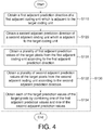
- FIG. 4 shows a flowchart of a method for intra prediction in image encoding according to one embodiment
- FIGS. 5 to 6 illustrate the steps in FIG. 4
- the system 1000 performs the intra prediction for a target coding unit B19.
- the direction unit 110 obtains a first adjacent prediction direction D11 of a first adjacent coding unit B11 which is adjacent to the target coding unit B19.
- the first adjacent coding unit B11 is composed of a plurality of columns and a plurality of rows.
- the first adjacent coding unit B11 has been performed the intra prediction, and the first adjacent prediction direction D11 is mainly used for the intra prediction.
- step S120 the direction unit 110 obtains a second adjacent prediction direction D12 of a second adjacent coding unit B12 which is adjacent to the target coding unit B19.
- the second adjacent coding unit B12 is different from the first adjacent coding unit B11.
- the second adjacent coding unit B12 is composed of a plurality of columns and a plurality of rows.
- the second adjacent coding unit B12 has been performed the intra prediction, and the second adjacent prediction direction D12 is mainly used for the intra prediction.
- the first adjacent coding unit B11 is located at a first side L11 of the target coding unit B19
- the second adjacent coding unit B12 is located at a second side L12 of the target coding unit B19.
- the first side L11 is connected to the second side L12.
- the sequence of the step S110 and the step S120 is not limited to the embodiment of FIG. 4 .
- the S120 can be performed before the step S110.
- the step S110 and the step S120 can be performed at the same time.
- step S130 the prediction unit 130 obtains a plurality of target prediction values V19 (shown in FIG. 3 ) of a plurality of target pixels P19 of the target coding unit B19 from the first adjacent coding unit B11 and the second adjacent coding unit B12 at least according to the first adjacent prediction direction D11 and the second adjacent prediction direction D12.
- the step S130 includes steps S131, S132, S134.
- a first predictor 131 of the prediction unit 130 obtains a plurality of first adjacent prediction values V11 of the target pixels P19 from the first adjacent coding unit B11 according to the first adjacent prediction direction D11.
- the first predictor 131 may copy the pixel values of a plurality of adjacent pixels P11 of the first adjacent coding unit B11 to the target pixels P19 along the first adjacent prediction direction D11 to obtain the first adjacent prediction values V11 of the target pixels P19.
- the content copied by the first predictor 131 is related to the first adjacent prediction direction D11.
- the content copied by the first predictor 131 may be the content of the second adjacent coding unit B12 located at the left side.
- a second predictor 132 of the prediction unit 130 obtains a plurality of second adjacent prediction values V12 of the target pixels P19 from the second adjacent coding unit B12 according to the second adjacent prediction direction D12.
- the second predictor 132 may copy the pixel values of a plurality of adjacent pixels P12 of the second adjacent coding unit B12 to the target pixels P19 along the second adjacent prediction direction D12 to obtain the second adjacent prediction values V12 of the target pixels P19.
- the content copied by the second predictor 132 is related to the second adjacent prediction direction D12.
- the content copied by the second predictor 132 may be the content of the first adjacent coding unit B11 located at the right side.
- step S131 and the step S132 are not limited to the embodiment of FIG. 4 .
- the step S132 may be performed before the step S131.
- the step S131 and the step S132 may be performed at the same time.
- step S134 the combiner 134 of the prediction unit 130 obtains each of the target prediction values V19 of the target pixels P19 by combining one of the first adjacent prediction values V11 and one of the second adjacent prediction values V12.
- the combiner 134 obtains each of the target prediction values V19 according to the equation (1).
- the combiner 134 obtains each of the target prediction values V19 by summing up a product of one of the first adjacent prediction values V11 and one of a plurality of first weightings W11 and a product of one of the second adjacent prediction values V12 and one of a plurality of second weightings W12.
- the first weightings W11 are different from the second weightings W12.
- the first weightings W11 and the second weightings W12 are provided by the weighting unit 140.
- the first weighting W11 corresponding to one target pixel P19 is a function of the location, the first adjacent prediction value V11 and the second adjacent prediction value V12, and is changed with the location.
- the second weighting W12 corresponding to the target pixel P19 is a function of the location, the first adjacent prediction value V11 and the second adjacent prediction value V12, and is changed with the location.
- FIG. 7 illustrates the step S134 according to one embodiment.
- the combiner 134 obtains the target prediction values V19 according to the equation (2).
- V 19 x y x + 1 x + 1 + y + 1 ⁇ V 11 x y + y + 1 x + 1 + y + 1 ⁇ V 12 x y
- the first weighting W11 is x + 1 x + 1 + y + 1
- the second weighting W12 is y + 1 x + 1 + y + 1 . That is to say, if the target pixel P19 is far away from the first adjacent coding unit B11, (y+1) is large and the first weighting W11 x + 1 x + 1 + y + 1 is small; if the target pixel P19 is near to the first adjacent coding unit B11, (y+1) is small and the first weighting W11 x + 1 x + 1 + y + 1 is large.
- the target prediction value V19 is highly related to the first adjacent prediction value V11; if the target pixel P19 is near to the second adjacent coding unit B12, the target prediction value V19 is highly related to the second adjacent prediction value V12.
- FIG. 8 illustrates the step S134 according to another embodiment.
- a first distance ds1 between the target pixel P19 and the first adjacent coding unit B11 is measured.
- a second distance ds2 between the target pixel P19 and the second adjacent coding unit B12 is measured.
- the combiner 134 obtains the target prediction values V19 according to the equation (3).
- V 19 x y ds 2 ds 1 + ds 2 ⁇ V 11 x y + ds 1 ds 1 + ds 2 ⁇ V 12 x y
- the first weighting W11 is ds 2 ds 1 + ds 2
- the second weighting W12 is ds 1 ds 1 + ds 2 . That is to say, if the first distance ds1 between the target pixel P19 and the first adjacent coding unit B11 is large, the first weighting W11 ds 2 ds 1 + ds 2 is small; if the first distance ds1 between the target pixel P19 and the first adjacent coding unit B11 is small, the first weighting W11 ds 2 ds 1 + ds 2 is large.
- the second weighting W12 ds 1 ds 1 + ds 2 is small; if the second distance ds2 between the target pixel P19 and the second adjacent coding unit B12 is small, the second weighting W12 ds 1 ds 1 + ds 2 is large.
- the target prediction value V19 is highly related to the first adjacent prediction value V11; if the target pixel P19 is near to the second adjacent coding unit B12, the target prediction value V19 is highly related to the second adjacent prediction value V12.
- FIG. 9 shows a system 2000 for intra prediction in image encoding according to another embodiment
- FIG. 10 shows a flowchart of a method for intra prediction in image encoding according to one embodiment
- FIG. 11 illustrates the step S230 of FIG. 10 .
- the direction unit 210 obtains the first adjacent prediction direction D11 and the second adjacent prediction direction D12.
- the steps S210, S220 are similar to the steps S110, S120, and similarities are not repeated here.
- the step S230 includes steps S233, S231, S232, S234.
- a third predictor 233 of a prediction unit 230 obtains a plurality of predetermined prediction values V20 of the target pixels P19 from the first adjacent coding unit B11 and/or the second adjacent coding unit B12 according to the predetermined prediction direction D20.
- the predetermined prediction direction D20 is preset for the whole image and is unchanged during the calculation.
- the third predictor 233 may copy the pixel values of the first adjacent coding unit B11 and/or second adjacent coding unit B12 to the target pixels P19 along the predetermined prediction direction D20 to obtain the predetermined prediction values V20 of the target pixels P19.
- a first predictor 231 of the prediction unit 230 obtains the first adjacent prediction values V11 of the target pixels P19 from the first adjacent coding unit B11 according to the first adjacent prediction direction D11. For example, referring to right portion of FIG. 11 , the first predictor 231 can copy the pixel values of the adjacent pixels P11 of the first adjacent coding unit B11 to the target pixels P19 along the first adjacent prediction direction D11 to obtain the first adjacent prediction values V11.
- a second predictor of the prediction unit 230 obtains the second adjacent prediction values V12 of the target pixels P19 from the second adjacent coding unit B12 according to the second adjacent prediction direction D12.
- the second predictor 232 can copy the pixel values of the adjacent pixels P12 of the second adjacent coding unit B12 to the target pixels P19 along the second adjacent prediction direction D12 to obtain the second adjacent prediction values V12.
- a combiner 234 of the prediction unit 230 obtains each of the target prediction values V29 of the target pixels P19 by combining one of the predetermined prediction value V20, one of the first adjacent prediction values V11 and one of the second adjacent prediction values V12. For example, the combiner 234 obtains the target prediction values V29 according to the equation (4).
- the combiner 234 obtains each of the target prediction values V29 by summing up a product of one of the first adjacent prediction values V11 and one of a plurality of first weightings W21, a product of one of the second adjacent prediction values V12 and one of a plurality of second weightings W22, and a product of one of the predetermined prediction values V20 and one of a plurality of third weightings W23.
- the first weightings W21, the second weightings W22 and the third weightings W23 are different.
- the first weightings W21, the second weightings W22 and the third weightings W23 are provided by a weighting unit 240.
- the first weighting W21 corresponding to one target pixel P19 is a function of the location, the first adjacent prediction value V11, the second adjacent prediction value V12 and the predetermined prediction value V20, and is changed with the location.
- the second weighting W22 corresponding to one target pixel P19 is a function of the location, the first adjacent prediction value V11, the second adjacent prediction value V12 and the predetermined prediction value V20, and is changed with the location.
- the third weighting W23 corresponding to one target pixel P19 is a function of the location, the first adjacent prediction value V11, the second adjacent prediction value V12 and the predetermined prediction value V20, and is changed with the location.
- the prediction unit 230 can perform the intra prediction according to the predetermined prediction direction D20.
- FIG. 12 shows a system 3000 for intra prediction in image encoding according to another embodiment
- FIG. 13 shows a flowchart of a method for intra prediction in image encoding according to another embodiment
- FIG. 14 illustrates the step S330 in FIG. 12
- steps S310 and S320 a direction unit 310 obtains the first adjacent prediction direction D11 and the second adjacent prediction direction D12.
- the steps S310, S320 are similar to the steps S110, S120.
- the step S330 includes steps S331, S332, S334.
- a first predictor 331 of the prediction unit 330 obtains the first adjacent prediction values V11 of the target pixels P19 from the first adjacent coding unit B11 according to the first adjacent prediction direction D11.
- a second predictor 332 of the prediction unit 330 obtains the second adjacent prediction values V12 of the target pixels P19 from the second adjacent coding unit B12 according to the second adjacent prediction direction D12.
- a selector 334 of the prediction unit 230 chooses some of the first adjacent prediction values V11 as part of the target prediction values V39 of the target pixels P19, and chooses some of the second adjacent prediction values V12 as another part of the target prediction values V39 of the target pixels P19.
- the selector 334 obtains the target prediction values V39 according to the equation (5).
- the selector 334 chooses the first adjacent prediction value V11 as the target prediction value V39 (shown in FIG. 12 ); if the target pixel P19 is near to the second adjacent coding unit B12, the selector 334 chooses the second adjacent prediction value V12 as the target prediction value V39; if the target pixel P19 is located at a slant axis L1, the selector 334 chooses the average of the first adjacent prediction value V11 and the second adjacent prediction value V12 as the target prediction value V39.
- the prediction unit 330 can perform the intra prediction via the selection.
- the muti-prediction direction technology is used in the intra prediction to improve the compression efficiency of the panoramic image in order to meet the needs of the future.
Abstract
Description
- The disclosure relates in general to a method and a system for intra prediction in image encoding.
- Along with the development of the computer, network communication and display, 360 degree panoramic video having high dynamic range and virtual reality function is more and more widely used. In order to get a good user experience, the resolution of these videos is usually very high. Moreover, if the user uses a head-mounted display to play the 360 degree panoramic video, the distance between the eyes and the display is close, such that the picture becomes rough and the user's viewing experience is affected. Therefore, in order to make the display finer, the resolution of the display becomes high, and the display refresh rate is raised to 30 to 90, as such the data transmission becomes large. Thus, it is needed to invent an image encoding method having high compression efficiency in order to meet the needs of the future.
- The disclosure is directed to a method and a system for intra prediction in image encoding.
- According to one embodiment, a method for intra prediction in image encoding is provided. The method is for performing an intra prediction of a target coding unit. The method includes the following steps. A first adjacent prediction direction of a first adjacent coding unit which is adjacent to the target coding unit is obtained. A second adjacent prediction direction of a second adjacent coding unit which is adjacent to the target coding unit is obtained. The second adjacent coding unit is different from the first adjacent coding unit. A plurality of target prediction values of a plurality of target pixels of the target coding unit is obtained from the first adjacent coding unit and the second adjacent coding unit at least according to the first adjacent prediction direction and the second adjacent prediction direction.
- According to another embodiment, a system for intra prediction in image encoding is provided. The system is for performing an intra prediction of a target coding unit. The system includes a direction unit and a prediction unit. The direction unit is for obtaining a first adjacent prediction direction of a first adjacent coding unit which is adjacent to the target coding unit and obtaining a second adjacent prediction direction of a second adjacent coding unit which is adjacent to the target coding unit. The second adjacent coding unit is different from the first adjacent coding unit. The prediction unit is for obtaining a plurality of target prediction values of a plurality of target pixels of the target coding unit from the first adjacent coding unit and the second adjacent coding unit at least according to the first adjacent prediction direction and the second adjacent prediction direction.
-
-
FIG. 1 illustrates an intra prediction in image encoding. -
FIG. 2 shows a panoramic image. -
FIG. 3 shows a system for intra prediction in image encoding according to one embodiment. -
FIG. 4 shows a flowchart of a method for intra prediction in image encoding according to one embodiment. -
FIGS. 5 to 6 illustrate the steps inFIG. 4 . -
FIG. 7 illustrates the step S134 according to one embodiment. -
FIG. 8 illustrates the step S134 according to another embodiment. -
FIG. 9 shows a system for intra prediction in image encoding according to another embodiment. -
FIG. 10 shows a flowchart of a method for intra prediction in image encoding according to one embodiment. -
FIG. 11 illustrates the step S230 ofFIG. 10 . -
FIG. 12 shows a system for intra prediction in image encoding according to another embodiment. -
FIG. 13 shows a flowchart of a method for intra prediction in image encoding according to another embodiment. -
FIG. 14 illustrates the step S330 inFIG. 12 . - In the following detailed description, for purposes of explanation, numerous specific details are set forth in order to provide a thorough understanding of the disclosed embodiments. It will be apparent, however, that one or more embodiments may be practiced without these specific details. In other instances, well-known structures and devices are schematically shown in order to simplify the drawing.
- Please refer to
FIG. 1 , which illustrates an intra prediction in image encoding. In the intra prediction, a plurality of original values V99 of a plurality of target pixels P99 in a target coding unit B99 are provided. A plurality of target prediction values V91 of the target pixels P99 in the target coding unit B99 are obtained from a plurality of adjacent pixels P91 according to a predetermined prediction direction D91. The target prediction values V91 are also called as prediction block. - Next, differences between the original values V99 and the target prediction values V91 are calculated to obtain a plurality of residual values V92 of the target coding unit B99. The residual values V92 are also called as residual block. As shown in
FIG. 1 , the number of bits of each residual value V92 is low, so the compression efficiency is improved. - Please refer to
FIG. 2 , which shows apanoramic image 900. In thepanoramic image 900, part of the content is bent. Referring to the block B900 at the lower right corner, texture T900 in the block B900 is bent. Referring to the block B900 at the upper right corner, a predetermined prediction direction D900 is greatly different from the texture T900, so the compression efficiency may be affected. - Please refer to
FIG. 3 , which shows asystem 1000 for intra prediction in image encoding according to one embodiment. Thesystem 1000 includes adirection unit 110, aprediction unit 130 and aweighting unit 140. Thedirection unit 110 is used for obtaining a prediction direction. Theprediction unit 130 is used for performing the intra prediction. Theweighting unit 140 is used for providing weightings. Each of thedirection unit 110, theprediction unit 130 and theweighting unit 140 may be a chip, a circuit, a circuit board, or a non-transitory computer readable medium. Thesystem 1000 can improve the compression efficiency via muti-prediction direction technology. The operation of those elements is illustrated via a flowchart. - Please refer
FIGS. 4 to 6 .FIG. 4 shows a flowchart of a method for intra prediction in image encoding according to one embodiment, andFIGS. 5 to 6 illustrate the steps inFIG. 4 . As shown inFIG. 5 , thesystem 1000 performs the intra prediction for a target coding unit B19. In step S110, thedirection unit 110 obtains a first adjacent prediction direction D11 of a first adjacent coding unit B11 which is adjacent to the target coding unit B19. The first adjacent coding unit B11 is composed of a plurality of columns and a plurality of rows. The first adjacent coding unit B11 has been performed the intra prediction, and the first adjacent prediction direction D11 is mainly used for the intra prediction. - Then, in step S120, the
direction unit 110 obtains a second adjacent prediction direction D12 of a second adjacent coding unit B12 which is adjacent to the target coding unit B19. The second adjacent coding unit B12 is different from the first adjacent coding unit B11. The second adjacent coding unit B12 is composed of a plurality of columns and a plurality of rows. The second adjacent coding unit B12 has been performed the intra prediction, and the second adjacent prediction direction D12 is mainly used for the intra prediction. - As shown in
FIG. 5 , the first adjacent coding unit B11 is located at a first side L11 of the target coding unit B19, and the second adjacent coding unit B12 is located at a second side L12 of the target coding unit B19. The first side L11 is connected to the second side L12. - The sequence of the step S110 and the step S120 is not limited to the embodiment of
FIG. 4 . In one embodiment, the S120 can be performed before the step S110. Or, the step S110 and the step S120 can be performed at the same time. - Next, in step S130, the
prediction unit 130 obtains a plurality of target prediction values V19 (shown inFIG. 3 ) of a plurality of target pixels P19 of the target coding unit B19 from the first adjacent coding unit B11 and the second adjacent coding unit B12 at least according to the first adjacent prediction direction D11 and the second adjacent prediction direction D12. - In the embodiment of
FIG. 4 , the step S130 includes steps S131, S132, S134. In step S131, afirst predictor 131 of theprediction unit 130 obtains a plurality of first adjacent prediction values V11 of the target pixels P19 from the first adjacent coding unit B11 according to the first adjacent prediction direction D11. For example, referring to right portion ofFIG. 6 , thefirst predictor 131 may copy the pixel values of a plurality of adjacent pixels P11 of the first adjacent coding unit B11 to the target pixels P19 along the first adjacent prediction direction D11 to obtain the first adjacent prediction values V11 of the target pixels P19. It is noted that the content copied by thefirst predictor 131 is related to the first adjacent prediction direction D11. The content copied by thefirst predictor 131 may be the content of the second adjacent coding unit B12 located at the left side. - Afterwards, in step S132, a second predictor 132 of the
prediction unit 130 obtains a plurality of second adjacent prediction values V12 of the target pixels P19 from the second adjacent coding unit B12 according to the second adjacent prediction direction D12. For example, referring to left portion ofFIG. 6 , the second predictor 132 may copy the pixel values of a plurality of adjacent pixels P12 of the second adjacent coding unit B12 to the target pixels P19 along the second adjacent prediction direction D12 to obtain the second adjacent prediction values V12 of the target pixels P19. It is noted that the content copied by the second predictor 132 is related to the second adjacent prediction direction D12. The content copied by the second predictor 132 may be the content of the first adjacent coding unit B11 located at the right side. - The sequence of the step S131 and the step S132 is not limited to the embodiment of
FIG. 4 . In one embodiment, the step S132 may be performed before the step S131. Or, the step S131 and the step S132 may be performed at the same time. - Then, in step S134, the
combiner 134 of theprediction unit 130 obtains each of the target prediction values V19 of the target pixels P19 by combining one of the first adjacent prediction values V11 and one of the second adjacent prediction values V12. For example, thecombiner 134 obtains each of the target prediction values V19 according to the equation (1).
- The
combiner 134 obtains each of the target prediction values V19 by summing up a product of one of the first adjacent prediction values V11 and one of a plurality of first weightings W11 and a product of one of the second adjacent prediction values V12 and one of a plurality of second weightings W12. In one embodiment, the first weightings W11 are different from the second weightings W12. The first weightings W11 and the second weightings W12 are provided by theweighting unit 140. - As shown in equation (1), the first weighting W11 corresponding to one target pixel P19 is a function of the location, the first adjacent prediction value V11 and the second adjacent prediction value V12, and is changed with the location. The second weighting W12 corresponding to the target pixel P19 is a function of the location, the first adjacent prediction value V11 and the second adjacent prediction value V12, and is changed with the location.
- For example, refer please to
FIG. 7. FIG. 7 illustrates the step S134 according to one embodiment. In one embodiment, thecombiner 134 obtains the target prediction values V19 according to the equation (2).
- In the equation (2), the first weighting W11 is


- If the target pixel P19 is far away from the second adjacent coding unit B12, (x+1) is large and the second weighting W12


- Therefore, during the calculation of the target prediction value V19, if the target pixel P19 is near to the first adjacent coding unit B11, the target prediction value V19 is highly related to the first adjacent prediction value V11; if the target pixel P19 is near to the second adjacent coding unit B12, the target prediction value V19 is highly related to the second adjacent prediction value V12.
- Moreover, please refer to
FIG. 8 , which illustrates the step S134 according to another embodiment. Along the first adjacent prediction direction D11, a first distance ds1 between the target pixel P19 and the first adjacent coding unit B11 is measured. Along the second adjacent prediction direction D12, a second distance ds2 between the target pixel P19 and the second adjacent coding unit B12 is measured. In another embodiment, thecombiner 134 obtains the target prediction values V19 according to the equation (3).
- In the equation (3), the first weighting W11 is


weighting W11 
weighting W11 
- If the second distance ds2 between the target pixel P19 and the second adjacent coding unit B12 is large, the second weighting W12


- Therefore, during the calculation of the target prediction value V19, if the target pixel P19 is near to the first adjacent coding unit B11, the target prediction value V19 is highly related to the first adjacent prediction value V11; if the target pixel P19 is near to the second adjacent coding unit B12, the target prediction value V19 is highly related to the second adjacent prediction value V12.
- Except the first adjacent prediction direction D11 and the second adjacent prediction direction D12, a predetermined prediction direction D20 can be used for intra prediction. Please refer
FIGS. 9 to 11 .FIG. 9 shows asystem 2000 for intra prediction in image encoding according to another embodiment,FIG. 10 shows a flowchart of a method for intra prediction in image encoding according to one embodiment, andFIG. 11 illustrates the step S230 ofFIG. 10 . In steps S210, S220, thedirection unit 210 obtains the first adjacent prediction direction D11 and the second adjacent prediction direction D12. The steps S210, S220 are similar to the steps S110, S120, and similarities are not repeated here. - The step S230 includes steps S233, S231, S232, S234. In step S233, a
third predictor 233 of aprediction unit 230 obtains a plurality of predetermined prediction values V20 of the target pixels P19 from the first adjacent coding unit B11 and/or the second adjacent coding unit B12 according to the predetermined prediction direction D20. The predetermined prediction direction D20 is preset for the whole image and is unchanged during the calculation. For example, referring to upper portion ofFIG. 11 , thethird predictor 233 may copy the pixel values of the first adjacent coding unit B11 and/or second adjacent coding unit B12 to the target pixels P19 along the predetermined prediction direction D20 to obtain the predetermined prediction values V20 of the target pixels P19. - Next, in step S231, a
first predictor 231 of theprediction unit 230 obtains the first adjacent prediction values V11 of the target pixels P19 from the first adjacent coding unit B11 according to the first adjacent prediction direction D11. For example, referring to right portion ofFIG. 11 , thefirst predictor 231 can copy the pixel values of the adjacent pixels P11 of the first adjacent coding unit B11 to the target pixels P19 along the first adjacent prediction direction D11 to obtain the first adjacent prediction values V11. - Then, in step S232, a second predictor of the
prediction unit 230 obtains the second adjacent prediction values V12 of the target pixels P19 from the second adjacent coding unit B12 according to the second adjacent prediction direction D12. For example, referring to left portion ofFIG. 11 , thesecond predictor 232 can copy the pixel values of the adjacent pixels P12 of the second adjacent coding unit B12 to the target pixels P19 along the second adjacent prediction direction D12 to obtain the second adjacent prediction values V12. - Afterwards, in step S234, a
combiner 234 of theprediction unit 230 obtains each of the target prediction values V29 of the target pixels P19 by combining one of the predetermined prediction value V20, one of the first adjacent prediction values V11 and one of the second adjacent prediction values V12. For example, thecombiner 234 obtains the target prediction values V29 according to the equation (4).
- The
combiner 234 obtains each of the target prediction values V29 by summing up a product of one of the first adjacent prediction values V11 and one of a plurality of first weightings W21, a product of one of the second adjacent prediction values V12 and one of a plurality of second weightings W22, and a product of one of the predetermined prediction values V20 and one of a plurality of third weightings W23. The first weightings W21, the second weightings W22 and the third weightings W23 are different. The first weightings W21, the second weightings W22 and the third weightings W23 are provided by a weighting unit 240. - As shown in equation (4), the first weighting W21 corresponding to one target pixel P19 is a function of the location, the first adjacent prediction value V11, the second adjacent prediction value V12 and the predetermined prediction value V20, and is changed with the location. The second weighting W22 corresponding to one target pixel P19 is a function of the location, the first adjacent prediction value V11, the second adjacent prediction value V12 and the predetermined prediction value V20, and is changed with the location. The third weighting W23 corresponding to one target pixel P19 is a function of the location, the first adjacent prediction value V11, the second adjacent prediction value V12 and the predetermined prediction value V20, and is changed with the location.
- That is to say, expect the first adjacent prediction direction D11 and the second adjacent prediction direction D12, the
prediction unit 230 can perform the intra prediction according to the predetermined prediction direction D20. - Furthermore, in another embodiment, expect the combination the intra prediction can be performed via selection. Please refer to
FIGS. 12 to 14 .FIG. 12 shows asystem 3000 for intra prediction in image encoding according to another embodiment,FIG. 13 shows a flowchart of a method for intra prediction in image encoding according to another embodiment, andFIG. 14 illustrates the step S330 inFIG. 12 . In steps S310 and S320, adirection unit 310 obtains the first adjacent prediction direction D11 and the second adjacent prediction direction D12. The steps S310, S320 are similar to the steps S110, S120. - The step S330 includes steps S331, S332, S334. In step S331, a
first predictor 331 of theprediction unit 330 obtains the first adjacent prediction values V11 of the target pixels P19 from the first adjacent coding unit B11 according to the first adjacent prediction direction D11. - Then, in step S332, a
second predictor 332 of theprediction unit 330 obtains the second adjacent prediction values V12 of the target pixels P19 from the second adjacent coding unit B12 according to the second adjacent prediction direction D12. - Afterwards, in step S334, a
selector 334 of theprediction unit 230 chooses some of the first adjacent prediction values V11 as part of the target prediction values V39 of the target pixels P19, and chooses some of the second adjacent prediction values V12 as another part of the target prediction values V39 of the target pixels P19. For example, theselector 334 obtains the target prediction values V39 according to the equation (5).
- If the target pixel P19 is near to the first adjacent coding unit B11, the
selector 334 chooses the first adjacent prediction value V11 as the target prediction value V39 (shown inFIG. 12 ); if the target pixel P19 is near to the second adjacent coding unit B12, theselector 334 chooses the second adjacent prediction value V12 as the target prediction value V39; if the target pixel P19 is located at a slant axis L1, theselector 334 chooses the average of the first adjacent prediction value V11 and the second adjacent prediction value V12 as the target prediction value V39. - That is to say, expect the combination, the
prediction unit 330 can perform the intra prediction via the selection. - According to the embodiments described above, the muti-prediction direction technology is used in the intra prediction to improve the compression efficiency of the panoramic image in order to meet the needs of the future.
- It will be apparent to those skilled in the art that various modifications and variations can be made to the disclosed embodiments. It is intended that the specification and examples be considered as exemplary only, with a true scope of the disclosure being indicated by the following claims and their equivalents.
Claims (19)
- A method for intra prediction in image encoding, for performing an intra prediction of a target coding unit (B19), the method comprising:obtaining a first adjacent prediction direction (D11) of a first adjacent coding unit (B11) which is adjacent to the target coding unit (B19);obtaining a second adjacent prediction direction (D12) of a second adjacent coding unit (B12) which is adjacent to the target coding unit (B19), wherein the second adjacent coding unit (B12) is different from the first adjacent coding unit (B11); andobtaining a plurality of target prediction values (V19) of a plurality of target pixels (P19) of the target coding unit (B19) from the first adjacent coding unit (B11) and the second adjacent coding unit (B12) at least according to the first adjacent prediction direction (D11) and the second adjacent prediction direction (D12).
- The method for intra prediction in image encoding according to claim 1, wherein the step of obtaining the target prediction values of the target coding unit includes:obtaining a plurality of first adjacent prediction values of the target pixels from the first adjacent coding unit according to the first adjacent prediction direction;obtaining a plurality of second adjacent prediction values of the target pixels from the second adjacent coding unit according to the second adjacent prediction direction; andobtaining each of the target prediction values of the target pixels by combining one of the first adjacent prediction values and one of the second adjacent prediction values.
- The method for intra prediction in image encoding according to claim 2, wherein in the step of obtaining each of the target prediction values of the target pixels by combining one of the first adjacent prediction values and one of the second adjacent prediction values, each of the target prediction values is obtained by summing up a product of one of the first adjacent prediction values and one of a plurality of first weightings and a product of one of the second adjacent prediction values and one of a plurality of second weightings.
- The method for intra prediction in image encoding according to claim 3, wherein not all of the first weightings corresponding to the target pixels are identical, and not all of the second weightings corresponding to the target pixels are identical.
- The method for intra prediction in image encoding according to claim 1, wherein the step of obtaining the target prediction values of the target coding unit includes:obtaining a plurality of predetermined prediction values of the target pixels from the first adjacent coding unit or the second adjacent coding unit according to a predetermined prediction direction;obtaining a plurality of first adjacent prediction values of the target pixels from the first adjacent coding unit according to the first adjacent prediction direction;obtaining a plurality of second adjacent prediction values of the target pixels from the second adjacent coding unit according to the second adjacent prediction direction; andobtaining each of the target prediction values of the target pixels by combining one of the predetermined prediction values, one of the first adjacent prediction values and one of the second adjacent prediction values.
- The method for intra prediction in image encoding according to claim 5, wherein in the step of obtaining each of the target prediction values of the target pixels by combining one of the predetermined prediction values, one of the first adjacent prediction values and one of the second adjacent prediction values, each of the target prediction values is obtained by summing up a product of one of the predetermined prediction values and one of a plurality of third weightings, a product of one of the first adjacent prediction values and one of a plurality of first weightings and a product of one of the second adjacent prediction values and one of a plurality of second weightings.
- The method for intra prediction in image encoding according to claim 6, wherein not all of the third weightings corresponding to the target pixels are identical, not all of the first weightings corresponding to the target pixels are identical, and not all of the second weightings corresponding to the target pixels are identical.
- The method for intra prediction in image encoding according to claim 6, wherein each of the third weightings is related to a location of one of the target pixels, each of the first weightings is related to the location of one of the target pixels, and each of the second weightings is related to the location of one of the target pixels.
- The method for intra prediction in image encoding according to claim 6, wherein each of the third weightings is related to one of the predetermined prediction values, one of the first adjacent prediction values and one of the second adjacent prediction values, each of the first weightings is related to one of the predetermined prediction values, one of the first adjacent prediction values and one of the second adjacent prediction values, and each of the second weightings is related to one of the predetermined prediction values, one of the first adjacent prediction values and one of the second adjacent prediction values.
- The method for intra prediction in image encoding according to claim 1, wherein the step of obtaining the target prediction values of the target coding unit includes:obtaining a plurality of first adjacent prediction values of the target pixels from the first adjacent coding unit according to the first adjacent prediction direction;obtaining a plurality of second adjacent prediction values of the target pixels from the second adjacent coding unit according to the second adjacent prediction direction; andchoosing some of the first adjacent prediction values as part of the target prediction values, and choosing some of the second adjacent prediction values as another part of the target prediction values.
- The method for intra prediction in image encoding according to claim 1, wherein the first adjacent coding unit is located at a first side of the target coding unit, the second adjacent coding unit is located at a second side of the target coding unit.
- The method for intra prediction in image encoding according to claim 11, wherein the first side is connected to the second side.
- A system for intra prediction in image encoding, for performing an intra prediction of a target coding unit (B19), the system comprising:a direction unit (110) for obtaining a first adjacent prediction direction (D11) of a first adjacent coding unit (B11) which is adjacent to the target coding unit (B19) and obtaining a second adjacent prediction direction (D12) of a second adjacent coding unit (B12) which is adjacent to the target coding unit (B19), wherein the second adjacent coding unit (B12) is different from the first adjacent coding unit (B11); anda prediction unit (130) for obtaining a plurality of target prediction values (V19) of a plurality of target pixels (P19) of the target coding unit (B19) from the first adjacent coding unit (B11) and the second adjacent coding unit (B12) at least according to the first adjacent prediction direction (D11) and the second adjacent prediction direction (D12).
- The system for intra prediction in image encoding according to claim 13, wherein the prediction unit includes:a first predictor for obtaining a plurality of first adjacent prediction values of the target pixels from the first adjacent coding unit according to the first adjacent prediction direction;a second predictor for obtaining a plurality of second adjacent prediction values of the target pixels from the second adjacent coding unit according to the second adjacent prediction direction;a combiner for obtaining each of the target prediction values of the target pixels by combining one of the first adjacent prediction values and one of the second adjacent prediction values; anda weighting unit for providing a plurality of first weightings and a plurality of second weightings for the target pixels;wherein the combiner obtains each of the target prediction values by summing up a product of one of the first adjacent prediction values and one of a plurality of first weightings and a product of one of the second adjacent prediction values and one of a plurality of second weightings; andnot all of the first weightings corresponding to the target pixels are identical; andnot all of the second weightings corresponding to the target pixels are identical.
- The system for intra prediction in image encoding according to claim 13, wherein the prediction unit includes:a first predictor for obtaining a plurality of first adjacent prediction values of the target pixels from the first adjacent coding unit according to the first adjacent prediction direction;a second predictor for obtaining a plurality of second adjacent prediction values of the target pixels from the second adjacent coding unit according to the second adjacent prediction direction;a third predictor for obtaining a plurality of predetermined prediction values of the target pixels from the first adjacent coding unit or the second adjacent coding unit according to a predetermined prediction direction;a combiner for obtaining each of the target prediction values of the target pixels by combining one of the predetermined prediction values, one of the first adjacent prediction values and one of the second adjacent prediction values; anda weighting unit for providing a plurality of first weightings, a plurality of second weightings and a plurality of third weightings for the target pixels;wherein the combiner obtains each of the target prediction values by summing up a product of one of the predetermined prediction values and one of a plurality of third weightings, a product of one of the first adjacent prediction values and one of a plurality of first weightings and a product of one of the second adjacent prediction values and one of a plurality of second weightings.
- The system for intra prediction in image encoding according to claim 15, wherein not all of the third weightings corresponding to the target pixels are identical, not all of the first weightings corresponding to the target pixels are identical, and not all of the second weightings corresponding to the target pixels are identical.
- The system for intra prediction in image encoding according to claim 15, wherein each of the third weightings is related to a location of one of the target pixels, each of the first weightings is related to the location of one of the target pixels, and each of the second weightings is related to the location of one of the target pixels.
- The system for intra prediction in image encoding according to claim 15, wherein each of the third weightings is related to one of the predetermined prediction values, one of the first adjacent prediction values and one of the second adjacent prediction values, each of the first weightings is related to one of the predetermined prediction values, one of the first adjacent prediction values and one of the second adjacent prediction values, and each of the second weightings is related to one of the predetermined prediction values, one of the first adjacent prediction values and one of the second adjacent prediction values.
- The system for intra prediction in image encoding according to claim 13, wherein the prediction unit includes:a first predictor for obtaining a plurality of first adjacent prediction values of the target pixels from the first adjacent coding unit according to the first adjacent prediction direction;a second predictor for obtaining a plurality of second adjacent prediction values of the target pixels from the second adjacent coding unit according to the second adjacent prediction direction; anda selector for choosing some of the first adjacent prediction values as part of the target prediction values, and choosing some of the second adjacent prediction values as another part of the target prediction values as part of the second adjacent prediction values.
Applications Claiming Priority (2)
| Application Number | Priority Date | Filing Date | Title |
|---|---|---|---|
| US201762528545P | 2017-07-05 | 2017-07-05 | |
| US15/852,392 US20190014324A1 (en) | 2017-07-05 | 2017-12-22 | Method and system for intra prediction in image encoding |
Publications (1)
| Publication Number | Publication Date |
|---|---|
| EP3425916A1 true EP3425916A1 (en) | 2019-01-09 |
Family
ID=62874650
Family Applications (1)
| Application Number | Title | Priority Date | Filing Date |
|---|---|---|---|
| EP18181914.5A Withdrawn EP3425916A1 (en) | 2017-07-05 | 2018-07-05 | Method and system for intra prediction in image encoding |
Country Status (5)
| Country | Link |
|---|---|
| US (1) | US20190014324A1 (en) |
| EP (1) | EP3425916A1 (en) |
| JP (1) | JP2019017062A (en) |
| CN (1) | CN109218723A (en) |
| TW (1) | TWI664854B (en) |
Family Cites Families (6)
| Publication number | Priority date | Publication date | Assignee | Title |
|---|---|---|---|---|
| WO2012057528A2 (en) * | 2010-10-26 | 2012-05-03 | ㈜휴맥스 | Adaptive intra-prediction encoding and decoding method |
| HUE055825T2 (en) * | 2011-10-18 | 2021-12-28 | Lg Electronics Inc | Method for intra prediction and device therefor |
| JP2014131162A (en) * | 2012-12-28 | 2014-07-10 | Nippon Telegr & Teleph Corp <Ntt> | Intra-prediction encoding method, intra-prediction decoding method, intra-prediction encoding device, intra-prediction decoding device, program therefor, and program recorded recording medium |
| WO2015081888A1 (en) * | 2013-12-06 | 2015-06-11 | Mediatek Inc. | Method and apparatus for motion boundary processing |
| US10142626B2 (en) * | 2014-10-31 | 2018-11-27 | Ecole De Technologie Superieure | Method and system for fast mode decision for high efficiency video coding |
| CN106162197B (en) * | 2016-08-31 | 2019-07-12 | 北京奇艺世纪科技有限公司 | A kind of coding intra-frame prediction method and device |
-
2017
- 2017-12-22 US US15/852,392 patent/US20190014324A1/en not_active Abandoned
-
2018
- 2018-01-03 TW TW107100246A patent/TWI664854B/en active
- 2018-01-12 CN CN201810030062.5A patent/CN109218723A/en active Pending
- 2018-05-07 JP JP2018089551A patent/JP2019017062A/en active Pending
- 2018-07-05 EP EP18181914.5A patent/EP3425916A1/en not_active Withdrawn
Non-Patent Citations (2)
| Title |
|---|
| PANUSOPONE K ET AL: "Weighted angular prediction", 6. JVET MEETING; 31-3-2017 - 7-4-2017; HOBART; (THE JOINT VIDEO EXPLORATION TEAM OF ISO/IEC JTC1/SC29/WG11 AND ITU-T SG.16 ); URL: HTTP://PHENIX.INT-EVRY.FR/JVET/,, no. JVET-F0104, 4 April 2017 (2017-04-04), XP030150784 * |
| SHIODERA T ET AL: "CE6 Subset A: Bidirectional intra prediction (JCTVC-C079)", 95. MPEG MEETING; 24-1-2011 - 28-1-2011; DAEGU; (MOTION PICTURE EXPERT GROUP OR ISO/IEC JTC1/SC29/WG11),, no. m18859, 20 January 2011 (2011-01-20), XP030047428 * |
Also Published As
| Publication number | Publication date |
|---|---|
| TW201907723A (en) | 2019-02-16 |
| CN109218723A (en) | 2019-01-15 |
| TWI664854B (en) | 2019-07-01 |
| JP2019017062A (en) | 2019-01-31 |
| US20190014324A1 (en) | 2019-01-10 |
Similar Documents
| Publication | Publication Date | Title |
|---|---|---|
| US11622112B2 (en) | Decomposition of residual data during signal encoding, decoding and reconstruction in a tiered hierarchy | |
| US9679357B2 (en) | Image processing device, and an image processing method | |
| US20180234697A1 (en) | Inter prediction method and apparatus in video coding system | |
| US9135744B2 (en) | Method for filling hole-region and three-dimensional video system using the same | |
| US20240031603A1 (en) | Method and apparatus of encoding/decoding image data based on tree structure-based block division | |
| US10834398B2 (en) | Method for dividing prediction block, encoding device, and decoding device | |
| US11647221B2 (en) | Method and device for image decoding according to inter-prediction in image coding system | |
| US20150334365A1 (en) | Stereoscopic image processing apparatus, stereoscopic image processing method, and recording medium | |
| US11831916B1 (en) | Method and apparatus of encoding/decoding image data based on tree structure-based block division | |
| US10116917B2 (en) | Image processing apparatus, image processing method, and storage medium | |
| US8184707B2 (en) | Method and apparatus for encoding multiview video using hierarchical B frames in view direction, and a storage medium using the same | |
| EP3535975B1 (en) | Apparatus and method for 3d video coding | |
| DE102019215387A1 (en) | CIRCULAR FISH EYE CAMERA ARRAY CORRECTION | |
| Liu et al. | An enhanced depth map based rendering method with directional depth filter and image inpainting | |
| CN116760965B (en) | Panoramic video encoding method, device, computer equipment and storage medium | |
| US9497439B2 (en) | Apparatus and method for fast multiview video coding | |
| EP3425916A1 (en) | Method and system for intra prediction in image encoding | |
| EP2858362A1 (en) | Method, device and system for resizing original depth frame into resized depth frame | |
| US20140092222A1 (en) | Stereoscopic image processing device, stereoscopic image processing method, and recording medium | |
| CN112767293A (en) | Method for acquiring parallax image, electronic device and storage medium | |
| WO2021146933A1 (en) | Next-generation loop filter implementations for adaptive resolution video coding | |
| CN114071138A (en) | Intra-frame prediction encoding method, intra-frame prediction encoding device, and computer-readable medium | |
| CN111447444A (en) | Image processing method and device | |
| WO2023031999A1 (en) | Video information processing device, method, and program | |
| CN111787334B (en) | Filtering method, filter and device for intra-frame prediction |
Legal Events
| Date | Code | Title | Description |
|---|---|---|---|
| PUAI | Public reference made under article 153(3) epc to a published international application that has entered the european phase |
Free format text: ORIGINAL CODE: 0009012 |
|
| STAA | Information on the status of an ep patent application or granted ep patent |
Free format text: STATUS: REQUEST FOR EXAMINATION WAS MADE |
|
| 17P | Request for examination filed |
Effective date: 20180705 |
|
| AK | Designated contracting states |
Kind code of ref document: A1 Designated state(s): AL AT BE BG CH CY CZ DE DK EE ES FI FR GB GR HR HU IE IS IT LI LT LU LV MC MK MT NL NO PL PT RO RS SE SI SK SM TR |
|
| AX | Request for extension of the european patent |
Extension state: BA ME |
|
| STAA | Information on the status of an ep patent application or granted ep patent |
Free format text: STATUS: REQUEST FOR EXAMINATION WAS MADE |
|
| RBV | Designated contracting states (corrected) |
Designated state(s): AL AT BE BG CH CY CZ DE DK EE ES FI FR GB GR HR HU IE IS IT LI LT LU LV MC MK MT NL NO PL PT RO RS SE SI SK SM TR |
|
| STAA | Information on the status of an ep patent application or granted ep patent |
Free format text: STATUS: THE APPLICATION HAS BEEN WITHDRAWN |
|
| 18W | Application withdrawn |
Effective date: 20220713 |