EP3425777A2 - Compound harmonic gear - Google Patents
Compound harmonic gear Download PDFInfo
- Publication number
- EP3425777A2 EP3425777A2 EP18170640.9A EP18170640A EP3425777A2 EP 3425777 A2 EP3425777 A2 EP 3425777A2 EP 18170640 A EP18170640 A EP 18170640A EP 3425777 A2 EP3425777 A2 EP 3425777A2
- Authority
- EP
- European Patent Office
- Prior art keywords
- flex spline
- wave generator
- ground
- flex
- motor
- Prior art date
- Legal status (The legal status is an assumption and is not a legal conclusion. Google has not performed a legal analysis and makes no representation as to the accuracy of the status listed.)
- Granted
Links
Images



Classifications
-
- F—MECHANICAL ENGINEERING; LIGHTING; HEATING; WEAPONS; BLASTING
- F16—ENGINEERING ELEMENTS AND UNITS; GENERAL MEASURES FOR PRODUCING AND MAINTAINING EFFECTIVE FUNCTIONING OF MACHINES OR INSTALLATIONS; THERMAL INSULATION IN GENERAL
- F16H—GEARING
- F16H49/00—Other gearings
- F16H49/001—Wave gearings, e.g. harmonic drive transmissions
-
- H—ELECTRICITY
- H02—GENERATION; CONVERSION OR DISTRIBUTION OF ELECTRIC POWER
- H02K—DYNAMO-ELECTRIC MACHINES
- H02K7/00—Arrangements for handling mechanical energy structurally associated with dynamo-electric machines, e.g. structural association with mechanical driving motors or auxiliary dynamo-electric machines
- H02K7/10—Structural association with clutches, brakes, gears, pulleys or mechanical starters
- H02K7/116—Structural association with clutches, brakes, gears, pulleys or mechanical starters with gears
-
- B—PERFORMING OPERATIONS; TRANSPORTING
- B64—AIRCRAFT; AVIATION; COSMONAUTICS
- B64C—AEROPLANES; HELICOPTERS
- B64C13/00—Control systems or transmitting systems for actuating flying-control surfaces, lift-increasing flaps, air brakes, or spoilers
- B64C13/24—Transmitting means
- B64C13/26—Transmitting means without power amplification or where power amplification is irrelevant
- B64C13/28—Transmitting means without power amplification or where power amplification is irrelevant mechanical
- B64C13/34—Transmitting means without power amplification or where power amplification is irrelevant mechanical using toothed gearing
-
- B—PERFORMING OPERATIONS; TRANSPORTING
- B64—AIRCRAFT; AVIATION; COSMONAUTICS
- B64C—AEROPLANES; HELICOPTERS
- B64C9/00—Adjustable control surfaces or members, e.g. rudders
- B64C2009/005—Ailerons
-
- F—MECHANICAL ENGINEERING; LIGHTING; HEATING; WEAPONS; BLASTING
- F16—ENGINEERING ELEMENTS AND UNITS; GENERAL MEASURES FOR PRODUCING AND MAINTAINING EFFECTIVE FUNCTIONING OF MACHINES OR INSTALLATIONS; THERMAL INSULATION IN GENERAL
- F16H—GEARING
- F16H49/00—Other gearings
- F16H49/001—Wave gearings, e.g. harmonic drive transmissions
- F16H2049/003—Features of the flexsplines therefor
Definitions
- the following description relates to an actuation system for an aircraft and, more specifically, to compound harmonic drive assemblies of a rotary actuator.
- a compound harmonic drive can reduce backlash in a motion-control system.
- a compound harmonic gear of a compound harmonic drive allows high reduction ratios with concentric shafts and relatively low backlash and vibration.
- the structure and operation of a harmonic gear are based upon a relatively simple construction using elasto-mechanical properties of metal.
- the harmonic gear typically includes a wave generator, a flexible (flex) spline and a ring gear.
- the wave generator is an oval or elliptical cam with a thin bearing placed around an outer circumference thereof and is mounted onto a shaft of a motor.
- the flex spline is thin and made of elastic metal with external teeth formed along an outer circumference thereof (or with internal teeth formed along an inner circumference thereof in an inverted harmonic drive).
- the ring gear is a rigid internal gear with internal teeth formed along an inner circumference thereof. the ring gear has a different number of internal teeth than the flex spline has external teeth.
- the ring gear is attached to a gearbox along an outer circumference thereof.
- the wave generator, the flex spline and the ring gear are co-axially aligned with respect to each other.
- the wave generator is mounted on a drive shaft and rotatable such that it imparts a continuously moving elliptical form or wave-like motion to the flex spline.
- This causes a meshing of the external teeth of the flex spline with the internal teeth of the ring gear at respective equidistant points of engagement or connection thereof to progress in a continuously rolling fashion. It also allows for full-teeth axial disengagement or disconnection at the points opposite a minor axis of the wave generator.
- a major axis of the flex spline actually rotates with the wave generator, so the points where the corresponding teeth mesh with each other revolve around a center point at a rate equal to that of the wave generator.
- each complete revolution of the wave generator causes a circumferential displacement of the flex spline in relation to the ring gear. This displacement is always in a direction opposite to that of the rotation of the wave generator. That is, if the wave generator is rotating in a clockwise direction, the displacement of the flex spline is in a counter-clockwise direction and vice versa. In this way, the compound harmonic drive is capable of functioning as a speed reducer.
- a rotary electromechanical actuator (rotary EMA) is implemented mainly for ailerons, flaps, slats and spoiler and other flight-control surfaces.
- the compound harmonic drive is incorporated with the rotary EMA.
- a compound harmonic actuator includes a motor, a flex spline disposed about the motor and a wave generator radially interposable between the motor and the flex spline.
- the wave generator is rotatably drivable by the motor and shaped to form the flex spline into an elliptical shape with an axis such that wave generator rotations drive rotations of the axis of the ellipse of the flex spline.
- the wave generator includes a scalloped outer surface and roller bearings arranged circumferentially about the scalloped outer surface.
- the compound harmonic actuator further includes a ground arm in which the motor is supportively disposable and an output arm which is drivable by the flex spline to pivot within a predefined range of angles relative to the ground arm.
- the wave generator is shaped to form the flex spline into an irregular elliptical shape with multiple major axes.
- the scalloped outer surface includes sequential ridges and lands.
- a distal edge of each ridge is sharp.
- a distal edge of each ridge is radially aligned with or terminal within respective central longitudinal axes of adjacent roller bearings.
- the flex spline is formed as only a single unitary piece.
- the flex spline includes a ground flex spline configured to interface with the wave generator and having a first number of external teeth, an output flex spline configured to interface with an output gear and having a second number of external teeth which is different from the first number and a coupling configured to interface with the respective first and second numbers of external teeth of the ground and output flex splines.
- a compound harmonic actuator includes a motor, a flex spline disposed about the motor and formed as only a single unitary piece and a wave generator radially interposable between the motor and the flex spline.
- the wave generator is rotatably drivable by the motor and shaped to form the flex spline into an elliptical shape with an axis such that wave generator rotations drive rotations of the axis of the ellipse of the flex spline.
- the compound harmonic actuator further includes a ground arm in which the motor is supportively disposable and an output arm which is drivable by the flex spline to pivot within a predefined range of angles relative to the ground arm.
- the wave generator is shaped to form the flex spline into an irregular elliptical shape with multiple major axes.
- the wave generator includes a scalloped outer surface and roller bearings arranged circumferentially about the scalloped outer surface.
- the scalloped outer surface includes sequential ridges and lands.
- Each roller bearing rolls about a central longitudinal axis thereof in a corresponding land.
- the single unitary piece of the flex spline includes a body integrally formed with a smooth interior diameter and external teeth.
- a compound harmonic actuator includes a motor, a flex spline disposed about the motor and a wave generator radially interposable between the motor and the flex spline.
- the wave generator is rotatably drivable by the motor and shaped to form the flex spline into an elliptical shape with an axis such that wave generator rotations drive rotations of the axis of the ellipse of the flex spline.
- the flex spline includes a ground flex spline configured to interface with the wave generator and having a first number of external teeth, an output flex spline configured to interface with an output gear and having a second number of external teeth which is different from the first number and a coupling configured to interface with the respective first and second numbers of external teeth of the ground and output flex splines.
- the compound harmonic actuator further includes a ground arm in which the motor is supportively disposable and an output arm which is drivable by the output flex spline to pivot within a predefined range of angles relative to the ground arm.
- the wave generator is shaped to form the flex spline into an irregular elliptical shape with multiple major axes.
- the wave generator includes a scalloped outer surface and roller bearings arranged circumferentially about the scalloped outer surface.
- the scalloped outer surface includes sequential ridges and lands.
- Each roller bearing rolls about a central longitudinal axis thereof in a corresponding land.
- the coupling includes a first ring gear having internal teeth to interface with the first number of external teeth of the ground flex spline, a second ring gear having internal teeth to interface with the second number of external teeth of the output flex spline and coupling pins disposed to secure the first and second ring gears.
- the ground flex spline is provided as first and second ground flex splines on either side of the output flex spline.
- the coupling includes first ring gears that each have internal teeth to interface with the first number of external teeth of each of the first and second ground flex splines, second ring gears that each have internal teeth to interface with the second number of external teeth of the output flex spline and first and second sets of coupling pins disposed to secure each of the first ring gears to one of the second ring gears.
- a compound harmonic actuator is provided with at least one or more improvements.
- a wave generator of the compound harmonic actuator may include a scalloped outer surface that secures roller bearings in place and negates a need for a cage.
- a flex spline of the wave generator may include only a single unitary piece.
- the flex spline of the wave generator may include a ground flex spline, an output flex spline and a coupling configured to interface with the ground and output flex splines. The first and second improvements may be employed together and the first and third improvements may be employed together.
- the compound harmonic actuator 100 includes a motor 101, a flex spline 102 and a wave generator 103.
- the motor 101 includes an interior stator with windings that are receptive of current and a rotor disposed about the interior stators.
- the rotor includes a circumferential array of magnets such that, when current is supplied to the windings via wiring 1010, a flux moment is induced in the rotor which causes the rotor to rotate. This rotary motion serves to drive corresponding rotations of the wave generator 103.
- the flex spline 102 is disposed about the motor 101 with the wave generator 103 radially interposable between the motor 101 and the flex spline 102.
- the wave generator 103 is rotatably drivable by the motor 101 as noted above and is shaped to form the flex spline 102 into an elliptical shape 201 with a major axis 202 (see FIG. 2 ) or into an irregular elliptical shape 301 with multiple major axes 302 (see FIG. 3 ).
- the rotational driving of the wave generator 103 drives corresponding rotations of the major axis 202 or the major axes 302 of the flex spline 102.
- the flex spline 102 has a number of external teeth that can interface with a number of internal teeth of an output gear, an output arm or a coupling as will be described below. Since the number of the external teeth of the flex spline 102 is different than the number of internal teeth of the output gear, the output arm or the coupling, the rotations of the major axis 202 of the major axes 302 of the flex spline 102 drive corresponding (reverse) and geared-down rotations of the output gear, the output arm or the coupling.
- the compound harmonic actuator 100 may further include one or more ground arms 104 and an output arm 105.
- the motor 101 is supportively disposable within the one or more ground arms 104 and the output arm is drivable by the flex spline 102 to pivot within a predefined range of angles relative to the one or more ground arms 104.
- the compound harmonic actuator 100 may be employed to control certain surfaces of a wing of an aircraft where a relatively large amount of torque is required to pivot an aerodynamic surface relative to another aerodynamic surface.
- the one or more ground arms 104 may be affixed to an aircraft wing spar and the output arm 105 may be affixed to an aileron of the aircraft wing.
- the aileron correspondingly pivots relative to the spar.
- the angular range of such pivoting is limited by software which prevents an over rotation in either direction of the motor 101 and by mechanical features (e.g., the guide 106 of the output arm 105 and the boss 107 of the one or more ground arms 104 which moves through the guide 106 during pivoting).
- the wave generator 103 may include a scalloped outer surface 801 and roller bearings 901 which are arranged circumferentially and side-by-side about the scalloped outer surface 801 and which are respectively secured in placed by each corresponding scallop. That is, as shown in FIG. 10 , the scalloped outer surface 801 is formed of or includes sequential ridges 802 and lands 803 where a sequential pair of ridges 802 and the intervening land 803 forms an individual scallop 804 in which an individual roller bearing 901 is rotatably disposable to rotate about a central longitudinal axis A thereof.
- a distal edge 1001 of each ridge 802 may be relatively sharp and may be radially aligned with or terminal within respective central longitudinal axes of adjacent roller bearings 901.
- the flex spline 102 is formed as only a single unitary piece 1101. As shown in FIG. 12 , this single unitary piece 1101 includes a body 1201 that is integrally formed with a smooth interior diameter (ID) surface 1202 and external teeth 1203. The smooth ID surface 1202 is impinged upon by the roller bearings 901 (or by a bearing race) of the flex spline 102 as the flex spline 102 is rotated by the wave generator 103. As shown in FIG.
- the smooth ID surface 1202 is continuous and without a seam or a break whereas, in accordance with embodiments, the external teeth 1203 may be formed to define one or more machining slots 1102 which run circumferentially about the flex spline 102.
- the machining slots 1102 may be produced as a result of the machining of the external teeth 1203 and are not specifically required. Where the machining slots 1102 are provided, however, they define groups of external teeth that may have similar or different numbers of external teeth.
- the flex spline 102 may include first and second ground flex splines 1301 and 1302, an output flex spline 1303 and a coupling 1304.
- the first and second ground flex splines 1301 and 1302 are disposed on either side of the output flex spline 1303.
- the coupling 1304 includes first ring gears 1305 that have internal teeth, second ring gears 1306 that have internal teeth and first and second sets of coupling pins 1307 and 1308 that are disposed to secure each of the first ring gears 1305 to a corresponding one of the second ring gears 1306.
- the respective IDs of the first and second ground flex splines 1301 interface with the rollers 901 of the wave generator 103.
- the first and second ground flex splines 1301 and 1302 have a first number of external teeth that interface with internal teeth of for example the one or more ground arms 104 and the internal teeth of the first ring gears 1305.
- the output flex spline 1303 has a second number of external teeth, which is different from the first number. These external teeth interface with an output gear, such as the output arm 105, and with the internal teeth of the second ring gears 1306.
- the flex spline 102 of FIG. 13 has unique characteristics since the flex spline 102 needs to deform constantly due to the nature of the compound harmonic drive and since the flex spline 102 needs to transmit torque between the first and second ground flex splines 1301 and 1302 and the output flex spline 1303.
- the wave generator 103 pushes the first and second ground flex splines 1301 and 1302 into the first ring gears 1305 by straining the flex spline 102.
- This strain results in cyclic stresses which can lead to fatigue and one method to reduce the stresses is to make the flex spline 102 relatively thin. While this would reduce the stress associated with the induced wave generator deformation, it reduces the ability of the flex spline 102 to transmit torque.
- the coupling 104 addresses this issues and makes it possible to transmit torque from the first and second ground flex splines 1301 and 1302 to the output flex spline 1303 (here a thickness of the flex spline 102 can be based on the stresses induced by deformation caused by the wave generator 103).
Landscapes
- Engineering & Computer Science (AREA)
- General Engineering & Computer Science (AREA)
- Mechanical Engineering (AREA)
- Power Engineering (AREA)
- Retarders (AREA)
- Connection Of Motors, Electrical Generators, Mechanical Devices, And The Like (AREA)
Abstract
Description
- This invention was made with government support under FA8650-15-C-2500 awarded by United States Air Force. The government has certain rights in the invention.
- The following description relates to an actuation system for an aircraft and, more specifically, to compound harmonic drive assemblies of a rotary actuator.
- A compound harmonic drive can reduce backlash in a motion-control system. A compound harmonic gear of a compound harmonic drive allows high reduction ratios with concentric shafts and relatively low backlash and vibration. The structure and operation of a harmonic gear are based upon a relatively simple construction using elasto-mechanical properties of metal.
- The harmonic gear typically includes a wave generator, a flexible (flex) spline and a ring gear. The wave generator is an oval or elliptical cam with a thin bearing placed around an outer circumference thereof and is mounted onto a shaft of a motor. The flex spline is thin and made of elastic metal with external teeth formed along an outer circumference thereof (or with internal teeth formed along an inner circumference thereof in an inverted harmonic drive). The ring gear is a rigid internal gear with internal teeth formed along an inner circumference thereof. the ring gear has a different number of internal teeth than the flex spline has external teeth. The ring gear is attached to a gearbox along an outer circumference thereof. The wave generator, the flex spline and the ring gear are co-axially aligned with respect to each other.
- In operation, the wave generator is mounted on a drive shaft and rotatable such that it imparts a continuously moving elliptical form or wave-like motion to the flex spline. This causes a meshing of the external teeth of the flex spline with the internal teeth of the ring gear at respective equidistant points of engagement or connection thereof to progress in a continuously rolling fashion. It also allows for full-teeth axial disengagement or disconnection at the points opposite a minor axis of the wave generator. A major axis of the flex spline actually rotates with the wave generator, so the points where the corresponding teeth mesh with each other revolve around a center point at a rate equal to that of the wave generator.
- Since the flex spline has fewer external teeth than the ring gear has internal teeth and the full-teeth axial disconnect is made possible by the ellipticity of the wave generator, each complete revolution of the wave generator causes a circumferential displacement of the flex spline in relation to the ring gear. This displacement is always in a direction opposite to that of the rotation of the wave generator. That is, if the wave generator is rotating in a clockwise direction, the displacement of the flex spline is in a counter-clockwise direction and vice versa. In this way, the compound harmonic drive is capable of functioning as a speed reducer.
- In an aircraft system, for example, a rotary electromechanical actuator (rotary EMA) is implemented mainly for ailerons, flaps, slats and spoiler and other flight-control surfaces. In this context, the compound harmonic drive is incorporated with the rotary EMA.
- According to one aspect of the disclosure, a compound harmonic actuator is provided. The compound harmonic actuator includes a motor, a flex spline disposed about the motor and a wave generator radially interposable between the motor and the flex spline. The wave generator is rotatably drivable by the motor and shaped to form the flex spline into an elliptical shape with an axis such that wave generator rotations drive rotations of the axis of the ellipse of the flex spline. The wave generator includes a scalloped outer surface and roller bearings arranged circumferentially about the scalloped outer surface.
- In accordance with additional or alternative embodiments, the compound harmonic actuator further includes a ground arm in which the motor is supportively disposable and an output arm which is drivable by the flex spline to pivot within a predefined range of angles relative to the ground arm.
- In accordance with additional or alternative embodiments, the wave generator is shaped to form the flex spline into an irregular elliptical shape with multiple major axes.
- In accordance with additional or alternative embodiments, the scalloped outer surface includes sequential ridges and lands.
- In accordance with additional or alternative embodiments, a distal edge of each ridge is sharp.
- In accordance with additional or alternative embodiments, a distal edge of each ridge is radially aligned with or terminal within respective central longitudinal axes of adjacent roller bearings.
- In accordance with additional or alternative embodiments, the flex spline is formed as only a single unitary piece.
- In accordance with additional or alternative embodiments, the flex spline includes a ground flex spline configured to interface with the wave generator and having a first number of external teeth, an output flex spline configured to interface with an output gear and having a second number of external teeth which is different from the first number and a coupling configured to interface with the respective first and second numbers of external teeth of the ground and output flex splines.
- According to another aspect of the disclosure, a compound harmonic actuator is provided and includes a motor, a flex spline disposed about the motor and formed as only a single unitary piece and a wave generator radially interposable between the motor and the flex spline. The wave generator is rotatably drivable by the motor and shaped to form the flex spline into an elliptical shape with an axis such that wave generator rotations drive rotations of the axis of the ellipse of the flex spline.
- In accordance with additional or alternative embodiments, the compound harmonic actuator further includes a ground arm in which the motor is supportively disposable and an output arm which is drivable by the flex spline to pivot within a predefined range of angles relative to the ground arm.
- In accordance with additional or alternative embodiments, the wave generator is shaped to form the flex spline into an irregular elliptical shape with multiple major axes.
- In accordance with additional or alternative embodiments, the wave generator includes a scalloped outer surface and roller bearings arranged circumferentially about the scalloped outer surface. The scalloped outer surface includes sequential ridges and lands. Each roller bearing rolls about a central longitudinal axis thereof in a corresponding land.
- In accordance with additional or alternative embodiments, the single unitary piece of the flex spline includes a body integrally formed with a smooth interior diameter and external teeth.
- According to yet another aspect of the disclosure, a compound harmonic actuator is provided and includes a motor, a flex spline disposed about the motor and a wave generator radially interposable between the motor and the flex spline. The wave generator is rotatably drivable by the motor and shaped to form the flex spline into an elliptical shape with an axis such that wave generator rotations drive rotations of the axis of the ellipse of the flex spline. The flex spline includes a ground flex spline configured to interface with the wave generator and having a first number of external teeth, an output flex spline configured to interface with an output gear and having a second number of external teeth which is different from the first number and a coupling configured to interface with the respective first and second numbers of external teeth of the ground and output flex splines.
- In accordance with additional or alternative embodiments, the compound harmonic actuator further includes a ground arm in which the motor is supportively disposable and an output arm which is drivable by the output flex spline to pivot within a predefined range of angles relative to the ground arm.
- In accordance with additional or alternative embodiments, the wave generator is shaped to form the flex spline into an irregular elliptical shape with multiple major axes.
- In accordance with additional or alternative embodiments, the wave generator includes a scalloped outer surface and roller bearings arranged circumferentially about the scalloped outer surface. The scalloped outer surface includes sequential ridges and lands. Each roller bearing rolls about a central longitudinal axis thereof in a corresponding land.
- In accordance with additional or alternative embodiments, the coupling includes a first ring gear having internal teeth to interface with the first number of external teeth of the ground flex spline, a second ring gear having internal teeth to interface with the second number of external teeth of the output flex spline and coupling pins disposed to secure the first and second ring gears.
- In accordance with additional or alternative embodiments, the ground flex spline is provided as first and second ground flex splines on either side of the output flex spline.
- In accordance with additional or alternative embodiments, the coupling includes first ring gears that each have internal teeth to interface with the first number of external teeth of each of the first and second ground flex splines, second ring gears that each have internal teeth to interface with the second number of external teeth of the output flex spline and first and second sets of coupling pins disposed to secure each of the first ring gears to one of the second ring gears.
- These and other advantages and features will become more apparent from the following description taken in conjunction with the drawings.
- The subject matter, which is regarded as the disclosure, is particularly pointed out and distinctly claimed in the claims at the conclusion of the specification. The foregoing and other features, and advantages of the disclosure are apparent from the following detailed description taken in conjunction with the accompanying drawings in which:
-
FIG. 1 is a perspective view of a compound harmonic actuator in accordance with embodiments; -
FIG. 2 is a schematic axial view of a wave generator of the compound harmonic actuator ofFIG. 1 in accordance with alternative embodiments; -
FIG. 3 is a schematic axial view of a wave generator of the compound harmonic actuator ofFIG. 1 in accordance with alternative embodiments; -
FIG. 4 is a top-down view of the compound harmonic actuator ofFIG. 1 ; -
FIG. 5 is a cutaway side view of the compound harmonic actuator ofFIG. 1 taken along line 5-5 ofFIG. 4 ; -
FIG. 6 is an enlarged view of the encircled portion ofFIG. 5 ; -
FIG. 7 is an enlarged view of the encircled portion ofFIG. 4 ; -
FIG. 8 is a perspective view of a wave generator of the compound harmonic actuator ofFIGS. 1-7 in accordance with embodiments; -
FIG. 9 is a perspective view of roller bearings provided about the wave generator ofFIG. 8 ; -
FIG. 10 is an enlarged axial view of a portion of the wave generator ofFIG. 8 ; -
FIG. 11 is a perspective view of a flex spline of the compound harmonic actuator ofFIGS. 1-7 in accordance with embodiments; -
FIG. 12 is an enlarged axial portion of a section of the flex spline ofFIG. 10 ; and -
FIG. 13 is a perspective view of a flex spline of the compound harmonic actuator ofFIGS. 1-7 in accordance with embodiments. - As will be described below, a compound harmonic actuator is provided with at least one or more improvements. As a first example of the one or more improvements, a wave generator of the compound harmonic actuator may include a scalloped outer surface that secures roller bearings in place and negates a need for a cage. As a second example of the one or more improvements, a flex spline of the wave generator may include only a single unitary piece. As a third example of the one or more improvements, the flex spline of the wave generator may include a ground flex spline, an output flex spline and a coupling configured to interface with the ground and output flex splines. The first and second improvements may be employed together and the first and third improvements may be employed together.
- With reference to
FIGS. 1-7 , a compoundharmonic actuator 100 is provided. The compoundharmonic actuator 100 includes amotor 101, aflex spline 102 and awave generator 103. Themotor 101 includes an interior stator with windings that are receptive of current and a rotor disposed about the interior stators. The rotor includes a circumferential array of magnets such that, when current is supplied to the windings viawiring 1010, a flux moment is induced in the rotor which causes the rotor to rotate. This rotary motion serves to drive corresponding rotations of thewave generator 103. Theflex spline 102 is disposed about themotor 101 with thewave generator 103 radially interposable between themotor 101 and theflex spline 102. Thewave generator 103 is rotatably drivable by themotor 101 as noted above and is shaped to form theflex spline 102 into anelliptical shape 201 with a major axis 202 (seeFIG. 2 ) or into an irregularelliptical shape 301 with multiple major axes 302 (seeFIG. 3 ). The rotational driving of thewave generator 103 drives corresponding rotations of themajor axis 202 or themajor axes 302 of theflex spline 102. - The
flex spline 102 has a number of external teeth that can interface with a number of internal teeth of an output gear, an output arm or a coupling as will be described below. Since the number of the external teeth of theflex spline 102 is different than the number of internal teeth of the output gear, the output arm or the coupling, the rotations of themajor axis 202 of themajor axes 302 of theflex spline 102 drive corresponding (reverse) and geared-down rotations of the output gear, the output arm or the coupling. - The compound
harmonic actuator 100 may further include one ormore ground arms 104 and anoutput arm 105. Themotor 101 is supportively disposable within the one ormore ground arms 104 and the output arm is drivable by theflex spline 102 to pivot within a predefined range of angles relative to the one ormore ground arms 104. In some cases, the compoundharmonic actuator 100 may be employed to control certain surfaces of a wing of an aircraft where a relatively large amount of torque is required to pivot an aerodynamic surface relative to another aerodynamic surface. For example, the one ormore ground arms 104 may be affixed to an aircraft wing spar and theoutput arm 105 may be affixed to an aileron of the aircraft wing. In such cases, as theoutput arm 105 pivots relative to the one ormore ground arms 104, the aileron correspondingly pivots relative to the spar. The angular range of such pivoting is limited by software which prevents an over rotation in either direction of themotor 101 and by mechanical features (e.g., theguide 106 of theoutput arm 105 and theboss 107 of the one ormore ground arms 104 which moves through theguide 106 during pivoting). - While conventional wave generators are typically provided with smooth outer surfaces and cages that secure roller bearings in place, with reference to
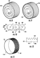
FIGS. 8-10 , thewave generator 103 may include a scallopedouter surface 801 androller bearings 901 which are arranged circumferentially and side-by-side about the scallopedouter surface 801 and which are respectively secured in placed by each corresponding scallop. That is, as shown inFIG. 10 , the scallopedouter surface 801 is formed of or includessequential ridges 802 and lands 803 where a sequential pair ofridges 802 and the interveningland 803 forms anindividual scallop 804 in which anindividual roller bearing 901 is rotatably disposable to rotate about a central longitudinal axis A thereof. In accordance with embodiments, adistal edge 1001 of eachridge 802 may be relatively sharp and may be radially aligned with or terminal within respective central longitudinal axes ofadjacent roller bearings 901. - While conventional flex splines are typically provided as a central flex spline part from which two inner rings extend and lateral flex spline parts that are fittable over exterior surfaces of the two inner rings, with reference to
FIGS. 11 and 12 , theflex spline 102 is formed as only a singleunitary piece 1101. As shown inFIG. 12 , this singleunitary piece 1101 includes abody 1201 that is integrally formed with a smooth interior diameter (ID)surface 1202 andexternal teeth 1203. Thesmooth ID surface 1202 is impinged upon by the roller bearings 901 (or by a bearing race) of theflex spline 102 as theflex spline 102 is rotated by thewave generator 103. As shown inFIG. 11 , thesmooth ID surface 1202 is continuous and without a seam or a break whereas, in accordance with embodiments, theexternal teeth 1203 may be formed to define one ormore machining slots 1102 which run circumferentially about theflex spline 102. Themachining slots 1102 may be produced as a result of the machining of theexternal teeth 1203 and are not specifically required. Where themachining slots 1102 are provided, however, they define groups of external teeth that may have similar or different numbers of external teeth. - In accordance with further embodiments and, with reference to
FIG. 13 , theflex spline 102 may include first and secondground flex splines output flex spline 1303 and acoupling 1304. The first and secondground flex splines output flex spline 1303. Thecoupling 1304 includes first ring gears 1305 that have internal teeth, second ring gears 1306 that have internal teeth and first and second sets ofcoupling pins - The respective IDs of the first and second
ground flex splines 1301 interface with therollers 901 of thewave generator 103. The first and secondground flex splines more ground arms 104 and the internal teeth of the first ring gears 1305. Theoutput flex spline 1303 has a second number of external teeth, which is different from the first number. These external teeth interface with an output gear, such as theoutput arm 105, and with the internal teeth of the second ring gears 1306. - The
flex spline 102 ofFIG. 13 has unique characteristics since theflex spline 102 needs to deform constantly due to the nature of the compound harmonic drive and since theflex spline 102 needs to transmit torque between the first and secondground flex splines output flex spline 1303. - Thus, in operation, the
wave generator 103 pushes the first and secondground flex splines flex spline 102. This strain results in cyclic stresses which can lead to fatigue and one method to reduce the stresses is to make theflex spline 102 relatively thin. While this would reduce the stress associated with the induced wave generator deformation, it reduces the ability of theflex spline 102 to transmit torque. Thecoupling 104 addresses this issues and makes it possible to transmit torque from the first and secondground flex splines flex spline 102 can be based on the stresses induced by deformation caused by the wave generator 103). - While the disclosure is provided in detail in connection with only a limited number of embodiments, it should be readily understood that the disclosure is not limited to such disclosed embodiments. Rather, the disclosure can be modified to incorporate any number of variations, alterations, substitutions or equivalent arrangements not heretofore described, but which are commensurate with the scope of the invention as defined by the claims. Additionally, while various embodiments of the disclosure have been described, it is to be understood that the exemplary embodiment(s) may include only some of the described exemplary aspects. Accordingly, the disclosure is not to be seen as limited by the foregoing description, but is only limited by the scope of the appended claims.
Claims (15)
- A compound harmonic actuator, comprising:a motor (101);a flex spline (102) disposed about the motor; anda wave generator (103) radially interposable between the motor and the flex spline and rotatably drivable by the motor and shaped to form the flex spline into an elliptical shape with an axis such that wave generator rotations drive rotations of the axis of the ellipse of the flex spline,the wave generator comprising a scalloped outer surface (801) and roller bearings (901) arranged circumferentially about the scalloped outer surface.
- The compound harmonic actuator according to claim 1, further comprising:a ground arm (104) in which the motor is supportively disposable; andan output arm (105) which is drivable by the flex spline to pivot within a predefined range of angles relative to the ground arm.
- The compound harmonic actuator according to claim 1 or 2, wherein the wave generator is shaped to form the flex spline into an irregular elliptical shape (301) with multiple major axes (302).
- The compound harmonic actuator according to any preceding claim, wherein the scalloped outer surface comprises sequential ridges (802) and lands (803).
- The compound harmonic actuator according to claim 4, wherein a distal edge of each ridge is sharp.
- The compound harmonic actuator according to claim 4 or 5, wherein a distal edge of each ridge is radially aligned with or terminal within respective central longitudinal axes of adjacent roller bearings.
- The compound harmonic actuator according to any preceding claim, wherein the flex spline is formed as only a single unitary piece (1101).
- The compound harmonic actuator according to any of claims 1 to 6, wherein the flex spline comprises:a ground flex spline (1301) configured to interface with the wave generator and having a first number of external teeth;an output flex spline (1303) configured to interface with an output gear and having a second number of external teeth which is different from the first number; anda coupling (1304) configured to interface with the respective first and second numbers of external teeth of the ground and output flex splines.
- A compound harmonic actuator, comprising:a motor (101);a flex spline (102) disposed about the motor; anda wave generator (103) radially interposable between the motor and the flex spline and rotatably drivable by the motor and shaped to form the flex spline into an elliptical shape with an axis such that wave generator rotations drive rotations of the axis of the ellipse of the flex spline,the flex spline comprising:a ground flex spline (1301) configured to interface with the wave generator and having a first number of external teeth;an output flex spline (1303) configured to interface with an output gear and having a second number of external teeth which is different from the first number; anda coupling (1304) configured to interface with the respective first and second numbers of external teeth of the ground and output flex splines.
- The compound harmonic actuator according to claim 9, further comprising:a ground arm (104) in which the motor is supportively disposable; andan output arm (105) which is drivable by the output flex spline to pivot within a predefined range of angles relative to the ground arm.
- The compound harmonic actuator according to claim 9, wherein the wave generator is shaped to form the flex spline into an irregular elliptical shape (301) with multiple major axes (302).
- The compound harmonic actuator according to claim 9, wherein the wave generator comprises a scalloped outer surface (801) and roller bearings (901) arranged circumferentially about the scalloped outer surface, wherein:the scalloped outer surface comprises sequential ridges (802) and lands (803),each roller bearing rolls about a central longitudinal axis thereof in a corresponding land.
- The compound harmonic actuator according to claim 9, wherein the coupling comprises:a first ring gear (1305) having internal teeth to interface with the first number of external teeth of the ground flex spline;a second ring gear (1306) having internal teeth to interface with the second number of external teeth of the output flex spline; andcoupling pins (1307) disposed to secure the first and second ring gears.
- The compound harmonic actuator according to claim 9, wherein the ground flex spline is provided as first and second ground flex splines on either side of the output flex spline.
- The compound harmonic actuator according to claim 14, wherein the coupling comprises:first ring gears that each have internal teeth to interface with the first number of external teeth of each of the first and second ground flex splines;second ring gears that each have internal teeth to interface with the second number of external teeth of the output flex spline; andfirst and second sets of coupling pins disposed to secure each of the first ring gears to one of the second ring gears.
Applications Claiming Priority (1)
| Application Number | Priority Date | Filing Date | Title |
|---|---|---|---|
| US15/644,388 US10883590B2 (en) | 2017-07-07 | 2017-07-07 | Compound harmonic gear |
Publications (3)
| Publication Number | Publication Date |
|---|---|
| EP3425777A2 true EP3425777A2 (en) | 2019-01-09 |
| EP3425777A3 EP3425777A3 (en) | 2019-05-08 |
| EP3425777B1 EP3425777B1 (en) | 2020-09-30 |
Family
ID=62116277
Family Applications (1)
| Application Number | Title | Priority Date | Filing Date |
|---|---|---|---|
| EP18170640.9A Active EP3425777B1 (en) | 2017-07-07 | 2018-05-03 | Compound harmonic gear |
Country Status (2)
| Country | Link |
|---|---|
| US (1) | US10883590B2 (en) |
| EP (1) | EP3425777B1 (en) |
Cited By (6)
| Publication number | Priority date | Publication date | Assignee | Title |
|---|---|---|---|---|
| CN113443153A (en) * | 2021-07-22 | 2021-09-28 | 成都浩孚科技有限公司 | Photoelectric pod transmission structure |
| EP3998207A1 (en) * | 2021-02-19 | 2022-05-18 | Lilium eAircraft GmbH | Aircraft |
| EP3998206A1 (en) * | 2021-02-19 | 2022-05-18 | Lilium eAircraft GmbH | Aircraft |
| EP4163518A1 (en) * | 2021-10-05 | 2023-04-12 | Hamilton Sundstrand Corporation | Hinge-line actuator for rotating an aircraft control surface |
| EP4390179A1 (en) * | 2022-12-23 | 2024-06-26 | Hamilton Sundstrand Corporation | Strain wave drive |
| EP4390178A1 (en) * | 2022-12-23 | 2024-06-26 | Hamilton Sundstrand Corporation | Strain wave drive |
Families Citing this family (7)
| Publication number | Priority date | Publication date | Assignee | Title |
|---|---|---|---|---|
| US11085518B2 (en) * | 2019-04-18 | 2021-08-10 | Hamilton Sunstrand Corporation | Inverted compound harmonic drive |
| US11519487B2 (en) * | 2019-08-16 | 2022-12-06 | Hamilton Sundstrand Corporation | Compound harmonic gear motor configured for continuous output rotation |
| JP7585096B2 (en) * | 2021-03-05 | 2024-11-18 | ナブテスコ株式会社 | Manufacturing method of a strain wave gear device |
| US12140213B2 (en) | 2021-08-11 | 2024-11-12 | Hamilton Sundstrand Corporation | Compound harmonic gear system with dual output arms |
| US12072009B2 (en) * | 2022-05-27 | 2024-08-27 | Hamilton Sundstrand Corporation | Harmonic gearset with split flexspline |
| EP4421352A1 (en) * | 2023-02-23 | 2024-08-28 | Hamilton Sundstrand Corporation | Flex spline for strain wave drive |
| EP4589173A1 (en) * | 2024-01-18 | 2025-07-23 | Goodrich Actuation Systems Limited | Strain wave drive bearing assembly |
Family Cites Families (23)
| Publication number | Priority date | Publication date | Assignee | Title |
|---|---|---|---|---|
| DE532053C (en) | 1926-06-01 | 1931-08-22 | Keenok Gears Ltd | Friction wheel or friction roller |
| US4003272A (en) * | 1975-01-31 | 1977-01-18 | Dmitry Pavlovich Volkov | Harmonic gear reduction unit |
| US4715247A (en) | 1985-09-26 | 1987-12-29 | Kabushiki Kaisha Toshiba | Transmission apparatus with reduced frictional force |
| JPH06103060B2 (en) | 1985-09-26 | 1994-12-14 | 株式会社東芝 | Elliptical orbit rolling bearing |
| US4934212A (en) | 1989-03-29 | 1990-06-19 | Quincy Technologies, Inc. | Harmonic drive flexspline manufacture |
| US5642645A (en) | 1995-09-25 | 1997-07-01 | Teijin Seiki Boston, Inc. | Hermetically sealed harmonic drive transmission manufacture |
| CN101427053B (en) | 2006-04-25 | 2012-04-04 | 纳博特斯克株式会社 | Rotation device |
| GB0618902D0 (en) | 2006-09-25 | 2006-11-01 | Airbus Uk Ltd | Actuator |
| JP4948479B2 (en) | 2008-06-26 | 2012-06-06 | 株式会社ハーモニック・ドライブ・システムズ | Compound wave gear reducer |
| US9605742B2 (en) | 2010-11-04 | 2017-03-28 | Panchien LIN | Large-ratio strain wave gearing speed changing apparatus |
| TWM441059U (en) | 2012-06-13 | 2012-11-11 | Harmonic Innovation Technology Co Ltd | Flexspline mounting structure of harmonic drive reducer |
| US9228651B2 (en) | 2013-03-05 | 2016-01-05 | Karem Aircraft, Inc. | Compact torque-transmitting gearbox with high reduction ratio |
| US9157517B2 (en) | 2013-09-16 | 2015-10-13 | Hamilton Sundstrand Corporation | Compound harmonic drive |
| US9360098B2 (en) | 2013-10-29 | 2016-06-07 | Roopnarine | Strain wave drive with improved performance |
| US9371899B2 (en) | 2014-05-27 | 2016-06-21 | Hamilton Sundstrand Corporation | Harmonic drive assembly with selective disconnect and reconnect |
| US9394984B2 (en) * | 2014-06-09 | 2016-07-19 | Hamilton Sundstrand Corporation | Three point harmonic drive |
| US9528587B2 (en) * | 2014-07-08 | 2016-12-27 | Hamilton Sundstrand Corporation | Harmonic drive and method of assembling |
| US20160229525A1 (en) * | 2014-09-10 | 2016-08-11 | Hamilton Sundstrand Corporation | Electromechanical rotary actuator |
| US9751617B2 (en) * | 2014-12-02 | 2017-09-05 | Hamilton Sundstrand Corporation | Multi-slice rotary electromechanical actuator |
| US9783262B2 (en) | 2015-04-07 | 2017-10-10 | Tangent Motor Company | Electric drive unit |
| US20160305528A1 (en) | 2015-04-20 | 2016-10-20 | Nabors Lux Finance 2 Sarl | Harmonic Gear Drive |
| US9915334B2 (en) | 2015-10-16 | 2018-03-13 | Hamilton Sundstrand Corporation | Flex spline for use with a compound harmonic generator |
| US10584782B2 (en) * | 2016-08-05 | 2020-03-10 | Hamilton Sundstrand Corporation | Joined flex spline for compound harmonic drive |
-
2017
- 2017-07-07 US US15/644,388 patent/US10883590B2/en active Active
-
2018
- 2018-05-03 EP EP18170640.9A patent/EP3425777B1/en active Active
Non-Patent Citations (1)
| Title |
|---|
| None |
Cited By (9)
| Publication number | Priority date | Publication date | Assignee | Title |
|---|---|---|---|---|
| EP3998207A1 (en) * | 2021-02-19 | 2022-05-18 | Lilium eAircraft GmbH | Aircraft |
| EP3998206A1 (en) * | 2021-02-19 | 2022-05-18 | Lilium eAircraft GmbH | Aircraft |
| WO2022175065A1 (en) * | 2021-02-19 | 2022-08-25 | Lilium Eaircraft Gmbh | Aircraft |
| US12589869B2 (en) | 2021-02-19 | 2026-03-31 | Archer Aviation Inc. | Aircraft |
| CN113443153A (en) * | 2021-07-22 | 2021-09-28 | 成都浩孚科技有限公司 | Photoelectric pod transmission structure |
| EP4163518A1 (en) * | 2021-10-05 | 2023-04-12 | Hamilton Sundstrand Corporation | Hinge-line actuator for rotating an aircraft control surface |
| EP4390179A1 (en) * | 2022-12-23 | 2024-06-26 | Hamilton Sundstrand Corporation | Strain wave drive |
| EP4390178A1 (en) * | 2022-12-23 | 2024-06-26 | Hamilton Sundstrand Corporation | Strain wave drive |
| US12313154B2 (en) | 2022-12-23 | 2025-05-27 | Hamilton Sundstrand Corporation | Strain wave drive |
Also Published As
| Publication number | Publication date |
|---|---|
| US10883590B2 (en) | 2021-01-05 |
| EP3425777A3 (en) | 2019-05-08 |
| EP3425777B1 (en) | 2020-09-30 |
| US20190011032A1 (en) | 2019-01-10 |
Similar Documents
| Publication | Publication Date | Title |
|---|---|---|
| EP3425777B1 (en) | Compound harmonic gear | |
| US9394984B2 (en) | Three point harmonic drive | |
| EP3279512B1 (en) | Joined flex spline for compound harmonic drive | |
| CA2889449C (en) | Harmonic drive assembly with selective disconnect and reconnect | |
| EP2615329A1 (en) | Speed reduction mechanism, and motor torque transmission device including the same | |
| EP3447886B1 (en) | Inverted harmonic gear actuator | |
| JP2017219122A (en) | Link actuator | |
| EP3470706B1 (en) | Method of developing spline profile | |
| EP2915744B1 (en) | Flight control actuator drive | |
| US8550950B2 (en) | Planetary reduction gearbox | |
| CN114483885B (en) | Coaxial double-output composite gear train speed reducer | |
| EP2730805A1 (en) | Reduction gear | |
| WO2026060835A1 (en) | Parallel high-efficiency composite flexspline-based internal-meshing harmonic transmission in motor rotor | |
| US20030129059A1 (en) | Mechanism for controlling independently the pitch of each of a plurality of blades of a wind turbine | |
| EP2837849A1 (en) | Wave gear mechanism | |
| CN113277051B (en) | Modularized cycloid propeller adopting gear synchronous kite-shaped mechanism | |
| CN114893541A (en) | Speed variator | |
| JP6632341B2 (en) | Wave gear device with traction drive mechanism | |
| CN206012958U (en) | A kind of unmanned plane rotor and unmanned plane | |
| CN224187986U (en) | Hard gear harmonic reducer | |
| JP7839060B2 (en) | Internal meshing gear system | |
| JPS6322160Y2 (en) | ||
| JP2026082072A (en) | Power transmission mechanism | |
| KR20190001554A (en) | Differential gearbox | |
| KR20150025165A (en) | Speed-reduction transmission bearing |
Legal Events
| Date | Code | Title | Description |
|---|---|---|---|
| PUAI | Public reference made under article 153(3) epc to a published international application that has entered the european phase |
Free format text: ORIGINAL CODE: 0009012 |
|
| STAA | Information on the status of an ep patent application or granted ep patent |
Free format text: STATUS: THE APPLICATION HAS BEEN PUBLISHED |
|
| AK | Designated contracting states |
Kind code of ref document: A2 Designated state(s): AL AT BE BG CH CY CZ DE DK EE ES FI FR GB GR HR HU IE IS IT LI LT LU LV MC MK MT NL NO PL PT RO RS SE SI SK SM TR |
|
| AX | Request for extension of the european patent |
Extension state: BA ME |
|
| PUAL | Search report despatched |
Free format text: ORIGINAL CODE: 0009013 |
|
| AK | Designated contracting states |
Kind code of ref document: A3 Designated state(s): AL AT BE BG CH CY CZ DE DK EE ES FI FR GB GR HR HU IE IS IT LI LT LU LV MC MK MT NL NO PL PT RO RS SE SI SK SM TR |
|
| AX | Request for extension of the european patent |
Extension state: BA ME |
|
| RIC1 | Information provided on ipc code assigned before grant |
Ipc: B64C 13/34 20060101ALI20190329BHEP Ipc: H02K 7/116 20060101AFI20190329BHEP Ipc: B64C 9/00 20060101ALI20190329BHEP Ipc: F16H 49/00 20060101ALI20190329BHEP |
|
| STAA | Information on the status of an ep patent application or granted ep patent |
Free format text: STATUS: REQUEST FOR EXAMINATION WAS MADE |
|
| 17P | Request for examination filed |
Effective date: 20191108 |
|
| RBV | Designated contracting states (corrected) |
Designated state(s): AL AT BE BG CH CY CZ DE DK EE ES FI FR GB GR HR HU IE IS IT LI LT LU LV MC MK MT NL NO PL PT RO RS SE SI SK SM TR |
|
| GRAP | Despatch of communication of intention to grant a patent |
Free format text: ORIGINAL CODE: EPIDOSNIGR1 |
|
| STAA | Information on the status of an ep patent application or granted ep patent |
Free format text: STATUS: GRANT OF PATENT IS INTENDED |
|
| INTG | Intention to grant announced |
Effective date: 20200424 |
|
| GRAS | Grant fee paid |
Free format text: ORIGINAL CODE: EPIDOSNIGR3 |
|
| GRAA | (expected) grant |
Free format text: ORIGINAL CODE: 0009210 |
|
| STAA | Information on the status of an ep patent application or granted ep patent |
Free format text: STATUS: THE PATENT HAS BEEN GRANTED |
|
| AK | Designated contracting states |
Kind code of ref document: B1 Designated state(s): AL AT BE BG CH CY CZ DE DK EE ES FI FR GB GR HR HU IE IS IT LI LT LU LV MC MK MT NL NO PL PT RO RS SE SI SK SM TR |
|
| REG | Reference to a national code |
Ref country code: CH Ref legal event code: EP Ref country code: GB Ref legal event code: FG4D |
|
| REG | Reference to a national code |
Ref country code: DE Ref legal event code: R096 Ref document number: 602018008206 Country of ref document: DE Ref country code: AT Ref legal event code: REF Ref document number: 1319814 Country of ref document: AT Kind code of ref document: T Effective date: 20201015 |
|
| REG | Reference to a national code |
Ref country code: IE Ref legal event code: FG4D |
|
| PG25 | Lapsed in a contracting state [announced via postgrant information from national office to epo] |
Ref country code: FI Free format text: LAPSE BECAUSE OF FAILURE TO SUBMIT A TRANSLATION OF THE DESCRIPTION OR TO PAY THE FEE WITHIN THE PRESCRIBED TIME-LIMIT Effective date: 20200930 Ref country code: GR Free format text: LAPSE BECAUSE OF FAILURE TO SUBMIT A TRANSLATION OF THE DESCRIPTION OR TO PAY THE FEE WITHIN THE PRESCRIBED TIME-LIMIT Effective date: 20201231 Ref country code: NO Free format text: LAPSE BECAUSE OF FAILURE TO SUBMIT A TRANSLATION OF THE DESCRIPTION OR TO PAY THE FEE WITHIN THE PRESCRIBED TIME-LIMIT Effective date: 20201230 Ref country code: SE Free format text: LAPSE BECAUSE OF FAILURE TO SUBMIT A TRANSLATION OF THE DESCRIPTION OR TO PAY THE FEE WITHIN THE PRESCRIBED TIME-LIMIT Effective date: 20200930 Ref country code: HR Free format text: LAPSE BECAUSE OF FAILURE TO SUBMIT A TRANSLATION OF THE DESCRIPTION OR TO PAY THE FEE WITHIN THE PRESCRIBED TIME-LIMIT Effective date: 20200930 Ref country code: BG Free format text: LAPSE BECAUSE OF FAILURE TO SUBMIT A TRANSLATION OF THE DESCRIPTION OR TO PAY THE FEE WITHIN THE PRESCRIBED TIME-LIMIT Effective date: 20201230 |
|
| REG | Reference to a national code |
Ref country code: AT Ref legal event code: MK05 Ref document number: 1319814 Country of ref document: AT Kind code of ref document: T Effective date: 20200930 |
|
| PG25 | Lapsed in a contracting state [announced via postgrant information from national office to epo] |
Ref country code: LV Free format text: LAPSE BECAUSE OF FAILURE TO SUBMIT A TRANSLATION OF THE DESCRIPTION OR TO PAY THE FEE WITHIN THE PRESCRIBED TIME-LIMIT Effective date: 20200930 Ref country code: RS Free format text: LAPSE BECAUSE OF FAILURE TO SUBMIT A TRANSLATION OF THE DESCRIPTION OR TO PAY THE FEE WITHIN THE PRESCRIBED TIME-LIMIT Effective date: 20200930 |
|
| REG | Reference to a national code |
Ref country code: NL Ref legal event code: MP Effective date: 20200930 |
|
| REG | Reference to a national code |
Ref country code: LT Ref legal event code: MG4D |
|
| PG25 | Lapsed in a contracting state [announced via postgrant information from national office to epo] |
Ref country code: EE Free format text: LAPSE BECAUSE OF FAILURE TO SUBMIT A TRANSLATION OF THE DESCRIPTION OR TO PAY THE FEE WITHIN THE PRESCRIBED TIME-LIMIT Effective date: 20200930 Ref country code: CZ Free format text: LAPSE BECAUSE OF FAILURE TO SUBMIT A TRANSLATION OF THE DESCRIPTION OR TO PAY THE FEE WITHIN THE PRESCRIBED TIME-LIMIT Effective date: 20200930 Ref country code: PT Free format text: LAPSE BECAUSE OF FAILURE TO SUBMIT A TRANSLATION OF THE DESCRIPTION OR TO PAY THE FEE WITHIN THE PRESCRIBED TIME-LIMIT Effective date: 20210201 Ref country code: RO Free format text: LAPSE BECAUSE OF FAILURE TO SUBMIT A TRANSLATION OF THE DESCRIPTION OR TO PAY THE FEE WITHIN THE PRESCRIBED TIME-LIMIT Effective date: 20200930 Ref country code: SM Free format text: LAPSE BECAUSE OF FAILURE TO SUBMIT A TRANSLATION OF THE DESCRIPTION OR TO PAY THE FEE WITHIN THE PRESCRIBED TIME-LIMIT Effective date: 20200930 Ref country code: LT Free format text: LAPSE BECAUSE OF FAILURE TO SUBMIT A TRANSLATION OF THE DESCRIPTION OR TO PAY THE FEE WITHIN THE PRESCRIBED TIME-LIMIT Effective date: 20200930 |
|
| PG25 | Lapsed in a contracting state [announced via postgrant information from national office to epo] |
Ref country code: ES Free format text: LAPSE BECAUSE OF FAILURE TO SUBMIT A TRANSLATION OF THE DESCRIPTION OR TO PAY THE FEE WITHIN THE PRESCRIBED TIME-LIMIT Effective date: 20200930 Ref country code: AL Free format text: LAPSE BECAUSE OF FAILURE TO SUBMIT A TRANSLATION OF THE DESCRIPTION OR TO PAY THE FEE WITHIN THE PRESCRIBED TIME-LIMIT Effective date: 20200930 Ref country code: AT Free format text: LAPSE BECAUSE OF FAILURE TO SUBMIT A TRANSLATION OF THE DESCRIPTION OR TO PAY THE FEE WITHIN THE PRESCRIBED TIME-LIMIT Effective date: 20200930 Ref country code: IS Free format text: LAPSE BECAUSE OF FAILURE TO SUBMIT A TRANSLATION OF THE DESCRIPTION OR TO PAY THE FEE WITHIN THE PRESCRIBED TIME-LIMIT Effective date: 20210130 Ref country code: PL Free format text: LAPSE BECAUSE OF FAILURE TO SUBMIT A TRANSLATION OF THE DESCRIPTION OR TO PAY THE FEE WITHIN THE PRESCRIBED TIME-LIMIT Effective date: 20200930 |
|
| PG25 | Lapsed in a contracting state [announced via postgrant information from national office to epo] |
Ref country code: SK Free format text: LAPSE BECAUSE OF FAILURE TO SUBMIT A TRANSLATION OF THE DESCRIPTION OR TO PAY THE FEE WITHIN THE PRESCRIBED TIME-LIMIT Effective date: 20200930 Ref country code: NL Free format text: LAPSE BECAUSE OF FAILURE TO SUBMIT A TRANSLATION OF THE DESCRIPTION OR TO PAY THE FEE WITHIN THE PRESCRIBED TIME-LIMIT Effective date: 20200930 |
|
| REG | Reference to a national code |
Ref country code: DE Ref legal event code: R097 Ref document number: 602018008206 Country of ref document: DE |
|
| PLBE | No opposition filed within time limit |
Free format text: ORIGINAL CODE: 0009261 |
|
| STAA | Information on the status of an ep patent application or granted ep patent |
Free format text: STATUS: NO OPPOSITION FILED WITHIN TIME LIMIT |
|
| PG25 | Lapsed in a contracting state [announced via postgrant information from national office to epo] |
Ref country code: DK Free format text: LAPSE BECAUSE OF FAILURE TO SUBMIT A TRANSLATION OF THE DESCRIPTION OR TO PAY THE FEE WITHIN THE PRESCRIBED TIME-LIMIT Effective date: 20200930 |
|
| 26N | No opposition filed |
Effective date: 20210701 |
|
| PG25 | Lapsed in a contracting state [announced via postgrant information from national office to epo] |
Ref country code: IT Free format text: LAPSE BECAUSE OF FAILURE TO SUBMIT A TRANSLATION OF THE DESCRIPTION OR TO PAY THE FEE WITHIN THE PRESCRIBED TIME-LIMIT Effective date: 20200930 |
|
| PG25 | Lapsed in a contracting state [announced via postgrant information from national office to epo] |
Ref country code: SI Free format text: LAPSE BECAUSE OF FAILURE TO SUBMIT A TRANSLATION OF THE DESCRIPTION OR TO PAY THE FEE WITHIN THE PRESCRIBED TIME-LIMIT Effective date: 20200930 |
|
| REG | Reference to a national code |
Ref country code: CH Ref legal event code: PL |
|
| PG25 | Lapsed in a contracting state [announced via postgrant information from national office to epo] |
Ref country code: MC Free format text: LAPSE BECAUSE OF FAILURE TO SUBMIT A TRANSLATION OF THE DESCRIPTION OR TO PAY THE FEE WITHIN THE PRESCRIBED TIME-LIMIT Effective date: 20200930 Ref country code: LU Free format text: LAPSE BECAUSE OF NON-PAYMENT OF DUE FEES Effective date: 20210503 Ref country code: LI Free format text: LAPSE BECAUSE OF NON-PAYMENT OF DUE FEES Effective date: 20210531 Ref country code: CH Free format text: LAPSE BECAUSE OF NON-PAYMENT OF DUE FEES Effective date: 20210531 |
|
| REG | Reference to a national code |
Ref country code: BE Ref legal event code: MM Effective date: 20210531 |
|
| PG25 | Lapsed in a contracting state [announced via postgrant information from national office to epo] |
Ref country code: IE Free format text: LAPSE BECAUSE OF NON-PAYMENT OF DUE FEES Effective date: 20210503 |
|
| PG25 | Lapsed in a contracting state [announced via postgrant information from national office to epo] |
Ref country code: IS Free format text: LAPSE BECAUSE OF FAILURE TO SUBMIT A TRANSLATION OF THE DESCRIPTION OR TO PAY THE FEE WITHIN THE PRESCRIBED TIME-LIMIT Effective date: 20210130 |
|
| PG25 | Lapsed in a contracting state [announced via postgrant information from national office to epo] |
Ref country code: BE Free format text: LAPSE BECAUSE OF NON-PAYMENT OF DUE FEES Effective date: 20210531 |
|
| P01 | Opt-out of the competence of the unified patent court (upc) registered |
Effective date: 20230522 |
|
| PG25 | Lapsed in a contracting state [announced via postgrant information from national office to epo] |
Ref country code: CY Free format text: LAPSE BECAUSE OF FAILURE TO SUBMIT A TRANSLATION OF THE DESCRIPTION OR TO PAY THE FEE WITHIN THE PRESCRIBED TIME-LIMIT Effective date: 20200930 |
|
| PG25 | Lapsed in a contracting state [announced via postgrant information from national office to epo] |
Ref country code: HU Free format text: LAPSE BECAUSE OF FAILURE TO SUBMIT A TRANSLATION OF THE DESCRIPTION OR TO PAY THE FEE WITHIN THE PRESCRIBED TIME-LIMIT; INVALID AB INITIO Effective date: 20180503 |
|
| PG25 | Lapsed in a contracting state [announced via postgrant information from national office to epo] |
Ref country code: MK Free format text: LAPSE BECAUSE OF FAILURE TO SUBMIT A TRANSLATION OF THE DESCRIPTION OR TO PAY THE FEE WITHIN THE PRESCRIBED TIME-LIMIT Effective date: 20200930 |
|
| PG25 | Lapsed in a contracting state [announced via postgrant information from national office to epo] |
Ref country code: MT Free format text: LAPSE BECAUSE OF FAILURE TO SUBMIT A TRANSLATION OF THE DESCRIPTION OR TO PAY THE FEE WITHIN THE PRESCRIBED TIME-LIMIT Effective date: 20200930 |
|
| PGFP | Annual fee paid to national office [announced via postgrant information from national office to epo] |
Ref country code: DE Payment date: 20250423 Year of fee payment: 8 |
|
| PGFP | Annual fee paid to national office [announced via postgrant information from national office to epo] |
Ref country code: GB Payment date: 20250423 Year of fee payment: 8 |
|
| PGFP | Annual fee paid to national office [announced via postgrant information from national office to epo] |
Ref country code: FR Payment date: 20250423 Year of fee payment: 8 |
|
| PG25 | Lapsed in a contracting state [announced via postgrant information from national office to epo] |
Ref country code: TR Free format text: LAPSE BECAUSE OF FAILURE TO SUBMIT A TRANSLATION OF THE DESCRIPTION OR TO PAY THE FEE WITHIN THE PRESCRIBED TIME-LIMIT Effective date: 20200930 |