EP3425468A1 - Method and systems for facilitaing user navigation among a plurality of operator workstation screens - Google Patents
Method and systems for facilitaing user navigation among a plurality of operator workstation screens Download PDFInfo
- Publication number
- EP3425468A1 EP3425468A1 EP17179844.0A EP17179844A EP3425468A1 EP 3425468 A1 EP3425468 A1 EP 3425468A1 EP 17179844 A EP17179844 A EP 17179844A EP 3425468 A1 EP3425468 A1 EP 3425468A1
- Authority
- EP
- European Patent Office
- Prior art keywords
- interest
- condition
- wearable
- screen
- operator workstation
- Prior art date
- Legal status (The legal status is an assumption and is not a legal conclusion. Google has not performed a legal analysis and makes no representation as to the accuracy of the status listed.)
- Granted
Links
- 238000000034 method Methods 0.000 title claims abstract description 46
- 238000012544 monitoring process Methods 0.000 claims abstract description 88
- 230000003190 augmentative effect Effects 0.000 claims abstract description 7
- 238000004519 manufacturing process Methods 0.000 claims description 15
- 238000012545 processing Methods 0.000 claims description 12
- 238000004590 computer program Methods 0.000 claims description 4
- FGUUSXIOTUKUDN-IBGZPJMESA-N C1(=CC=CC=C1)N1C2=C(NC([C@H](C1)NC=1OC(=NN=1)C1=CC=CC=C1)=O)C=CC=C2 Chemical compound C1(=CC=CC=C1)N1C2=C(NC([C@H](C1)NC=1OC(=NN=1)C1=CC=CC=C1)=O)C=CC=C2 FGUUSXIOTUKUDN-IBGZPJMESA-N 0.000 claims 1
- 230000002093 peripheral effect Effects 0.000 description 5
- 230000000007 visual effect Effects 0.000 description 5
- 238000004891 communication Methods 0.000 description 2
- 239000011521 glass Substances 0.000 description 2
- 239000003550 marker Substances 0.000 description 2
- 230000000116 mitigating effect Effects 0.000 description 2
- 238000012549 training Methods 0.000 description 2
- 230000002159 abnormal effect Effects 0.000 description 1
- 230000002411 adverse Effects 0.000 description 1
- 238000003491 array Methods 0.000 description 1
- 230000004397 blinking Effects 0.000 description 1
- 230000000694 effects Effects 0.000 description 1
- 238000005516 engineering process Methods 0.000 description 1
- 238000005259 measurement Methods 0.000 description 1
- 238000004886 process control Methods 0.000 description 1
- 230000004044 response Effects 0.000 description 1
- 238000001429 visible spectrum Methods 0.000 description 1
- 230000001755 vocal effect Effects 0.000 description 1
Images


Classifications
-
- G—PHYSICS
- G05—CONTROLLING; REGULATING
- G05B—CONTROL OR REGULATING SYSTEMS IN GENERAL; FUNCTIONAL ELEMENTS OF SUCH SYSTEMS; MONITORING OR TESTING ARRANGEMENTS FOR SUCH SYSTEMS OR ELEMENTS
- G05B23/00—Testing or monitoring of control systems or parts thereof
- G05B23/02—Electric testing or monitoring
- G05B23/0205—Electric testing or monitoring by means of a monitoring system capable of detecting and responding to faults
- G05B23/0259—Electric testing or monitoring by means of a monitoring system capable of detecting and responding to faults characterized by the response to fault detection
- G05B23/0267—Fault communication, e.g. human machine interface [HMI]
- G05B23/0272—Presentation of monitored results, e.g. selection of status reports to be displayed; Filtering information to the user
-
- G—PHYSICS
- G05—CONTROLLING; REGULATING
- G05B—CONTROL OR REGULATING SYSTEMS IN GENERAL; FUNCTIONAL ELEMENTS OF SUCH SYSTEMS; MONITORING OR TESTING ARRANGEMENTS FOR SUCH SYSTEMS OR ELEMENTS
- G05B23/00—Testing or monitoring of control systems or parts thereof
- G05B23/02—Electric testing or monitoring
- G05B23/0205—Electric testing or monitoring by means of a monitoring system capable of detecting and responding to faults
-
- G—PHYSICS
- G06—COMPUTING; CALCULATING OR COUNTING
- G06F—ELECTRIC DIGITAL DATA PROCESSING
- G06F3/00—Input arrangements for transferring data to be processed into a form capable of being handled by the computer; Output arrangements for transferring data from processing unit to output unit, e.g. interface arrangements
- G06F3/01—Input arrangements or combined input and output arrangements for interaction between user and computer
- G06F3/011—Arrangements for interaction with the human body, e.g. for user immersion in virtual reality
- G06F3/013—Eye tracking input arrangements
Abstract
Description
- The present disclosure relates to a method and systems for facilitating navigation among operator workstation screens in a control and monitoring system.
- In a control room of a plant, a typical operator workstation can comprise many operator workstation screens of different sizes and purposes. For example, a workstation including the ABB® 800xA system may comprise nine operator workstation screens of different sizes. It may be difficult for an operator to effectively navigate in all the screens in an efficient manner.
- There are several usability problems caused by having multiple operator workstation screens. For example, operators can often find it difficult to locate the mouse pointer on the screens. Another problem is that it is difficult to orient in process graphics that are shown on many screens. For instance, when an alarm appears, it may not be clear at which screen the operator should look to find information regarding the alarm and the alarm object.
- Similarly, in education processes operators in training might experience difficulties while learning the operator workspace system. They need to train on simulators and require help from experienced operators staying by their side to help them familiarise with the system.
- In view of the above, an object of the present disclosure is to provide a method and systems for solving or at least mitigating the above-discussed problems.
- There is hence according to a first aspect of the present disclosure provided a method of facilitating user navigation among a plurality of operator workstation screens of a control and monitoring system, wherein the method is performed by the control and monitoring system and comprises: determining a condition of interest, determining a workstation screen identifier identifying an operator workstation screen displaying the condition of interest as condition of interest graphics, and transmitting the workstation screen identifier to a first wearable augmented reality, AR, device to thereby initiate displaying an indication of a location of the operator workstation screen displaying the condition of interest graphics.
- The workstation screen identifier is sent to the first wearable AR device. The first wearable AR device may thus by means of AR indicate to an operator wearing the first wearable AR device on which operator workstation screen the condition of interest graphics is located. The operator may thereby promptly become aware of a condition of interest and the operator workstation screen on which the condition of interest graphics is being displayed. This allows the operator to quickly navigate to the condition of interest graphics and handle the underlying condition of interest, if so required. Moreover, it facilitates for an operator in training to become acquainted with the layout of for example process graphics commonly displayed by the plurality operator workstation screens.
- Moreover, since the first wearable AR device utilises AR to indicate the location of the condition of interest graphics to a user, the indication will remain personal. To this end, personnel in a control room other than the operator wearing the first wearable AR device will not be disturbed by the visual indication. In this manner, a plurality of operators could potentially share a large number of operator workstation screens, each operator wearing a respective wearable AR device and being presented with individual AR indications of importance only for the individual operator. Hence, tailor-made data presentation, which does not disturb other operators, can be provided. This may make monitoring and control of large industrial processes more efficient and any mitigating action may smoothly be provided.
- One embodiment comprises determining a condition of interest graphics location on the operator workstation screen displaying the condition of interest graphics, wherein the transmitting in step c) further includes transmitting the condition of interest graphics location.
- One embodiment comprises: receiving an object location request from the first wearable AR device concerning an object location among the operator workstation screens, wherein the determining of the condition of interest is based on the object location request and the condition of interest graphics marks the object location.
- The condition of interest is in this case associated with the object location request, and arises as a result of the received objection location request.
- One embodiment comprises determining the object location on the operator workstation screen, wherein the transmitting involves transmitting the object location.
- According to one embodiment the object is a mouse pointer or an alarm object. Hereto, a user may wish to locate for example the mouse pointer among the plurality of operator workstation screens, and thus instructs the first wearable AR device to find. The first wearable AR device hence sends the objection location request to the control and monitoring system, which as a result determines that a condition of interest has occurred. The condition of interest is thus in this case created by the user and in particular the object location request received by the control and monitoring system.
- According to one embodiment a first subset of the plurality of operator workstation screens form a first monitoring sector configured to display a first section of an industrial process, and a second subset of the plurality of operator workstation screens form a second monitoring sector configured to display a second section of the industrial process, wherein the condition of interest graphics is displayed on an operator workstation screen of the first monitoring sector and the first wearable AR device is associated with the first monitoring sector, wherein the transmitting further involves transmitting the workstation screen identifier to a second wearable AR device associated with the second monitoring sector.
- In a control room, there may for example be several operator workstations or islands, each being populated by a plurality of operator workstation screens. Each operator workstation may for example be dedicated to a certain part or section of an industrial process. Each operator workstation or island may be under the responsibility of a respective operator. Each operator workstation is part of the same control and monitoring system. The operator workstation screens of all of the operator workstations hence receive their data from the same control and monitoring system. Since the operator workstations are for monitoring and controlling a common main industrial process, the first section and the second section may influence each other. For example, a fault/alarm or trend in the first section may propagate to the second section.
- The first subset of operator workstation screens forming the first monitoring sector may be operator workstation screens of a first operator workstation or island. The second subset of operator workstation screens forming the second monitoring sector may be operator workstation screens of a second operator workstation or island.
- Due to the cross-communication concerning a condition of interest graphic relating to the first section to the second wearable AR device, an operator responsible for the second operator workstation may become aware of an upcoming potential problem at an early stage. This may allow the operator of the second operator workstation to take preparatory actions before the problem potentially propagates to the second section of the industrial process.
- According to one embodiment the determining of a condition of interest involves determining that a process variable value is above a predetermined threshold value, wherein the condition of interest is indicated on the operator workstation screen by displaying the condition of interest graphics.
- The condition of interest, which is underlying the condition of interest graphics may thus for example be determined based on the comparison of process variable values with respective predetermined threshold values. A process variable value which exceeds the corresponding predetermined threshold may be an indication of a trend, an alarm situation or another abnormal event which should be brought to the awareness of the operator by displaying a condition of interest graphics.
- One embodiment comprises determining based on the condition of interest a type of indication to be displayed by the first wearable AR device, wherein the transmitting involves transmitting the determined type of indication to be displayed to the first wearable AR device.
- The control and monitoring system may thus, depending on the type of condition of interest determined, determine how an indication is to be displayed by the first wearable AR device. The control and monitoring system may for example comprise a database with a plurality of different condition of interests, each being associated with a certain type of indication. From this database, the control and monitoring system may be configured to select the appropriate type of indication and transmit this together with the workstation screen identifier to the first wearable AR device. The first wearable AR device will in this manner know what icon, object and/or text to display on the AR screen.
- As an alternative to the above, the type of indication may be preselected by a user for example using the first wearable AR device or by means of the control and monitoring system. As yet another alternative, when an object location request is transmitted by the first wearable AR device, the type of indication may be determined by the first wearable AR device based on the type of object that user requests the location of.
- In one variation, the control and monitoring system may also transmit the condition of interest if the condition of interest is obtained based on a process variable value exceeding a predetermined threshold. The first wearable AR device may in this variation be able to determine what type of indication to display on the AR screen.
- There is according to a second aspect of the present disclosure provided a computer program comprising computer code which when executed by processing circuitry of a control and monitoring system causes the control and monitoring system to perform the steps of the method according to the first aspect.
- There is according to a third aspect of the present disclosure provided a computer program product comprising a storage medium having computer program according to the second aspect stored thereon.
- There is according to a fourth aspect of the present disclosure provided a control and monitoring system comprising: a plurality of operator workstation screens, a storage medium comprising computer code, and processing circuitry which when executing the computer code causes the control and monitoring system to perform the steps of the method according to the first aspect.
- There is according to a fifth aspect of the present disclosure provided an augmented reality, AR, system comprising: the control and monitoring system according to the fourth aspect, and a first wearable AR device comprising an AR screen, the first wearable AR device being configured to wirelessly communicate with the control and monitoring system.
- According to one embodiment the first wearable AR device is configured to transmit an object location request to the control and monitoring system.
- According to one embodiment each operator workstation screen is provided with a screen identifying element identifying the operator workstation screen, wherein the first wearable AR device is configured to identify the operator workstation screen displaying the condition of interest graphics based on the workstation screen identifier received from the control and monitoring system and the corresponding screen identifying element, and wherein the first wearable AR device is configured to indicate on the AR screen the location of the operator workstation screen displaying the condition of interest graphics based on the screen identifying element to make the user aware of the condition of interest graphics.
- The screen identifying element may for example be a visual marker. An example of a visual marker is a quick response (QR)-code. Each screen identifying element may be arranged on a corner of an operator workstation screen. For example, each corner of an operator workstation screen may be provided with a screen identifying element. The size of the operator workstation screen and its position in the coordinate system of the first wearable AR device may thus be determined by reading the QR-codes. Alternatively, a single screen identifying element may contain size information and its corner location among the four corners, in which case only one screen identifying element may be provided for each operator workstation screen.
- The screen identifying element can instead of QR-codes for example be an infrared (IR) transmitter. The IR signal sent by the IR transmitter may in this case contain the corresponding information as a QR-code, such as screen identifying element location and/or size of the corresponding operator workstation screen. Other near-field communication technologies could alternatively be used, for example Bluetooth.
- According to one embodiment the first wearable AR device comprises a gaze detector configured to determine a gaze direction of a user of the first wearable AR device, wherein the first wearable AR device is configured to indicate on the AR screen the location of the operator workstation screen displaying the condition of interest graphics further based on the gaze direction.
- According to one embodiment the first wearable AR device is configured to display an indication of the operator workstation screen on the AR screen which corresponds to a mid or far peripheral field of the user. The indication will hence not be displayed in the central or near peripheral field, and will thus not obstruct any objects that the user may currently be focusing on.
- The indication may for example blink or move, especially if displayed in a mid or far peripheral field. This may ensure that the user notices the indication.
- The indication may for example include an arrow which points towards or onto the operator workstation screen of interest, i.e. the one displaying the condition of interest graphics and/or other object such as a mouse pointer.
- According to one embodiment the first wearable AR device is configured to display an icon or text in addition to the indication about the location of the condition of interest graphics or other object. This icon or text may for example provide information about the condition of interest graphics. Hence, for example, the indication may be an arrow, and the icon or text may provide information concerning the condition of interest graphics towards which the arrow points. The user may thus be able to, based on priority, determine whether to continue with current work or shift focus towards the condition of interest graphics.
- There is according to a sixth aspect provided a use of a first wearable augmented reality, AR, wearable in an AR system according to the fifth aspect.
- Generally, all terms used in the claims are to be interpreted according to their ordinary meaning in the technical field, unless explicitly defined otherwise herein. All references to "a/an/the element, apparatus, component, means, etc. are to be interpreted openly as referring to at least one instance of the element, apparatus, component, means, etc., unless explicitly stated otherwise. Moreover, any step in a method need not necessarily have to be carried out in the presented order, unless explicitly stated otherwise.
- The specific embodiments of the inventive concept will now be described, by way of example, with reference to the accompanying drawings, in which:
-
Fig. 1 schematically shows a control and monitoring system including a perspective view of a operator workstation; -
Fig. 2 schematically shows a wearable AR device; -
Fig. 3 schematically shows an example of an AR system including the control and monitoring system inFig. 1 and the wearable AR device inFig. 2 ; -
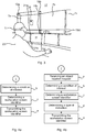
Figs 4a-c are flowcharts of methods of facilitating navigation among a plurality of operator workstation screens; -
Figs 5a and 5b shows examples of views through an AR screen of the wearable AR device; -
Figs 6a and 6b show examples of views through an AR screen of the wearable AR device; -
Fig. 7 shows an example of an operator using a shift report button; and -
Fig. 8 schematically depicts a control room provided with several operator workstations. - The inventive concept will now be described more fully hereinafter with reference to the accompanying drawings, in which exemplifying embodiments are shown. The inventive concept may, however, be embodied in many different forms and should not be construed as limited to the embodiments set forth herein; rather, these embodiments are provided by way of example so that this disclosure will be thorough and complete, and will fully convey the scope of the inventive concept to those skilled in the art. Like numbers refer to like elements throughout the description.
-
Fig. 1 depicts a control andmonitoring system 1. The exemplified control andmonitoring system 1 is a process control and monitoring control system configured to monitor and control an industrial process or a portion thereof. - The control and
monitoring system 1 comprises processing circuitry 3 and a storage medium 5. The storage medium 5 comprises computer code which when executed by the processing circuitry 3 causes the control andmonitoring system 1 to perform the methods disclosed herein. - The processing circuitry 3 uses any combination of one or more of a suitable central processing unit (CPU), multiprocessor, microcontroller, programmable logic controller (PLC), digital signal processor (DSP), application specific integrated circuit (ASIC), field programmable gate arrays (FPGA) etc., capable of executing any herein disclosed operations concerning navigation among a plurality of operator workstation screens.
- The storage medium 5 may for example be embodied as a memory, such as a random access memory (RAM), a read-only memory (ROM), an erasable programmable read-only memory (EPROM), or an electrically erasable programmable read-only memory (EEPROM) and more particularly as a non-volatile storage medium of a device in an external memory such as a USB (Universal Serial Bus) memory or a Flash memory, such as a compact Flash memory.
- The control and
monitoring system 1 also comprises a plurality ofoperator workstation screens 7a-7i. Theoperator workstation screens 7a-7i are configured to communicate with the processing circuitry 3. Theoperator workstation screens 7a-7i are configured to display process graphics. Eachoperator workstation 7a-7i may be configured to display distinct process graphics with respect to the process graphics displayed on the otheroperator workstation screens 7a-7i. The process graphics are related to the underlying industrial process (not shown inFig. 1 ) which the control andmonitoring system 1 is configured to monitor and control. - The operator workstations screens 7a-7i form part of an
operator workstation 7. Theoperator workstation 7 may for example include adesk 9 onto which theoperator workstation screens 7a-7i are mounted. A single operator may have as working task to monitor all of theoperator workstation screens 7a-7i of theoperator workstation 7. -
Fig. 2 shows an example of awearable AR device 11 configured to wirelessly communicate with the control andmonitoring system 1. Thewearable AR device 11 is adapted to be worn by a user. Thewearable AR device 11 comprises anAR screen 13. TheAR screen 13 is transparent in the visible spectrum. A user is thus able to see through theAR screen 13. Thewearable AR device 11 is configured to project AR onto theAR screen 13. - The
wearable AR device 11 may also comprise agaze detector 15. Thegaze detector 15 is configured to determine the gaze direction of a user wearing thewearable AR device 11. - The
wearable AR device 11 may according to one variation comprise a microphone configured to record user voice commands. According to one variation, thewearable AR device 11 may also comprise speakers to provide voice instructions or other types of sound to a user. These examples will be elaborated upon in the following. - The
wearable AR device 11 may also comprise wearable device processing circuitry. The wearable device processing circuitry may be configured to determine object locations displayed onoperator workstation screens 7a-7i in the coordinate system of thewearable AR device 11, to display AR in specific locations on theAR screen 13, to determine the gaze direction of a user, and to determine the spatial location of thewearable AR device 11 in the coordinate system of thewearable AR device 11. If audio is involved, e.g. voice commands and/or speakers, the wearable device processing circuitry may be configured to perform these instructions too. - The exemplified
wearable AR device 11 comprises AR glasses and theAR screen 13 is a visor. One example of suitable AR glasses is the Microsoft® HoloLens. Other wearable devices which are able to provide AR on a screen before the eyes of a user are also envisaged. For instance, another example of a wearable AR device is an AR contact lens. - Turning now to
Figs 3 and4a-c an example of anAR system 17 and the operation thereof in two example situations will now be described. TheAR system 17 comprises the control andmonitoring system 1 and thewearable AR device 11. Eachoperator workstation screen 7a-7i is provided with a plurality of screen identifying elements. The screen identifying elements may be visible passive screen identifying elements or active screen identifying elements. In the present example, each operator workstation screen is provided with fourscreen identifying elements 19a-19d, 21a-21d. For example, a firstoperator workstation screen 7a hasscreen identifying elements 19a-19c provided on its corners. The fourth screen identifying element of the firstoperator workstation screen 7a is not shown. A secondoperator workstation screen 7f is provided with fourscreen identifying elements 21a-21d and so on. - The control and
monitoring system 1 is configured to in a step b) determine when a condition of interest occurs. A condition of interest may for example be a condition in the underlying industrial process and may for example be a trend that may lead to an adverse condition or an alarm. In general, a condition of interest is a condition which should be brought to the attention of the operator or a condition caused by the user as a result of an object location request received by the control andmonitoring system 1. - The control and
monitoring system 1 is configured to receive measurements and/or estimations of process variables in the form of process variable values. The control andmonitoring system 1 may be configured to determine whether a condition of interest has occurred based on the continuously received process variable values. For example, the control andmonitoring system 1 may be configured to determine that a condition of interest has occurred if a process variable value is above a predetermined threshold value. - The control and
monitoring system 1 is configured to display a detected condition of interest, if a process variable value is above a predetermined threshold value, in the form of condition of interest graphics on an appropriateoperator workstation screen 7a-7i of the plurality ofoperator workstation screens 7a-7i, e.g. anoperator workstation screen 7a-7i which has process graphics associated with the condition of interest. - An
operator 23 seated at the operator workstation and monitoring the operator screens 7a-7i wears thewearable AR device 11 and monitors theoperator workstation screens 7a-7i through thewearable AR device 11. - In a first example situation, in the event that a condition of interest is detected by the control and
monitoring system 1, due to a process variable value exceeding the corresponding predetermined threshold value, and displayed as condition of interest graphics on one of theoperator workstation screens 7a-7i, the control andmonitoring system 1 is configured to in a step c) determine a workstation screen identifier identifying theoperator workstation screen 7a-7i on which the condition of interest graphics is being displayed. In the present example a condition ofinterest graphics 25 is displayed on the firstoperator workstation screen 7a. The control andmonitoring system 1 is configured to in a step e) transmit the workstation screen identifier identifying the operator workstation screen which displays the condition ofinterest graphics 25. In this example, the control andmonitoring system 1 hence transmits the workstation screen identifier of the firstoperator workstation screen 7a to thewearable AR device 11. - The
wearable AR device 11 is configured to receive the workstation screen identifier in a step B) and uses thescreen identifying elements 19a-19c to match with the workstation screen identifier to thereby identify the firstoperator workstation screen 7a. Thescreen identifying elements 19a-19c provide a measure of the size of the firstoperator workstation screen 7a, and of its distance from thewearable AR device 11. Thewearable AR device 11 is configured to locate the firstoperator workstation screen 7a in the coordinate system of thewearable AR device 11. - When the above operations have been performed, the
wearable AR device 11 is configured to display in a step C) anindication 27 on theAR screen 13 about the location of the condition ofinterest graphics 25, as shown inFig. 5a . Thisindication 27 may for example include an arrow pointing in the direction of the firstoperator workstation screen 7a. Theindication 27 could also or alternatively include a highlighting of the target operator workstation screen, in this example the firstoperator workstation screen 7a. - The control and
monitoring system 1 may be configured to determine the condition of interest graphics location on theoperator workstation screen 7a. The control andmonitoring system 1 can in this case transmit the condition of interest graphics location to thewearable AR device 11 in step e). The condition of interest graphics location may for example be the coordinates of the condition ofinterest graphics 25 in the coordinate system of the control andmonitoring system 1. - The
wearable AR device 11 is configured to receive the condition of interest graphics location and to transform the coordinates to the coordinate system of thewearable AR device 11. This may be performed by first determining the coordinates of the target operator workstation screen, in this case the firstoperator workstation screen 7a. With knowledge of the coordinates of the target operator workstation screen, the condition of interest location can be determined in the coordinate system of thewearable AR device 11. In this case, theindication 27 could alternatively or additionally include a highlighting of an area identifying the location of the condition ofinterest graphics 25 on the targetoperator workstation screen 7a, as shown inFig. 5b . - In one variation, the
wearable AR device 11 is configured to provide vocal instructions of the location of the condition ofinterest graphics 25. For example, thewearable AR device 11 could instruct the user to "look to your left" or "look to your right" to notify the user of a condition of interest and the location of the condition ofinterest graphics 25. - In a second example situation, the user may instruct the
wearable AR device 11 to show the location of a certain object displayed on anoperator workstation screen 7a-7i. The user may for example provide the instructions by means of voice commands and/or by means of gestures. Thewearable AR device 11 is configured to in a step A) send an object location request concerning the location of the object to the control andmonitoring system 1. The control andmonitoring system 1 is configured to receive the objection location request in a step a). The control andmonitoring system 1 is again configured to in step b) determine a condition of interest. In this case the condition of interest is determined based on the object location request. In particular, it can be said that the condition of interest occurs as a result of the object location request. The condition of interest graphics is in this case a graphical display of the object that the user desires to obtain the location of. Contrary to the first example situation described above, where a process variable value exceeds a corresponding predetermined threshold value causing a condition of interest, the condition of interest graphics is in this example typically already displayed on one of theoperator workstation screens 7a-7i when the object location request is received. This object may for example be the mouse pointer or an alarm object. The control andmonitoring system 1 determines in step c) the workstation screen identifier of theoperator workstation screen 7a-7i which currently displays the requested object. The control andmonitoring system 1 is configured to transmit the workstation screen identifier displaying the object to thewearable AR device 11 in step e). In a similar manner as has been described above, thewearable AR device 11 will perform step B), locate the target operator workstation screen and in step C) display a visual indication on theAR screen 13 of thewearable AR device 11 concerning the location of the object among the plurality ofoperator workstation screens 7a-7i. - Additionally, the control and
monitoring system 1 may be configured to determine and transmit the object location for example as coordinates in the coordinate system of the control andmonitoring system 1 to thewearable AR device 11. Thewearable AR device 11 is configured to determine the object location in the coordinate system of thewearable AR device 11. - The
wearable AR device 11 may according to one variation be configured to monitor the gaze direction of the user and to provide an indication to the user concerning condition of interest graphics displayed on one of the operator workstation screens in case the gaze direction differs from that of the condition of interest graphics for longer than a predetermined amount of time. In this manner, the AR system may ensure that a user eventually will notice the condition of interest graphics being displayed. - Furthermore, according to one variation, the control and
monitoring system 1 may in a step d) be configured to determine, based on the condition of interest determined in step b) a type of indication to be displayed by thewearable AR device 11. In this case, the transmitting in step e) involves transmitting the determined type of indication to be displayed to thewearable AR device 11. The type of indication may for instance be determined from e.g. a list in a database where each type of condition of interest may be associated with a type of indication. Thewearable AR device 11 will thus display anindication 27 according to the type of indication received from the control andmonitoring system 1. - Turning now to
Fig. 6a an example of how thevisual indication 27 can be displayed on theAR screen 13 is shown. Thewearable AR device 11 may for example be configured to display theindication 27 in a mid or far peripheral field of the user instead of the near peripheral or central field of vision. This ensures that the user will not be disturbed if focusing on an important issue on one of the operator workstation screens when theindication 27 appears. Theindication 27 may in this case be blinking and/or moving to ensure that the user notices theindication 27. -
Fig. 6b shows another example of theindication 27. In this example, theindication 27 is supplemented with an icon or text which provides information about the condition of interest graphics. In the example inFig. 5b , a text reading "Alarm" is displayed concurrently with the arrow. The operator is thus provided with information which allows the operator to prioritise whether to essentially instantly attend to matters relating to the condition of interest graphics. -
Fig. 7 shows theAR system 17 further including ashift report button 29. Theshift report button 29 is integrated with the control andmonitoring system 1 and thewearable AR device 11. Theshift report button 29 is used for taking screen shots or videos of all theoperator workstation screens 7a-7i when a condition of interest occurs during a shift. The screen shot(s) and video(s) are saved on the storage medium 5. When an operator shift takes place, the new operator will wear thewearable AR device 11. As an alternative to theshift report button 29 this functionality could be implemented in thewearable AR device 11 for example by performing a certain gesture and/or voice command to record screenshots or videos. - In the example shown in
Fig. 7 , the operator is presented with information on theAR screen 13 concerning events which occurred and where recorded during the previous shift. The events are presented as icons and/ortext 31a-31c with information about when the screenshot or video was taken and by whom. The icons and/ortext 31a-31c may additionally contain notes made by the operator of the previous shift. The note(s) may include text, a photo, a video or a voice message. The operator who is just commencing a shift will thus be able to view the screen shots and/or videos by selecting the icons and/ortext 31a-31c. The selection may for example be provided by means of gestures by the operator. The icons and/ortext 31a-31c may be displayed around the operator workstation screens so as not to obstruct them. This can be achieved because thewearable AR device 11 is configured to determine the location of all of theoperator workstation screens 7a-7i using the screen identifying elements. The user may then, for example, drag an icon/text 31a-31c to one of the operator workstation displays and drop it to display the associated screenshots or video on all of theoperator workstation screens 7a-7i, as initially seen by the operator who captured the condition of interest in a previous shift. - There may also be displayed generic information about previous shifts such as statistics from previous shift over previous operator activities, performance, level of alarms, amount of acknowledged alarms, etc.
-
Fig. 8 shows an example of acontrol room 33 containing a plurality of operator workstations.Control room 33 contains afirst operator workstation 7 and asecond operator workstation 35. Bothoperator workstations monitoring system 1. Thefirst operator workstation 7 comprises a first subset ofoperator workstation screens 7a-7i forming a first monitoring sector configured to display a first section of an industrial process. Thesecond operator workstation 35 comprises a second subset ofoperator workstation screens 35a-35i configured to display a second section of an industrial process. The first subset ofoperator workstation screens 7a-7i and the second subset ofoperator workstation screens 35a-35i hence typically display completely different process graphics, related to the respective section of the industrial process. - The
first operator workstation 7 may be under the responsibility of afirst operator 23 wearing a firstwearable AR device 11 and thesecond operator workstation 35 may be under the responsibility of asecond operator 37 wearing a secondwearable AR device 12 identical in operation to the firstwearable AR device 11. The firstwearable AR device 11 is configured to be used with thefirst control section 7 and the secondwearable AR device 12 is configured to be used with thesecond control section 35. Hereto, the firstwearable AR device 11 typically only communicates with the control andmonitoring system 1 concerning objects in the process graphics shown on the first subset ofoperator workstation screens 7a-7i. The secondwearable AR device 12 typically only communicates with the control andmonitoring system 1 concerning objects in the process graphics shown on the second subset ofoperator workstation screens 35a-35i. However, a condition of interest and the displayed condition of interest graphics may occur on one of the operator workstation screens of one of the twooperator workstations other operator workstation operator workstation display 7a-7i, this condition of interest graphics may be of relevance for thesecond operator 37 too. The control andmonitoring system 1 may thus be configured to transmit the workstation screen identifier of anoperator workstation screen 7a-7i displaying the condition of interest graphics to the secondwearable AR device 12 too, as shown by the dashed arrow. This may ensure that thesecond operator 37 becomes aware of a condition of interest before a condition of interest resulting from the condition of interest in the first section has also become a condition of interest in the second section and thus being displayed as condition of interest graphics on one of theoperator workstation displays 35a-35i of thesecond operator workstation 35. - The control and
monitoring system 1 may be configured to select when a condition of interest is to be reported to the secondwearable device 12 and vice versa. The control andmonitoring system 1 may for example contain a database with information about conditions of interests and how they affect different sections of the industrial process. - The inventive concept has mainly been described above with reference to a few examples. However, as is readily appreciated by a person skilled in the art, other embodiments than the ones disclosed above are equally possible within the scope of the inventive concept, as defined by the appended claims.
Claims (15)
- A method of facilitating user navigation among a plurality of operator workstation screens (7a-7i, 9a-9i) of a control and monitoring system (1), wherein the method is performed by the control and monitoring system (1) and comprises:determining (b) a condition of interest,determining (c) a workstation screen identifier identifying an operator workstation screen (7a-7i, 9a-9i) displaying the condition of interest as condition of interest graphics (25), andtransmitting (e) the workstation screen identifier to a first wearable augmented reality, AR, device (11) to thereby initiate displaying an indication (27) of a location of the operator workstation screen (7a-7i, 9a-9i) displaying the condition of interest graphics (25).
- The method as claimed in claim 1, comprising determining a condition of interest graphics location on the operator workstation screen (7a-7i, 9a-9i) displaying the condition of interest graphics (25), wherein the transmitting (c) further includes transmitting the condition of interest graphics location.
- The method as claimed in claim 1 or 2, comprising:receiving (a) an object location request from the first wearable AR device (11) concerning an object location among the operator workstation screens (7a-7i), wherein the determining (b) of the condition of interest is based on the object location request and the condition of interest graphics marks the object location.
- The method as claimed in claim 3, comprising determining the object location on the operator workstation screen (7a-7i, 9a-9i), wherein the transmitting in step f) involves transmitting the object location.
- The method as claimed in claim 3 or 4, wherein the object is a mouse pointer or an alarm object.
- The method as claimed any of the preceding claims, wherein a first subset (7a-7i) of the plurality of operator workstation screens (7a-7i, 9a-9i) form a first monitoring sector configured to display a first section of an industrial process, and a second subset (9a-9i) of the plurality of operator workstation screens (7a-7i, 9a-9i) form a second monitoring sector configured to display a second section of the industrial process, wherein the condition of interest graphics (25) is displayed on an operator workstation screen of the first monitoring sector and the first wearable AR device (11) is associated with the first monitoring sector, wherein the transmitting further involves transmitting the workstation screen identifier to a second wearable AR device (12) associated with the second monitoring sector.
- The method as claimed in any of the preceding claims, wherein the determining (a) of a condition of interest involves determining that a process variable value is above a predetermined threshold value, wherein the condition of interest is indicated on the operator workstation screen (7a-7i, 9a-9i) by displaying the condition of interest graphics (25).
- The method as claimed in any of the preceding claims, comprising determining (d) based on the condition of interest a type of indication to be displayed by the first wearable AR device (11), wherein the transmitting (e) involves transmitting the determined type of indication to be displayed to the first wearable AR device (11).
- A computer program comprising computer code which when executed by processing circuitry (3) of a control and monitoring system (1) causes the control and monitoring system (1) to perform the steps of the method as claimed in any of claims 1-8.
- A control and monitoring system (1) comprising:a plurality of operator workstation screens (7a-7i, 9a-9i),a storage medium (5) comprising computer code, andprocessing circuitry (3) which when executing the computer code causes the control and monitoring system (1) to perform the steps of the method as claimed in any of claims 1-7.
- An augmented reality, AR, system (17) comprising:the control and monitoring system (1) as claimed in claim 10, anda first wearable AR device (11) comprising an AR screen (13), the first wearable AR device (11) being configured to wirelessly communicate with the control and monitoring system (1).
- The AR system (17) as claimed in claim 11, wherein the first wearable AR device (11) is configured to transmit an object location request to the control and monitoring system (1).
- The AR system (17) as claimed in claim 11 or 12, wherein each operator workstation screen (7a-7i, 9a-9i) is provided with a screen identifying element (19a-21c, 21a-21d) identifying the operator workstation screen (7a-7i, 9a-9i), wherein the first wearable AR device (11) is configured to identify the operator workstation screen (7a-7i, 9a-9i) displaying the condition of interest graphics (25) based on the workstation screen identifier received from the control and monitoring system (1) and the corresponding screen identifying element (19a-19c, 21a-21d), and wherein the first wearable AR device (11) is configured to indicate on the AR screen (13) the location of the operator workstation screen (7a-7i, 9a-9i) displaying the condition of interest graphics (25) based on the screen identifying element to make the user aware of the condition of interest graphics.
- The AR system (17) as claimed in claim 13, wherein the first wearable AR device (11) comprises a gaze detector (15) configured to determine a gaze direction of a user of the first wearable AR device (11), wherein the first wearable AR device (11) is configured to indicate on the AR screen (13) the location of the operator workstation screen (7a-7i, 9a-9i) displaying the condition of interest graphics (25) further based on the gaze direction.
- Use of a first wearable augmented reality, AR, wearable (11) in an AR system (17) as claimed in any of claims 11-14.
Priority Applications (4)
| Application Number | Priority Date | Filing Date | Title |
|---|---|---|---|
| EP17179844.0A EP3425468B1 (en) | 2017-07-05 | 2017-07-05 | Method and systems for facilitaing user navigation among a plurality of operator workstation screens |
| CN201880042957.9A CN110799916B (en) | 2017-07-05 | 2018-05-30 | Method and system for facilitating user navigation among multiple operator workstation screens |
| PCT/EP2018/064183 WO2019007592A1 (en) | 2017-07-05 | 2018-05-30 | Method and systems for facilitating user navigation among a plurality of operator workstation screens |
| US16/627,535 US20200125081A1 (en) | 2017-07-05 | 2018-05-30 | Method And Systems For Facilitating User Navigation Among A Plurality Of Operator Workstation Screens |
Applications Claiming Priority (1)
| Application Number | Priority Date | Filing Date | Title |
|---|---|---|---|
| EP17179844.0A EP3425468B1 (en) | 2017-07-05 | 2017-07-05 | Method and systems for facilitaing user navigation among a plurality of operator workstation screens |
Publications (2)
| Publication Number | Publication Date |
|---|---|
| EP3425468A1 true EP3425468A1 (en) | 2019-01-09 |
| EP3425468B1 EP3425468B1 (en) | 2021-09-01 |
Family
ID=59399221
Family Applications (1)
| Application Number | Title | Priority Date | Filing Date |
|---|---|---|---|
| EP17179844.0A Active EP3425468B1 (en) | 2017-07-05 | 2017-07-05 | Method and systems for facilitaing user navigation among a plurality of operator workstation screens |
Country Status (4)
| Country | Link |
|---|---|
| US (1) | US20200125081A1 (en) |
| EP (1) | EP3425468B1 (en) |
| CN (1) | CN110799916B (en) |
| WO (1) | WO2019007592A1 (en) |
Cited By (1)
| Publication number | Priority date | Publication date | Assignee | Title |
|---|---|---|---|---|
| WO2020156636A1 (en) * | 2019-01-29 | 2020-08-06 | Abb Schweiz Ag | Method and systems for facilitating operator concentration on one among a plurality of operator workstation screens |
Families Citing this family (1)
| Publication number | Priority date | Publication date | Assignee | Title |
|---|---|---|---|---|
| EP4329293A1 (en) * | 2022-08-25 | 2024-02-28 | Artificialy SA | Support system of the control of surveillance cameras |
Citations (2)
| Publication number | Priority date | Publication date | Assignee | Title |
|---|---|---|---|---|
| WO2012084041A1 (en) * | 2010-12-22 | 2012-06-28 | Abb Research Ltd | Method and system for monitoring an industrial system involving an eye tracking system |
| WO2013123991A1 (en) * | 2012-02-23 | 2013-08-29 | Abb Research Ltd | A method for providing a navigation tool of a user interface for an industrial control system |
Family Cites Families (5)
| Publication number | Priority date | Publication date | Assignee | Title |
|---|---|---|---|---|
| JP2003050630A (en) * | 2001-08-08 | 2003-02-21 | Mitsubishi Electric Corp | Plant operation supporting system |
| US9581993B2 (en) * | 2014-02-11 | 2017-02-28 | Honeywell International Inc. | Ambient display for industrial operator consoles |
| US20160004393A1 (en) * | 2014-07-01 | 2016-01-07 | Google Inc. | Wearable device user interface control |
| FR3032544B1 (en) * | 2015-02-05 | 2018-03-09 | Schneider Electric Industries Sas | DISPLAY MANAGEMENT METHOD, COMPUTER PROGRAM PRODUCT, AND ELECTRONIC DEVICE THEREOF |
| US20170227944A1 (en) * | 2016-02-10 | 2017-08-10 | General Electric Company | Graphical interface for configuration of industrial automation systems |
-
2017
- 2017-07-05 EP EP17179844.0A patent/EP3425468B1/en active Active
-
2018
- 2018-05-30 WO PCT/EP2018/064183 patent/WO2019007592A1/en active Application Filing
- 2018-05-30 CN CN201880042957.9A patent/CN110799916B/en active Active
- 2018-05-30 US US16/627,535 patent/US20200125081A1/en not_active Abandoned
Patent Citations (2)
| Publication number | Priority date | Publication date | Assignee | Title |
|---|---|---|---|---|
| WO2012084041A1 (en) * | 2010-12-22 | 2012-06-28 | Abb Research Ltd | Method and system for monitoring an industrial system involving an eye tracking system |
| WO2013123991A1 (en) * | 2012-02-23 | 2013-08-29 | Abb Research Ltd | A method for providing a navigation tool of a user interface for an industrial control system |
Cited By (2)
| Publication number | Priority date | Publication date | Assignee | Title |
|---|---|---|---|---|
| WO2020156636A1 (en) * | 2019-01-29 | 2020-08-06 | Abb Schweiz Ag | Method and systems for facilitating operator concentration on one among a plurality of operator workstation screens |
| CN113348419A (en) * | 2019-01-29 | 2021-09-03 | Abb瑞士股份有限公司 | Method and system for facilitating operator focus on one of a plurality of operator workstation screens |
Also Published As
| Publication number | Publication date |
|---|---|
| CN110799916B (en) | 2020-11-27 |
| WO2019007592A1 (en) | 2019-01-10 |
| US20200125081A1 (en) | 2020-04-23 |
| EP3425468B1 (en) | 2021-09-01 |
| CN110799916A (en) | 2020-02-14 |
Similar Documents
| Publication | Publication Date | Title |
|---|---|---|
| Dalle Mura et al. | An integrated environment based on augmented reality and sensing device for manual assembly workstations | |
| US10580211B2 (en) | Smart tools and workspaces for do-it-yourself tasks | |
| US9965897B2 (en) | Eyewear operational guide system and method | |
| US7057602B2 (en) | Interactive control system having plural displays, and a method thereof | |
| JP7187749B2 (en) | Method and Apparatus for Detecting Root Causes of Alarm Patterns in Process Control Systems | |
| US9395891B2 (en) | Method for providing a navigation tool of a user interface for an industrial control system | |
| US10771350B2 (en) | Method and apparatus for changeable configuration of objects using a mixed reality approach with augmented reality | |
| US9454136B2 (en) | Method and system for controlling an industrial system | |
| US10572130B2 (en) | Systems and methods for controlling power generation plant operations via a human-machine interface | |
| EP3425468B1 (en) | Method and systems for facilitaing user navigation among a plurality of operator workstation screens | |
| Drouot et al. | Augmented reality on industrial assembly line: Impact on effectiveness and mental workload | |
| KR20150085610A (en) | Portable and method for controlling the same | |
| JP6270488B2 (en) | Operator monitoring control device and operator monitoring control method | |
| US10593223B2 (en) | Action evaluation apparatus, action evaluation method, and computer-readable storage medium | |
| US10248304B2 (en) | Method for displaying monitoring screen at a display location | |
| US10606255B2 (en) | Plant monitor and control system | |
| US11340693B2 (en) | Augmented reality interactive messages and instructions for batch manufacturing and procedural operations | |
| WO2017149120A1 (en) | Method for maintenance support and maintenance support system | |
| JP2017162307A (en) | Support device, support method, and support program | |
| JP5574192B2 (en) | Waveform display device | |
| JP2009282870A (en) | Monitoring control system and monitoring control screen display method | |
| TWM611888U (en) | Artificial Intelligence Assisted Reality System | |
| US11493917B2 (en) | Remotely operating a machine using a communication device | |
| Gaskill | Facing New Realities | |
| JP2015099415A (en) | Monitoring control system |
Legal Events
| Date | Code | Title | Description |
|---|---|---|---|
| PUAI | Public reference made under article 153(3) epc to a published international application that has entered the european phase |
Free format text: ORIGINAL CODE: 0009012 |
|
| STAA | Information on the status of an ep patent application or granted ep patent |
Free format text: STATUS: THE APPLICATION HAS BEEN PUBLISHED |
|
| AK | Designated contracting states |
Kind code of ref document: A1 Designated state(s): AL AT BE BG CH CY CZ DE DK EE ES FI FR GB GR HR HU IE IS IT LI LT LU LV MC MK MT NL NO PL PT RO RS SE SI SK SM TR |
|
| AX | Request for extension of the european patent |
Extension state: BA ME |
|
| STAA | Information on the status of an ep patent application or granted ep patent |
Free format text: STATUS: REQUEST FOR EXAMINATION WAS MADE |
|
| 17P | Request for examination filed |
Effective date: 20190709 |
|
| RBV | Designated contracting states (corrected) |
Designated state(s): AL AT BE BG CH CY CZ DE DK EE ES FI FR GB GR HR HU IE IS IT LI LT LU LV MC MK MT NL NO PL PT RO RS SE SI SK SM TR |
|
| GRAP | Despatch of communication of intention to grant a patent |
Free format text: ORIGINAL CODE: EPIDOSNIGR1 |
|
| STAA | Information on the status of an ep patent application or granted ep patent |
Free format text: STATUS: GRANT OF PATENT IS INTENDED |
|
| INTG | Intention to grant announced |
Effective date: 20210412 |
|
| GRAS | Grant fee paid |
Free format text: ORIGINAL CODE: EPIDOSNIGR3 |
|
| GRAA | (expected) grant |
Free format text: ORIGINAL CODE: 0009210 |
|
| STAA | Information on the status of an ep patent application or granted ep patent |
Free format text: STATUS: THE PATENT HAS BEEN GRANTED |
|
| RAP3 | Party data changed (applicant data changed or rights of an application transferred) |
Owner name: ABB SCHWEIZ AG |
|
| AK | Designated contracting states |
Kind code of ref document: B1 Designated state(s): AL AT BE BG CH CY CZ DE DK EE ES FI FR GB GR HR HU IE IS IT LI LT LU LV MC MK MT NL NO PL PT RO RS SE SI SK SM TR |
|
| REG | Reference to a national code |
Ref country code: GB Ref legal event code: FG4D |
|
| REG | Reference to a national code |
Ref country code: CH Ref legal event code: EP Ref country code: AT Ref legal event code: REF Ref document number: 1426876 Country of ref document: AT Kind code of ref document: T Effective date: 20210915 |
|
| REG | Reference to a national code |
Ref country code: DE Ref legal event code: R096 Ref document number: 602017045035 Country of ref document: DE |
|
| REG | Reference to a national code |
Ref country code: IE Ref legal event code: FG4D |
|
| REG | Reference to a national code |
Ref country code: LT Ref legal event code: MG9D |
|
| REG | Reference to a national code |
Ref country code: NL Ref legal event code: MP Effective date: 20210901 |
|
| PG25 | Lapsed in a contracting state [announced via postgrant information from national office to epo] |
Ref country code: BG Free format text: LAPSE BECAUSE OF FAILURE TO SUBMIT A TRANSLATION OF THE DESCRIPTION OR TO PAY THE FEE WITHIN THE PRESCRIBED TIME-LIMIT Effective date: 20211201 Ref country code: LT Free format text: LAPSE BECAUSE OF FAILURE TO SUBMIT A TRANSLATION OF THE DESCRIPTION OR TO PAY THE FEE WITHIN THE PRESCRIBED TIME-LIMIT Effective date: 20210901 Ref country code: HR Free format text: LAPSE BECAUSE OF FAILURE TO SUBMIT A TRANSLATION OF THE DESCRIPTION OR TO PAY THE FEE WITHIN THE PRESCRIBED TIME-LIMIT Effective date: 20210901 Ref country code: ES Free format text: LAPSE BECAUSE OF FAILURE TO SUBMIT A TRANSLATION OF THE DESCRIPTION OR TO PAY THE FEE WITHIN THE PRESCRIBED TIME-LIMIT Effective date: 20210901 Ref country code: FI Free format text: LAPSE BECAUSE OF FAILURE TO SUBMIT A TRANSLATION OF THE DESCRIPTION OR TO PAY THE FEE WITHIN THE PRESCRIBED TIME-LIMIT Effective date: 20210901 Ref country code: NO Free format text: LAPSE BECAUSE OF FAILURE TO SUBMIT A TRANSLATION OF THE DESCRIPTION OR TO PAY THE FEE WITHIN THE PRESCRIBED TIME-LIMIT Effective date: 20211201 Ref country code: RS Free format text: LAPSE BECAUSE OF FAILURE TO SUBMIT A TRANSLATION OF THE DESCRIPTION OR TO PAY THE FEE WITHIN THE PRESCRIBED TIME-LIMIT Effective date: 20210901 Ref country code: SE Free format text: LAPSE BECAUSE OF FAILURE TO SUBMIT A TRANSLATION OF THE DESCRIPTION OR TO PAY THE FEE WITHIN THE PRESCRIBED TIME-LIMIT Effective date: 20210901 |
|
| REG | Reference to a national code |
Ref country code: AT Ref legal event code: MK05 Ref document number: 1426876 Country of ref document: AT Kind code of ref document: T Effective date: 20210901 |
|
| PG25 | Lapsed in a contracting state [announced via postgrant information from national office to epo] |
Ref country code: PL Free format text: LAPSE BECAUSE OF FAILURE TO SUBMIT A TRANSLATION OF THE DESCRIPTION OR TO PAY THE FEE WITHIN THE PRESCRIBED TIME-LIMIT Effective date: 20210901 Ref country code: LV Free format text: LAPSE BECAUSE OF FAILURE TO SUBMIT A TRANSLATION OF THE DESCRIPTION OR TO PAY THE FEE WITHIN THE PRESCRIBED TIME-LIMIT Effective date: 20210901 Ref country code: GR Free format text: LAPSE BECAUSE OF FAILURE TO SUBMIT A TRANSLATION OF THE DESCRIPTION OR TO PAY THE FEE WITHIN THE PRESCRIBED TIME-LIMIT Effective date: 20211202 |
|
| PG25 | Lapsed in a contracting state [announced via postgrant information from national office to epo] |
Ref country code: AT Free format text: LAPSE BECAUSE OF FAILURE TO SUBMIT A TRANSLATION OF THE DESCRIPTION OR TO PAY THE FEE WITHIN THE PRESCRIBED TIME-LIMIT Effective date: 20210901 |
|
| PG25 | Lapsed in a contracting state [announced via postgrant information from national office to epo] |
Ref country code: IS Free format text: LAPSE BECAUSE OF FAILURE TO SUBMIT A TRANSLATION OF THE DESCRIPTION OR TO PAY THE FEE WITHIN THE PRESCRIBED TIME-LIMIT Effective date: 20220101 Ref country code: SM Free format text: LAPSE BECAUSE OF FAILURE TO SUBMIT A TRANSLATION OF THE DESCRIPTION OR TO PAY THE FEE WITHIN THE PRESCRIBED TIME-LIMIT Effective date: 20210901 Ref country code: SK Free format text: LAPSE BECAUSE OF FAILURE TO SUBMIT A TRANSLATION OF THE DESCRIPTION OR TO PAY THE FEE WITHIN THE PRESCRIBED TIME-LIMIT Effective date: 20210901 Ref country code: RO Free format text: LAPSE BECAUSE OF FAILURE TO SUBMIT A TRANSLATION OF THE DESCRIPTION OR TO PAY THE FEE WITHIN THE PRESCRIBED TIME-LIMIT Effective date: 20210901 Ref country code: PT Free format text: LAPSE BECAUSE OF FAILURE TO SUBMIT A TRANSLATION OF THE DESCRIPTION OR TO PAY THE FEE WITHIN THE PRESCRIBED TIME-LIMIT Effective date: 20220103 Ref country code: NL Free format text: LAPSE BECAUSE OF FAILURE TO SUBMIT A TRANSLATION OF THE DESCRIPTION OR TO PAY THE FEE WITHIN THE PRESCRIBED TIME-LIMIT Effective date: 20210901 Ref country code: EE Free format text: LAPSE BECAUSE OF FAILURE TO SUBMIT A TRANSLATION OF THE DESCRIPTION OR TO PAY THE FEE WITHIN THE PRESCRIBED TIME-LIMIT Effective date: 20210901 Ref country code: CZ Free format text: LAPSE BECAUSE OF FAILURE TO SUBMIT A TRANSLATION OF THE DESCRIPTION OR TO PAY THE FEE WITHIN THE PRESCRIBED TIME-LIMIT Effective date: 20210901 Ref country code: AL Free format text: LAPSE BECAUSE OF FAILURE TO SUBMIT A TRANSLATION OF THE DESCRIPTION OR TO PAY THE FEE WITHIN THE PRESCRIBED TIME-LIMIT Effective date: 20210901 |
|
| REG | Reference to a national code |
Ref country code: DE Ref legal event code: R097 Ref document number: 602017045035 Country of ref document: DE |
|
| PLBE | No opposition filed within time limit |
Free format text: ORIGINAL CODE: 0009261 |
|
| STAA | Information on the status of an ep patent application or granted ep patent |
Free format text: STATUS: NO OPPOSITION FILED WITHIN TIME LIMIT |
|
| PG25 | Lapsed in a contracting state [announced via postgrant information from national office to epo] |
Ref country code: IT Free format text: LAPSE BECAUSE OF FAILURE TO SUBMIT A TRANSLATION OF THE DESCRIPTION OR TO PAY THE FEE WITHIN THE PRESCRIBED TIME-LIMIT Effective date: 20210901 Ref country code: DK Free format text: LAPSE BECAUSE OF FAILURE TO SUBMIT A TRANSLATION OF THE DESCRIPTION OR TO PAY THE FEE WITHIN THE PRESCRIBED TIME-LIMIT Effective date: 20210901 |
|
| 26N | No opposition filed |
Effective date: 20220602 |
|
| PG25 | Lapsed in a contracting state [announced via postgrant information from national office to epo] |
Ref country code: SI Free format text: LAPSE BECAUSE OF FAILURE TO SUBMIT A TRANSLATION OF THE DESCRIPTION OR TO PAY THE FEE WITHIN THE PRESCRIBED TIME-LIMIT Effective date: 20210901 |
|
| PG25 | Lapsed in a contracting state [announced via postgrant information from national office to epo] |
Ref country code: MC Free format text: LAPSE BECAUSE OF FAILURE TO SUBMIT A TRANSLATION OF THE DESCRIPTION OR TO PAY THE FEE WITHIN THE PRESCRIBED TIME-LIMIT Effective date: 20210901 |
|
| REG | Reference to a national code |
Ref country code: CH Ref legal event code: PL |
|
| REG | Reference to a national code |
Ref country code: BE Ref legal event code: MM Effective date: 20220731 |
|
| PG25 | Lapsed in a contracting state [announced via postgrant information from national office to epo] |
Ref country code: LU Free format text: LAPSE BECAUSE OF NON-PAYMENT OF DUE FEES Effective date: 20220705 Ref country code: LI Free format text: LAPSE BECAUSE OF NON-PAYMENT OF DUE FEES Effective date: 20220731 Ref country code: FR Free format text: LAPSE BECAUSE OF NON-PAYMENT OF DUE FEES Effective date: 20220731 Ref country code: CH Free format text: LAPSE BECAUSE OF NON-PAYMENT OF DUE FEES Effective date: 20220731 |
|
| PG25 | Lapsed in a contracting state [announced via postgrant information from national office to epo] |
Ref country code: BE Free format text: LAPSE BECAUSE OF NON-PAYMENT OF DUE FEES Effective date: 20220731 |
|
| PG25 | Lapsed in a contracting state [announced via postgrant information from national office to epo] |
Ref country code: IE Free format text: LAPSE BECAUSE OF NON-PAYMENT OF DUE FEES Effective date: 20220705 |
|
| PGFP | Annual fee paid to national office [announced via postgrant information from national office to epo] |
Ref country code: GB Payment date: 20230721 Year of fee payment: 7 |
|
| PGFP | Annual fee paid to national office [announced via postgrant information from national office to epo] |
Ref country code: DE Payment date: 20230719 Year of fee payment: 7 |
|
| PG25 | Lapsed in a contracting state [announced via postgrant information from national office to epo] |
Ref country code: HU Free format text: LAPSE BECAUSE OF FAILURE TO SUBMIT A TRANSLATION OF THE DESCRIPTION OR TO PAY THE FEE WITHIN THE PRESCRIBED TIME-LIMIT; INVALID AB INITIO Effective date: 20170705 |