EP3425316A1 - Guiding a probe - Google Patents
Guiding a probe Download PDFInfo
- Publication number
- EP3425316A1 EP3425316A1 EP17179451.4A EP17179451A EP3425316A1 EP 3425316 A1 EP3425316 A1 EP 3425316A1 EP 17179451 A EP17179451 A EP 17179451A EP 3425316 A1 EP3425316 A1 EP 3425316A1
- Authority
- EP
- European Patent Office
- Prior art keywords
- probe
- lance
- guide
- industrial robot
- unit
- Prior art date
- Legal status (The legal status is an assumption and is not a legal conclusion. Google has not performed a legal analysis and makes no representation as to the accuracy of the status listed.)
- Withdrawn
Links
Images


Classifications
-
- F—MECHANICAL ENGINEERING; LIGHTING; HEATING; WEAPONS; BLASTING
- F27—FURNACES; KILNS; OVENS; RETORTS
- F27B—FURNACES, KILNS, OVENS, OR RETORTS IN GENERAL; OPEN SINTERING OR LIKE APPARATUS
- F27B3/00—Hearth-type furnaces, e.g. of reverberatory type; Tank furnaces
- F27B3/10—Details, accessories, or equipment peculiar to hearth-type furnaces
- F27B3/28—Arrangement of controlling, monitoring, alarm or the like devices
-
- F—MECHANICAL ENGINEERING; LIGHTING; HEATING; WEAPONS; BLASTING
- F27—FURNACES; KILNS; OVENS; RETORTS
- F27D—DETAILS OR ACCESSORIES OF FURNACES, KILNS, OVENS, OR RETORTS, IN SO FAR AS THEY ARE OF KINDS OCCURRING IN MORE THAN ONE KIND OF FURNACE
- F27D19/00—Arrangements of controlling devices
-
- F—MECHANICAL ENGINEERING; LIGHTING; HEATING; WEAPONS; BLASTING
- F27—FURNACES; KILNS; OVENS; RETORTS
- F27D—DETAILS OR ACCESSORIES OF FURNACES, KILNS, OVENS, OR RETORTS, IN SO FAR AS THEY ARE OF KINDS OCCURRING IN MORE THAN ONE KIND OF FURNACE
- F27D21/00—Arrangements of monitoring devices; Arrangements of safety devices
- F27D21/0014—Devices for monitoring temperature
-
- G—PHYSICS
- G01—MEASURING; TESTING
- G01K—MEASURING TEMPERATURE; MEASURING QUANTITY OF HEAT; THERMALLY-SENSITIVE ELEMENTS NOT OTHERWISE PROVIDED FOR
- G01K13/00—Thermometers specially adapted for specific purposes
- G01K13/12—Thermometers specially adapted for specific purposes combined with sampling devices for measuring temperatures of samples of materials
- G01K13/125—Thermometers specially adapted for specific purposes combined with sampling devices for measuring temperatures of samples of materials for siderurgical purposes
-
- G—PHYSICS
- G01—MEASURING; TESTING
- G01N—INVESTIGATING OR ANALYSING MATERIALS BY DETERMINING THEIR CHEMICAL OR PHYSICAL PROPERTIES
- G01N1/00—Sampling; Preparing specimens for investigation
- G01N1/02—Devices for withdrawing samples
- G01N1/10—Devices for withdrawing samples in the liquid or fluent state
- G01N1/12—Dippers; Dredgers
- G01N1/125—Dippers; Dredgers adapted for sampling molten metals
Definitions
- the invention relates to a probe guide for guiding a probe and to an industrial robot and to a method for automatically introducing a probe into a metallurgical vessel and for carrying out the probe from the metallurgical vessel.
- metallurgical samples of the liquid steel are often taken from a metallurgical vessel containing liquid steel.
- a probe is inserted into the metallurgical vessel for sampling.
- Probes are also introduced to measure a temperature of the liquid steel in a metallurgical vessel.
- the probes are manually or semi-automatically inserted into the metallurgical vessel at a probe lance.
- Such operation of a probe lance with the assistance of human operators poses a high safety risk for the operator. For example, deflagrations may occur if the steel bath contains scrap containing water inclusions.
- WO 2007/057061 A1 discloses a continuous casting plant having at least one multifunction robot for performing a plurality of different process-controlled or automated operations on the continuous casting plant.
- EP 2 490 000 A1 discloses a method for inserting a contact rod held in a holding region by means of a holding and moving device into a metallurgical probe.
- the holding and moving device can be designed, for example, as a robot arm.
- the invention is based on the object, an improved device for guiding a probe, in particular for automated introduction of a probe into a metallurgical vessel and carrying out the probe from the metallurgical vessel, and an improved method for introducing a probe into a metallurgical vessel and performing the probe from the metallurgical vessel.
- the object is achieved with respect to the device by a probe guide with the features of claim 1 and by an industrial robot with the features of claim 12 and in terms of the method by the features of claim 14.
- a probe guide according to the invention for guiding a probe comprises a probe lance with a probe holder for the probe and a displacement unit for moving the probe lance, wherein the displacement unit has an interface which can be connected to a robot arm of an industrial robot.
- the probe guide according to the invention is particularly suitable for automatically introducing a probe into a metallurgical vessel and for carrying out the probe from the metallurgical vessel by means of an industrial robot.
- the probe guide has an interface which can be connected to a robot arm of an industrial robot.
- the probe holder of the probe lance allows the insertion of a probe through the probe guide.
- the track allows to insert a probe on the probe lance into the metallurgical vessel and out of the vessel. This allows the insertion and removal of the probe by means of a conventional 6-axis articulated arm robot whose radius of action is limited to a maximum of about three meters, as it has only rotary axes, but no linear drive and its possible kinematics therefore consists in a combination of pure rotational movements.
- the invention provides a track, with which the probe lance can be moved additionally.
- the method of the probe lance by means of the track is significantly cheaper, since an industrial robot can typically weigh up to several tons and therefore is linearly movable only with a correspondingly high cost.
- the process of the entire robot for example on floor rails, would have the disadvantage that the floor rails required would be an obstacle in the area of the metallurgical vessel.
- a fixed arrangement of the robot relative to a movable arrangement is preferred, since space is also needed for other activities in the area of the metallurgical vessel.
- a further advantage of the automated insertion and removal of a probe with a robot is that the level of the liquid level in the metallurgical vessel can easily be transmitted to the robot by a plant automation and therefore demanded by the robot as opposed to a human operator Immersion depth of the probe, for example, about 60 cm below the liquid level can be reliably reproduced.
- An embodiment of the invention provides that the probe lance has a straight drive section, and that the moving unit has a drive unit for displacing the drive section relative to the displacement unit along a longitudinal axis of the travel section.
- the moving part has a holder in which the working section is guided.
- the drive unit has, for example, a drive for displacing the travel section.
- the drive unit can have a mechanism for converting a rotational movement of the drive into a translational movement of the travel section. This mechanism is for example a gear like a gear and a gear Rack.
- An alternative embodiment of the invention provides that the moving part has a telescopic arm on which the probe lance is arranged.
- a moving part with a drive unit for moving the working section of the probe lance a moving part with a telescopic arm is more costly, but more space-saving, because the probe lance does not have to have a working section, which is usually several meters long.
- a displacement unit with a telescopic arm is therefore advantageous if the length of the probe lance is to be limited for reasons of space. Usually, however, sufficient space is available in the region of the metallurgical vessel, so that a moving unit with a drive unit for a travel section of the probe lance is preferred over a moving part with a telescopic arm.
- a further embodiment of the invention provides that the probe is plugged fully automatically or semi-automatically on the probe holder.
- the probe has, for example, a cardboard tube on which a sampling body for removing a sample from the metallurgical vessel and / or a sensor system for carrying out a measurement in the metallurgical vessel is arranged.
- a further embodiment of the invention provides that the probe lance has a arranged at a probe holder end of the probe holder contact unit with electrical contacts for contacting a sensor of the probe, and that are guided by the probe lance electrical signal lines to the electrical contacts of the contact unit.
- This embodiment of the invention makes it possible to connect a sensor system of a probe directly to the industrial robot via the contact unit and the electrical signal lines of the probe lance as well as via the interface of the moving part that detected by the probe measurement signals can be stored directly from the industrial robot or forwarded to a higher-level system.
- a further embodiment of the invention provides that the contact unit is detachably connected to the probe holder end. This makes it possible to replace the contact unit, for example in the event of a defect.
- a further embodiment of the invention provides that the probe holder is detachably connected to a central portion of the probe lance.
- the middle section can be releasably connected to the operation section of the probe lance. This makes it possible to replace the probe holder and / or the central portion, for example in the event of a defect.
- a further embodiment of the invention provides that the interface for attachment to a flange of the robot arm is formed.
- the probe guide can advantageously be connected to the robot arm by means of the interface of the track unit by means of a standard attachment.
- An industrial robot according to the invention for automatically introducing a probe into a metallurgical vessel and executing the probe from the metallurgical vessel comprises a movable robot arm and a probe guide according to the invention, wherein the interface of the track of the probe guide is connected to the robot arm.
- the trajectory of the probe guide is preferably controlled by the industrial robot.
- a probe with an industrial robot according to the invention is automated in a introduced metallurgical vessel and led out of the metallurgical vessel, wherein the probe lance is moved from the industrial robot to the probe, the probe holder is connected to the probe, the probe lance is moved with the probe from the industrial robot to the metallurgical vessel, the probe at the probe lance is introduced from the industrial robot in the metallurgical vessel and the probe is guided at the probe lance of the industrial robot from the metallurgical vessel.
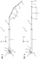
- FIGS. 1 to 4 show various representations of a probe guide 1 for guiding a probe.
- FIG. 1 shows a perspective view of the probe guide 1
- FIG. 2 shows a side view of the probe guide 1
- FIG. 3 shows a bottom view of the probe guide 1
- FIG. 4 shows a rear view of the probe guide. 1
- the probe guide 1 has a probe lance 3 and a movement unit 5 for moving the probe lance 3.
- the probe lance 3 comprises a process section 7, a central section 9, a probe holder 11 and a contact unit 13.
- the movement unit 5 comprises a holder 15, a drive unit 17 and an interface 19, which can be connected to a robot arm 38 of an industrial robot 30 (see the US Pat FIGS. 5 to 7 ).
- the operation section 7 of the probe lance 3 is formed as a straight tube which is guided in the holder 15 of the track 5 and is linearly movable by the drive unit 17 of the track 5 relative to the holder 15 along a longitudinal axis of the procedural section 7.
- the drive unit 17 has a drive 21 arranged on the holder 15, which drives the travel section 7 via a mechanism for converting a rotational movement of the drive 21 into a translatory movement.
- the drive 21 is designed, for example, as an electric motor.
- the Mechanism for converting a rotational movement of the drive 21 in a translational movement of the procedural section 7 is formed for example as a transmission, wherein the transmission, for example, a gear and a rack, which is arranged on the procedural section 7 or part of the procedural section 7 has.
- the central portion 9 of the probe lance 3 adjoins the working portion 7 and has a plurality (three in the illustrated embodiment) tubular straight subsections 23 to 25, which are angled away from each other.
- the central portion 9 is releasably connected to the procedural section 7, for example via a screw connection.
- the probe holder 11 of the probe lance 3 adjoins the central portion 9 and is releasably connected to this, for example via a screw, so that the probe holder 11 is replaceable.
- the probe holder 11 is formed as a straight tube.
- the contact unit 13 adjoins the probe holder 11 and forms a lance end of the probe lance 3.
- the contact unit 13 is releasably connected to a probe holder end of the probe holder 11 via a screw connection, so that the contact unit 13 is replaceable.
- the contact unit 13 has electrical contacts for contacting a sensor of a probe 2. By the probe lance 3 electrical signal lines are guided to the electrical contacts of the contact unit 13.
- the interface 19 of the moving part 5 projects laterally from the holder 15 and is designed to be fastened to a flange 40 of the robot arm 38 (see also FIGS FIGS. 5 to 7 ).
- a flange 40 of the robot arm 38 For this purpose, an end facing away from the bracket 15 of the interface 19 a plurality of holes 27, each with an internal thread for attachment to the flange 40 by means of screw.
- the drive unit 17 and the electrical contacts of the contact unit 13 electrically connected to the industrial robot 30, so that the drive unit 17 can be controlled by the industrial robot 30 and the industrial robot 30, the electric signals received by the contact unit 13 are supplied.
- the interface 19 thus serves the mechanical and electrical connection of the probe guide 1 with the industrial robot 30.
- the probe lance 3 has a length of several meters.
- the operation section 7 is about 3 m long
- a first subsection 23 of the middle section 9 is for example about 2 m long
- a second subsection 24 of the middle section 9 is for example about 1.5 m long
- a third subsection 25 of the central section 9 is for example approximately 0.5 m long
- the probe holder 11 is for example about 1 m long.
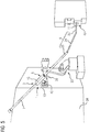
- FIGS. 5 to 7 show an industrial robot 30 with a like in the FIGS. 1 to 4 executed probe guide 1 in different phases of feeding a probe 2 to a metallurgical vessel 32, in which there is liquid steel.
- the metallurgical vessel 32 is, for example, a conventional steel converter or an electric arc furnace.
- a protective wall 34 which has a relatively narrow wall opening 36 with dimensions of, for example, approximately 50 cm ⁇ 100 cm for the passage of probes 2 to the metallurgical vessel 32.
- the industrial robot 30 is formed as a conventional 6-axis articulated-arm robot with a movable robot arm 38.
- the interface 19 of the track unit 5 of the probe guide 1 is connected to the robot arm 38, wherein the interface 19 is fastened by screw connections to a flange 40 of the robot arm 38.
- the drive unit 17 and the electrical contacts of the contact unit 13 of the probe guide 1 via the interface 19 are electrically connected to the industrial robot 30th connected, so that the drive unit 17 can be controlled by the industrial robot 30 and the industrial robot 30, the electrical signals received by the contact unit 13 are supplied.
- the probe lance 3 is first moved to a probe magazine 42, which is designed for the storage of probes 2. Thereafter, the probe holder 11 is connected either fully automatically or manually with a probe 2.
- Each probe 2 has an opening into which the contact unit 13 and the probe holder 11 can be retracted while being connected to the probe 2.
- the probes 2 are each designed to remove a sample of liquid steel from the metallurgical vessel 32 and / or to carry out a measurement, for example the measurement of a temperature of the liquid steel.
- Probes 2 for carrying out a measurement have a corresponding sensor which is electrically connected to the electrical contacts of the contact unit 13 when retracting the contact unit 13 into the probe 2.
- the industrial robot 30 introduces the probe holder 11 in the probe magazine 42 and connects the probe holder 11 with a probe 2 by the contact unit 13 and the probe holder 11 enters the probe 2.
- the industrial robot 30 recognizes, for example, with an image recognition system, occupied and empty probe positions of the probe magazine 42 automatically and selects an occupied probe site.
- FIG. 5 shows the industrial robot 30 when inserting the probe holder 11 into the probe magazine 42.
- the probe lance 3 with the probe 2 from the industrial robot 30 to the metallurgical vessel 32 back moved and the probe 2 and the front part of the probe lance 3 are guided by the industrial robot 30 through the wall opening 36 in the protective wall 34 to the metallurgical vessel 32.
- FIG. 6 shows the industrial robot 30 when passing the probe 2 through the wall opening 36 in the protective wall 34th
- the procedural section 7 of the probe lance 3 is moved by means of the moving unit 5 of the probe guide 1 to the metallurgical vessel 32 until the probe 2 reaches a predetermined immersion depth, for example an immersion depth of about 60 cm, in the liquid steel, wherein the moving unit 5 of the industrial robot 30 is controlled.
- FIG. 7 shows the industrial robot 30 during insertion of the probe 2 in the metallurgical vessel 32nd
- a sample of the liquid steel is removed by means of the probe 2 and / or a measurement is carried out.
- the probe 2 is held in the immersion depth in the liquid steel for a predetermined period of time, for example, until the sample is taken.
- the sampling takes place, for example, by burning a cardboard casing around a sampling body of the probe 2 in the liquid steel.
- the probe 2 is led out of the metallurgical vessel 32 at the probe lance 3 by the procedural section 7 of the probe lance 3 is moved away by means of the track unit 5 of the probe guide 1 of the metallurgical vessel 32, wherein the moving unit 5 of the industrial robot 30 is controlled.
- the probe 2 and the front part of the probe lance 3 are pulled by the industrial robot 30 through the wall opening 36 in the protective wall 34 and the probe 2 is placed on a free storage space of a (not shown) storage magazine, the industrial robot 30, the free storage space, for example automatically detects or the probe 2 is manually separated from the probe lance 3.
Abstract
Die Erfindung betrifft eine Sondenführung (1) zum Führen einer Sonde (2), insbesondere zum automatisierten Einführen einer Sonde (2) in ein metallurgisches Gefäß (32) und Ausführen der Sonde (2) aus dem metallurgischen Gefäß (32). Die Sondenführung (1) umfasst eine Sondenlanze (3) mit einem Sondenhalter (11) für die Sonde (2) und eine Verfahreinheit (5) zum Verfahren der Sondenlanze (3). Die Verfahreinheit (5) weist eine mit einem Roboterarm (38) eines Industrieroboters (30) verbindbare Schnittstelle (19) auf.The invention relates to a probe guide (1) for guiding a probe (2), in particular for the automated introduction of a probe (2) into a metallurgical vessel (32) and carrying out the probe (2) from the metallurgical vessel (32). The probe guide (1) comprises a probe lance (3) with a probe holder (11) for the probe (2) and a displacement unit (5) for moving the probe lance (3). The movement unit (5) has an interface (19) which can be connected to a robot arm (38) of an industrial robot (30).
Description
Die Erfindung betrifft eine Sondenführung zum Führen einer Sonde sowie einen Industrieroboter und ein Verfahren zum automatisierten Einführen einer Sonde in ein metallurgisches Gefäß und Ausführen der Sonde aus dem metallurgischen Gefäß.The invention relates to a probe guide for guiding a probe and to an industrial robot and to a method for automatically introducing a probe into a metallurgical vessel and for carrying out the probe from the metallurgical vessel.
Bei der Herstellung von Stahl werden häufig aus einem metallurgischen Gefäß, das Flüssigstahl enthält, metallurgische Proben des Flüssigstahls entnommen. In Stahlwerken, die aus Platz- oder Kostengründen nicht über eine Probenentnahmevorrichtung verfügen, wird zur Probenentnahme eine Sonde in das metallurgische Gefäß eingeführt. Sonden werden ferner zur Messung einer Temperatur des Flüssigstahls in ein metallurgisches Gefäß eingeführt. Die Sonden werden beispielsweise an einer Sondenlanze manuell oder halbautomatisch in das metallurgische Gefäß eingeführt. Ein derartiges Bedienen einer Sondenlanze unter Mithilfe von menschlichen Bedienern stellt für die Bediener jedoch ein hohes Sicherheitsrisiko dar. So kann es beispielsweise zu Verpuffungen kommen, wenn dem Stahlbad Schrott beigegeben wurde, der Wassereinschlüsse enthält.In the production of steel, metallurgical samples of the liquid steel are often taken from a metallurgical vessel containing liquid steel. In steelworks that do not have a sampling device for space or cost reasons, a probe is inserted into the metallurgical vessel for sampling. Probes are also introduced to measure a temperature of the liquid steel in a metallurgical vessel. For example, the probes are manually or semi-automatically inserted into the metallurgical vessel at a probe lance. Such operation of a probe lance with the assistance of human operators, however, poses a high safety risk for the operator. For example, deflagrations may occur if the steel bath contains scrap containing water inclusions.
Der Erfindung liegt die Aufgabe zugrunde, eine verbesserte Vorrichtung zum Führen einer Sonde, insbesondere zum automatisierten Einführen einer Sonde in ein metallurgisches Gefäß und Ausführen der Sonde aus dem metallurgischen Gefäß, sowie ein verbessertes Verfahren zum Einführen einer Sonde in ein metallurgisches Gefäß und Ausführen der Sonde aus dem metallurgischen Gefäß anzugeben.The invention is based on the object, an improved device for guiding a probe, in particular for automated introduction of a probe into a metallurgical vessel and carrying out the probe from the metallurgical vessel, and an improved method for introducing a probe into a metallurgical vessel and performing the probe from the metallurgical vessel.
Die Aufgabe wird erfindungsgemäß hinsichtlich der Vorrichtung durch eine Sondenführung mit den Merkmalen des Anspruchs 1 und durch einen Industrieroboter mit den Merkmalen des Anspruchs 12 und hinsichtlich des Verfahrens durch die Merkmale des Anspruchs 14 gelöst.The object is achieved with respect to the device by a probe guide with the features of
Vorteilhafte Ausgestaltungen der Erfindung sind Gegenstand der Unteransprüche.Advantageous embodiments of the invention are the subject of the dependent claims.
Eine erfindungsgemäße Sondenführung zum Führen einer Sonde umfasst eine Sondenlanze mit einem Sondenhalter für die Sonde und eine Verfahreinheit zum Verfahren der Sondenlanze, wobei die Verfahreinheit eine mit einem Roboterarm eines Industrieroboters verbindbare Schnittstelle aufweist.A probe guide according to the invention for guiding a probe comprises a probe lance with a probe holder for the probe and a displacement unit for moving the probe lance, wherein the displacement unit has an interface which can be connected to a robot arm of an industrial robot.
Die erfindungsgemäße Sondenführung ist besonders zum automatisierten Einführen einer Sonde in ein metallurgisches Gefäß und Ausführen der Sonde aus dem metallurgischen Gefäß mittels eines Industrieroboters geeignet. Dazu weist die Sondenführung eine mit einem Roboterarm eines Industrieroboters verbindbare Schnittstelle auf. Der Sondenhalter der Sondenlanze ermöglicht die Aufnahme einer Sonde durch die Sondenführung. Die Verfahreinheit ermöglicht, eine Sonde an der Sondenlanze in das metallurgische Gefäß einzuführen und aus dem Gefäß herauszuführen. Dies ermöglicht das Ein- und Ausführen der Sonde mittels eines herkömmlichen 6-achsigen Gelenkarmroboters, dessen Aktionsradius auf maximal etwa drei Meter eingeschränkt ist, da er ausschließlich über Drehachsen, jedoch keinen Linearantrieb verfügt und seine mögliche Kinematik daher in einer Kombination von reinen Drehbewegungen besteht. Dieser Aktionsradius ist zum Einführen der Sonde durch die Bewegung der Sondenlanze allein über die Bewegung des Roboterarms in der Regel nicht ausreichend. Daher sieht die Erfindung eine Verfahreinheit vor, mit der die Sondenlanze zusätzlich verfahren werden kann. Gegenüber einer Linearbewegung des gesamten Roboters ist das Verfahren der Sondenlanze mittels der Verfahreinheit deutlich kostengünstiger, da ein Industrieroboter typisch bis zu mehrere Tonnen wiegen kann und daher nur mit entsprechend hohem Aufwand linear bewegbar ist. Überdies hätte das Verfahren des gesamten Roboters beispielsweise auf Bodenschienen den Nachteil, dass die dazu erforderlichen Bodenschienen ein Hindernis in dem Bereich des metallurgischen Gefäßes darstellen würden. Zudem wird eine ortsfeste Anordnung des Roboters gegenüber einer verfahrbaren Anordnung bevorzugt, da auch Raum für anderweitige Tätigkeiten in dem Bereich des metallurgischen Gefäßes benötigt wird. Ein weiterer Vorteil des automatisierten Ein- und Ausführens einer Sonde mit einem Roboter besteht darin, dass dem Roboter in einfacher Weise die Höhe des Flüssigkeitsspiegels in dem metallurgischen Gefäß von einer Anlagenautomation übermittelt werden kann und daher von dem Roboter im Unterschied zu einem menschlichen Bediener eine geforderte Eintauchtiefe der Sonde von beispielsweise etwa 60 cm unter dem Flüssigkeitsspiegel zuverlässig reproduziert werden kann.The probe guide according to the invention is particularly suitable for automatically introducing a probe into a metallurgical vessel and for carrying out the probe from the metallurgical vessel by means of an industrial robot. For this purpose, the probe guide has an interface which can be connected to a robot arm of an industrial robot. The probe holder of the probe lance allows the insertion of a probe through the probe guide. The track allows to insert a probe on the probe lance into the metallurgical vessel and out of the vessel. This allows the insertion and removal of the probe by means of a conventional 6-axis articulated arm robot whose radius of action is limited to a maximum of about three meters, as it has only rotary axes, but no linear drive and its possible kinematics therefore consists in a combination of pure rotational movements. This action radius is for inserting the probe through the movement the probe lance alone is generally insufficient over the movement of the robotic arm. Therefore, the invention provides a track, with which the probe lance can be moved additionally. Compared to a linear movement of the entire robot, the method of the probe lance by means of the track is significantly cheaper, since an industrial robot can typically weigh up to several tons and therefore is linearly movable only with a correspondingly high cost. Moreover, the process of the entire robot, for example on floor rails, would have the disadvantage that the floor rails required would be an obstacle in the area of the metallurgical vessel. In addition, a fixed arrangement of the robot relative to a movable arrangement is preferred, since space is also needed for other activities in the area of the metallurgical vessel. A further advantage of the automated insertion and removal of a probe with a robot is that the level of the liquid level in the metallurgical vessel can easily be transmitted to the robot by a plant automation and therefore demanded by the robot as opposed to a human operator Immersion depth of the probe, for example, about 60 cm below the liquid level can be reliably reproduced.
Eine Ausgestaltung der Erfindung sieht vor, dass die Sondenlanze einen geraden Verfahrabschnitt aufweist, und dass die Verfahreinheit eine Antriebseinheit zum Verschieben des Verfahrabschnitts relativ zu der Verfahreinheit entlang einer Längsachse des Verfahrabschnitts aufweist. Beispielsweise weist die Verfahreinheit eine Halterung auf, in der der Verfahrabschnitt geführt ist. Die Antriebseinheit weist beispielsweise einen Antrieb zum Verschieben des Verfahrabschnitts auf. Ferner kann die Antriebseinheit einen Mechanismus zur Umwandlung einer rotatorischen Bewegung des Antriebs in eine translatorische Bewegung des Verfahrabschnitts aufweisen. Dieser Mechanismus ist beispielsweise ein Getriebe wie ein Zahnrad und eine Zahnstange. Diese Ausgestaltungen der Erfindung ermöglichen eine besonders einfache und kostengünstige Realisierung der Verfahreinheit durch eine Antriebseinheit.An embodiment of the invention provides that the probe lance has a straight drive section, and that the moving unit has a drive unit for displacing the drive section relative to the displacement unit along a longitudinal axis of the travel section. For example, the moving part has a holder in which the working section is guided. The drive unit has, for example, a drive for displacing the travel section. Furthermore, the drive unit can have a mechanism for converting a rotational movement of the drive into a translational movement of the travel section. This mechanism is for example a gear like a gear and a gear Rack. These embodiments of the invention allow a particularly simple and cost-effective implementation of the track unit by a drive unit.
Eine alternative Ausgestaltung der Erfindung sieht vor, dass die Verfahreinheit einen Teleskoparm aufweist, an dem die Sondenlanze angeordnet ist. Gegenüber einer Verfahreinheit mit einer Antriebseinheit zum Verfahren des Verfahrabschnitts der Sondenlanze ist eine Verfahreinheit mit einem Teleskoparm zwar kostenaufwändiger, dafür jedoch platzsparender, da die Sondenlanze keinen Verfahrabschnitt aufweisen muss, der in der Regel mehrere Meter lang ist. Eine Verfahreinheit mit einem Teleskoparm ist daher vorteilhaft, wenn die Länge der Sondenlanze aus Platzgründen beschränkt werden soll. Üblicherweise steht jedoch in dem Bereich des metallurgischen Gefäßes ausreichend Platz zur Verfügung, so dass eine Verfahreinheit mit einer Antriebseinheit für einen Verfahrabschnitt der Sondenlanze gegenüber einer Verfahreinheit mit einem Teleskoparm bevorzugt ist.An alternative embodiment of the invention provides that the moving part has a telescopic arm on which the probe lance is arranged. Compared with a moving part with a drive unit for moving the working section of the probe lance, a moving part with a telescopic arm is more costly, but more space-saving, because the probe lance does not have to have a working section, which is usually several meters long. A displacement unit with a telescopic arm is therefore advantageous if the length of the probe lance is to be limited for reasons of space. Usually, however, sufficient space is available in the region of the metallurgical vessel, so that a moving unit with a drive unit for a travel section of the probe lance is preferred over a moving part with a telescopic arm.
Eine weitere Ausgestaltung der Erfindung sieht vor, dass die Sonde vollautomatisch oder halbautomatisch auf den Sondenhalter aufgesteckt wird. Die Sonde weist beispielsweise ein Kartonrohr auf, an dem ein Probenentnahmekörper zur Entnahme einer Probe aus dem metallurgischen Gefäß und/oder eine Sensorik zur Durchführung einer Messung in dem metallurgischen Gefäß angeordnet ist.A further embodiment of the invention provides that the probe is plugged fully automatically or semi-automatically on the probe holder. The probe has, for example, a cardboard tube on which a sampling body for removing a sample from the metallurgical vessel and / or a sensor system for carrying out a measurement in the metallurgical vessel is arranged.
Eine weitere Ausgestaltung der Erfindung sieht vor, dass die Sondenlanze eine an einem Sondenhalterende des Sondenhalters angeordnete Kontakteinheit mit elektrischen Kontakten zum Kontaktieren einer Sensorik der Sonde aufweist, und dass durch die Sondenlanze elektrische Signalleitungen zu den elektrischen Kontakten der Kontakteinheit geführt sind. Diese Ausgestaltung der Erfindung ermöglicht, eine Sensorik einer Sonde direkt über die Kontakteinheit und die elektrische Signalleitungen der Sondenlanze sowie über die Schnittstelle der Verfahreinheit mit dem Industrieroboter zu verbinden, so dass von der Sonde erfasste Messsignale direkt von dem Industrieroboter gespeichert oder an ein übergeordnetes Anlagensystem weitergeleitet werden können.A further embodiment of the invention provides that the probe lance has a arranged at a probe holder end of the probe holder contact unit with electrical contacts for contacting a sensor of the probe, and that are guided by the probe lance electrical signal lines to the electrical contacts of the contact unit. This embodiment of the invention makes it possible to connect a sensor system of a probe directly to the industrial robot via the contact unit and the electrical signal lines of the probe lance as well as via the interface of the moving part that detected by the probe measurement signals can be stored directly from the industrial robot or forwarded to a higher-level system.
Eine weitere Ausgestaltung der Erfindung sieht vor, dass die Kontakteinheit lösbar mit dem Sondenhalterende verbunden ist. Dies ermöglicht, die Kontakteinheit, beispielsweise bei einem Defekt, auszuwechseln.A further embodiment of the invention provides that the contact unit is detachably connected to the probe holder end. This makes it possible to replace the contact unit, for example in the event of a defect.
Eine weitere Ausgestaltung der Erfindung sieht vor, dass der Sondenhalter lösbar mit einem Mittelabschnitt der Sondenlanze verbunden ist. Dabei kann der Mittelabschnitt lösbar mit dem Verfahrabschnitt der Sondenlanze verbunden sein. Dies ermöglicht, den Sondenhalter und/oder den Mittelabschnitt, beispielsweise bei einem Defekt, auszuwechseln.A further embodiment of the invention provides that the probe holder is detachably connected to a central portion of the probe lance. In this case, the middle section can be releasably connected to the operation section of the probe lance. This makes it possible to replace the probe holder and / or the central portion, for example in the event of a defect.
Eine weitere Ausgestaltung der Erfindung sieht vor, dass die Schnittstelle zur Befestigung an einem Flansch des Roboterarms ausgebildet ist. Dadurch kann die Sondenführung mittels der Schnittstelle der Verfahreinheit vorteilhaft durch eine Standardbefestigung mit dem Roboterarm verbunden werden.A further embodiment of the invention provides that the interface for attachment to a flange of the robot arm is formed. As a result, the probe guide can advantageously be connected to the robot arm by means of the interface of the track unit by means of a standard attachment.
Ein erfindungsgemäßer Industrieroboter zum automatisierten Einführen einer Sonde in ein metallurgisches Gefäß und Ausführen der Sonde aus dem metallurgischen Gefäß umfasst einen bewegbaren Roboterarm und eine erfindungsgemäße Sondenführung, wobei die Schnittstelle der Verfahreinheit der Sondenführung mit dem Roboterarm verbunden ist. Dabei ist die Verfahreinheit der Sondenführung vorzugsweise durch den Industrieroboter ansteuerbar. Ein derartiger Industrieroboter ermöglicht das automatisierte Einführen einer Sonde in ein metallurgisches Gefäß und Ausführen der Sonde aus dem metallurgischen Gefäß mit den oben bereits genannten Vorteilen.An industrial robot according to the invention for automatically introducing a probe into a metallurgical vessel and executing the probe from the metallurgical vessel comprises a movable robot arm and a probe guide according to the invention, wherein the interface of the track of the probe guide is connected to the robot arm. The trajectory of the probe guide is preferably controlled by the industrial robot. Such an industrial robot allows the automated introduction of a probe into a metallurgical vessel and the probe from the metallurgical vessel with the advantages already mentioned above.
Bei dem erfindungsgemäßen Verfahren wird eine Sonde mit einem erfindungsgemäßen Industrieroboter automatisiert in ein metallurgisches Gefäß eingeführt und aus dem metallurgischen Gefäß herausgeführt, wobei die Sondenlanze von dem Industrieroboter zu der Sonde bewegt wird, der Sondenhalter mit der Sonde verbunden wird, die Sondenlanze mit der Sonde von dem Industrieroboter zu dem metallurgischen Gefäß bewegt wird, die Sonde an der Sondenlanze von dem Industrieroboter in das metallurgische Gefäß eingeführt wird und die Sonde an der Sondenlanze von dem Industrieroboter aus dem metallurgischen Gefäß herausgeführt wird.In the method according to the invention, a probe with an industrial robot according to the invention is automated in a introduced metallurgical vessel and led out of the metallurgical vessel, wherein the probe lance is moved from the industrial robot to the probe, the probe holder is connected to the probe, the probe lance is moved with the probe from the industrial robot to the metallurgical vessel, the probe at the probe lance is introduced from the industrial robot in the metallurgical vessel and the probe is guided at the probe lance of the industrial robot from the metallurgical vessel.
Die oben beschriebenen Eigenschaften, Merkmale und Vorteile dieser Erfindung sowie die Art und Weise, wie diese erreicht werden, werden klarer und deutlicher verständlich im Zusammenhang mit der folgenden Beschreibung von Ausführungsbeispielen, die im Zusammenhang mit den Zeichnungen näher erläutert werden. Dabei zeigen:
-
FIG 1 eine perspektivische Darstellung einer Sondenführung, -
FIG 2 eine Seitenansicht der inFigur 1 -
FIG 3 eine Unteransicht der inFigur 1 -
FIG 4 eine Rückansicht der inFigur 1 -
FIG 5 eine perspektivische Darstellung eines Industrieroboters beim Aufnehmen einer Sonde aus einem Sondenmagazin, -
FIG 6 eine perspektivische Darstellung des inFigur 5 -
FIG 7 eine perspektivische Draufsicht des inFigur 5
-
FIG. 1 a perspective view of a probe guide, -
FIG. 2 a side view of inFIG. 1 shown probe guide, -
FIG. 3 a bottom view of inFIG. 1 shown probe guide, -
FIG. 4 a rear view of the inFIG. 1 shown probe guide, -
FIG. 5 a perspective view of an industrial robot when picking up a probe from a probe magazine, -
FIG. 6 a perspective view of the inFIG. 5 shown industrial robot when feeding the probe to a metallurgical vessel, -
FIG. 7 a perspective top view of the inFIG. 5 shown industrial robot during insertion of the probe into the metallurgical vessel.
Einander entsprechende Teile sind in den Figuren mit denselben Bezugszeichen versehen.Corresponding parts are provided in the figures with the same reference numerals.
Die
Die Sondenführung 1 weist eine Sondenlanze 3 und eine Verfahreinheit 5 zum Verfahren der Sondenlanze 3 auf.The
Die Sondenlanze 3 umfasst einen Verfahrabschnitt 7, einen Mittelabschnitt 9, einen Sondenhalter 11 und eine Kontakteinheit 13.The
Die Verfahreinheit 5 umfasst eine Halterung 15, eine Antriebseinheit 17 und eine Schnittstelle 19, die mit einem Roboterarm 38 eines Industrieroboters 30 verbindbar ist (siehe dazu die
Der Verfahrabschnitt 7 der Sondenlanze 3 ist als ein gerades Rohr ausgebildet, das in der Halterung 15 der Verfahreinheit 5 geführt ist und durch die Antriebseinheit 17 der Verfahreinheit 5 relativ zu der Halterung 15 entlang einer Längsachse des Verfahrabschnitts 7 linear bewegbar ist.The
Beispielsweise weist die Antriebseinheit 17 einen an der Halterung 15 angeordneten Antrieb 21 auf, der den Verfahrabschnitt 7 über einen Mechanismus zur Umwandlung einer rotatorischen Bewegung des Antriebs 21 in eine translatorische Bewegung antreibt. Der Antrieb 21 ist beispielsweise als ein Elektromotor ausgeführt. Der Mechanismus zur Umwandlung einer rotatorischen Bewegung des Antriebs 21 in eine translatorische Bewegung des Verfahrabschnitts 7 ist beispielsweise als ein Getriebe ausgebildet, wobei das Getriebe beispielsweise ein Zahnrad und eine Zahnstange, die an dem Verfahrabschnitt 7 angeordnet beziehungsweise Teil des Verfahrabschnitts 7 ist, aufweist.For example, the
Der Mittelabschnitt 9 der Sondenlanze 3 schließt sich an den Verfahrabschnitt 7 an und weist mehrere (im dargestellten Ausführungsbeispiel drei) rohrartige gerade Unterabschnitte 23 bis 25 auf, die voneinander abgewinkelt sind. Der Mittelabschnitt 9 ist mit dem Verfahrabschnitt 7 beispielsweise über eine Schraubverbindung lösbar verbunden.The
Der Sondenhalter 11 der Sondenlanze 3 schließt sich an den Mittelabschnitt 9 an und ist mit diesem beispielsweise über eine Schraubverbindung lösbar verbunden, so dass der Sondenhalter 11 auswechselbar ist. Der Sondenhalter 11 ist als ein gerades Rohr ausgebildet.The
Die Kontakteinheit 13 schließt sich an den Sondenhalter 11 an und bildet ein Lanzenende der Sondenlanze 3. Beispielsweise ist die Kontakteinheit 13 mit einem Sondenhalterende des Sondenhalters 11 über eine Schraubverbindung lösbar verbunden, so dass die Kontakteinheit 13 auswechselbar ist. Die Kontakteinheit 13 weist elektrische Kontakte zum Kontaktieren einer Sensorik einer Sonde 2 auf. Durch die Sondenlanze 3 sind elektrische Signalleitungen zu den elektrischen Kontakten der Kontakteinheit 13 geführt.The
Die Schnittstelle 19 der Verfahreinheit 5 steht seitlich von der Halterung 15 ab und ist zur Befestigung an einem Flansch 40 des Roboterarms 38 ausgebildet (siehe dazu die
Die Sondenlanze 3 hat eine Länge von mehreren Metern. Beispielsweise ist der Verfahrabschnitt 7 etwa 3 m lang, ein erster Unterabschnitt 23 des Mittelabschnitts 9 ist beispielsweise etwa 2 m lang, ein zweiter Unterabschnitt 24 des Mittelabschnitts 9 ist beispielsweise etwa 1,5 m lang, ein dritter Unterabschnitt 25 des Mittelabschnitts 9 ist beispielsweise etwa 0,5 m lang und der Sondenhalter 11 ist beispielsweise etwa 1 m lang.The
Die
Der Industrieroboter 30 ist als ein herkömmlicher 6-achsiger Gelenkarmroboter mit einem bewegbaren Roboterarm 38 ausgebildet. Die Schnittstelle 19 der Verfahreinheit 5 der Sondenführung 1 ist mit dem Roboterarm 38 verbunden, wobei die Schnittstelle 19 durch Schraubverbindungen an einem Flansch 40 des Roboterarms 38 befestigt ist. Ferner sind die Antriebseinheit 17 und die elektrischen Kontakte der Kontakteinheit 13 der Sondenführung 1 über die Schnittstelle 19 elektrisch mit dem Industrieroboter 30 verbunden, so dass die Antriebseinheit 17 von dem Industrieroboter 30 ansteuerbar ist und dem Industrieroboter 30 die von der Kontakteinheit 13 empfangenen elektrischen Signale zugeführt werden.The
Mit dem Industrieroboter 30 wird die Sondenlanze 3 zunächst zu einem Sondenmagazin 42 bewegt, das zur Lagerung von Sonden 2 ausgebildet ist. Danach wird der Sondenhalter 11 entweder vollautomatisch oder manuell mit einer Sonde 2 verbunden.With the
Jede Sonde 2 weist eine Öffnung auf, in die die Kontakteinheit 13 und der Sondenhalter 11 eingefahren und dabei mit der Sonde 2 verbunden werden können. Die Sonden 2 sind beispielsweise jeweils zur Entnahme einer Probe von Flüssigstahl aus dem metallurgischen Gefäß 32 und/oder zur Durchführung einer Messung, beispielsweise der Messung einer Temperatur des Flüssigstahls, ausgebildet. Sonden 2 zur Durchführung einer Messung weisen eine entsprechende Sensorik auf, die beim Einfahren der Kontakteinheit 13 in die Sonde 2 elektrisch mit den elektrischen Kontakten der Kontakteinheit 13 verbunden wird.Each
Bei einer vollautomatischen Verbindung des Sondenhalters 11 mit einer Sonde 2 führt der Industrieroboter 30 den Sondenhalter 11 in das Sondenmagazin 42 ein und verbindet den Sondenhalter 11 mit einer Sonde 2, indem er die Kontakteinheit 13 und den Sondenhalter 11 in die Sonde 2 einfährt. Dabei erkennt der Industrieroboter 30, beispielsweise mit einem Bilderkennungssystem, belegte und leere Sondenplätze des Sondenmagazins 42 selbsttätig und wählt einen belegten Sondenplatz aus.In a fully automatic connection of the
Anschließend wird die Sondenlanze 3 mit der Sonde 2 von dem Industrieroboter 30 zu dem metallurgischen Gefäß 32 hin bewegt und die Sonde 2 und der vordere Teil der Sondenlanze 3 werden von dem Industrieroboter 30 durch die Maueröffnung 36 in der Schutzmauer 34 zu dem metallurgischen Gefäß 32 geführt.Subsequently, the
Danach wird der Verfahrabschnitt 7 der Sondenlanze 3 mittels der Verfahreinheit 5 der Sondenführung 1 zu dem metallurgischen Gefäß 32 hin verfahren bis die Sonde 2 eine vorgegebene Eintauchtiefe, beispielsweise eine Eintauchtiefe von etwa 60 cm, in dem Flüssigstahl erreicht, wobei die Verfahreinheit 5 von dem Industrieroboter 30 gesteuert wird.Thereafter, the
Anschließend wird mittels der Sonde 2 eine Probe des Flüssigstahls entnommen und/oder eine Messung durchgeführt. Zum Entnehmen einer Probe wird die Sonde 2 beispielsweise eine vorgegebene Zeitdauer in der Eintauchtiefe in dem Flüssigstahl gehalten bis die Probe entnommen ist. Die Probenentnahme geschieht beispielsweise durch das Durchbrennen einer Kartonummantelung um einen Probenentnahmekörper der Sonde 2 in dem Flüssigstahl. Bei der Durchführung einer Messung werden die von der Sonde 2 aufgenommenen Messdaten über die Kontakteinheit 13, die durch die Sondenlanze 3 geführten elektrischen Signalleitungen und die Schnittstelle 19 der Sondenführung 1 dem Industrieroboter 30 zugeführt und von diesem gespeichert und/oder an ein übergeordnetes Anlagensystem weitergeleitet.Subsequently, a sample of the liquid steel is removed by means of the
Danach wird die Sonde 2 an der Sondenlanze 3 aus dem metallurgischen Gefäß 32 herausgeführt, indem der Verfahrabschnitt 7 der Sondenlanze 3 mittels der Verfahreinheit 5 der Sondenführung 1 von dem metallurgischen Gefäß 32 weg verfahren wird, wobei die Verfahreinheit 5 von dem Industrieroboter 30 gesteuert wird. Abschließend werden die Sonde 2 und der vordere Teil der Sondenlanze 3 von dem Industrieroboter 30 durch die Maueröffnung 36 in der Schutzmauer 34 hindurchgezogen und die Sonde 2 wird auf einen freien Ablageplatz eines (nicht dargestellten) Ablagemagazins abgelegt, wobei der Industrieroboter 30 den freien Ablageplatz beispielsweise selbsttätig erkennt oder die Sonde 2 wird manuell von der Sondenlanze 3 getrennt.Thereafter, the
Obwohl die Erfindung im Detail durch bevorzugte Ausführungsbeispiele näher illustriert und beschrieben wurde, so ist die Erfindung nicht durch die offenbarten Beispiele eingeschränkt und andere Variationen können vom Fachmann hieraus abgeleitet werden, ohne den Schutzumfang der Erfindung zu verlassen.While the invention has been further illustrated and described in detail by way of preferred embodiments, the invention is not limited by the disclosed examples, and other variations can be derived therefrom by those skilled in the art without departing from the scope of the invention.
- 11
- Sondenführungprobe guide
- 22
- Sondeprobe
- 33
- Sondenlanzelance probe
- 55
- Verfahreinheittraversing
- 77
- VerfahrabschnittVerfahrabschnitt
- 99
- Mittelabschnittmidsection
- 1111
- Sondenhalterprobe holder
- 1313
- KontakteinheitContact unit
- 1515
- Halterungholder
- 1717
- Antriebseinheitdrive unit
- 1919
- Schnittstelleinterface
- 2121
- Antriebdrive
- 23 bis 2523 to 25
- Unterabschnittsubsection
- 2727
- Bohrungdrilling
- 3030
- Industrieroboterindustrial robots
- 3232
- metallurgisches Gefäßmetallurgical vessel
- 3434
- Schutzmauerprotective wall
- 3636
- Maueröffnungwall opening
- 3838
- Roboterarmrobot arm
- 4040
- Flanschflange
- 4242
- Sondenmagazinprobe Magazine
Claims (14)
dadurch gekennzeichnet, dass die Sondenlanze (3) einen geraden Verfahrabschnitt (7) aufweist, und dass die Verfahreinheit (5) eine Antriebseinheit (17) zum Verschieben des Verfahrabschnitts (7) relativ zu der Verfahreinheit (5) entlang einer Längsachse des Verfahrabschnitts (7) aufweist.Probe guide (1) according to claim 1,
characterized in that the probe lance (3) has a straight drive section (7), and in that the moving unit (5) has a drive unit (17) for displacing the drive section (7) relative to the moving unit (5) along a longitudinal axis of the travel section (7 ) having.
dadurch gekennzeichnet, dass die Verfahreinheit (5) eine Halterung (15) aufweist, in der der Verfahrabschnitt (7) geführt ist.Probe guide (1) according to claim 2,
characterized in that the moving unit (5) has a holder (15), in which the procedural section (7) is guided.
dadurch gekennzeichnet, dass die Antriebseinheit (17) einen Antrieb (21) zum Verschieben des Verfahrabschnitts (7) aufweist.Probe guide (1) according to claim 2 or 3,
characterized in that the drive unit (17) has a drive (21) for displacing the operation section (7).
dadurch gekennzeichnet, dass die Antriebseinheit (17) einen Mechanismus zur Umwandlung einer rotatorischen Bewegung des Antriebs (21) in eine translatorische Bewegung des Verfahrabschnitts (7) aufweist.Probe guide (1) according to claim 4,
characterized in that the drive unit (17) has a mechanism for converting a rotational movement of the drive (21) in a translational movement of the procedural section (7).
dadurch gekennzeichnet, dass die Verfahreinheit (5) einen Teleskoparm aufweist, an dem die Sondenlanze (3) angeordnet ist.Probe guide (1) according to claim 1,
characterized in that the positioning unit (5) has a telescopic arm on which the probe lance (3) is arranged.
dadurch gekennzeichnet, dass die Sondenlanze (3) eine an einem Sondenhalterende des Sondenhalters (11) angeordnete Kontakteinheit (13) mit elektrischen Kontakten zum Kontaktieren einer Sensorik der Sonde (2) aufweist, und dass durch die Sondenlanze (3) elektrische Signalleitungen zu den elektrischen Kontakten der Kontakteinheit (13) geführt sind.Probe guide (1) according to one of the preceding claims,
characterized in that the probe lance (3) has a at a probe holder end of the probe holder (11) arranged contact unit (13) with electrical contacts for contacting a sensor of the probe (2), and that by the probe lance (3) electrical signal lines to the electrical Contacts of the contact unit (13) are guided.
dadurch gekennzeichnet, dass die Kontakteinheit (13) lösbar mit dem Sondenhalterende verbunden ist.Probe guide (1) according to claim 7,
characterized in that the contact unit (13) is detachably connected to the probe holder end.
dadurch gekennzeichnet, dass der Sondenhalter (11) lösbar mit einem Mittelabschnitt (9) der Sondenlanze (3) verbunden ist.Probe guide (1) according to one of the preceding claims,
characterized in that the probe holder (11) is releasably connected to a central portion (9) of the probe lance (3).
dadurch gekennzeichnet, dass der Mittelabschnitt (9) lösbar mit dem Verfahrabschnitt (7) der Sondenlanze (3) verbunden ist.Probe guide (1) according to claim 9,
characterized in that the central portion (9) is detachably connected to the operation portion (7) of the probe lance (3).
dadurch gekennzeichnet, dass die Schnittstelle (19) zur Befestigung an einem Flansch (40) des Roboterarms (38) ausgebildet ist.Probe guide (1) according to one of the preceding claims,
characterized in that the interface (19) is designed for attachment to a flange (40) of the robot arm (38).
dadurch gekennzeichnet, dass die Verfahreinheit (5) der Sondenführung (1) durch den Industrieroboter (30) ansteuerbar ist.Industrial robot (30) according to claim 12,
characterized in that the traversing unit (5) of the probe guide (1) by the industrial robot (30) is controllable.
Priority Applications (3)
| Application Number | Priority Date | Filing Date | Title |
|---|---|---|---|
| EP17179451.4A EP3425316A1 (en) | 2017-07-04 | 2017-07-04 | Guiding a probe |
| EP18733909.8A EP3649418B1 (en) | 2017-07-04 | 2018-07-03 | Guiding a probe |
| PCT/EP2018/067958 WO2019007963A1 (en) | 2017-07-04 | 2018-07-03 | Guiding a probe |
Applications Claiming Priority (1)
| Application Number | Priority Date | Filing Date | Title |
|---|---|---|---|
| EP17179451.4A EP3425316A1 (en) | 2017-07-04 | 2017-07-04 | Guiding a probe |
Publications (1)
| Publication Number | Publication Date |
|---|---|
| EP3425316A1 true EP3425316A1 (en) | 2019-01-09 |
Family
ID=59383400
Family Applications (2)
| Application Number | Title | Priority Date | Filing Date |
|---|---|---|---|
| EP17179451.4A Withdrawn EP3425316A1 (en) | 2017-07-04 | 2017-07-04 | Guiding a probe |
| EP18733909.8A Active EP3649418B1 (en) | 2017-07-04 | 2018-07-03 | Guiding a probe |
Family Applications After (1)
| Application Number | Title | Priority Date | Filing Date |
|---|---|---|---|
| EP18733909.8A Active EP3649418B1 (en) | 2017-07-04 | 2018-07-03 | Guiding a probe |
Country Status (2)
| Country | Link |
|---|---|
| EP (2) | EP3425316A1 (en) |
| WO (1) | WO2019007963A1 (en) |
Citations (4)
| Publication number | Priority date | Publication date | Assignee | Title |
|---|---|---|---|---|
| DE4034809A1 (en) * | 1990-11-02 | 1992-05-07 | Beda Oxygentech Armatur | Arc furnace lance robot used to manipulate e.g. carbon@ powder - has swing arms on rotating tower with motors to move the lances at required height and angle into the furnace |
| JPH06294791A (en) * | 1993-04-07 | 1994-10-21 | Osaka Oxygen Ind Ltd | Automatic equipment for fitting and removing probe for lance |
| WO2007057061A1 (en) | 2005-06-20 | 2007-05-24 | Siemens Vai Metals Technologies Gmbh & Co | Continuous casting plant having at least one multifunction robot |
| EP2490000A1 (en) | 2011-02-16 | 2012-08-22 | Siemens VAI Metals Technologies GmbH | Automatic insertion of a contact bar in a foundry probe |
Family Cites Families (1)
| Publication number | Priority date | Publication date | Assignee | Title |
|---|---|---|---|---|
| EP2482019B1 (en) * | 2011-01-31 | 2014-10-01 | Siemens VAI Metals Technologies GmbH | Burning lance holder for holding a burning lance by means of a handling device |
-
2017
- 2017-07-04 EP EP17179451.4A patent/EP3425316A1/en not_active Withdrawn
-
2018
- 2018-07-03 EP EP18733909.8A patent/EP3649418B1/en active Active
- 2018-07-03 WO PCT/EP2018/067958 patent/WO2019007963A1/en unknown
Patent Citations (4)
| Publication number | Priority date | Publication date | Assignee | Title |
|---|---|---|---|---|
| DE4034809A1 (en) * | 1990-11-02 | 1992-05-07 | Beda Oxygentech Armatur | Arc furnace lance robot used to manipulate e.g. carbon@ powder - has swing arms on rotating tower with motors to move the lances at required height and angle into the furnace |
| JPH06294791A (en) * | 1993-04-07 | 1994-10-21 | Osaka Oxygen Ind Ltd | Automatic equipment for fitting and removing probe for lance |
| WO2007057061A1 (en) | 2005-06-20 | 2007-05-24 | Siemens Vai Metals Technologies Gmbh & Co | Continuous casting plant having at least one multifunction robot |
| EP2490000A1 (en) | 2011-02-16 | 2012-08-22 | Siemens VAI Metals Technologies GmbH | Automatic insertion of a contact bar in a foundry probe |
Also Published As
| Publication number | Publication date |
|---|---|
| WO2019007963A1 (en) | 2019-01-10 |
| EP3649418A1 (en) | 2020-05-13 |
| EP3649418B1 (en) | 2021-03-31 |
Similar Documents
| Publication | Publication Date | Title |
|---|---|---|
| AT510292B1 (en) | DETERMINATION OF THE POSITION OF A CONTACT TABLE TO A PROBE HOLDER OF A HORIZONTAL PROBE | |
| DE2856311A1 (en) | DEVICE FOR TEMPERATURE MEASUREMENT AND SAMPLING IN A STEEL BATH | |
| EP1614758A2 (en) | Measuring lance for measuring operations and/or sampling in molten metals | |
| EP2255905A1 (en) | Apparatus for conducting operations inside a metallurgical vessel | |
| WO2018109233A1 (en) | Automatic connection and disconnection of two fluid lines | |
| EP0009585B1 (en) | Apparatus for conveying probes for attachment onto measuring or sampling lances in a metallurgical vessel | |
| EP0444006B1 (en) | An arrangement for installing and removing a lance into and from a metallurgical vessel and a method therefor | |
| DE2753161C3 (en) | Method and device for changing measuring and / or sampling probes for molten steel | |
| DE2807152C2 (en) | Device for handling measuring and sampling probes by means of measuring lances in melts | |
| EP3425316A1 (en) | Guiding a probe | |
| EP0364825B1 (en) | Apparatus for taking discontinuous measurements on molten metal | |
| DE2605365A1 (en) | DEVICE FOR TAKING SAMPLES OR FOR MEASURING THE TEMPERATURE IN METALLURGICAL VESSELS, IN PARTICULAR WITH A CONVERTER | |
| DE3141116C2 (en) | Method and device for carrying out successive temperature measurements and / or sampling and / or thermal analyzes in iron and steel melts | |
| DE19654522C2 (en) | Device for removing samples from a measuring probe | |
| WO2009153075A1 (en) | Arc furnace | |
| EP0297083A2 (en) | Spruing station for ladles | |
| EP0486462A1 (en) | Method and arrangement for preventing crusts from agglomerating in metallurgical vessesl | |
| DE2552270B2 (en) | DEVICE FOR INDEPENDENT MEASURING AND / OR SAMPLING IN A METAL MELT | |
| DE1930480C (en) | Device for changing an oxygen lance | |
| DE2753077B2 (en) | Device for changing measuring and / or sampling probes | |
| DE202023106984U1 (en) | Installation, robot and head for atomizing a product in an interior of a container suitable for containing molten metal | |
| DE3708818A1 (en) | DEVICE FOR TAKING A SAMPLE FROM A MELTING MELT | |
| DE102021102376A1 (en) | Manipulator for use in a casting hall | |
| DE202013006152U1 (en) | Ruhrstahl-Heraeus plant | |
| DE2839921A1 (en) | Manipulator for measuring lance inserted into molten metals - has support guide mounted on swivel arms so it does not impede access of blowing lance, esp. in converters |
Legal Events
| Date | Code | Title | Description |
|---|---|---|---|
| PUAI | Public reference made under article 153(3) epc to a published international application that has entered the european phase |
Free format text: ORIGINAL CODE: 0009012 |
|
| AK | Designated contracting states |
Kind code of ref document: A1 Designated state(s): AL AT BE BG CH CY CZ DE DK EE ES FI FR GB GR HR HU IE IS IT LI LT LU LV MC MK MT NL NO PL PT RO RS SE SI SK SM TR |
|
| AX | Request for extension of the european patent |
Extension state: BA ME |
|
| STAA | Information on the status of an ep patent application or granted ep patent |
Free format text: STATUS: THE APPLICATION IS DEEMED TO BE WITHDRAWN |
|
| 18D | Application deemed to be withdrawn |
Effective date: 20190710 |