EP3425201B1 - Volumetric pump - Google Patents
Volumetric pump Download PDFInfo
- Publication number
- EP3425201B1 EP3425201B1 EP17305891.8A EP17305891A EP3425201B1 EP 3425201 B1 EP3425201 B1 EP 3425201B1 EP 17305891 A EP17305891 A EP 17305891A EP 3425201 B1 EP3425201 B1 EP 3425201B1
- Authority
- EP
- European Patent Office
- Prior art keywords
- valve
- chamber
- fluid
- spool
- volume
- Prior art date
- Legal status (The legal status is an assumption and is not a legal conclusion. Google has not performed a legal analysis and makes no representation as to the accuracy of the status listed.)
- Active
Links
Images


Classifications
-
- F—MECHANICAL ENGINEERING; LIGHTING; HEATING; WEAPONS; BLASTING
- F04—POSITIVE - DISPLACEMENT MACHINES FOR LIQUIDS; PUMPS FOR LIQUIDS OR ELASTIC FLUIDS
- F04B—POSITIVE-DISPLACEMENT MACHINES FOR LIQUIDS; PUMPS
- F04B7/00—Piston machines or pumps characterised by having positively-driven valving
- F04B7/0076—Piston machines or pumps characterised by having positively-driven valving the members being actuated by electro-magnetic means
-
- F—MECHANICAL ENGINEERING; LIGHTING; HEATING; WEAPONS; BLASTING
- F04—POSITIVE - DISPLACEMENT MACHINES FOR LIQUIDS; PUMPS FOR LIQUIDS OR ELASTIC FLUIDS
- F04B—POSITIVE-DISPLACEMENT MACHINES FOR LIQUIDS; PUMPS
- F04B1/00—Multi-cylinder machines or pumps characterised by number or arrangement of cylinders
- F04B1/02—Multi-cylinder machines or pumps characterised by number or arrangement of cylinders having two cylinders
-
- F—MECHANICAL ENGINEERING; LIGHTING; HEATING; WEAPONS; BLASTING
- F04—POSITIVE - DISPLACEMENT MACHINES FOR LIQUIDS; PUMPS FOR LIQUIDS OR ELASTIC FLUIDS
- F04B—POSITIVE-DISPLACEMENT MACHINES FOR LIQUIDS; PUMPS
- F04B17/00—Pumps characterised by combination with, or adaptation to, specific driving engines or motors
- F04B17/03—Pumps characterised by combination with, or adaptation to, specific driving engines or motors driven by electric motors
- F04B17/04—Pumps characterised by combination with, or adaptation to, specific driving engines or motors driven by electric motors using solenoids
- F04B17/042—Pumps characterised by combination with, or adaptation to, specific driving engines or motors driven by electric motors using solenoids the solenoid motor being separated from the fluid flow
- F04B17/044—Pumps characterised by combination with, or adaptation to, specific driving engines or motors driven by electric motors using solenoids the solenoid motor being separated from the fluid flow using solenoids directly actuating the piston
-
- F—MECHANICAL ENGINEERING; LIGHTING; HEATING; WEAPONS; BLASTING
- F04—POSITIVE - DISPLACEMENT MACHINES FOR LIQUIDS; PUMPS FOR LIQUIDS OR ELASTIC FLUIDS
- F04B—POSITIVE-DISPLACEMENT MACHINES FOR LIQUIDS; PUMPS
- F04B49/00—Control, e.g. of pump delivery, or pump pressure of, or safety measures for, machines, pumps, or pumping installations, not otherwise provided for, or of interest apart from, groups F04B1/00 - F04B47/00
- F04B49/22—Control, e.g. of pump delivery, or pump pressure of, or safety measures for, machines, pumps, or pumping installations, not otherwise provided for, or of interest apart from, groups F04B1/00 - F04B47/00 by means of valves
-
- F—MECHANICAL ENGINEERING; LIGHTING; HEATING; WEAPONS; BLASTING
- F04—POSITIVE - DISPLACEMENT MACHINES FOR LIQUIDS; PUMPS FOR LIQUIDS OR ELASTIC FLUIDS
- F04B—POSITIVE-DISPLACEMENT MACHINES FOR LIQUIDS; PUMPS
- F04B53/00—Component parts, details or accessories not provided for in, or of interest apart from, groups F04B1/00 - F04B23/00 or F04B39/00 - F04B47/00
- F04B53/10—Valves; Arrangement of valves
- F04B53/12—Valves; Arrangement of valves arranged in or on pistons
- F04B53/125—Reciprocating valves
-
- F—MECHANICAL ENGINEERING; LIGHTING; HEATING; WEAPONS; BLASTING
- F04—POSITIVE - DISPLACEMENT MACHINES FOR LIQUIDS; PUMPS FOR LIQUIDS OR ELASTIC FLUIDS
- F04B—POSITIVE-DISPLACEMENT MACHINES FOR LIQUIDS; PUMPS
- F04B53/00—Component parts, details or accessories not provided for in, or of interest apart from, groups F04B1/00 - F04B23/00 or F04B39/00 - F04B47/00
- F04B53/14—Pistons, piston-rods or piston-rod connections
- F04B53/148—Pistons, piston-rods or piston-rod connections the piston being provided with channels which are coacting with the cylinder and are used as a distribution member for another piston-cylinder unit
-
- F—MECHANICAL ENGINEERING; LIGHTING; HEATING; WEAPONS; BLASTING
- F04—POSITIVE - DISPLACEMENT MACHINES FOR LIQUIDS; PUMPS FOR LIQUIDS OR ELASTIC FLUIDS
- F04B—POSITIVE-DISPLACEMENT MACHINES FOR LIQUIDS; PUMPS
- F04B7/00—Piston machines or pumps characterised by having positively-driven valving
- F04B7/04—Piston machines or pumps characterised by having positively-driven valving in which the valving is performed by pistons and cylinders coacting to open and close intake or outlet ports
-
- F—MECHANICAL ENGINEERING; LIGHTING; HEATING; WEAPONS; BLASTING
- F04—POSITIVE - DISPLACEMENT MACHINES FOR LIQUIDS; PUMPS FOR LIQUIDS OR ELASTIC FLUIDS
- F04B—POSITIVE-DISPLACEMENT MACHINES FOR LIQUIDS; PUMPS
- F04B9/00—Piston machines or pumps characterised by the driving or driven means to or from their working members
- F04B9/08—Piston machines or pumps characterised by the driving or driven means to or from their working members the means being fluid
- F04B9/10—Piston machines or pumps characterised by the driving or driven means to or from their working members the means being fluid the fluid being liquid
- F04B9/103—Piston machines or pumps characterised by the driving or driven means to or from their working members the means being fluid the fluid being liquid having only one pumping chamber
- F04B9/105—Piston machines or pumps characterised by the driving or driven means to or from their working members the means being fluid the fluid being liquid having only one pumping chamber reciprocating movement of the pumping member being obtained by a double-acting liquid motor
-
- F—MECHANICAL ENGINEERING; LIGHTING; HEATING; WEAPONS; BLASTING
- F04—POSITIVE - DISPLACEMENT MACHINES FOR LIQUIDS; PUMPS FOR LIQUIDS OR ELASTIC FLUIDS
- F04B—POSITIVE-DISPLACEMENT MACHINES FOR LIQUIDS; PUMPS
- F04B9/00—Piston machines or pumps characterised by the driving or driven means to or from their working members
- F04B9/08—Piston machines or pumps characterised by the driving or driven means to or from their working members the means being fluid
- F04B9/10—Piston machines or pumps characterised by the driving or driven means to or from their working members the means being fluid the fluid being liquid
- F04B9/109—Piston machines or pumps characterised by the driving or driven means to or from their working members the means being fluid the fluid being liquid having plural pumping chambers
- F04B9/111—Piston machines or pumps characterised by the driving or driven means to or from their working members the means being fluid the fluid being liquid having plural pumping chambers with two mechanically connected pumping members
- F04B9/113—Piston machines or pumps characterised by the driving or driven means to or from their working members the means being fluid the fluid being liquid having plural pumping chambers with two mechanically connected pumping members reciprocating movement of the pumping members being obtained by a double-acting liquid motor
-
- F—MECHANICAL ENGINEERING; LIGHTING; HEATING; WEAPONS; BLASTING
- F04—POSITIVE - DISPLACEMENT MACHINES FOR LIQUIDS; PUMPS FOR LIQUIDS OR ELASTIC FLUIDS
- F04B—POSITIVE-DISPLACEMENT MACHINES FOR LIQUIDS; PUMPS
- F04B9/00—Piston machines or pumps characterised by the driving or driven means to or from their working members
- F04B9/08—Piston machines or pumps characterised by the driving or driven means to or from their working members the means being fluid
- F04B9/10—Piston machines or pumps characterised by the driving or driven means to or from their working members the means being fluid the fluid being liquid
- F04B9/109—Piston machines or pumps characterised by the driving or driven means to or from their working members the means being fluid the fluid being liquid having plural pumping chambers
- F04B9/111—Piston machines or pumps characterised by the driving or driven means to or from their working members the means being fluid the fluid being liquid having plural pumping chambers with two mechanically connected pumping members
- F04B9/115—Piston machines or pumps characterised by the driving or driven means to or from their working members the means being fluid the fluid being liquid having plural pumping chambers with two mechanically connected pumping members reciprocating movement of the pumping members being obtained by two single-acting liquid motors, each acting in one direction
-
- F—MECHANICAL ENGINEERING; LIGHTING; HEATING; WEAPONS; BLASTING
- F04—POSITIVE - DISPLACEMENT MACHINES FOR LIQUIDS; PUMPS FOR LIQUIDS OR ELASTIC FLUIDS
- F04B—POSITIVE-DISPLACEMENT MACHINES FOR LIQUIDS; PUMPS
- F04B9/00—Piston machines or pumps characterised by the driving or driven means to or from their working members
- F04B9/08—Piston machines or pumps characterised by the driving or driven means to or from their working members the means being fluid
- F04B9/12—Piston machines or pumps characterised by the driving or driven means to or from their working members the means being fluid the fluid being elastic, e.g. steam or air
- F04B9/129—Piston machines or pumps characterised by the driving or driven means to or from their working members the means being fluid the fluid being elastic, e.g. steam or air having plural pumping chambers
- F04B9/131—Piston machines or pumps characterised by the driving or driven means to or from their working members the means being fluid the fluid being elastic, e.g. steam or air having plural pumping chambers with two mechanically connected pumping members
- F04B9/135—Piston machines or pumps characterised by the driving or driven means to or from their working members the means being fluid the fluid being elastic, e.g. steam or air having plural pumping chambers with two mechanically connected pumping members reciprocating movement of the pumping members being obtained by two single-acting elastic-fluid motors, each acting in one direction
-
- F—MECHANICAL ENGINEERING; LIGHTING; HEATING; WEAPONS; BLASTING
- F04—POSITIVE - DISPLACEMENT MACHINES FOR LIQUIDS; PUMPS FOR LIQUIDS OR ELASTIC FLUIDS
- F04B—POSITIVE-DISPLACEMENT MACHINES FOR LIQUIDS; PUMPS
- F04B7/00—Piston machines or pumps characterised by having positively-driven valving
- F04B7/0003—Piston machines or pumps characterised by having positively-driven valving the distribution member forming both the inlet and discharge distributor for one single pumping chamber
- F04B7/0015—Piston machines or pumps characterised by having positively-driven valving the distribution member forming both the inlet and discharge distributor for one single pumping chamber and having a slidable movement
Definitions
- the present disclosure relates generally to a new type of pump architecture that uses the principles of an electro-hydrostatic actuator to pump fluid from a first reservoir to a second reservoir.
- Volumetric pumps are known that use pistons moving alternately within cylinders, and conventionally use non-return valves or valve plates to drive a flow of fluid in a given direction.
- the rotary motion of a motor is typically converted to linear motion of one or more reciprocating pistons. This may be achieved through the use of a rotary cam, driven by the motor, that reciprocates the pistons as the cam rotates.
- a first of the pistons When the rotary cam is in a first rotational position, a first of the pistons may be reciprocating in a direction that expels fluid through a first non-return valve and out of a first pumping chamber, and a second of the pistons may be reciprocating in a direction that draws fluid through a second non-return valve and into a second pumping chamber.
- the first of the pistons When the rotary cam has moved to a second rotational position, the first of the pistons may be reciprocating in a direction that draws fluid into the first pumping chamber, and the second of the pistons may be reciprocating in a direction that expels fluid out of the second pumping chamber.
- fluid being pumped to a certain location, e.g., from the first or second pumping chamber the direction being determined by the operating directions of the non-return valve.
- the fluid may be pumped in a substantially constant manner to achieve a substantially continuous outflow of fluid.
- FR 443 698 A discloses a prior art apparatus according to the preamble of claim 1.
- an apparatus for conveying a fluid from a fluid inlet to a fluid outlet as set forth in claim 1.
- the above-described apparatus provides a pump architecture that pumps fluid from a first reservoir (e.g., in fluid communication with the fluid inlet) to a second reservoir (e.g., in fluid communication with the fluid outlet) using a spool and cooperating valve.
- This has been found to provide an improved pump efficiency by reducing friction due to motion conversion (e.g., that is otherwise exhibited in pumps that use rotary shafts and convert this rotational motion to linear movement of a piston).
- the efficiency may be further increased by reducing internal leakage, due to the elimination of certain components such as piston shoes and valve ports.
- There is also a low initial force when starting the apparatus in contrast to rotary systems that have to initiate rotation of a shaft with a high static friction. Further technical effects are described elsewhere herein.
- the control system may be configured to synchronise the movement of the spool with the valve, such that:
- Movement of the first spool in the first axial direction may draw fluid from the fluid inlet into the first chamber of the first valve, and push fluid from the second chamber of the first valve to the fluid outlet.
- Movement of the first spool in the second, opposite axial direction may draw fluid from the fluid inlet into the second chamber of the first valve and push fluid from the first chamber of the first valve to the fluid outlet.
- the control system may be configured to reciprocate the spool within the first cavity and move the second valve between its first position and second position, in such a manner as to provide an intermittent or regular flow of fluid through the fluid outlet. That is, upon reciprocation of the first spool within the first cavity, fluid may flow through the fluid outlet alternately from the first chamber of the first valve and the second chamber of the first valve, based, for example, on the direction of movement of the first spool and the position of the second valve.
- the apparatus may further comprise one or more actuators configured to move the first spool within the first cavity, and the second valve between the first position and the second position.
- any or all of the one or more actuators may comprise solenoid actuators, piezoelectric actuators or memory material actuators.
- Movement of the second spool in the first axial direction may draw fluid from the fluid inlet into the first chamber of the second valve, and push fluid from the second chamber of the second valve to the fluid outlet.
- Movement of the second spool in the second, opposite axial direction may draw fluid from the fluid inlet into the second chamber of the second valve and push fluid from the first chamber of the second valve to the fluid outlet.
- the control system may be configured to reciprocate the spools within their respective cavities, and move the first valve and the second valve between their respective first and second positions, in such a manner as to provide a substantially continuous flow of fluid through the fluid outlet. That is, upon reciprocation of the spools within their respective cavities, fluid may flow through the fluid outlet continuously from the first and second chambers of the first and second valves, based, for example, on the direction of movement of each spool and the position of the first and second valves.
- the first and second chambers of the first valve may be substantially fluidly sealed from one another, for example by the first spool, such that fluid may not be conveyed between the first and second chambers of the first valve in use.
- One or more seals may be located on the first spool to provide this functionality.
- first and second chambers of the second valve may be substantially fluidly sealed from one another, for example by the second spool, such that fluid may not be conveyed between the first and second chambers of the second valve in use.
- One or more seals may be located on the second spool to provide this functionality.
- the control system may be configured to apply stages (i), (ii), (iii) and (iv) in a specific sequence, so as to provide a continuous flow of fluid from the fluid inlet to the fluid outlet.
- the sequence may be (iii), (i), (iv), (ii), or the sequence is (ii), (iv), (i), (iii).
- the apparatus may further comprise one or more actuators configured to move the second spool within the second cavity, and the first valve between the first position and the second position.
- One or more actuators may comprise solenoid actuators, piezoelectric actuators or memory material actuators.
- the present disclosure relates to the use of an architecture employed in hydraulic systems, in combination with electric solenoid valves to provide a method of pumping a fluid, for example between two reservoirs.
- the operation of the disclosed architecture is similar to that of reciprocating pistons, and indeed pistons are used in the present architecture, but the use of a rotary motor is eliminated.
- Figs. 1A-1D show schematically (in the form of a fluid flow diagram) an embodiment of an apparatus in the form of a pump 10, in an example that uses two distribution valves, each having a single spool to provide four configurations that are applied in sequence to induce flow of a fluid.
- the pump 10 comprises a first main port 90 and a second main port 92 and in the configuration of Figs. 1A-1D the sequence is such that fluid flows from the first main port 90 to the second main port 92, as will be described in more detail below.
- the first main port 90 is a fluid inlet
- the second main port 92 is a fluid outlet.
- a first valve 12 is provided, and comprises a spool 14 in the form of a movable piston that is configured to move within a first cavity 40 of the first valve 12.
- Two solenoids 18 (which may be controlled in parallel or separately) are configured to move the spool 14 within the first cavity 40, although any suitable actuator or pair of actuators may be used for this purpose, such as a piezoelectric actuator or memory material actuator.
- the first valve 12 comprises six ports 20a-f, each being in fluid communication with a specific fluid passage that fluidly connects the port in question with another port of the pump 10. Two of the ports 20a, 20b are located at either axial end of the first valve 12, and are each fluidly connected to a respective variable volume chamber 42, 44.
- each chamber 42, 44 varies depending on the position of the spool 14 within the first cavity 40, and the first valve 12 is configured such that the volumes of the chambers 42, 44 are inversely proportional with one another. That is, when a first 42 of the chambers is at a maximum volume, the second 44 of the chambers is at a minimum volume (as shown in Fig. 1A ), and vice versa (as shown in Fig. 1C ).
- the spool 14 moves within the first cavity 40 from a first axial end 46 to a second axial end 48, wherein the first chamber 42 is located at the first axial end 46 and the second chamber 44 is located at the second axial end 48.
- the spool 14 moves, one of the chambers 42, 44 will be increasing in volume and the other of the chambers 42, 44 will be decreasing in volume.
- the volume of each of the chambers 42, 44 is dictated by the position of the spool 14 within the first cavity 40.
- the spool 14 is at the limit of its travel towards the second axial end 48, such that the volume of the second chamber 44 is at a minimum (or zero), and the volume of the first chamber 42 is at a maximum.
- Movement of the spool 14 in a given axial direction will cause fluid to be drawn into one of the chambers 42, 44 and at the same time expelled from the other of the chambers 42, 44.
- the first and second chambers 42, 44 are fluidly sealed from one another, for example by the spool 14, such that fluid may not be conveyed between the first and second chambers 42, 44 in use.
- One or more seals may be located on the spool 14 to provide this functionality.
- the spool 14 is configured to control the fluid connections between four of the ports 20c-f based on its axial position within the first cavity 40.
- Three configurations 15, 16, 17 are provided.
- a first axial position (as shown in Figs. 1A and 1B )
- the spool 14 is configured to fluidly connect port 20c with port 20f, as well as port 20d with port 20e.
- a second axial position (as shown in Figs. 1C and 1D )
- the spool 14 is configured to fluidly connect port 20c with port 20e, as well as port 20d with port 20f.
- a third configuration 17 may be provided (which is an optional configuration) corresponding to a position of the spool 14 in which the fluid connections between the ports 20c-20f are blocked.
- the pump 10 further comprises a second valve 52, which has the same features as the first valve 12.
- the features of the second valve 52 that correspond to similar features of the first valve 12 have the same reference numerals as those of the first valve 12, but with '40' added to them.
- the spool of the second valve 52 is shown with reference numeral '54', and has the same features as the first spool 14.
- the operation of the second valve 52 is the same as that of the first valve 12, so will not be described in detail again.
- the key difference is that the position of the second spool 54 does not follow the same sequence as the first spool 14, which can provide a continuous flow of fluid out of the pump 10.
- first and second chambers 82, 84 of the second valve 52 are fluidly sealed from one another, for example by the second spool 54, such that fluid may not be conveyed between the first and second chambers 82, 84 of the second valve in use.
- One or more seals may be located on the second spool 54 to provide this functionality.
- FIG. 1A-1D Various fluid connections (e.g., fluid passages) are provided within the pump 10, and these are shown in Figs. 1A-1D .
- the reference numerals are not repeatedly shown in Figs. 1A-1D , although it may be assumed that the pump 10 is the same in each of Figs. 1A-1D , with the exception of the position of the spools 14, 54 and the fluid connections between the various ports.
- the first main port 90 is fluidly connected to the first valve 12 and the second valve 52, for example port 20d of the first valve 12 (via fluid passage 30a) and port 60e of the second valve 52 (via fluid passage 30b).
- the second main port 92 is also fluidly connected to the first valve 12 and the second valve 52, for example port 20c of the first valve 12 (via fluid passage 32b) and port 60f of the second valve 52 (via fluid passage 32a).
- first main port 90 and the second main port 92 are fluidly connected to the spools 14, 54 of the first valve 12 and the second valve 52 respectively, such that fluid flow from or to the first main port 90 or the second main port 92 is dictated by the position of the spools 14, 54 within their respective cavities 40, 80.
- the first valve 12 is also fluidly connected to the second valve 52 via various fluid connections (e.g., fluid passages).
- the first chamber 42 of the first valve 12 is fluidly connected to the second valve 52, for example port 20a of the first valve 12 is fluidly connected to port 60c of the second valve 52 via fluid passage 34a.
- the first chamber 82 of the second valve 52 is fluidly connected to the first valve 12, for example port 60a of the second valve 52 is fluidly connected to port 20e of the first valve 12 via fluid passage 34b.
- the second chamber 44 of the first valve 12 is fluidly connected to the second valve 52, for example port 20b of the first valve 12 is fluidly connected to port 60d of the second valve 52 via fluid passage 34c.
- the second chamber 84 of the second valve 52 is fluidly connected to the first valve 12, for example port 60b of the second valve 52 is fluidly connected to port 20f of the first valve 12 via fluid passage 34d.
- first and second chambers 42, 44 of the first valve 12 are fluidly connected to the second spool 54 for onward fluid connection to the first main port 90 or second main port 92, as dictated by the axial position of the second spool 54.
- first and second chambers 82, 84 of the second valve 52 are fluidly connected to the first spool 14 for onward fluid connection to the first main port 90 or second main port 92, as dictated by the axial position of the first spool 14.
- the ports 20c, 20d, 60e and 60f may be referred to as external ports of the first valve 12 and the second valve 52 respectively, in that they provide a fluid connection between the first valve 12 or the second valve 52 and the first main port 90 or the second main port 92.
- the ports 20a, 20b, 20e, 20f, 60a, 60b, 60c and 60d may be referred to as internal ports of the first valve 12 and the second valve 52 respectively, in that they provide a fluid connection between the first valve 12 and the second valve 52.
- the first spool 14 is at the limit of its travel towards the second axial end 48 of the first cavity 40, such that the first chamber 42 of the first valve 12 is at a maximum volume and the second chamber 44 of the first valve 12 is at a minimum volume.
- the second spool 54 is at the limit of its travel towards the first axial end 86 of the second cavity 80, such that the first chambers 82 of the second valve 52 is at a minimum volume and the second chamber 84 of the second valve 52 is at a maximum volume.
- Fig. 1B shows the configuration of the pump 10 after a first stage of the sequence, wherein the second spool 54 has moved to the opposite end 88 of the second cavity 80.
- fluid is drawn into the first chamber 82 of the second valve 52 from the first main port 90.
- the fluid is drawn through the fluid passage 34b, which fluidly connects the first chamber 82 of the second valve 52 with the first spool 14, and the fluid passage 30a, which fluidly connects the first main port 90 (corresponding to the input flow in this example) and the first spool 14.
- the fluid that was located in the second chamber 84 of the second valve 52 has now been expelled from this chamber 84 to the second main port 92 via the first valve 12.
- the fluid is conveyed through the fluid passage 34d, which fluidly connects the second chamber 84 of the second valve 52 with the first spool 14, and the fluid passage 32b, which fluidly connects the first spool 14 with the second main port 92 (corresponding to the output flow in this example).
- the first spool 14 does not substantially move (or move at all) in the first stage of the sequence.
- Fig. 1C shows the configuration of the pump 10 after a second stage of the sequence, wherein the first spool 14 has moved from the second axial end 48 to the first axial end 46.
- fluid is drawn into the second chamber 44 of the first valve 12 from the first main port 90.
- the fluid is drawn through the fluid passage 34c, which fluidly connects the second chamber 44 of the first valve 12 with the second spool 54, and a fluid passage 30b, which fluidly connects the second spool 54 with the first main port 90.
- the fluid that was located in the first chamber 42 of the first valve 12 has now been expelled from this chamber 42 to the second main port 92 via the second valve 52.
- the fluid is conveyed through the fluid passage 34a, which fluidly connects the first chamber 42 of the first valve 12 with the second spool 54, and the fluid passage 32a, which fluidly connects the second spool 54 with the second main port 92.
- the second spool 54 does not substantially move (or move at all) in the second stage of the sequence.
- Fig. 1D shows the configuration of the pump 10 after a third stage of the sequence, wherein the second spool 54 has moved from the second axial end 88 to the first axial end 86.
- fluid is drawn into the second chamber 84 of the second valve 52 from the first main port 90.
- the fluid is drawn through the fluid passage 34d, which fluidly connects the second chamber 84 of the second valve 52 with the first spool 14, and fluid passage 30a, which fluidly connects the first spool 14 with the first main port 90.
- the fluid that was located in the first chamber 82 of the second valve 52 has now been expelled from this chamber 82 to the second main port 92 via the first valve 12.
- the fluid is conveyed through the fluid passage 34b, which fluidly connects the first chamber 82 of the second valve 52 with the first spool 14, and the fluid passage 32b, which fluidly connects the first spool 14 with the second main port 92.
- the first spool 14 does not substantially move (or move at all) in the third stage of the sequence.
- Fig. 1A shows the configuration of the pump 10 after a fourth stage of the sequence, wherein the first spool 14 has moved from the first axial end 46 to the second axial end 48.
- fluid is drawn into the first chamber 42 of the first valve 12 from the first main port 90.
- the fluid is drawn through the fluid passage 34a, which fluidly connects the first chamber 42 of the first valve 12 with the second spool 54, and the fluid passage 30b, which fluidly connects the second spool 54 with the first main port 90.
- the fluid that was located in the second chamber 44 of the first valve 12 has now been expelled from this chamber 44 to the second main port 92 via the second valve 52.
- the fluid is conveyed through the fluid passage 34c, which fluidly connects the second chamber 44 of the first valve 12 with the second spool 54, and the fluid passage 32a, which fluidly connects the second spool 54 with the second main port 92.
- the sequence is repeated, such that the first stage (corresponding to the transition between Figs. 1A and 1B ) follows on from the fourth stage.
- the sequence may be repeated indefinitely to provide a constant flow of fluid from the first main port 90 to the second main port 92.
- Figs. 2A-2D show schematically (in the form of a fluid flow diagram) an embodiment of the present disclosure that uses the same pump 10 as used in Figs. 1A-1D , but in reverse sequence, such that fluid flows from the second main port 92 to the first main port 90, such that the second main port 92 is a fluid inlet and the first main port 90 is a fluid outlet.
- the first spool 14 moves within the first cavity 40 to expel fluid from the first chamber 42 to the first main port 90 via the second spool 54 (fluid may be conveyed through the fluid passages 34a and 30b).
- fluid is drawn into the second chamber 44 of the first valve 12 from the second main port 92 via the spool 54 (fluid may be conveyed through the fluid passages 32a and 34c).
- the second spool 54 moves within the second cavity 80 to expel fluid from the second chamber 84 of the second valve 52 to the first main port 90 via the first spool 14 (fluid may be conveyed through the fluid passages 34d and 30a).
- fluid is drawn into the first chamber 82 of the second valve 52 from the second main port 92 via the first spool 14 (fluid may be conveyed through the fluid passages 32b and 34b).
- the first spool 14 moves within the first cavity 40 to expel fluid from the second chamber 44 of the first valve 12 to the first main port 90 via the second spool 54 (fluid may be conveyed through the fluid passages 34c and 30b).
- fluid is drawn into the first chamber 42 of the first valve 12 from the second main port 92 via the second spool 54 (fluid may be conveyed through the fluid passages 32a and 34a).
- the second spool 54 moves within the second cavity 80 to expel fluid from the first chamber 82 of the second valve 52 to the first main port 90 via the first spool 14 (fluid may be conveyed through the fluid passages 34b and 30a).
- fluid is drawn into the second chamber 84 of the second valve 52 from the second main port 92 fire the first spool 14 (fluid may be conveyed through the fluid passages 32b and 34d.
- Fig. 3 shows an architecture for the pump 10 of Figs. 1A-1D and 2A-2D , although it will be appreciated that other architectures are possible.
- each spool 14, 54 of the first valve 12 and the second valve 52 respectively can be seen in the cutaway portion of Fig. 3A , and are shown in their positions corresponding to Figs. 1D and 2B .
- Each spool 14, 54 comprises an elongated cylinder that is movable within a respective first cavity 40, 80 between a respective first end 46, 86 and a respective second end 48, 88.
- each spool 14, 54 comprises cutaway portions 19a-d that are configured to transfer fluid between the various fluid passages depending on the axial position of the spool 14, 54.
- a first cutaway portion 19a fluidly connects the fluid passage 30a with the fluid passage 34d. If the first spool 14 were to move down, then the first cutaway portion 19a would instead fluidly connect the fluid passage 30a with these fluid passage 34b.
- a second cutaway portion 19b fluidly connects the fluid passage 32b with either the fluid passage 34b (as shown in Fig. 3 ) or the fluid passage 34d.
- a third cutaway portion 19c fluidly connects the fluid passage 32a with either the fluid passage 34c (as shown in Fig. 3 ), or the fluid passage 34a.
- a fourth cutaway portion 19d fluidly connects the fluid passage 30b with either the fluid passage 34a (as shown in Fig. 3 ), or the fluid passage 34c.
- Figs. 4A-4D correspond to the sequence shown in Figs. 1A-1D (although the principles may be applied in reverse such that the sequence corresponds to that of Figs. 2A-2D ).
- Fig. 4A shows the first spool 14 at the limit of its travel towards the second axial end 48 of the first cavity 40, and the second spool 54 at the limit of its travel towards the first axial end 86 of the second cavity 80.
- Fig. 4B shows the second spool 54 having moved to the second axial end 88 of the second cavity 80, which forces fluid previously held within the second cavity 84 to travel through fluid passage 34d to the second cutaway portion 19b of the spool 14, so that it is onwardly conveyed to the second main port 92 via fluid passage 32b.
- fluid from the first main port 90 is conveyed through fluid passage 30a to the first cutaway portion 19a, so that is it is onwardly conveyed to the first cavity 82 of the second valve 52 via the fluid passage 34b.
- Fig. 4C shows the first spool 14 having moved to the first axial end 46 of the first cavity 40, which forces fluid previously held within the first cavity 42 to travel through fluid passage 34a to the third cutaway portion 19c of the spool 54, so that it is onwardly conveyed to the second main port 92 via fluid passage 32a.
- fluid from the first main port 90 is conveyed through fluid passage 30b to the fourth cutaway portion 19d, so that is it is onwardly conveyed to the second cavity 44 of the first valve 12 via the fluid passage 34c.
- Fig. 4D shows the spool 54 having moved to the first axial end 86 of the second cavity 80, which forces fluid previously held within the first cavity 82 to travel through fluid passage 34b to the second cutaway portion 19b of the first spool 14, so that it is onwardly conveyed to the second main port 92 via fluid passage 32b.
- fluid from the first main port 90 is conveyed through fluid passage 30a to the first cutaway portion 19a, so that is it is onwardly conveyed to the second cavity 84 of the second valve 52 via the fluid passage 34d.
- Fig. 4A shows the first spool 14 having moved to the second axial end 48 of the first cavity 40, which forces fluid previously held within the second cavity 44 to travel through fluid passage 34c to the third cutaway portion 19c of the spool 54, so that it is onwardly conveyed to the second main port 92 via fluid passage 32a.
- fluid from the first main port 90 is conveyed through fluid passage 30b to the fourth cutaway portion 19d, so that is it is onwardly conveyed to the first cavity 42 of the first valve 12 via the fluid passage 34a.
- the "four-stage" apparatus (or pump) described above may be used to provide a continuous outflow of fluid through the first or second main port 90, 92 (depending on the sequence). It will be appreciated that a single valve in combination with a single spool may be provided instead of the dual- valve and spool configuration described above.
- an apparatus in which a single spool or a plurality of separate spools are each axially movable within respective cavities, wherein a first chamber is located at a first axial end of each cavity and a second chamber is located at a second axial end of each cavity, wherein the volume of each first chamber and each second chamber varies depending upon the axial position of each respective spool within its cavity.
- the apparatus may further comprise a single valve movable between a first position and a second position, wherein in the first position the valve is configured to convey fluid from the fluid inlet to the first chamber and from the second chamber to the fluid outlet, and in the second position the valve is configured to convey fluid from the fluid inlet to the second chamber and from the first chamber to the fluid outlet.
- valves may be provided in addition to the two that are described in the above example.
- four valves may be provided, each comprising a spool that is driven by two actuators (providing eight actuators in total).
- the technology disclosed herein has been found to improve pump efficiency by reducing friction due to motion conversion that is otherwise exhibited in pumps that use rotary shafts and convert this rotational motion to linear movement of a piston.
- the efficiency is further increased by reducing internal leakage, due to the elimination of certain components such as piston shoes and valve ports.
- the life of the pump may be improved due to the low friction of the parts and high reliability of the spool and valve configuration.
- valves where a plurality of valves are provided there is an opportunity to provide a redundancy scenario, in which failure of one of the fluid pathways does not result in complete failure of the system.
- a blockage in a fluid pathway in the embodiments described at Figs. 1A-1D and 2A-2D would merely result in the control system switching to the single valve embodiment discussed above, and the pump could still provide a useful output.
- even more valves for example where four valves are provided, it may be possible to maintain a continuous fluid output even in the event of multiple blockages in the system.
- the pump is disclosed herein may be seen as relatively inexpensive when compared to certain conventional arrangements.
- one of the most expensive parts in a rotary pump is a piston shoe, and this part is not required in the apparatus disclosed herein. Further reductions are achieved in the elimination of bearing and seal components required to convert rotary motion to linear motion in a fluidic environment, as well as the elimination of a rotary motor.
- the actuators used in the present disclosure may be any type of linear actuator known in the art. The most common is a solenoid valve, and two may be provided at either end of the spool to move it in its respective cavity. Other possible actuators include piezoelectric actuators and memory material actuators.
- EHA electro-hydrostatic actuator
- rotary motors such as a radial piston pump, axial piston pump, bent axis pump or valve pump.
- the pump is disclosed herein could replace the motor of such an actuator.
- an electro-hydrostatic actuator incorporating the pump of the present disclosure may benefit from the benefits of the pump described above.
- the pump of the present disclosure is able to provide a degree of redundancy when a plurality of valves are provided, this may be used in such an application in order to achieve specification requirements for electro-hydrostatic actuators in new aircraft requirements.
Landscapes
- Engineering & Computer Science (AREA)
- Mechanical Engineering (AREA)
- General Engineering & Computer Science (AREA)
- Physics & Mathematics (AREA)
- Fluid Mechanics (AREA)
- Multiple-Way Valves (AREA)
Description
- The present disclosure relates generally to a new type of pump architecture that uses the principles of an electro-hydrostatic actuator to pump fluid from a first reservoir to a second reservoir.
- Volumetric pumps are known that use pistons moving alternately within cylinders, and conventionally use non-return valves or valve plates to drive a flow of fluid in a given direction. The rotary motion of a motor is typically converted to linear motion of one or more reciprocating pistons. This may be achieved through the use of a rotary cam, driven by the motor, that reciprocates the pistons as the cam rotates.
- When the rotary cam is in a first rotational position, a first of the pistons may be reciprocating in a direction that expels fluid through a first non-return valve and out of a first pumping chamber, and a second of the pistons may be reciprocating in a direction that draws fluid through a second non-return valve and into a second pumping chamber. When the rotary cam has moved to a second rotational position, the first of the pistons may be reciprocating in a direction that draws fluid into the first pumping chamber, and the second of the pistons may be reciprocating in a direction that expels fluid out of the second pumping chamber. In this manner, it may be achievable to have fluid being pumped to a certain location, e.g., from the first or second pumping chamber the direction being determined by the operating directions of the non-return valve. The fluid may be pumped in a substantially constant manner to achieve a substantially continuous outflow of fluid.
- Other conventional pump arrangements are known, for example a bent axis pump, valve pump, radial piston pump, axial piston pump and others. These have similar deficiencies with respect to the rotary volumetric pumps, in that they use a rotational motor with bearings, and use mechanical devices in the pump (e.g., cams, sliding shoes, etc.) to transform rotary motion of the motor to linear motion of the pistons
- It is desired to improve pump efficiency of conventional rotary volumetric pumps, whilst reducing the cost of the pump, the number of parts and increasing the life of the pump.
-
FR 443 698 A -
DE 10 2004 042208 A1FR 1 100 976 A - In accordance with an aspect of the invention, there is provided an apparatus for conveying a fluid from a fluid inlet to a fluid outlet as set forth in claim 1.
- The above-described apparatus provides a pump architecture that pumps fluid from a first reservoir (e.g., in fluid communication with the fluid inlet) to a second reservoir (e.g., in fluid communication with the fluid outlet) using a spool and cooperating valve. This has been found to provide an improved pump efficiency by reducing friction due to motion conversion (e.g., that is otherwise exhibited in pumps that use rotary shafts and convert this rotational motion to linear movement of a piston). The efficiency may be further increased by reducing internal leakage, due to the elimination of certain components such as piston shoes and valve ports. There is also a low initial force when starting the apparatus, in contrast to rotary systems that have to initiate rotation of a shaft with a high static friction. Further technical effects are described elsewhere herein.
- The control system may be configured to synchronise the movement of the spool with the valve, such that:
- (iii) when the second valve is in its first position the control system is configured to move the first spool in a first axial direction to increase the volume of the first chamber of the first valve and decrease the volume of the second chamber of the first valve, thus conveying fluid from the fluid inlet to the first chamber and from the second chamber to the fluid outlet; and
- (iv) when the second valve is in its second position the control system is configured to move the first spool in a second, opposite axial direction to increase the volume of the second chamber of the first valve and decrease the volume of the first chamber of the first valve, thus conveying fluid from the fluid inlet to the second chamber and from the first chamber to the fluid outlet.
- Movement of the first spool in the first axial direction may draw fluid from the fluid inlet into the first chamber of the first valve, and push fluid from the second chamber of the first valve to the fluid outlet.
- Movement of the first spool in the second, opposite axial direction may draw fluid from the fluid inlet into the second chamber of the first valve and push fluid from the first chamber of the first valve to the fluid outlet.
- The control system may be configured to reciprocate the spool within the first cavity and move the second valve between its first position and second position, in such a manner as to provide an intermittent or regular flow of fluid through the fluid outlet. That is, upon reciprocation of the first spool within the first cavity, fluid may flow through the fluid outlet alternately from the first chamber of the first valve and the second chamber of the first valve, based, for example, on the direction of movement of the first spool and the position of the second valve.
- In accordance with an aspect of the invention, there is provided a method of operating an apparatus as described above, the method comprising, in sequence:
- moving the first spool to increase the volume of the first chamber of the first valve and decrease the volume of the second chamber of the first valve; and
- moving the first spool to increase the volume of the second chamber of the first valve and decrease the volume of the first chamber of the first valve.
- The apparatus may further comprise one or more actuators configured to move the first spool within the first cavity, and the second valve between the first position and the second position.
- Any or all of the one or more actuators may comprise solenoid actuators, piezoelectric actuators or memory material actuators.
- Movement of the second spool in the first axial direction may draw fluid from the fluid inlet into the first chamber of the second valve, and push fluid from the second chamber of the second valve to the fluid outlet.
- Movement of the second spool in the second, opposite axial direction may draw fluid from the fluid inlet into the second chamber of the second valve and push fluid from the first chamber of the second valve to the fluid outlet.
- The control system may be configured to reciprocate the spools within their respective cavities, and move the first valve and the second valve between their respective first and second positions, in such a manner as to provide a substantially continuous flow of fluid through the fluid outlet. That is, upon reciprocation of the spools within their respective cavities, fluid may flow through the fluid outlet continuously from the first and second chambers of the first and second valves, based, for example, on the direction of movement of each spool and the position of the first and second valves.
- The first and second chambers of the first valve may be substantially fluidly sealed from one another, for example by the first spool, such that fluid may not be conveyed between the first and second chambers of the first valve in use. One or more seals may be located on the first spool to provide this functionality.
- Similarly, the first and second chambers of the second valve may be substantially fluidly sealed from one another, for example by the second spool, such that fluid may not be conveyed between the first and second chambers of the second valve in use. One or more seals may be located on the second spool to provide this functionality.
- The control system may be configured to apply stages (i), (ii), (iii) and (iv) in a specific sequence, so as to provide a continuous flow of fluid from the fluid inlet to the fluid outlet. The sequence may be (iii), (i), (iv), (ii), or the sequence is (ii), (iv), (i), (iii).
- The apparatus may further comprise one or more actuators configured to move the second spool within the second cavity, and the first valve between the first position and the second position. Any or all of the one or more actuators may comprise solenoid actuators, piezoelectric actuators or memory material actuators.
- In accordance with an aspect of the invention, there is provided a method of operating an apparatus as described above, the method comprising, in sequence:
- moving the first spool to increase the volume of the first chamber of the first valve and decrease the volume of the second chamber of the first valve;
- moving the second spool to increase the volume of the first chamber of the second valve and decrease the volume of the second chamber of the second valve;
- moving the first spool to increase the volume of the second chamber of the first valve and decrease the volume of the first chamber of the first valve; and
- moving the second spool to increase the volume of the second chamber of the second valve and decrease the volume of the first chamber of the second valve.
- Various embodiments will now be described, by way of example only, and with reference to the accompanying drawings in which:
-
Figs. 1A-1D show a fluid flow diagram of an apparatus or pump in accordance with a first embodiment of the disclosure; -
Figs. 2A-2D show a fluid flow diagram of the apparatus ofFigs. 1A-1D operating in a reverse cycle; -
Fig. 3 shows an architecture that may be employed to carry out the fluid sequences shown inFigs. 1A-1D and2A-2D ; and -
Figs. 4A-4D show the fluid passages ofFig. 3 when applied in a sequence - The present disclosure relates to the use of an architecture employed in hydraulic systems, in combination with electric solenoid valves to provide a method of pumping a fluid, for example between two reservoirs. The operation of the disclosed architecture is similar to that of reciprocating pistons, and indeed pistons are used in the present architecture, but the use of a rotary motor is eliminated.
-
Figs. 1A-1D show schematically (in the form of a fluid flow diagram) an embodiment of an apparatus in the form of apump 10, in an example that uses two distribution valves, each having a single spool to provide four configurations that are applied in sequence to induce flow of a fluid. Thepump 10 comprises a firstmain port 90 and a secondmain port 92 and in the configuration ofFigs. 1A-1D the sequence is such that fluid flows from the firstmain port 90 to the secondmain port 92, as will be described in more detail below. In other words, the firstmain port 90 is a fluid inlet, and the secondmain port 92 is a fluid outlet. - A
first valve 12 is provided, and comprises aspool 14 in the form of a movable piston that is configured to move within afirst cavity 40 of thefirst valve 12. Two solenoids 18 (which may be controlled in parallel or separately) are configured to move thespool 14 within thefirst cavity 40, although any suitable actuator or pair of actuators may be used for this purpose, such as a piezoelectric actuator or memory material actuator. - The
first valve 12 comprises sixports 20a-f, each being in fluid communication with a specific fluid passage that fluidly connects the port in question with another port of thepump 10. Two of theports first valve 12, and are each fluidly connected to a respectivevariable volume chamber - The volume of each
chamber spool 14 within thefirst cavity 40, and thefirst valve 12 is configured such that the volumes of thechambers Fig. 1A ), and vice versa (as shown inFig. 1C ). - The
spool 14 moves within thefirst cavity 40 from a firstaxial end 46 to a secondaxial end 48, wherein thefirst chamber 42 is located at the firstaxial end 46 and thesecond chamber 44 is located at the secondaxial end 48. As thespool 14 moves, one of thechambers chambers chambers spool 14 within thefirst cavity 40. InFig. 1A , for example, thespool 14 is at the limit of its travel towards the secondaxial end 48, such that the volume of thesecond chamber 44 is at a minimum (or zero), and the volume of thefirst chamber 42 is at a maximum. - Movement of the
spool 14 in a given axial direction will cause fluid to be drawn into one of thechambers chambers second chambers spool 14, such that fluid may not be conveyed between the first andsecond chambers spool 14 to provide this functionality. - The
spool 14 is configured to control the fluid connections between four of theports 20c-f based on its axial position within thefirst cavity 40. Threeconfigurations Figs. 1A and 1B ), corresponding to afirst configuration 15, thespool 14 is configured to fluidly connectport 20c withport 20f, as well asport 20d withport 20e. In a second axial position (as shown inFigs. 1C and 1D ), corresponding to asecond configuration 16, thespool 14 is configured to fluidly connectport 20c withport 20e, as well asport 20d withport 20f. A third configuration 17 may be provided (which is an optional configuration) corresponding to a position of thespool 14 in which the fluid connections between theports 20c-20f are blocked. - The
pump 10 further comprises asecond valve 52, which has the same features as thefirst valve 12. The features of thesecond valve 52 that correspond to similar features of thefirst valve 12 have the same reference numerals as those of thefirst valve 12, but with '40' added to them. For example, the spool of thesecond valve 52 is shown with reference numeral '54', and has the same features as thefirst spool 14. - The operation of the
second valve 52 is the same as that of thefirst valve 12, so will not be described in detail again. The key difference is that the position of thesecond spool 54 does not follow the same sequence as thefirst spool 14, which can provide a continuous flow of fluid out of thepump 10. - Similarly with respect to the
first valve 12, the first andsecond chambers second valve 52 are fluidly sealed from one another, for example by thesecond spool 54, such that fluid may not be conveyed between the first andsecond chambers second spool 54 to provide this functionality. - Various fluid connections (e.g., fluid passages) are provided within the
pump 10, and these are shown inFigs. 1A-1D . For clarity purposes, the reference numerals are not repeatedly shown inFigs. 1A-1D , although it may be assumed that thepump 10 is the same in each ofFigs. 1A-1D , with the exception of the position of thespools - As shown in
Fig. 1B , the firstmain port 90 is fluidly connected to thefirst valve 12 and thesecond valve 52, forexample port 20d of the first valve 12 (viafluid passage 30a) andport 60e of the second valve 52 (viafluid passage 30b). The secondmain port 92 is also fluidly connected to thefirst valve 12 and thesecond valve 52, forexample port 20c of the first valve 12 (viafluid passage 32b) andport 60f of the second valve 52 (viafluid passage 32a). - As a result, the first
main port 90 and the secondmain port 92 are fluidly connected to thespools first valve 12 and thesecond valve 52 respectively, such that fluid flow from or to the firstmain port 90 or the secondmain port 92 is dictated by the position of thespools respective cavities - The
first valve 12 is also fluidly connected to thesecond valve 52 via various fluid connections (e.g., fluid passages). - For example, as shown in
Fig. 1C , thefirst chamber 42 of thefirst valve 12 is fluidly connected to thesecond valve 52, forexample port 20a of thefirst valve 12 is fluidly connected toport 60c of thesecond valve 52 viafluid passage 34a. Similarly, thefirst chamber 82 of thesecond valve 52 is fluidly connected to thefirst valve 12, forexample port 60a of thesecond valve 52 is fluidly connected toport 20e of thefirst valve 12 viafluid passage 34b. - The
second chamber 44 of thefirst valve 12 is fluidly connected to thesecond valve 52, forexample port 20b of thefirst valve 12 is fluidly connected toport 60d of thesecond valve 52 viafluid passage 34c. Similarly, thesecond chamber 84 of thesecond valve 52 is fluidly connected to thefirst valve 12, forexample port 60b of thesecond valve 52 is fluidly connected toport 20f of thefirst valve 12 viafluid passage 34d. - As a result, the first and
second chambers first valve 12 are fluidly connected to thesecond spool 54 for onward fluid connection to the firstmain port 90 or secondmain port 92, as dictated by the axial position of thesecond spool 54. Similarly, the first andsecond chambers second valve 52 are fluidly connected to thefirst spool 14 for onward fluid connection to the firstmain port 90 or secondmain port 92, as dictated by the axial position of thefirst spool 14. - The
ports first valve 12 and thesecond valve 52 respectively, in that they provide a fluid connection between thefirst valve 12 or thesecond valve 52 and the firstmain port 90 or the secondmain port 92. - The
ports first valve 12 and thesecond valve 52 respectively, in that they provide a fluid connection between thefirst valve 12 and thesecond valve 52. - The sequence of movements of the
spools first valve 12 and thesecond valve 52 will now be described. - In
Fig. 1A , thefirst spool 14 is at the limit of its travel towards the secondaxial end 48 of thefirst cavity 40, such that thefirst chamber 42 of thefirst valve 12 is at a maximum volume and thesecond chamber 44 of thefirst valve 12 is at a minimum volume. Thesecond spool 54 is at the limit of its travel towards the firstaxial end 86 of thesecond cavity 80, such that thefirst chambers 82 of thesecond valve 52 is at a minimum volume and thesecond chamber 84 of thesecond valve 52 is at a maximum volume. -
Fig. 1B shows the configuration of thepump 10 after a first stage of the sequence, wherein thesecond spool 54 has moved to theopposite end 88 of thesecond cavity 80. As such, fluid is drawn into thefirst chamber 82 of thesecond valve 52 from the firstmain port 90. To achieve this, the fluid is drawn through thefluid passage 34b, which fluidly connects thefirst chamber 82 of thesecond valve 52 with thefirst spool 14, and thefluid passage 30a, which fluidly connects the first main port 90 (corresponding to the input flow in this example) and thefirst spool 14. - At the same time, the fluid that was located in the
second chamber 84 of the second valve 52 (seeFig. 1A ) has now been expelled from thischamber 84 to the secondmain port 92 via thefirst valve 12. To achieve this, the fluid is conveyed through thefluid passage 34d, which fluidly connects thesecond chamber 84 of thesecond valve 52 with thefirst spool 14, and thefluid passage 32b, which fluidly connects thefirst spool 14 with the second main port 92 (corresponding to the output flow in this example). - The
first spool 14 does not substantially move (or move at all) in the first stage of the sequence. -
Fig. 1C shows the configuration of thepump 10 after a second stage of the sequence, wherein thefirst spool 14 has moved from the secondaxial end 48 to the firstaxial end 46. As such, fluid is drawn into thesecond chamber 44 of thefirst valve 12 from the firstmain port 90. To achieve this, the fluid is drawn through thefluid passage 34c, which fluidly connects thesecond chamber 44 of thefirst valve 12 with thesecond spool 54, and afluid passage 30b, which fluidly connects thesecond spool 54 with the firstmain port 90. - At the same time, the fluid that was located in the
first chamber 42 of the first valve 12 (seeFig. 1B ) has now been expelled from thischamber 42 to the secondmain port 92 via thesecond valve 52. To achieve this, the fluid is conveyed through thefluid passage 34a, which fluidly connects thefirst chamber 42 of thefirst valve 12 with thesecond spool 54, and thefluid passage 32a, which fluidly connects thesecond spool 54 with the secondmain port 92. - The
second spool 54 does not substantially move (or move at all) in the second stage of the sequence. -
Fig. 1D shows the configuration of thepump 10 after a third stage of the sequence, wherein thesecond spool 54 has moved from the secondaxial end 88 to the firstaxial end 86. As such, fluid is drawn into thesecond chamber 84 of thesecond valve 52 from the firstmain port 90. To achieve this, the fluid is drawn through thefluid passage 34d, which fluidly connects thesecond chamber 84 of thesecond valve 52 with thefirst spool 14, andfluid passage 30a, which fluidly connects thefirst spool 14 with the firstmain port 90. - At the same time, the fluid that was located in the
first chamber 82 of the second valve 52 (seeFig. 1C ) has now been expelled from thischamber 82 to the secondmain port 92 via thefirst valve 12. To achieve this, the fluid is conveyed through thefluid passage 34b, which fluidly connects thefirst chamber 82 of thesecond valve 52 with thefirst spool 14, and thefluid passage 32b, which fluidly connects thefirst spool 14 with the secondmain port 92. - The
first spool 14 does not substantially move (or move at all) in the third stage of the sequence. -
Fig. 1A shows the configuration of thepump 10 after a fourth stage of the sequence, wherein thefirst spool 14 has moved from the firstaxial end 46 to the secondaxial end 48. As such, fluid is drawn into thefirst chamber 42 of thefirst valve 12 from the firstmain port 90. To achieve this, the fluid is drawn through thefluid passage 34a, which fluidly connects thefirst chamber 42 of thefirst valve 12 with thesecond spool 54, and thefluid passage 30b, which fluidly connects thesecond spool 54 with the firstmain port 90. - At the same time, the fluid that was located in the
second chamber 44 of the first valve 12 (seeFig. 1D ) has now been expelled from thischamber 44 to the secondmain port 92 via thesecond valve 52. To achieve this, the fluid is conveyed through thefluid passage 34c, which fluidly connects thesecond chamber 44 of thefirst valve 12 with thesecond spool 54, and thefluid passage 32a, which fluidly connects thesecond spool 54 with the secondmain port 92. - At this point the sequence is repeated, such that the first stage (corresponding to the transition between
Figs. 1A and 1B ) follows on from the fourth stage. The sequence may be repeated indefinitely to provide a constant flow of fluid from the firstmain port 90 to the secondmain port 92. -
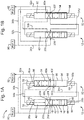
Figs. 2A-2D show schematically (in the form of a fluid flow diagram) an embodiment of the present disclosure that uses thesame pump 10 as used inFigs. 1A-1D , but in reverse sequence, such that fluid flows from the secondmain port 92 to the firstmain port 90, such that the secondmain port 92 is a fluid inlet and the firstmain port 90 is a fluid outlet. - In a first stage, as shown in
Fig. 2B , thefirst spool 14 moves within thefirst cavity 40 to expel fluid from thefirst chamber 42 to the firstmain port 90 via the second spool 54 (fluid may be conveyed through thefluid passages second chamber 44 of thefirst valve 12 from the secondmain port 92 via the spool 54 (fluid may be conveyed through thefluid passages - In a second stage, as shown in
Fig. 2C , thesecond spool 54 moves within thesecond cavity 80 to expel fluid from thesecond chamber 84 of thesecond valve 52 to the firstmain port 90 via the first spool 14 (fluid may be conveyed through thefluid passages first chamber 82 of thesecond valve 52 from the secondmain port 92 via the first spool 14 (fluid may be conveyed through thefluid passages - In a third stage, as shown in
Fig. 2D , thefirst spool 14 moves within thefirst cavity 40 to expel fluid from thesecond chamber 44 of thefirst valve 12 to the firstmain port 90 via the second spool 54 (fluid may be conveyed through thefluid passages first chamber 42 of thefirst valve 12 from the secondmain port 92 via the second spool 54 (fluid may be conveyed through thefluid passages - In a fourth stage, as shown in
Fig. 2A , thesecond spool 54 moves within thesecond cavity 80 to expel fluid from thefirst chamber 82 of thesecond valve 52 to the firstmain port 90 via the first spool 14 (fluid may be conveyed through thefluid passages second chamber 84 of thesecond valve 52 from the secondmain port 92 fire the first spool 14 (fluid may be conveyed through thefluid passages -
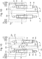
Fig. 3 shows an architecture for thepump 10 ofFigs. 1A-1D and2A-2D , although it will be appreciated that other architectures are possible. - The two
spools first valve 12 and thesecond valve 52 respectively can be seen in the cutaway portion ofFig. 3A , and are shown in their positions corresponding toFigs. 1D and2B . Eachspool first cavity first end second end spool cutaway portions 19a-d that are configured to transfer fluid between the various fluid passages depending on the axial position of thespool - For example, as shown in
Fig. 3 , afirst cutaway portion 19a fluidly connects thefluid passage 30a with thefluid passage 34d. If thefirst spool 14 were to move down, then thefirst cutaway portion 19a would instead fluidly connect thefluid passage 30a with thesefluid passage 34b. Asecond cutaway portion 19b fluidly connects thefluid passage 32b with either thefluid passage 34b (as shown inFig. 3 ) or thefluid passage 34d. Athird cutaway portion 19c fluidly connects thefluid passage 32a with either thefluid passage 34c (as shown inFig. 3 ), or thefluid passage 34a. Finally, afourth cutaway portion 19d fluidly connects thefluid passage 30b with either thefluid passage 34a (as shown inFig. 3 ), or thefluid passage 34c. - It will be appreciated that only two portions of the
fluid passages Fig. 3 . However, these passages have the same configuration as thefluid passages passage respective spool passage second cavity -
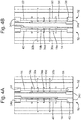
Figs. 4A-4D correspond to the sequence shown inFigs. 1A-1D (although the principles may be applied in reverse such that the sequence corresponds to that ofFigs. 2A-2D ).Fig. 4A shows thefirst spool 14 at the limit of its travel towards the secondaxial end 48 of thefirst cavity 40, and thesecond spool 54 at the limit of its travel towards the firstaxial end 86 of thesecond cavity 80. -
Fig. 4B shows thesecond spool 54 having moved to the secondaxial end 88 of thesecond cavity 80, which forces fluid previously held within thesecond cavity 84 to travel throughfluid passage 34d to thesecond cutaway portion 19b of thespool 14, so that it is onwardly conveyed to the secondmain port 92 viafluid passage 32b. At the same time, fluid from the firstmain port 90 is conveyed throughfluid passage 30a to thefirst cutaway portion 19a, so that is it is onwardly conveyed to thefirst cavity 82 of thesecond valve 52 via thefluid passage 34b. -
Fig. 4C shows thefirst spool 14 having moved to the firstaxial end 46 of thefirst cavity 40, which forces fluid previously held within thefirst cavity 42 to travel throughfluid passage 34a to thethird cutaway portion 19c of thespool 54, so that it is onwardly conveyed to the secondmain port 92 viafluid passage 32a. At the same time, fluid from the firstmain port 90 is conveyed throughfluid passage 30b to thefourth cutaway portion 19d, so that is it is onwardly conveyed to thesecond cavity 44 of thefirst valve 12 via thefluid passage 34c. -
Fig. 4D shows thespool 54 having moved to the firstaxial end 86 of thesecond cavity 80, which forces fluid previously held within thefirst cavity 82 to travel throughfluid passage 34b to thesecond cutaway portion 19b of thefirst spool 14, so that it is onwardly conveyed to the secondmain port 92 viafluid passage 32b. At the same time, fluid from the firstmain port 90 is conveyed throughfluid passage 30a to thefirst cutaway portion 19a, so that is it is onwardly conveyed to thesecond cavity 84 of thesecond valve 52 via thefluid passage 34d. -
Fig. 4A shows thefirst spool 14 having moved to the secondaxial end 48 of thefirst cavity 40, which forces fluid previously held within thesecond cavity 44 to travel throughfluid passage 34c to thethird cutaway portion 19c of thespool 54, so that it is onwardly conveyed to the secondmain port 92 viafluid passage 32a. At the same time, fluid from the firstmain port 90 is conveyed throughfluid passage 30b to thefourth cutaway portion 19d, so that is it is onwardly conveyed to thefirst cavity 42 of thefirst valve 12 via thefluid passage 34a. - The "four-stage" apparatus (or pump) described above may be used to provide a continuous outflow of fluid through the first or second
main port 90, 92 (depending on the sequence). It will be appreciated that a single valve in combination with a single spool may be provided instead of the dual- valve and spool configuration described above. - For example, an apparatus may be provided in which a single spool or a plurality of separate spools are each axially movable within respective cavities, wherein a first chamber is located at a first axial end of each cavity and a second chamber is located at a second axial end of each cavity, wherein the volume of each first chamber and each second chamber varies depending upon the axial position of each respective spool within its cavity.
- In addition, the apparatus may further comprise a single valve movable between a first position and a second position, wherein in the first position the valve is configured to convey fluid from the fluid inlet to the first chamber and from the second chamber to the fluid outlet, and in the second position the valve is configured to convey fluid from the fluid inlet to the second chamber and from the first chamber to the fluid outlet.
- It will further, and alternatively be appreciated that more valves may be provided in addition to the two that are described in the above example. For example, four valves may be provided, each comprising a spool that is driven by two actuators (providing eight actuators in total).
- The technology disclosed herein has been found to improve pump efficiency by reducing friction due to motion conversion that is otherwise exhibited in pumps that use rotary shafts and convert this rotational motion to linear movement of a piston. The efficiency is further increased by reducing internal leakage, due to the elimination of certain components such as piston shoes and valve ports. There is also a low initial force when starting the apparatus, in contrast to rotary systems that have to initiate rotation of a shaft with a high static friction.
- The life of the pump may be improved due to the low friction of the parts and high reliability of the spool and valve configuration.
- In addition, where a plurality of valves are provided there is an opportunity to provide a redundancy scenario, in which failure of one of the fluid pathways does not result in complete failure of the system. For example, a blockage in a fluid pathway in the embodiments described at
Figs. 1A-1D and2A-2D would merely result in the control system switching to the single valve embodiment discussed above, and the pump could still provide a useful output. Where even more valves are provided, for example where four valves are provided, it may be possible to maintain a continuous fluid output even in the event of multiple blockages in the system. - The pump is disclosed herein may be seen as relatively inexpensive when compared to certain conventional arrangements. For example one of the most expensive parts in a rotary pump is a piston shoe, and this part is not required in the apparatus disclosed herein. Further reductions are achieved in the elimination of bearing and seal components required to convert rotary motion to linear motion in a fluidic environment, as well as the elimination of a rotary motor.
- The actuators used in the present disclosure may be any type of linear actuator known in the art. The most common is a solenoid valve, and two may be provided at either end of the spool to move it in its respective cavity. Other possible actuators include piezoelectric actuators and memory material actuators.
- The architecture disclosed herein may be used in an electro-hydrostatic actuator ("EHA"), which is a hydraulic actuator run and controlled by an electrically powered motor assembly. Typically, these are rotary motors such as a radial piston pump, axial piston pump, bent axis pump or valve pump. As the present apparatus is able to direct a fluid flow in two opposing directions (i.e., through either the first
main port 90 or the second main port 92), the pump is disclosed herein could replace the motor of such an actuator. - In certain applications, an electro-hydrostatic actuator incorporating the pump of the present disclosure may benefit from the benefits of the pump described above. For example in operation of an aircraft, it is important to provide redundancy in the event of electrical power generation failure or control path electronics failure (or blockage of fluid parts). Given that the pump of the present disclosure is able to provide a degree of redundancy when a plurality of valves are provided, this may be used in such an application in order to achieve specification requirements for electro-hydrostatic actuators in new aircraft requirements.
- Although the present invention has been described with reference to preferred embodiments, it will be understood by those skilled in the art that various changes in form and detail may be made without departing from the scope of the invention as set forth in the accompanying claims.
Claims (12)
- An apparatus for conveying a fluid from a fluid inlet (90;92) to a fluid outlet (92;90), the apparatus comprising:a first valve (12) comprising a first spool (14), a first cavity (40), a first chamber (42) and a second chamber (44), wherein the first spool (14) is axially movable within the first cavity (40), wherein the first chamber (42) is located at a first axial end (46) of the first cavity (40) and the second chamber (44) is located at a second axial end (48) of the first cavity (40), wherein the volume of the first chamber (42) and the second chamber (44) varies depending upon the axial position of the first spool (14) within the first cavity (40); anda second valve (52) comprising a second spool (54) axially movable within a second cavity (80), wherein a first chamber (82) of the second valve (52) is located at a first axial end (86) of the second cavity (80) and a second chamber (84) of the second valve (52) is located at a second axial end (88) of the second cavity (80), wherein the volume of the first chamber (82) of the second valve (52) and the second chamber (84) of the second valve (52) varies depending upon the axial position of the second spool (54) within the second cavity (80), wherein:the second valve (52) is movable between a first position and a second position, wherein in the first position the second valve (52) is configured to convey fluid from the fluid inlet (90;92) to the first chamber (42) of the first valve (12) and from the second chamber (44) of the first valve (12) to the fluid outlet (92;90), and in the second position the second valve (52) is configured to convey fluid from the fluid inlet (90;92) to the second chamber (44) of the first valve (12) and from the first chamber (42) of the first valve (12) to the fluid outlet (92;90); andthe first valve (12) is movable between a first position and a second position, wherein in the first position the first valve (12) is configured to convey fluid from the fluid inlet (90;92) to the first chamber (82) of the second valve (52) and from the second chamber (84) of the second valve (52) to the fluid outlet (92;90), and in the second position the first valve (12) is configured to convey fluid from the fluid inlet (90;92) to the second chamber (84) of the second valve (52) and from the first chamber (82) of the second valve (52) to the fluid outlet (92;90);characterised in that:
a control system is configured to control the movement of the first spool (14) and the second valve (52) such that:(i) when the first valve (12) is in its first position the control system is configured to move the second spool (54) in a first axial direction to increase the volume of the first chamber (82) of the second valve (52) and decrease the volume of the second chamber (84) of the second valve (52), thus conveying fluid from the fluid inlet (90;92) to the first chamber (82) of the second valve (52) and from the second chamber (84) of the second valve (52) to the fluid outlet (92;90); and(ii) when the first valve (12) is in its second position the control system is configured to move the second spool (54) in a second, opposite axial direction to increase the volume of the second chamber (84) of the second valve (52) and decrease the volume of the first chamber (82) of the second valve (52), thus conveying fluid from the fluid inlet (90;92) to the second chamber (84) of the second valve (52) and from the first chamber (82) of the second valve (52) to the fluid outlet (92;90) - An apparatus as claimed in claim 1, wherein the control system is configured to synchronise the movement of the spool (14) with the second valve (52), such that:(iii) when the second valve (52) is in its first position the control system is configured to move the first spool (14) in a first axial direction to increase the volume of the first chamber (42) of the first valve (12) and decrease the volume of the second chamber (44) of the first valve (12), thus conveying fluid from the fluid inlet (90;92) to the first chamber (42) of the first valve (12) and from the second chamber (44) of the first valve (12) to the fluid outlet (92;90); and(iv) when the second valve (52) is in its second position the control system is configured to move the first spool (14) in a second, opposite axial direction to increase the volume of the second chamber (44) of the first valve (12) and decrease the volume of the first chamber (42) of the first valve (12), thus conveying fluid from the fluid inlet (90;92) to the second chamber (44) of the first valve (12) and from the first chamber (42) of the first valve (12) to the fluid outlet (92;90).
- An apparatus as claimed in claim 2, wherein:movement of the first spool (14) in the first axial direction draws fluid from the fluid inlet (90;92) into the first chamber (42) of the first valve (12), and pushes fluid from the second chamber (44) of the first valve (12) to the fluid outlet (92;90); andmovement of the first spool (14) in the second, opposite axial direction draws fluid from the fluid inlet (90;92) into the second chamber (44) of the first valve (12) and pushes fluid from the first chamber (42) of the first valve (12) to the fluid outlet (92;90).
- An apparatus as claimed in claim 1, 2 or 3, wherein the control system is configured to reciprocate the first spool (14) within the first cavity (40) and move the second valve (52) between its first position and second position, in such a manner as to provide an intermittent or regular flow of fluid through the fluid outlet (92;90).
- An apparatus as claimed in claim 4, wherein, upon reciprocation of the first spool (14) within the first cavity (40), fluid flows through the fluid outlet (92;90) alternately from the first chamber (42) of the first valve (12) and the second chamber (44) of the first valve (12).
- An apparatus as claimed in any preceding claim, further comprising one or more actuators (18) configured to move the first spool (14) within the first cavity (40), and the second valve (52) between the first position and the second position.
- An apparatus as claimed in claim 6, wherein any or all of the one or more actuators (18) comprise solenoid actuators, piezoelectric actuators or memory material actuators.
- An apparatus as claimed in any preceding claim, wherein the control system is configured to reciprocate the spools (14,54) within their respective cavities (40,80), and move the first valve (12) and the second valve (52) between their respective first and second positions, in such a manner as to provide a substantially continuous flow of fluid through the fluid outlet (92;90).
- An apparatus as claimed in claim 8, wherein the control system is configured to apply stages (i), (ii), (iii) and (iv) in a specific sequence, so as to provide a continuous flow of fluid from the fluid inlet to the fluid outlet.
- An apparatus as claimed in claim 9, wherein the sequence is (iii), (i), (iv), (ii), or the sequence is (ii), (iv), (i), (iii).
- A method of operating an apparatus as claimed in any preceding claim, the method comprising, in sequence:moving the first spool (14) to increase the volume of the first chamber (42) of the first valve (12) and decrease the volume of the second chamber (44) of the first valve (12);moving the second spool (54) to increase the volume of the first chamber (82) of the second valve (52) and decrease the volume of the second chamber (84) of the second valve (52);moving the first spool (14) to increase the volume of the second chamber (44) of the first valve (12) and decrease the volume of the first chamber (42) of the first valve (12); andmoving the second spool (54) to increase the volume of the second chamber (84) of the second valve (52) and decrease the volume of the first chamber (82) of the second valve (52).
- A method of operating an apparatus as claimed in any preceding claim, the method comprising, in sequence:moving the first spool (14) to increase the volume of the first chamber (42) of the first valve (12) and decrease the volume of the second chamber (44) of the first valve (12); andmoving the first spool (14) to increase the volume of the second chamber (44) of the first valve (12) and decrease the volume of the first chamber (42) of the first valve (12).
Priority Applications (2)
| Application Number | Priority Date | Filing Date | Title |
|---|---|---|---|
| EP17305891.8A EP3425201B1 (en) | 2017-07-07 | 2017-07-07 | Volumetric pump |
| US16/029,698 US10920770B2 (en) | 2017-07-07 | 2018-07-09 | Volumetric pump |
Applications Claiming Priority (1)
| Application Number | Priority Date | Filing Date | Title |
|---|---|---|---|
| EP17305891.8A EP3425201B1 (en) | 2017-07-07 | 2017-07-07 | Volumetric pump |
Publications (2)
| Publication Number | Publication Date |
|---|---|
| EP3425201A1 EP3425201A1 (en) | 2019-01-09 |
| EP3425201B1 true EP3425201B1 (en) | 2020-03-04 |
Family
ID=59350841
Family Applications (1)
| Application Number | Title | Priority Date | Filing Date |
|---|---|---|---|
| EP17305891.8A Active EP3425201B1 (en) | 2017-07-07 | 2017-07-07 | Volumetric pump |
Country Status (2)
| Country | Link |
|---|---|
| US (1) | US10920770B2 (en) |
| EP (1) | EP3425201B1 (en) |
Family Cites Families (14)
| Publication number | Priority date | Publication date | Assignee | Title |
|---|---|---|---|---|
| FR443698A (en) * | 1912-05-11 | 1912-09-30 | Levahn Motor C As | Twin piston pump |
| US2458294A (en) | 1945-01-17 | 1949-01-04 | Lenious G Parker | Oil distributing system |
| US2709421A (en) * | 1952-07-29 | 1955-05-31 | Gen Electric | Hydraulic amplifier |
| FR1100976A (en) * | 1954-03-11 | 1955-09-27 | Applic Hydrauliques & Electr S | Electro-hydraulic vibrator |
| US3071014A (en) * | 1959-11-13 | 1963-01-01 | Fairchild Stratos Corp | Fluid driven unit |
| US3890064A (en) * | 1973-01-11 | 1975-06-17 | Mc Donnell Douglas Corp | Reciprocating transfer pump |
| US4233002A (en) | 1978-05-09 | 1980-11-11 | Benjamin Birenbaum | Fuel injection system |
| US4368008A (en) * | 1981-02-10 | 1983-01-11 | Tadeusz Budzich | Reciprocating controls of a gas compressor using free floating hydraulically driven piston |
| US5893707A (en) * | 1994-03-03 | 1999-04-13 | Simmons; John M. | Pneumatically shifted reciprocating pump |
| US5718570A (en) * | 1995-03-20 | 1998-02-17 | Micropump Corporation | Rotary control valve for a piston pump |
| US5733105A (en) | 1995-03-20 | 1998-03-31 | Micropump, Inc. | Axial cam driven valve arrangement for an axial cam driven parallel piston pump system |
| US5564912A (en) * | 1995-09-25 | 1996-10-15 | Peck; William E. | Water driven pump |
| DE102004042208B4 (en) * | 2004-09-01 | 2014-07-17 | Volkswagen Ag | Piston pump for conveying a fluid |
| DE102015016314A1 (en) * | 2015-12-15 | 2017-06-22 | L'orange Gmbh | piston pump |
-
2017
- 2017-07-07 EP EP17305891.8A patent/EP3425201B1/en active Active
-
2018
- 2018-07-09 US US16/029,698 patent/US10920770B2/en active Active
Non-Patent Citations (1)
| Title |
|---|
| None * |
Also Published As
| Publication number | Publication date |
|---|---|
| EP3425201A1 (en) | 2019-01-09 |
| US10920770B2 (en) | 2021-02-16 |
| US20190010934A1 (en) | 2019-01-10 |
Similar Documents
| Publication | Publication Date | Title |
|---|---|---|
| US6796120B2 (en) | Electrohydraulic actuator | |
| US6751954B2 (en) | Compact hybrid actuator | |
| US7887302B2 (en) | High pressure variable displacement piston pump | |
| US8152476B2 (en) | Positive displacement pump with a working fluid and linear motor control | |
| US9133830B2 (en) | Fluid device with flexible ring | |
| CA2996159C (en) | Pressure amplifier | |
| CN116378892B (en) | Double-valve flow distribution four-quadrant radial plunger hydraulic device and working method | |
| CN115898748A (en) | Radial plunger hydraulic device for controlling double-valve flow distribution by using single-group oil way and working method | |
| CN108167152B (en) | Hydraulic drive reciprocating pump | |
| CA2487334C (en) | Rotor machine | |
| EP3425201B1 (en) | Volumetric pump | |
| US6813885B2 (en) | Electrohydraulic setting device | |
| US4286927A (en) | Hydraulic power transfer unit | |
| WO2017098250A1 (en) | Radial pumps and motors | |
| US11454226B2 (en) | Electric off-axis opposing piston linear actuator pumping system | |
| US3255707A (en) | Hydraulic pumps and motors of the displacement type | |
| US10738757B2 (en) | Variable displacement pump-motor | |
| CN111075686A (en) | Air compressor | |
| US20180209414A1 (en) | Direct actuated valve control hydraulic pump and motor | |
| CN220522940U (en) | Switching valve and hydraulic system | |
| US20170314554A1 (en) | Non-Reciprocating Hydraulic Piston Pump | |
| CN113454338B (en) | Hydraulic actuator with overpressure compensation | |
| GB2618342A (en) | A hydraulic device and a hydraulic system for controlling a hydraulic actuator | |
| RU2215186C1 (en) | Compressor with hydraulic drive | |
| EP0773346A1 (en) | Compressed gas motor |
Legal Events
| Date | Code | Title | Description |
|---|---|---|---|
| PUAI | Public reference made under article 153(3) epc to a published international application that has entered the european phase |
Free format text: ORIGINAL CODE: 0009012 |
|
| STAA | Information on the status of an ep patent application or granted ep patent |
Free format text: STATUS: THE APPLICATION HAS BEEN PUBLISHED |
|
| AK | Designated contracting states |
Kind code of ref document: A1 Designated state(s): AL AT BE BG CH CY CZ DE DK EE ES FI FR GB GR HR HU IE IS IT LI LT LU LV MC MK MT NL NO PL PT RO RS SE SI SK SM TR |
|
| AX | Request for extension of the european patent |
Extension state: BA ME |
|
| STAA | Information on the status of an ep patent application or granted ep patent |
Free format text: STATUS: REQUEST FOR EXAMINATION WAS MADE |
|
| 17P | Request for examination filed |
Effective date: 20190612 |
|
| RBV | Designated contracting states (corrected) |
Designated state(s): AL AT BE BG CH CY CZ DE DK EE ES FI FR GB GR HR HU IE IS IT LI LT LU LV MC MK MT NL NO PL PT RO RS SE SI SK SM TR |
|
| GRAP | Despatch of communication of intention to grant a patent |
Free format text: ORIGINAL CODE: EPIDOSNIGR1 |
|
| STAA | Information on the status of an ep patent application or granted ep patent |
Free format text: STATUS: GRANT OF PATENT IS INTENDED |
|
| INTG | Intention to grant announced |
Effective date: 20190917 |
|
| GRAS | Grant fee paid |
Free format text: ORIGINAL CODE: EPIDOSNIGR3 |
|
| GRAA | (expected) grant |
Free format text: ORIGINAL CODE: 0009210 |
|
| STAA | Information on the status of an ep patent application or granted ep patent |
Free format text: STATUS: THE PATENT HAS BEEN GRANTED |
|
| AK | Designated contracting states |
Kind code of ref document: B1 Designated state(s): AL AT BE BG CH CY CZ DE DK EE ES FI FR GB GR HR HU IE IS IT LI LT LU LV MC MK MT NL NO PL PT RO RS SE SI SK SM TR |
|
| REG | Reference to a national code |
Ref country code: GB Ref legal event code: FG4D |
|
| REG | Reference to a national code |
Ref country code: CH Ref legal event code: EP |
|
| REG | Reference to a national code |
Ref country code: AT Ref legal event code: REF Ref document number: 1240665 Country of ref document: AT Kind code of ref document: T Effective date: 20200315 |
|
| REG | Reference to a national code |
Ref country code: DE Ref legal event code: R096 Ref document number: 602017012542 Country of ref document: DE |
|
| REG | Reference to a national code |
Ref country code: IE Ref legal event code: FG4D |
|
| PG25 | Lapsed in a contracting state [announced via postgrant information from national office to epo] |
Ref country code: RS Free format text: LAPSE BECAUSE OF FAILURE TO SUBMIT A TRANSLATION OF THE DESCRIPTION OR TO PAY THE FEE WITHIN THE PRESCRIBED TIME-LIMIT Effective date: 20200304 Ref country code: FI Free format text: LAPSE BECAUSE OF FAILURE TO SUBMIT A TRANSLATION OF THE DESCRIPTION OR TO PAY THE FEE WITHIN THE PRESCRIBED TIME-LIMIT Effective date: 20200304 Ref country code: NO Free format text: LAPSE BECAUSE OF FAILURE TO SUBMIT A TRANSLATION OF THE DESCRIPTION OR TO PAY THE FEE WITHIN THE PRESCRIBED TIME-LIMIT Effective date: 20200604 |
|
| PGFP | Annual fee paid to national office [announced via postgrant information from national office to epo] |
Ref country code: FR Payment date: 20200623 Year of fee payment: 4 |
|
| REG | Reference to a national code |
Ref country code: NL Ref legal event code: MP Effective date: 20200304 |
|
| PG25 | Lapsed in a contracting state [announced via postgrant information from national office to epo] |
Ref country code: BG Free format text: LAPSE BECAUSE OF FAILURE TO SUBMIT A TRANSLATION OF THE DESCRIPTION OR TO PAY THE FEE WITHIN THE PRESCRIBED TIME-LIMIT Effective date: 20200604 Ref country code: HR Free format text: LAPSE BECAUSE OF FAILURE TO SUBMIT A TRANSLATION OF THE DESCRIPTION OR TO PAY THE FEE WITHIN THE PRESCRIBED TIME-LIMIT Effective date: 20200304 Ref country code: LV Free format text: LAPSE BECAUSE OF FAILURE TO SUBMIT A TRANSLATION OF THE DESCRIPTION OR TO PAY THE FEE WITHIN THE PRESCRIBED TIME-LIMIT Effective date: 20200304 Ref country code: SE Free format text: LAPSE BECAUSE OF FAILURE TO SUBMIT A TRANSLATION OF THE DESCRIPTION OR TO PAY THE FEE WITHIN THE PRESCRIBED TIME-LIMIT Effective date: 20200304 Ref country code: GR Free format text: LAPSE BECAUSE OF FAILURE TO SUBMIT A TRANSLATION OF THE DESCRIPTION OR TO PAY THE FEE WITHIN THE PRESCRIBED TIME-LIMIT Effective date: 20200605 |
|
| REG | Reference to a national code |
Ref country code: LT Ref legal event code: MG4D |
|
| PG25 | Lapsed in a contracting state [announced via postgrant information from national office to epo] |
Ref country code: NL Free format text: LAPSE BECAUSE OF FAILURE TO SUBMIT A TRANSLATION OF THE DESCRIPTION OR TO PAY THE FEE WITHIN THE PRESCRIBED TIME-LIMIT Effective date: 20200304 |
|
| PG25 | Lapsed in a contracting state [announced via postgrant information from national office to epo] |
Ref country code: LT Free format text: LAPSE BECAUSE OF FAILURE TO SUBMIT A TRANSLATION OF THE DESCRIPTION OR TO PAY THE FEE WITHIN THE PRESCRIBED TIME-LIMIT Effective date: 20200304 Ref country code: SM Free format text: LAPSE BECAUSE OF FAILURE TO SUBMIT A TRANSLATION OF THE DESCRIPTION OR TO PAY THE FEE WITHIN THE PRESCRIBED TIME-LIMIT Effective date: 20200304 Ref country code: EE Free format text: LAPSE BECAUSE OF FAILURE TO SUBMIT A TRANSLATION OF THE DESCRIPTION OR TO PAY THE FEE WITHIN THE PRESCRIBED TIME-LIMIT Effective date: 20200304 Ref country code: SK Free format text: LAPSE BECAUSE OF FAILURE TO SUBMIT A TRANSLATION OF THE DESCRIPTION OR TO PAY THE FEE WITHIN THE PRESCRIBED TIME-LIMIT Effective date: 20200304 Ref country code: IS Free format text: LAPSE BECAUSE OF FAILURE TO SUBMIT A TRANSLATION OF THE DESCRIPTION OR TO PAY THE FEE WITHIN THE PRESCRIBED TIME-LIMIT Effective date: 20200704 Ref country code: CZ Free format text: LAPSE BECAUSE OF FAILURE TO SUBMIT A TRANSLATION OF THE DESCRIPTION OR TO PAY THE FEE WITHIN THE PRESCRIBED TIME-LIMIT Effective date: 20200304 Ref country code: PT Free format text: LAPSE BECAUSE OF FAILURE TO SUBMIT A TRANSLATION OF THE DESCRIPTION OR TO PAY THE FEE WITHIN THE PRESCRIBED TIME-LIMIT Effective date: 20200729 Ref country code: ES Free format text: LAPSE BECAUSE OF FAILURE TO SUBMIT A TRANSLATION OF THE DESCRIPTION OR TO PAY THE FEE WITHIN THE PRESCRIBED TIME-LIMIT Effective date: 20200304 Ref country code: RO Free format text: LAPSE BECAUSE OF FAILURE TO SUBMIT A TRANSLATION OF THE DESCRIPTION OR TO PAY THE FEE WITHIN THE PRESCRIBED TIME-LIMIT Effective date: 20200304 |
|
| PGFP | Annual fee paid to national office [announced via postgrant information from national office to epo] |
Ref country code: DE Payment date: 20200622 Year of fee payment: 4 |
|
| REG | Reference to a national code |
Ref country code: AT Ref legal event code: MK05 Ref document number: 1240665 Country of ref document: AT Kind code of ref document: T Effective date: 20200304 |
|
| PGFP | Annual fee paid to national office [announced via postgrant information from national office to epo] |
Ref country code: IT Payment date: 20200731 Year of fee payment: 4 |
|
| REG | Reference to a national code |
Ref country code: DE Ref legal event code: R097 Ref document number: 602017012542 Country of ref document: DE |
|
| PLBE | No opposition filed within time limit |
Free format text: ORIGINAL CODE: 0009261 |
|
| STAA | Information on the status of an ep patent application or granted ep patent |
Free format text: STATUS: NO OPPOSITION FILED WITHIN TIME LIMIT |
|
| PG25 | Lapsed in a contracting state [announced via postgrant information from national office to epo] |
Ref country code: DK Free format text: LAPSE BECAUSE OF FAILURE TO SUBMIT A TRANSLATION OF THE DESCRIPTION OR TO PAY THE FEE WITHIN THE PRESCRIBED TIME-LIMIT Effective date: 20200304 Ref country code: AT Free format text: LAPSE BECAUSE OF FAILURE TO SUBMIT A TRANSLATION OF THE DESCRIPTION OR TO PAY THE FEE WITHIN THE PRESCRIBED TIME-LIMIT Effective date: 20200304 |
|
| 26N | No opposition filed |
Effective date: 20201207 |
|
| PG25 | Lapsed in a contracting state [announced via postgrant information from national office to epo] |
Ref country code: PL Free format text: LAPSE BECAUSE OF FAILURE TO SUBMIT A TRANSLATION OF THE DESCRIPTION OR TO PAY THE FEE WITHIN THE PRESCRIBED TIME-LIMIT Effective date: 20200304 Ref country code: SI Free format text: LAPSE BECAUSE OF FAILURE TO SUBMIT A TRANSLATION OF THE DESCRIPTION OR TO PAY THE FEE WITHIN THE PRESCRIBED TIME-LIMIT Effective date: 20200304 Ref country code: MC Free format text: LAPSE BECAUSE OF FAILURE TO SUBMIT A TRANSLATION OF THE DESCRIPTION OR TO PAY THE FEE WITHIN THE PRESCRIBED TIME-LIMIT Effective date: 20200304 |
|
| REG | Reference to a national code |
Ref country code: CH Ref legal event code: PL |
|
| REG | Reference to a national code |
Ref country code: BE Ref legal event code: MM Effective date: 20200731 |
|
| PG25 | Lapsed in a contracting state [announced via postgrant information from national office to epo] |
Ref country code: CH Free format text: LAPSE BECAUSE OF NON-PAYMENT OF DUE FEES Effective date: 20200731 Ref country code: LU Free format text: LAPSE BECAUSE OF NON-PAYMENT OF DUE FEES Effective date: 20200707 Ref country code: LI Free format text: LAPSE BECAUSE OF NON-PAYMENT OF DUE FEES Effective date: 20200731 Ref country code: IE Free format text: LAPSE BECAUSE OF NON-PAYMENT OF DUE FEES Effective date: 20200707 |
|
| PG25 | Lapsed in a contracting state [announced via postgrant information from national office to epo] |
Ref country code: BE Free format text: LAPSE BECAUSE OF NON-PAYMENT OF DUE FEES Effective date: 20200731 |
|
| REG | Reference to a national code |
Ref country code: DE Ref legal event code: R119 Ref document number: 602017012542 Country of ref document: DE |
|
| GBPC | Gb: european patent ceased through non-payment of renewal fee |
Effective date: 20210707 |
|
| PG25 | Lapsed in a contracting state [announced via postgrant information from national office to epo] |
Ref country code: GB Free format text: LAPSE BECAUSE OF NON-PAYMENT OF DUE FEES Effective date: 20210707 Ref country code: DE Free format text: LAPSE BECAUSE OF NON-PAYMENT OF DUE FEES Effective date: 20220201 |
|
| PG25 | Lapsed in a contracting state [announced via postgrant information from national office to epo] |
Ref country code: TR Free format text: LAPSE BECAUSE OF FAILURE TO SUBMIT A TRANSLATION OF THE DESCRIPTION OR TO PAY THE FEE WITHIN THE PRESCRIBED TIME-LIMIT Effective date: 20200304 Ref country code: MT Free format text: LAPSE BECAUSE OF FAILURE TO SUBMIT A TRANSLATION OF THE DESCRIPTION OR TO PAY THE FEE WITHIN THE PRESCRIBED TIME-LIMIT Effective date: 20200304 Ref country code: FR Free format text: LAPSE BECAUSE OF NON-PAYMENT OF DUE FEES Effective date: 20210731 Ref country code: CY Free format text: LAPSE BECAUSE OF FAILURE TO SUBMIT A TRANSLATION OF THE DESCRIPTION OR TO PAY THE FEE WITHIN THE PRESCRIBED TIME-LIMIT Effective date: 20200304 |
|
| PG25 | Lapsed in a contracting state [announced via postgrant information from national office to epo] |
Ref country code: MK Free format text: LAPSE BECAUSE OF FAILURE TO SUBMIT A TRANSLATION OF THE DESCRIPTION OR TO PAY THE FEE WITHIN THE PRESCRIBED TIME-LIMIT Effective date: 20200304 Ref country code: AL Free format text: LAPSE BECAUSE OF FAILURE TO SUBMIT A TRANSLATION OF THE DESCRIPTION OR TO PAY THE FEE WITHIN THE PRESCRIBED TIME-LIMIT Effective date: 20200304 |
|
| PG25 | Lapsed in a contracting state [announced via postgrant information from national office to epo] |
Ref country code: IT Free format text: LAPSE BECAUSE OF NON-PAYMENT OF DUE FEES Effective date: 20210707 |