EP3425192A1 - Solenoid drive for a starter for an internal combustion engine - Google Patents
Solenoid drive for a starter for an internal combustion engine Download PDFInfo
- Publication number
- EP3425192A1 EP3425192A1 EP18174031.7A EP18174031A EP3425192A1 EP 3425192 A1 EP3425192 A1 EP 3425192A1 EP 18174031 A EP18174031 A EP 18174031A EP 3425192 A1 EP3425192 A1 EP 3425192A1
- Authority
- EP
- European Patent Office
- Prior art keywords
- bypass device
- coil
- plunger
- axial
- solenoid drive
- Prior art date
- Legal status (The legal status is an assumption and is not a legal conclusion. Google has not performed a legal analysis and makes no representation as to the accuracy of the status listed.)
- Granted
Links
Images



Classifications
-
- F—MECHANICAL ENGINEERING; LIGHTING; HEATING; WEAPONS; BLASTING
- F02—COMBUSTION ENGINES; HOT-GAS OR COMBUSTION-PRODUCT ENGINE PLANTS
- F02N—STARTING OF COMBUSTION ENGINES; STARTING AIDS FOR SUCH ENGINES, NOT OTHERWISE PROVIDED FOR
- F02N11/00—Starting of engines by means of electric motors
- F02N11/08—Circuits specially adapted for starting of engines
- F02N11/087—Details of the switching means in starting circuits, e.g. relays or electronic switches
-
- F—MECHANICAL ENGINEERING; LIGHTING; HEATING; WEAPONS; BLASTING
- F02—COMBUSTION ENGINES; HOT-GAS OR COMBUSTION-PRODUCT ENGINE PLANTS
- F02N—STARTING OF COMBUSTION ENGINES; STARTING AIDS FOR SUCH ENGINES, NOT OTHERWISE PROVIDED FOR
- F02N11/00—Starting of engines by means of electric motors
- F02N11/08—Circuits specially adapted for starting of engines
- F02N11/0859—Circuits specially adapted for starting of engines specially adapted to the type of the starter motor or integrated into it
-
- F—MECHANICAL ENGINEERING; LIGHTING; HEATING; WEAPONS; BLASTING
- F02—COMBUSTION ENGINES; HOT-GAS OR COMBUSTION-PRODUCT ENGINE PLANTS
- F02N—STARTING OF COMBUSTION ENGINES; STARTING AIDS FOR SUCH ENGINES, NOT OTHERWISE PROVIDED FOR
- F02N11/00—Starting of engines by means of electric motors
- F02N11/08—Circuits specially adapted for starting of engines
- F02N11/0851—Circuits specially adapted for starting of engines characterised by means for controlling the engagement or disengagement between engine and starter, e.g. meshing of pinion and engine gear
-
- F—MECHANICAL ENGINEERING; LIGHTING; HEATING; WEAPONS; BLASTING
- F02—COMBUSTION ENGINES; HOT-GAS OR COMBUSTION-PRODUCT ENGINE PLANTS
- F02N—STARTING OF COMBUSTION ENGINES; STARTING AIDS FOR SUCH ENGINES, NOT OTHERWISE PROVIDED FOR
- F02N15/00—Other power-operated starting apparatus; Component parts, details, or accessories, not provided for in, or of interest apart from groups F02N5/00 - F02N13/00
- F02N15/006—Assembling or mounting of starting devices
-
- F—MECHANICAL ENGINEERING; LIGHTING; HEATING; WEAPONS; BLASTING
- F02—COMBUSTION ENGINES; HOT-GAS OR COMBUSTION-PRODUCT ENGINE PLANTS
- F02N—STARTING OF COMBUSTION ENGINES; STARTING AIDS FOR SUCH ENGINES, NOT OTHERWISE PROVIDED FOR
- F02N15/00—Other power-operated starting apparatus; Component parts, details, or accessories, not provided for in, or of interest apart from groups F02N5/00 - F02N13/00
- F02N15/02—Gearing between starting-engines and started engines; Engagement or disengagement thereof
- F02N15/04—Gearing between starting-engines and started engines; Engagement or disengagement thereof the gearing including disengaging toothed gears
- F02N15/06—Gearing between starting-engines and started engines; Engagement or disengagement thereof the gearing including disengaging toothed gears the toothed gears being moved by axial displacement
- F02N15/067—Gearing between starting-engines and started engines; Engagement or disengagement thereof the gearing including disengaging toothed gears the toothed gears being moved by axial displacement the starter comprising an electro-magnetically actuated lever
-
- H—ELECTRICITY
- H01—ELECTRIC ELEMENTS
- H01F—MAGNETS; INDUCTANCES; TRANSFORMERS; SELECTION OF MATERIALS FOR THEIR MAGNETIC PROPERTIES
- H01F7/00—Magnets
- H01F7/06—Electromagnets; Actuators including electromagnets
- H01F7/08—Electromagnets; Actuators including electromagnets with armatures
- H01F7/081—Magnetic constructions
-
- H—ELECTRICITY
- H01—ELECTRIC ELEMENTS
- H01F—MAGNETS; INDUCTANCES; TRANSFORMERS; SELECTION OF MATERIALS FOR THEIR MAGNETIC PROPERTIES
- H01F7/00—Magnets
- H01F7/06—Electromagnets; Actuators including electromagnets
- H01F7/08—Electromagnets; Actuators including electromagnets with armatures
- H01F7/121—Guiding or setting position of armatures, e.g. retaining armatures in their end position
-
- H—ELECTRICITY
- H01—ELECTRIC ELEMENTS
- H01F—MAGNETS; INDUCTANCES; TRANSFORMERS; SELECTION OF MATERIALS FOR THEIR MAGNETIC PROPERTIES
- H01F7/00—Magnets
- H01F7/06—Electromagnets; Actuators including electromagnets
- H01F7/08—Electromagnets; Actuators including electromagnets with armatures
- H01F7/16—Rectilinearly-movable armatures
- H01F7/1607—Armatures entering the winding
-
- F—MECHANICAL ENGINEERING; LIGHTING; HEATING; WEAPONS; BLASTING
- F02—COMBUSTION ENGINES; HOT-GAS OR COMBUSTION-PRODUCT ENGINE PLANTS
- F02N—STARTING OF COMBUSTION ENGINES; STARTING AIDS FOR SUCH ENGINES, NOT OTHERWISE PROVIDED FOR
- F02N15/00—Other power-operated starting apparatus; Component parts, details, or accessories, not provided for in, or of interest apart from groups F02N5/00 - F02N13/00
- F02N15/02—Gearing between starting-engines and started engines; Engagement or disengagement thereof
- F02N15/04—Gearing between starting-engines and started engines; Engagement or disengagement thereof the gearing including disengaging toothed gears
- F02N15/06—Gearing between starting-engines and started engines; Engagement or disengagement thereof the gearing including disengaging toothed gears the toothed gears being moved by axial displacement
- F02N15/062—Starter drives
-
- F—MECHANICAL ENGINEERING; LIGHTING; HEATING; WEAPONS; BLASTING
- F02—COMBUSTION ENGINES; HOT-GAS OR COMBUSTION-PRODUCT ENGINE PLANTS
- F02N—STARTING OF COMBUSTION ENGINES; STARTING AIDS FOR SUCH ENGINES, NOT OTHERWISE PROVIDED FOR
- F02N11/00—Starting of engines by means of electric motors
- F02N11/08—Circuits specially adapted for starting of engines
- F02N11/087—Details of the switching means in starting circuits, e.g. relays or electronic switches
- F02N2011/0874—Details of the switching means in starting circuits, e.g. relays or electronic switches characterised by said switch being an electronic switch
-
- F—MECHANICAL ENGINEERING; LIGHTING; HEATING; WEAPONS; BLASTING
- F02—COMBUSTION ENGINES; HOT-GAS OR COMBUSTION-PRODUCT ENGINE PLANTS
- F02N—STARTING OF COMBUSTION ENGINES; STARTING AIDS FOR SUCH ENGINES, NOT OTHERWISE PROVIDED FOR
- F02N11/00—Starting of engines by means of electric motors
- F02N11/08—Circuits specially adapted for starting of engines
- F02N2011/0881—Components of the circuit not provided for by previous groups
- F02N2011/0892—Two coils being used in the starting circuit, e.g. in two windings in the starting relay or two field windings in the starter
-
- F—MECHANICAL ENGINEERING; LIGHTING; HEATING; WEAPONS; BLASTING
- F02—COMBUSTION ENGINES; HOT-GAS OR COMBUSTION-PRODUCT ENGINE PLANTS
- F02N—STARTING OF COMBUSTION ENGINES; STARTING AIDS FOR SUCH ENGINES, NOT OTHERWISE PROVIDED FOR
- F02N15/00—Other power-operated starting apparatus; Component parts, details, or accessories, not provided for in, or of interest apart from groups F02N5/00 - F02N13/00
- F02N15/02—Gearing between starting-engines and started engines; Engagement or disengagement thereof
- F02N15/04—Gearing between starting-engines and started engines; Engagement or disengagement thereof the gearing including disengaging toothed gears
- F02N15/06—Gearing between starting-engines and started engines; Engagement or disengagement thereof the gearing including disengaging toothed gears the toothed gears being moved by axial displacement
- F02N2015/061—Gearing between starting-engines and started engines; Engagement or disengagement thereof the gearing including disengaging toothed gears the toothed gears being moved by axial displacement said axial displacement being limited, e.g. by using a stopper
-
- H—ELECTRICITY
- H01—ELECTRIC ELEMENTS
- H01H—ELECTRIC SWITCHES; RELAYS; SELECTORS; EMERGENCY PROTECTIVE DEVICES
- H01H51/00—Electromagnetic relays
- H01H51/02—Non-polarised relays
- H01H51/04—Non-polarised relays with single armature; with single set of ganged armatures
- H01H51/06—Armature is movable between two limit positions of rest and is moved in one direction due to energisation of an electromagnet and after the electromagnet is de-energised is returned by energy stored during the movement in the first direction, e.g. by using a spring, by using a permanent magnet, by gravity
- H01H51/065—Relays having a pair of normally open contacts rigidly fixed to a magnetic core movable along the axis of a solenoid, e.g. relays for starting automobiles
Definitions
- the present invention relates to a solenoid drive for a starter of an internal combustion engine with the features of the preamble of Claim 1.
- the invention also relates to a starter for an internal combustion engine, which starter is equipped with such a solenoid drive.
- the invention refers also to a method for operating a solenoid drive.
- a starter of this type comprises a support, an electric motor which is arranged on the support and which serves for driving a pinion in rotation, and a solenoid drive which is arranged on the support and which serves for the axial adjustment of the pinion between an engagement position, which is provided for the drive of a gearwheel of the internal combustion engine, and a non-engagement position, which is offset axially with respect to the engagement position.
- the solenoid drive used here comprises a ferromagnetic housing and a cylindrical coil arrangement which has at least one electric coil, wherein the coil arrangement is arranged in the housing and coaxially surrounds a cylindrical coil interior space. Furthermore, a ferromagnetic plunger stop is provided which is arranged at a first axial end of the coil arrangement in the housing and which has a central region projecting axially into the coil interior space.
- a ferromagnetic plunger is provided which, at a second axial end of the coil arrangement, which axial end is opposite the central region of the plunger stop, projects axially into the coil interior space, and which is arranged so as to be adjustable axially bi-directionally relative to the housing between an active position which is proximal with respect to the central region and a passive position which is distal with respect to the central region.
- the drive coupling between plunger and pinion takes place in such a manner that, in the passive position of the plunger, the pinion is in the non-engagement position while said pinion is transferred into the engagement position thereof by adjustment of the plunger into the active position.
- the solenoid drive is activated so as to transfer the pinion of the starter from the non-engagement position into the engagement position.
- the plunger is adjusted from the passive position into the active position.
- the pinion meshes with a gearwheel of the internal combustion engine, which may be formed for example on a flywheel of a drive train of the internal combustion engine.
- the electric motor then drives the pinion, which in turn drives said gearwheel, as a result of which a crankshaft of the internal combustion engine is set into rotation in order to start the internal combustion engine.
- the solenoid drive is activated such that the pinion is returned again from the engagement position into the non-engagement position.
- the plunger is adjusted back from the active position into the passive position.
- the pinion disengages from said gearwheel, that is to say no longer meshes with the latter.
- the coil arrangement has to transmit comparatively large electromagnetic forces to the plunger in order to draw the latter into the coil interior space and hold said plunger therein, for the active position. Since, for the purposes of a failsafe design, the plunger is preferably drawn into the coil interior space counter to the action of a restoring spring, comparatively high magnetic forces are required in particular to hold the plunger static in the active position, and therefore the coil arrangement is supplied with a correspondingly high level of electrical power.
- the pinion normally has a circumferential toothing with axially extending teeth.
- the gearwheel of the internal combustion engine likewise has a circumferential toothing with axially running teeth.
- the teeth of the pinion engage in toothed spaces of the gearwheel.
- axially leading tooth flanks of the teeth of the pinion do not pass directly into the toothed spaces of the toothing of the gearwheel but strike against axial tooth flanks of the teeth of the gearwheel.
- the electric motor of the starter may be activated so as to effect a rotation of the pinion as early as during the adjustment of the pinion from the non-engagement position into the engagement position.
- Said rotation for the threading-in of the pinion into the gearwheel is expediently performed with a considerably reduced torque and/or with a considerably reduced rotational speed in relation to the subsequent starting operation, when the pinion is fully engaged with the gearwheel.
- the pinion may, by way of the axially leading tooth flanks thereof, collide with the opposite axial tooth flanks of the gearwheel with corresponding intensity, increasing the wear of the toothings of pinion and gearwheel. Furthermore, the toothings may bear against one another via the axial tooth flanks with a comparatively high force, as a result of which a correspondingly high level of friction has to be overcome in order to rotate the pinion relative to the gearwheel such that the toothing of the pinion can mesh with the toothing of the gearwheel. As a result, there is the risk of increased wear here too.
- a starter of this type is known, for example, from US 8,421,565 B2 .
- said document proposes a complex construction of the coil arrangement within the solenoid drive, wherein a retraction coil for pulling the plunger into the coil interior space and a holding coil for holding the plunger that is being pulled into the coil interior space are arranged axially separately from one another.
- the plunger be equipped, on the outer circumference thereof, with an encircling annular groove which, in the passive position, is situated radially opposite an edge region circumferentially surrounding a passage opening, through which the plunger passes axially, of an end side wall of a solenoid housing.
- the circumferential groove formed on the plunger thus yields a reduction in the acting magnetic forces at the start of the retraction movement of the plunger when the pinion is to be transferred from the non-engagement position into the engagement position.
- Said known measures are, however, relatively cumbersome to realise.
- the attractive force that pulls the plunger into the coil interior space is reduced only to a comparatively small extent by the annular groove, since said annular groove ultimately merely effects a deflection of the field lines.
- the annular groove is maintained and, even when the plunger has been retracted into the coil interior space, causes a deflection of the field lines in the plunger, thus reducing the attainable magnetic forces.
- the solenoid drive which is referred to as an electromagnetic switch
- a ferromagnetic bypass device which, when the coil arrangement is energized, diverts some of the magnetic field lines directly from the plunger into the plunger stop, at least in the passive position of the plunger, such that said field lines do not extend through an air gap formed axially between the plunger and the plunger stop. Since, however, the field lines extending through said air gap are crucial for the magnetic force which drives the plunger into the coil interior space, the force acting on the plunger may be reduced for the beginning of the adjustment movement.
- the bypass device is formed by a ferromagnetic annular body which is dimensioned and arranged in the coil interior space in such a manner that said annular body extends as far as the second axial end of the coil arrangement and is supported there preferably on the housing and is in contact therewith.
- the magnetic attraction force operating on the plunger can be reduced in order to provide a soft contact when the pinion engages the gearwheel.
- the known solenoid drives provide significantly reduced magnetic attraction force from the beginning of the plunger movement until the end section of the plunger movement. In this end section of the plunger movement the magnetic attraction force increase significantly. In particular the initial forces being effective at the beginning of the plunger movement are the smallest during the complete plunger movement. Consequently, the magnetic attracting forces are only increasing form the beginning to the end of the plunger movement.
- the present invention is concerned with the problem of specifying, for a solenoid drive of the type mentioned in the introduction or for a starter equipped therewith or for an operating method, an improved or at least different embodiment which is characterized by an improved reliability especially in cold ambient conditions.
- the intention is furthermore to ensure reduced wear of the pinion and/or of the gearwheel that interacts therewith.
- the intention is to specify an advantageous or alternative way of reducing the acting magnetic forces at the start of the adjustment of the pinion from the non-engagement position into the engagement position.
- the invention is based on the general concept of dimensioning and arranging the bypass device in such a manner that said bypass device is spaced apart axially from both axial face side walls axially limiting a coil receiving chamber in which the coil arrangement is arranged. Therefore, the bypass device does not come into contact with the housing and the plunger stop for the deflection of the magnetic field lines.
- the invention makes use of the finding that for the purpose of deviating the magnetic field lines the bypass device does not need to come into contact with the housing at the face side wall which is in proximity of the plunger.
- a part of the magnetic flux is bypassing the axial gap between plunger and plunger stop by passing directly from the plunger via the bypass device to the plunger stop.
- the dimensioning and arrangement of the bypass device are undertaken in such a manner that a plunger end side facing the central region of the plunger stop is positioned axially within the bypass device in the passive position.
- said plunger end side is adjusted axially beyond the bypass device in the direction of the central region in the active position.
- the plunger end side is then located axially between the plunger stop and the bypass device.
- the bypass device and the coil arrangement are arranged in the coil receiving chamber.
- said plunger end side and/or a stop end side of the central region extend/extends planar in a plane extending perpendicular to the axial direction of the plunger.
- said local minimum can be a global minimum, i.e. the smallest value of the magnetic attracting force during the plunger movement from the passive position to the active position.
- said second local maximum can be a global maximum, i.e. the highest value of the magnetic attracting force during the plunger movement from the passive position to the active position.
- a magnetic attracting force operates on the plunger generating a movement of the plunger from the passive position to the active position.
- said magnetic attracting force only increases from the passive position. In other words, said magnetic attracting force has a minimum at the passive position.
- an axial position of the bypass device axially between the two face side walls of the coil receiving chamber, an axial height of the bypass device, and the axial overlap between the plunger and the bypass device are coordinated or adjusted in such a way, that said magnetic attracting force has a first local maximum at the passive position, then decreases from said first local maximum to a local minimum, and then increases from said local minimum to a second local maximum.
- Another improved embodiment can be achieved, when said local minimum is within a first half or within a first third of the movement of the plunger between the passive position and the active position, in particular between the first local maximum and the second local maximum.
- said local minimum is closer to the passive position than to the active position.
- the axial overlap is less than 50%, preferably less than 40%, more preferably less than a third, and more preferably less than 30%, in particular less than 25% or preferably less than 20%, of an axial height of the bypass device.
- the bypass device can be ring-shaped and can have in the circumferential direction a constant radial wall thickness and a constant axial height. With this feature manufacturing costs can be reduced.
- the bypass device can be realized in different ways.
- the bypass device can have at least one winding made from a ferromagnetic wire, or can be formed therefrom, or the bypass device can have a plurality of ferromagnetic bypass elements distributed in the circumferential direction, or the bypass device can have a ferromagnetic ring body extending in the circumferential direction continuously or with a single interruption.
- the ring body can be formed by means of a metal strip which is bent annularly such that longitudinal ends of the metal strip abut against each other and define said interruption.
- the bypass device is at a respective axial distance from the two face side walls which axial distance is at least 20% of an axial length of the coil receiving chamber.
- the axial length of the coil receiving chamber corresponds here to the axially measured distance between the two face side walls which axially limit the coil receiving chamber.
- the bypass device is arranged closer to the second face side wall such that an axial distance between the bypass device and the first face side wall is bigger than an axial distance between the bypass device and the second face side wall. More preferably, the axial distance between the bypass device and the first face side wall is as big as or bigger than the sum of the axial height of the bypass device and the axial distance between the bypass device and the second face side wall.
- bypass device can be arranged closer to the first side wall such that an axial distance between the bypass device and the second side wall is bigger than an axial distance between the bypass device and the first side wall.
- the axial distance between the bypass device and the second face side wall is as big as or bigger than the sum of the axial height of the bypass device and the axial distance between the bypass device and the first face side wall.
- the central region of the plunger stop can have an axial distance from the bypass device.
- the central region does not extend axially into the bypass device.
- said axial distance between the central region and the bypass device is bigger than the overlap.
- said axial distance between the central region and the bypass device is smaller than the axial height of the bypass device. Also this positioning and/or dimensioning of the central region supports the increase of the magnetic force after a predetermined length of the movement of the plunger, in particular when the plunger extends axially through the bypass device.
- the coil arrangement has a cylindrical coil carrier onto which the at least one coil is wound radially on the outside, and when the bypass device is in contact with said coil carrier and is arranged radially on the inside of the at least one coil.
- the bypass device is a part of the coil arrangement which can be pre-assembled and can be inserted to the solenoid drive as a whole unit.
- the bypass device can be inserted into an inner reception which is provided radially on the inside of the coil carrier such that an outer wall portion of the coil carrier is radially between the bypass device and the at least one coil.
- the bypass device can be inserted into an outer reception which is provided radially on the outside of the coil carrier such that an inner wall portion of the coil carrier is radially between the bypass device and the coil interior space.
- bypass device can be integrated into the coil carrier such that on the one hand an outer wall portion of the coil carrier is radially between the bypass device and the at least one coil, while on the other hand an inner wall portion of the coil carrier is radially between the bypass device and the coil interior space.
- the plunger stop comprises the first face side wall coaxially surrounding the central region, wherein the second face side wall is provided at the housing coaxially surrounding the plunger. This simplifies the manufacture of the solenoid drive.
- the coil carrier can have an annular step with which said coil carrier is plugged axially onto the bypass device formed by the sleeve section.
- the bypass device can therefore the used as an assembly aid for the coil arrangement.
- the bypass device can have at least one winding made from a ferromagnetic wire, or can be formed therefrom.
- the bypass device can thereby be integrated particularly simply into the coil arrangement.
- the winding of the bypass device can be wound onto the coil carrier, onto which the at least one coil of the coil arrangement is also wound.
- the bypass device can have a plurality of bypass elements which are distributed in the circumferential direction and are made from ferromagnetic material.
- a plurality of bypass elements distributed in the circumferential direction instead of an encircling, undivided annular body which is closed in the circumferential direction, the influence of the bypass device on the field lines can be varied. In particular, particularly fine coordination can thereby be realised.
- the bypass elements can be arranged in an annular support of the bypass device, which simplifies the handling of the bypass device despite there being a plurality of separate bypass elements.
- bypass elements can directly adjoin one another in the circumferential direction such that said bypass elements together again form a closed ring which is, however, divided or segmented.
- the individual bypass elements can also be arranged spaced apart from one another in the circumferential direction.
- the plunger can be guided in an axially adjustable manner radially on the inside of a cylindrical guide sleeve which is arranged coaxially on the inside of the coil arrangement and which extends from the first axial end through the coil interior space and beyond the second axial end into a guide region of the housing, through which guide region the plunger passes
- a guide sleeve of this type precise axial guidance for the plunger can be realised, as a result of which the solenoid drive has increased functional reliability.
- the solenoid drive can be equipped with an actuating rod which is connected in terms of drive to the plunger and which is guided axially through the plunger stop.
- said actuating rod On a side of the plunger stop facing away from the coil interior space, said actuating rod bears an electrically conductive contact plate, with the aid of which, in the active position of the plunger, two electric contacts are connected in an electrically conductive manner to each other for example in order to connect the electric motor of the starter to the main current supply thereof.
- the contact plate and the contacts therefore form a switch within the solenoid drive, and therefore the entire solenoid drive may also be referred to as an electromagnetic switch.
- a starter according to the invention for an internal combustion engine comprises a support, an electric motor which is arranged on the support and serves for driving a pinion in rotation, and a solenoid drive of the type described above which is arranged on the support and serves for the axial adjustment of the pinion between an engagement position, which is provided for the drive of a gearwheel of the internal combustion engine, and a non-engagement position, which is offset axially with respect to the engagement position.
- the operation method according to the invention provided a specific progression of the magnetic attraction forces acting on the plunger during its movement from the passive position to the active position.
- the magnetic attracting force operating on the plunger start in the passive position with a first local maximum and are steadily reduced during a first phase of the movement to a global minimum. Then these magnetic attracting forces operating on the plunger are steadily increased during a second phase of the movement from said minimum to a second local maximum.
- Said second local maximum may be at the active position.
- the coil arrangement comprises an attracting or pulling coil and a holding coil.
- both coils are electrically energized, i.e. excited.
- the attracting or pulling coil can be deactivated. Then only the holding coil is electrically energized and thus excited and generates the magnetic attracting force for pulling the plunger through the last distance into the active position.
- a significant drop occurs in the magnetic attracting force.
- the attracting coil is stronger or more powerful than the hodling coil.
- Said drop defines another or second local minimum from which the magnetic attracting force increases to a third local maximum at the active position.
- the second local minimum can have lower magnetic attracting forces than the first local minimum.
- Said second local minimum accordingly defines a global minimum in this case.
- the third local maximum usually is smaller than the second local maximum and preferably higher than the first local maximum. Accordingly, said second local maximum preferably defines a global maximum.
- the electrical power used to electrically energize the coil arrangement is constant.
- a constant electrical voltage is provided.
- the electric current drawn from the coil arrangement may depend from the demand of the coil arrangement and can vary according to the impedance of the coil arrangement and/or according to the actual relative position between plunger and plunger stop.
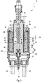
- a starter 1 which is provided for starting an internal combustion engine 2, of which only a portion of a gearwheel 3 is indicated in Fig. 1 by dashed lines, comprises a support 4, an electric motor 5 and a solenoid drive 6, which serves at the same time as a switch for actuating the electric motor 5.
- the gearwheel 3 is incorporated in a suitable manner into a drive train (not shown specifically here) of the internal combustion engine 2 such that said gearwheel is connected in terms of drive to a crankshaft of the internal combustion engine 2 if the internal combustion engine 2 is, as is preferred, a piston engine with a crankshaft.
- the gearwheel 3 may be formed on a flywheel of the drive train.
- the support 4 is designed for fastening the starter 1 to the internal combustion engine 2 or to a peripheral of the internal combustion engine 2 which may be located, for example, in a vehicle which is equipped with the internal combustion engine 2.
- the electric motor 5 is arranged on the support 4 and serves for driving a pinion 7 in rotation.
- the pinion 7 serves for driving the gearwheel 3 when the internal combustion engine 2 is intended to be started with the aid of the starter 1.
- the pinion 7, together with a drive shaft 8 on which the pinion 7 is arranged for conjoint rotation therewith, is adjustable bilinearly in an axial direction 9, which is defined by an axis of rotation 10 of the drive shaft 8 or of the electric motor 5, between a non-engagement position NES, which is shown in Fig. 1 by solid lines, and an engagement position ES, which is indicated in Fig. 1 by dashed lines.
- the pinion is assigned the reference sign 7'.
- the pinion 7' serves for driving the gearwheel 3 and thus meshes with the latter such that a rotation of the pinion 7' forces a rotation of the gearwheel 3.
- the pinion 7 is axially offset with respect to the engagement position ES, specifically to such an extent that said pinion does not mesh with the gearwheel 3. In this respect, the pinion 7 is then arranged axially spaced apart from the gearwheel 3.
- the electric motor 5 furthermore has, in the conventional manner, an external stator 11 and an internal rotor 12, wherein the rotor 12 is connected in terms of drive to the drive shaft 8 via a transmission device 13.
- the transmission device 13 may have a clutch, in particular a one-way friction clutch.
- the transmission device 13 may additionally or alternatively have a gearing 18, for example a planetary gearing.
- the stator 11 is accommodated in a stator housing 14 which is fastened to the support 4.
- the support 4 has a base housing 29, which serves for the fastening of the starter 1 to said peripheral, and an intermediate housing 15, which is fastened to the base housing 29.
- the stator housing 14 is now fastened to said intermediate housing 15.
- the drive shaft 8 is mounted by way of a main bearing 16 on the support 4 or on the base housing 29 thereof.
- a further bearing 17 is provided in the intermediate housing 15, for the purpose of mounting the drive shaft 8.
- the solenoid drive 6 has a solenoid housing 19 which is referred to below in short as housing 19 and which is fastened to the support 4, specifically to the intermediate housing 15 thereof.
- the solenoid drive 6 serves for the axial adjustment of the pinion 7.
- the solenoid drive 6 has a plunger stop 20 which is static with respect to the support 4, a plunger 21 which is axially adjustable relative to the plunger stop 20, and a cylindrical coil arrangement 22.
- An axial direction 23 of the axial adjustability of the plunger 21 is defined by a longitudinal central axis 24 of the solenoid drive 6.
- the solenoid drive 6 is expediently arranged on the support 4 so as to be parallel and adjacent to the electric motor 5, such that the longitudinal central axis 24 extends parallel to the axis of rotation 10.
- the coil arrangement 22 is arranged on the plunger stop 20 and surrounds a cylindrical coil interior space 25 in a circumferential direction, which is based on the longitudinal central axis 24.
- the plunger 21 is coupled by way of a deflecting lever 26 to the drive shaft 8 in such a manner that, for the adjustment of the pinion 7 from the non-engagement position NES into the engagement position ES, the plunger 21 is retracted into the coil interior space 25.
- the coil arrangement 22 is in the form of a retraction coil 40 which, when energised, pulls the plunger 21 into the coil interior space 25.
- the deflecting lever 26 here effects a reversal of the movement direction, such that the retraction of the plunger 21 toward the top in Fig.
- the plunger 21 is therefore adjustable with respect to the plunger stop 20 between an extended passive position PS and a retracted active position AS.
- the axial position of a plunger end side 27 facing the plunger stop 20 is indicated by solid lines for the passive position PS while the axial position of the plunger end side 27 is indicated by dashed lines for the active position AS.
- the plunger end side 27 In the active position AS, the plunger end side 27 preferably comes axially to bear against a stop end side 28 of the plunger stop 20, which stop end side 28 faces the plunger 21 and therefore forms an axial end stop for the plunger 21.
- the plunger 21 is coupled to an actuating rod 30 which, for this purpose, extends at least partially through the plunger 21.
- the actuating rod 30 serves for the axial adjustment of a plate-like contact element 31 which, for its part, serves for the electrical connection of two electric contacts 32.
- the electric motor 5 is connected to a main current supply 33 via said electric contacts 32. In other words, as soon as the contact element 31 electrically connects the two electric contacts 32 to each other, the electric motor 5 can be supplied with a rated electrical power via the main current supply 33 so that the electric motor 5 can output a rated torque at the pinion 7.
- the electric motor 5 in series with the solenoid drive 6 or with the coil arrangement 22 thereof.
- the electric motor 5 can therefore be initially supplied with a considerably lower electrical power in order to drive the pinion 7 with a considerably lower torque and/or at a considerably lower rotational speed for as long as said pinion has not yet reached the engagement position ES thereof.
- the actuating rod 30 is guided coaxially through the plunger stop 20. Accordingly, the plunger stop 20 is ultimately located axially between the plunger 21 and the contact element 31.
- the plunger 21 is assigned at least one restoring spring 34 which, in the example, loops coaxially around the actuating rod 30.
- the restoring spring 34 is supported here on one side on the plunger 21 and on the other side on the plunger stop 20.
- the restoring spring 34 protrudes here in a cavity 35 formed on the plunger 21.
- the actuating rod 30 is also assigned a restoring spring 36 which is supported on one side on the actuating rod 30 and on the other side on a contact housing 37, on which the electric contacts 32 are located. Furthermore, a pre-tensioning spring 38 can be provided which drives the contact element 31 in the direction of the contacts 32. Said pre-tensioning spring 38 is supported here on the actuating rod 30. An axial distance between the contact element 31 and the contacts 32 is discernibly smaller than the entire adjustment travel of the plunger 21 between the passive position PS and the active position AS. The contact element 31 therefore comes into contact with the contacts 32 shortly before reaching the active position AS. On reaching the active position AS, the pre-tensioning spring 38 then brings about a pre-tensioned bearing of the contact element 31 against the contacts 32.
- the rated torque builds up with a time delay.
- the coordination is expediently undertaken here in such a manner that the rated torque is present approximately synchronously with the reaching of the active position AS, i.e. also synchronously with the reaching of the engagement position ES.
- the contact element 31 bears axially against a rear side 39 of the plunger stop 20, which rear side faces away from the plunger 21.
- the solenoid drive 6 therefore also serves for the connection of the main current supply 33 of the electric motor 5, said solenoid drive may also be referred to as an electromagnetic switch.
- the solenoid drive 6 comprises the housing 19 produced from a ferromagnetic material, the coil arrangement 22, the ferromagnetic plunger stop 20 and the ferromagnetic plunger 21.
- the coil arrangement 22 in each case comprises two coils, specifically a retraction coil 40 for pulling the plunger 21 into the interior of the coil arrangement 22 counter to the plunger stop 20, and a holding coil 41 for holding the plunger 21 in the active position AS.
- the coil arrangement 22 is arranged in a coil receiving chamber 64 of the housing 19 and coaxially surrounds the coil interior space 25.
- the col receiving chamber 64 is axially limited by a first face side wall 65 and a second face side wall 66 axially opposing the first face side wall 65.
- the plunger stop 20 is arranged at a first axial end 42 of the coil arrangement 22 in the housing 19.
- the plunger stop 20 has a central region 43 which projects axially into the coil interior space 25 and has the above mentioned stop end side 28 which can serve as an axial stop for the plunger 21.
- the plunger stop 20 is provided with the first face side wall 65 which is ring shaped and coaxially encircling the central region 43.
- the second face side wall 66 is provided at the housing 19. In the depicted examples, the coil arrangement 22 axially abuts with its first axial end 42 to the first face side wall 65.
- the plunger 21 projects axially into the coil interior space 25 at a second axial end 44 of the coil arrangement 22, which second axial end 44 is opposite the central region 43.
- this second axial end 44 is axially spaced apart from the second face side wall 66.
- an axial gap 67 is provided axially between the second axial end 44 and the second face side wall 66.
- a sealing member 49 is arranged and elastically deformed in order to press the coil arrangement 22 axially against the first face side wall 65.
- the plunger 21, as explained, is arranged so as to be adjustable axially bi-directionally relative to the housing 19 between the active position AS which is proximal with respect to the central region 43 and the passive position PS which is distal with respect to the central region 43.
- an axial air gap 63 is provided within the coil interior space 25 axially between the plunger 21 or the plunger end side 27, respectively, and the plunger stop 20 or the stop end side 28, respectively.
- This axial air gap 63 reduces when the plunger 21 moves from the passive position PS to the active position AS.
- the plunger 21 can be in contact by means of the plunger end side 27 thereof with the stop end side 28 which is located on the central region 43 in the coil interior space 25. In this case the axial air gap 63 is eliminated in the active position AS.
- the solenoid drive 6 shown here is equipped with a ferromagnetic bypass device 45.
- the latter is arranged within the coil receiving chamber 64, coaxially with respect to the coil arrangement 22 and radially within the respective coil 40, 41 of the coil arrangement 22.
- the bypass device 45 brings about a deflection of magnetic field lines in such a manner that the deflected magnetic field lines are not guided within the coil interior space 25 through the axial air gap 63 prevailing there between plunger 21 and plunger stop 20, but rather pass from the plunger 21 via the bypass device 45 directly to the plunger stop 20.
- the bypass device 45 is arranged and dimensioned in such a manner that said bypass device 45 is spaced apart axially from both face side walls 65, 66 of the coil receiving chamber 64 and also from both axial ends 42, 44 of the coil arrangement 22.
- the bypass device 45 can be at a respective axial distance 46, 47 from both face side walls 65, 66, which axial distance is at least 20% of an axial length 48 of the coil receiving chamber 64.
- the axial length 48 of the coil receiving chamber 64 is discernibly defined by the axial distance between the two face side walls 65, 66.
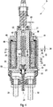
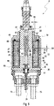
- the position and dimension of the bypass device 45 are approximately the same as in Fig. 2 .
- the bypass device 45 is formed in each case by a single cylindrical and preferably annular body.
- the bypass device 45 can be formed by a winding made from a ferromagnetic wire.
- the bypass device 45 can be formed with the aid of a plurality of ferromagnetic bypass elements which are arranged distributed in the circumferential direction. The bypass elements can be adjacent to one another in the circumferential direction or preferably arranged spaced apart from one another.
- the coil arrangement 22 has a cylindrical coil carrier 51 onto which the two coils 40, 41 are wound radially on the outside.
- the holding coil 41 is expediently wound here radially on the outside of the retraction coil 40 and extends in particular over the entire axial length of the retraction coil 40.
- the coil carrier 51 is expediently composed of a non-magnetic material.
- the coil carrier 51 has a tubular casing 50 which, at the axial ends thereof, has two annular end discs which protrude outward from the casing in the manner of collars and define the axial ends 42, 44 of the coil arrangement 22.
- the coils 40, 41 are arranged radially on the outside of the casing 50 and axially between the end discs, i.e. axial ends 42, 44.
- the bypass device 45 can now be arranged radially on the inside of the coil carrier 51, which is the case in the example of Fig. 2 .
- an inner reception 52 which forms a depression on the radial inner side of the coil carrier 51 can be formed radially on the inside of the coil carrier 51.
- the bypass device 45 is inserted in said recessed inner reception 52.
- the reception 52 extends axially only over the axial height 53 of the bypass device 45.
- the coil carrier 51 which is produced from a plastic can be sprayed or injection moulded onto the outside of the bypass device 45.
- bypass device 45 is integrated in the coil arrangement 22.
- the solenoid drive 6 is expediently provided with a cylindrical guide sleeve 57 which is arranged coaxially on the inside of the coil arrangement 22 and which extends from the first axial end 42 through the coil interior space 25 and beyond the second axial end 44 into a guide region 58 of the housing 19.
- the plunger 21 passes through said guide region 58.
- the plunger 21 is guided in an axially adjustable manner radially on the inside of said guide sleeve 57.
- Said guide sleeve 57 is expediently produced from a non-magnetic material. For example, a low-friction plastic is used.
- the dimensioning and arrangement of the bypass device 45 are undertaken in such a manner that the plunger end side 27 facing the central region 43 of the plunger stop 20 is positioned axially within the bypass device 45 in the passive position PS.
- an axial overlap 54 is provided between the plunger 21 and the bypass device 45.
- said plunger end side 27 is adjusted axially beyond the bypass device 45 in the direction of the central region 43 in the active position AS.
- the plunger end side 27 is then located axially between the plunger stop 20 and the bypass device 45.
- the bypass device 45 and the coil arrangement 22 are arranged in the coil receiving chamber 64.
- said plunger end side 27 and the stop end side 28 of the central region 43 extend planar each in a plane extending perpendicular to the axial direction 23 of the plunger 21.
- the axial overlap 54 is obviously less than 50% and in particular less than 25% of the axial height 53 of the bypass device 45.
- Said overlap 54 can be less than 40%, preferably less than 33,33%, more preferably less than 30%.
- an overlap 54 less than 20% can be of advantage. It has been determined that surprisingly good results can be achieved, when the axial overlap 54 is less than three times of a radial wall thickness 55 of the bypass device 45, more preferably, when the axial overlap 54 is less than 5mm plus the half of the radial wall thickness 55 of the bypass device 45.
- the bypass device 45 is ring-shaped and has in the circumferential direction a constant radial wall thickness 55 and a constant axial height 53.
- the bypass device 45 can have a ferromagnetic ring body 56 extending in the circumferential direction continuously or with a single interruption.
- the ring body 56 can be formed by means of a metal strip which is bent annularly such that longitudinal ends of the metal strip abut against each other and define said interruption.
- the bypass device 45 is at a respective axial distance 46, 47 from the two face side walls 65, 66.
- the bypass device 45 can be arranged closer to the second face side wall 66 such that the axial distance 46 between the bypass device 45 and the first face side wall 65 is bigger than the axial distance 47 between the bypass device 45 and the second face side wall 66.
- the axial distance 46 between the bypass device 45 and the first face side wall 65 can be as big as or even bigger than the sum of the axial height 53 of the bypass device 45 and the axial distance 47 between the bypass device 45 and the second face side wall 66.
- the bypass device 45 can be arranged completely within the axial half of the coil arrangement 22 which is facing the second face end wall 66.
- the stop end side 28 of the central region 43 of the plunger stop 20 has an axial distance 59 from the bypass device 45.
- the central region 43 does not extend axially into the bypass device 45.
- said axial distance 59 between the stop end side 28 and the bypass device 45 is bigger than the overlap 54.
- said axial distance 59 between the stop end side 28 and the bypass device 45 is smaller than the axial height 53 of the bypass device 45.
- the coil arrangement 22 has a cylindrical coil carrier 51 onto which the respective coils 40, 41 are wound radially on the outside.
- the bypass device 45 is in contact with said coil carrier 51 and is arranged radially on the inside of the coils 40, 41.
- the bypass device 45 is a part of the coil arrangement 22 which can be pre-assembled and can be inserted into the solenoid drive 6 as a whole unit or assembly.
- bypass device 45 can be inserted into an inner reception 52 which is provided radially on the inside of the coil carrier 51 such that an outer wall portion 60 of the coil carrier 51 is radially between the bypass device 45 and the coils 40, 41.
- bypass device 45 is inserted into an outer reception 61 which is provided radially on the outside of the coil carrier 51 such that an inner wall portion 62 of the coil carrier 51 is radially between the bypass device 45 and the coil interior space 25.
- bypass device 45 is integrated into the coil carrier 51 such that on the one hand an outer wall portion 60 of the coil carrier 51 is radially between the bypass device 45 and the coils 40, 41, while on the other hand an inner wall portion 62 of the coil carrier 51 is radially between the bypass device 45 and the coil interior space 25.
- Fig. 6 shows a diagram with the magnetic attracting force F on the ordinate and the plunger movement M on the abscissa.
- the values on the ordinate may be e.g. Newtons, the values on the abscissa may be e.g. millimetres.
- the diagram of Fig. 6 contains three curves or curve progressions, namely a first curve S1, a second curve S2, and a third curve S3.
- the electrical energizing of the coil arrangement 22 includes activating an attracting coil and a holding coil simultaneously.
- the coil arrangement 22 is provided with a constant electrical power.
- the attracting coil is deactivated. Therefore, a drop of the magnetic force F occurs at this switching position CS. From this switchin position on only the holding coil is active for generating the magnetic force F.
- the first curve S1 shows the progression of the magnetic attracting force F depending on the plunger movement M in a conventional solenoid drive having no bypass device.
- the magnetic attracting force F starts in the passive position PS at a relatively high level of magnetic force F.
- the magnetic force F only increases from the passive position PS to the switching position CS. In other words, said magnetic attracting force F has a minimum at the passive position PS.
- the second curve S2 shows the effect of the bypass device 45 in a conventional solenoid drive, in which the bypass-device 45 is in contact with one of the two face side walls 65, 66 and in which the overlap 54 is more than 50% of an axial height 53 of the bypass device 54.
- a conventional solenoid drive is known for example from EP 3 184 804 A1 .
- the second curve S2 of the magnetic attracting force F starts in the passive position PS at a reduced level of magnetic force F compared to the aforementioned first curve S1 of a solenoid drive having no bypass device. But also in this case, the magnetic force F only increases during the plunger movement M from the passive position PS to the switching position CS. In other words, said magnetic attracting force F also has a minimum at the passive position PS.
- an axial position of the bypass device 54 axially between the two face side walls 65, 66 of the coil receiving chamber 64, the axial height 53 of the bypass device 45, and the axial overlap 54 between the plunger 21 and the bypass device 45 are coordinated or adjusted in such a way, that said magnetic attracting force F has the third curve S3.
- the progression of the magnetic force F has a first local maximum MAX_1 at the passive position PS, then decreases from said first local maximum MAX_1 to a local minimum MIN, and then increases from said local minimum MIN to a second local maximum MAX_2.
- the second local maximum MAX_2 is in this case at the switching position CS.
- the aforementioned local minimum MIN can also be named first local minimum MIN_1.
- the respective third curve S3 shows a third local maximum MAX_3 at the active position AS.
- Another improved embodiment can be achieved, when said local minimum MIN or MIN_1 is within a first half or within a first third of the movement M of the plunger 21 between the passive position PS and the active position AS, in particular between the first local maximum MAX_1 and the second local maximum MAX_2.
- said local minimum MIN or MIN_1 is closer to the passive position PS than to the active position AS.
- the axial overlap is less than 50%, preferably less than 40%, more preferably less than a third, and more preferably less than 30%, in particular less than 25% or preferably less than 20%, of the axial height 53 of the bypass device 45.
- the overlap 54 in the passive position PS is about 20% of the axial height 53 of the bypass device 45.
- the third local maximum MAX_3 is higher than the first local maximum MAX_1 and lower than the second local maximum MAX_2.
- the second local maximum MAX_2 is higher than the first local maximum MAX_1 and higher than the third local maximum MAX_3. Consequently, the second local maximum MAX_2 defines a global maximum.
- the first local minimum MIN_1 is higher than the second local minimum MIN_2. Therefore, the second local minimum MIN_2 defines a global minimum in this case.
- the first local minimum MIN_1 can be smaller than the second local minimum MIN_2 and therefore the first local minimum MIN_1 defines a global minimum in such other case.
Landscapes
- Engineering & Computer Science (AREA)
- Physics & Mathematics (AREA)
- Electromagnetism (AREA)
- Chemical & Material Sciences (AREA)
- Combustion & Propulsion (AREA)
- Mechanical Engineering (AREA)
- General Engineering & Computer Science (AREA)
- Power Engineering (AREA)
- Electromagnets (AREA)
Abstract
Description
- The present invention relates to a solenoid drive for a starter of an internal combustion engine with the features of the preamble of
Claim 1. The invention also relates to a starter for an internal combustion engine, which starter is equipped with such a solenoid drive. The invention refers also to a method for operating a solenoid drive. - A starter of this type comprises a support, an electric motor which is arranged on the support and which serves for driving a pinion in rotation, and a solenoid drive which is arranged on the support and which serves for the axial adjustment of the pinion between an engagement position, which is provided for the drive of a gearwheel of the internal combustion engine, and a non-engagement position, which is offset axially with respect to the engagement position.
- The solenoid drive used here comprises a ferromagnetic housing and a cylindrical coil arrangement which has at least one electric coil, wherein the coil arrangement is arranged in the housing and coaxially surrounds a cylindrical coil interior space. Furthermore, a ferromagnetic plunger stop is provided which is arranged at a first axial end of the coil arrangement in the housing and which has a central region projecting axially into the coil interior space. Finally, a ferromagnetic plunger is provided which, at a second axial end of the coil arrangement, which axial end is opposite the central region of the plunger stop, projects axially into the coil interior space, and which is arranged so as to be adjustable axially bi-directionally relative to the housing between an active position which is proximal with respect to the central region and a passive position which is distal with respect to the central region. The drive coupling between plunger and pinion takes place in such a manner that, in the passive position of the plunger, the pinion is in the non-engagement position while said pinion is transferred into the engagement position thereof by adjustment of the plunger into the active position.
- For the starting of the internal combustion engine, the solenoid drive is activated so as to transfer the pinion of the starter from the non-engagement position into the engagement position. For this purpose, the plunger is adjusted from the passive position into the active position. In the engagement position, the pinion meshes with a gearwheel of the internal combustion engine, which may be formed for example on a flywheel of a drive train of the internal combustion engine. The electric motor then drives the pinion, which in turn drives said gearwheel, as a result of which a crankshaft of the internal combustion engine is set into rotation in order to start the internal combustion engine. As soon as the internal combustion engine has started and the crankshaft thereof is driven by reciprocating movements of pistons of the internal combustion engine, the solenoid drive is activated such that the pinion is returned again from the engagement position into the non-engagement position. For this purpose, the plunger is adjusted back from the active position into the passive position. In the non-engagement position, the pinion disengages from said gearwheel, that is to say no longer meshes with the latter.
- In order to be able to adjust the pinion from the non-engagement position into the engagement position and in order to be able to secure the pinion in the engagement position, the coil arrangement has to transmit comparatively large electromagnetic forces to the plunger in order to draw the latter into the coil interior space and hold said plunger therein, for the active position. Since, for the purposes of a failsafe design, the plunger is preferably drawn into the coil interior space counter to the action of a restoring spring, comparatively high magnetic forces are required in particular to hold the plunger static in the active position, and therefore the coil arrangement is supplied with a correspondingly high level of electrical power.
- The pinion normally has a circumferential toothing with axially extending teeth. Complementary with respect thereto, the gearwheel of the internal combustion engine likewise has a circumferential toothing with axially running teeth. Upon a transfer of the pinion from the non-engagement position into the engagement position, the teeth of the pinion engage in toothed spaces of the gearwheel. However, in many situations, axially leading tooth flanks of the teeth of the pinion do not pass directly into the toothed spaces of the toothing of the gearwheel but strike against axial tooth flanks of the teeth of the gearwheel. In order that the teeth of the pinion nevertheless find the toothed spaces of the gearwheel and can engage therein, the electric motor of the starter may be activated so as to effect a rotation of the pinion as early as during the adjustment of the pinion from the non-engagement position into the engagement position. Said rotation for the threading-in of the pinion into the gearwheel is expediently performed with a considerably reduced torque and/or with a considerably reduced rotational speed in relation to the subsequent starting operation, when the pinion is fully engaged with the gearwheel.
- For said two-stage starting operation, which may also be referred to as "soft-start", in the case of a starter of this type an electric series connection of the electric motor and of the solenoid drive is expediently proposed, and therefore, for the reduced driving of the electric motor, the voltage provided for energising the coil arrangement can be used in conjunction with the associated current. The solenoid drive then serves at the same time as a switch for connecting the electric motor to the actual motor current supply. In this respect, the solenoid drive at the same time forms an electromagnetic switch.
- Owing to the above-described, comparatively high magnetic force with which the plunger is drawn into the coil interior space, the pinion may, by way of the axially leading tooth flanks thereof, collide with the opposite axial tooth flanks of the gearwheel with corresponding intensity, increasing the wear of the toothings of pinion and gearwheel. Furthermore, the toothings may bear against one another via the axial tooth flanks with a comparatively high force, as a result of which a correspondingly high level of friction has to be overcome in order to rotate the pinion relative to the gearwheel such that the toothing of the pinion can mesh with the toothing of the gearwheel. As a result, there is the risk of increased wear here too.
- A starter of this type is known, for example, from
US 8,421,565 B2 . To solve the above mentioned problem, in the case of the starter, said document proposes a complex construction of the coil arrangement within the solenoid drive, wherein a retraction coil for pulling the plunger into the coil interior space and a holding coil for holding the plunger that is being pulled into the coil interior space are arranged axially separately from one another. It is also proposed that the plunger be equipped, on the outer circumference thereof, with an encircling annular groove which, in the passive position, is situated radially opposite an edge region circumferentially surrounding a passage opening, through which the plunger passes axially, of an end side wall of a solenoid housing. In this way, in the passive position, there is a radial gap between plunger and edge region. As the plunger is retracted into the coil interior space, the circumferential groove moves into the coil interior space and thereby departs from the above mentioned edge region of the end side wall, such that said edge region is subsequently situated radially opposite a plunger longitudinal section axially adjoining the circumferential groove. As the plunger is retracted, therefore, a radial distance between said edge region and an outer side of the plunger is varied, specifically reduced, as a result of which the density of the magnetic field lines transmitted from said edge region to the plunger when the coil arrangement is switched on, is varied, specifically increased. However, the density of the magnetic field lines correlates with the acting magnetic forces. The circumferential groove formed on the plunger thus yields a reduction in the acting magnetic forces at the start of the retraction movement of the plunger when the pinion is to be transferred from the non-engagement position into the engagement position. Said known measures are, however, relatively cumbersome to realise. Furthermore, the attractive force that pulls the plunger into the coil interior space is reduced only to a comparatively small extent by the annular groove, since said annular groove ultimately merely effects a deflection of the field lines. Also, the annular groove is maintained and, even when the plunger has been retracted into the coil interior space, causes a deflection of the field lines in the plunger, thus reducing the attainable magnetic forces. - Another solenoid drive or electromagnetic switch for an auxiliary-rotation starter is known form
US 8 248 193 B2 and suggests a sleeve like bypass device extending from the plunger stop to the axial end of the coil arrangement through which the plunger extends into the coil interior space. In the passive position the plunger extends essentially into the bypass device. -
DE 10 2009 052 938 A1 discloses another solution to this problem. In this document, the solenoid drive, which is referred to as an electromagnetic switch, is equipped with a ferromagnetic bypass device, which, when the coil arrangement is energized, diverts some of the magnetic field lines directly from the plunger into the plunger stop, at least in the passive position of the plunger, such that said field lines do not extend through an air gap formed axially between the plunger and the plunger stop. Since, however, the field lines extending through said air gap are crucial for the magnetic force which drives the plunger into the coil interior space, the force acting on the plunger may be reduced for the beginning of the adjustment movement. With increasing penetration depth of the plunger into the coil interior space, the diversion of the magnetic field lines by the bypass device is reduced, as a result of which the magnetic force driving the plunger increases. It has even been shown that, in the active position, the magnetic holding force which holds the plunger in the active position can be increased with the aid of such a bypass device. The same then holds true for the forces which act on the pinion and drive the pinion from the non-engagement position into the engagement position and optionally hold said pinion therein. In this known configuration a part of the magnetic flux is bypassing the axial gap between plunger and plunger stop by passing directly from the housing via the bypass device to the plunger stop. Therefore, the exact axial position of the bypass device relative to the housing and relative to the plunger stop is essential for the deviating effect. Accordingly, narrow production tolerances have to be used. - In the case of the known solenoid drive, the bypass device is formed by a ferromagnetic annular body which is dimensioned and arranged in the coil interior space in such a manner that said annular body extends as far as the second axial end of the coil arrangement and is supported there preferably on the housing and is in contact therewith.
- By means of the bypass device the magnetic attraction force operating on the plunger can be reduced in order to provide a soft contact when the pinion engages the gearwheel. The known solenoid drives provide significantly reduced magnetic attraction force from the beginning of the plunger movement until the end section of the plunger movement. In this end section of the plunger movement the magnetic attraction force increase significantly. In particular the initial forces being effective at the beginning of the plunger movement are the smallest during the complete plunger movement. Consequently, the magnetic attracting forces are only increasing form the beginning to the end of the plunger movement.
- It has been found that such solenoid drives performing the soft-start can be disadvantageous under cold ambient conditions. In cold ambient conditions lubricants show high viscosity. Moist in the air can condensate and freeze, thus ice can occur on sliding surfaces. These conditions lead to increased resistance for the movement of the plunger. The significantly reduced initial forces can be too small to overcome said increased resistance, thus the solenoid drive fails to move the pinion in place.
- The present invention is concerned with the problem of specifying, for a solenoid drive of the type mentioned in the introduction or for a starter equipped therewith or for an operating method, an improved or at least different embodiment which is characterized by an improved reliability especially in cold ambient conditions. At the same time, the intention is furthermore to ensure reduced wear of the pinion and/or of the gearwheel that interacts therewith. In particular, the intention is to specify an advantageous or alternative way of reducing the acting magnetic forces at the start of the adjustment of the pinion from the non-engagement position into the engagement position.
- This problem is solved according to the invention by the features of the independent claims. The dependent claims relate to advantageous embodiments.
- The invention is based on the general concept of dimensioning and arranging the bypass device in such a manner that said bypass device is spaced apart axially from both axial face side walls axially limiting a coil receiving chamber in which the coil arrangement is arranged. Therefore, the bypass device does not come into contact with the housing and the plunger stop for the deflection of the magnetic field lines. The invention makes use of the finding that for the purpose of deviating the magnetic field lines the bypass device does not need to come into contact with the housing at the face side wall which is in proximity of the plunger. In the invention a part of the magnetic flux is bypassing the axial gap between plunger and plunger stop by passing directly from the plunger via the bypass device to the plunger stop.
- In particular, the dimensioning and arrangement of the bypass device are undertaken in such a manner that a plunger end side facing the central region of the plunger stop is positioned axially within the bypass device in the passive position. In other words, in the passive position an axial overlap is provided between the plunger and the bypass device. On the other hand, said plunger end side is adjusted axially beyond the bypass device in the direction of the central region in the active position. In particular, the plunger end side is then located axially between the plunger stop and the bypass device. Preferably, the bypass device and the coil arrangement are arranged in the coil receiving chamber. In a preferred embodiment said plunger end side and/or a stop end side of the central region extend/extends planar in a plane extending perpendicular to the axial direction of the plunger.
- By means of this axial overlap in the passive position high initial forces can be achieved sufficient to overcome initial friction, mass inertia, resistance of lubricants especially in cold conditions. As soon as the plunger is moving this high initial forces, which represent a first local maximum, are steadily reduced by the effect of the bypass device to a local minimum. From said minimum the forces increase steadily and reach a second local maximum which preferably is higher than the first local maximum. In a preferred embodiment said local minimum can be a global minimum, i.e. the smallest value of the magnetic attracting force during the plunger movement from the passive position to the active position. According to another embodiment said second local maximum can be a global maximum, i.e. the highest value of the magnetic attracting force during the plunger movement from the passive position to the active position.
- In case the coil arrangement is electrically energized for moving the plunger from the passive position into the active position a magnetic attracting force operates on the plunger generating a movement of the plunger from the passive position to the active position. In a conventional solenoid drive said magnetic attracting force only increases from the passive position. In other words, said magnetic attracting force has a minimum at the passive position.
- According to a preferred embodiment of the present invention an axial position of the bypass device axially between the two face side walls of the coil receiving chamber, an axial height of the bypass device, and the axial overlap between the plunger and the bypass device are coordinated or adjusted in such a way, that said magnetic attracting force has a first local maximum at the passive position, then decreases from said first local maximum to a local minimum, and then increases from said local minimum to a second local maximum. By this specific arrangement a sufficient force is provided to start the movement of the plunger and the other moving parts of a starter in all operating conditions, especially cold and moist conditions. But in the main portion of the plunger movement, in which the collision of the pinion of the starter motor with the ring gear is expected, said magnetic attracting forces are significantly reduced in order to prevent pinion and gear ring wear.
- Another improved embodiment can be achieved, when said local minimum is within a first half or within a first third of the movement of the plunger between the passive position and the active position, in particular between the first local maximum and the second local maximum. In other words, said local minimum is closer to the passive position than to the active position.
- To achieve said decrease of the magnetic force at the beginning of the plunger movement, it is crucial to have a small overlap in the passive position between the plunger and the bypass device. This overlap is adjusted such that at the beginning of the plunger movement only a portion of the magnetic field lines between plunger and plunger stop can be deviated through the bypass device and the housing. Then, with an increasing overlap between plunger and bypass device more magnetic field lines can be deviated through the bypass device and the housing causing a loss of magnetic attracting force between plunger and plunger stop. At a specific overlap, this deviation effect has a maximum and thus the magnetic attracting force has said local minimum. With further increasing overlap the deviating effect decreases and the magnetic field lines tend to go directly from the plunger to the plunger stop and therefore increase correspondingly the magnetic attracting force.
- According to an embodiment the axial overlap is less than 50%, preferably less than 40%, more preferably less than a third, and more preferably less than 30%, in particular less than 25% or preferably less than 20%, of an axial height of the bypass device. With this relative small axial overlap the deviation of the magnetic flux through the bypass device can increase significantly when the plunger moves further into the bypass device. Therefore, after providing a high initial force at the beginning of the movement the force driving the plunger is significantly reduced in order to achieve the soft-start operation.
- It has been determined that surprisingly good results can be achieved, when the axial overlap is less than three times of a radial wall thickness of the bypass device, more preferably, when the axial overlap is less than 5mm plus the half of a radial wall thickness of the bypass device.
- According to a preferred embodiment the bypass device can be ring-shaped and can have in the circumferential direction a constant radial wall thickness and a constant axial height. With this feature manufacturing costs can be reduced.
- The bypass device can be realized in different ways. Preferably, the bypass device can have at least one winding made from a ferromagnetic wire, or can be formed therefrom, or the bypass device can have a plurality of ferromagnetic bypass elements distributed in the circumferential direction, or the bypass device can have a ferromagnetic ring body extending in the circumferential direction continuously or with a single interruption. For example, the ring body can be formed by means of a metal strip which is bent annularly such that longitudinal ends of the metal strip abut against each other and define said interruption.
- Another embodiment suggests that the bypass device is at a respective axial distance from the two face side walls which axial distance is at least 20% of an axial length of the coil receiving chamber. The axial length of the coil receiving chamber corresponds here to the axially measured distance between the two face side walls which axially limit the coil receiving chamber. Preferably, the bypass device is arranged closer to the second face side wall such that an axial distance between the bypass device and the first face side wall is bigger than an axial distance between the bypass device and the second face side wall. More preferably, the axial distance between the bypass device and the first face side wall is as big as or bigger than the sum of the axial height of the bypass device and the axial distance between the bypass device and the second face side wall. In an alternative embodiment the bypass device can be arranged closer to the first side wall such that an axial distance between the bypass device and the second side wall is bigger than an axial distance between the bypass device and the first side wall. In particular, the axial distance between the bypass device and the second face side wall is as big as or bigger than the sum of the axial height of the bypass device and the axial distance between the bypass device and the first face side wall. This positioning and/or dimensioning of the bypass device supports the increase of the magnetic force after a predetermined length of the movement of the plunger in order to provide the high magnetic forces needed for holding the plunger in the active position.
- According to a preferred embodiment the central region of the plunger stop can have an axial distance from the bypass device. In other words, the central region does not extend axially into the bypass device. Preferably, said axial distance between the central region and the bypass device is bigger than the overlap. Alternatively or additionally, said axial distance between the central region and the bypass device is smaller than the axial height of the bypass device. Also this positioning and/or dimensioning of the central region supports the increase of the magnetic force after a predetermined length of the movement of the plunger, in particular when the plunger extends axially through the bypass device.
- Easy manufacturing can be achieved, when the coil arrangement has a cylindrical coil carrier onto which the at least one coil is wound radially on the outside, and when the bypass device is in contact with said coil carrier and is arranged radially on the inside of the at least one coil. In this case, the bypass device is a part of the coil arrangement which can be pre-assembled and can be inserted to the solenoid drive as a whole unit.
- Preferably, the bypass device can be inserted into an inner reception which is provided radially on the inside of the coil carrier such that an outer wall portion of the coil carrier is radially between the bypass device and the at least one coil. Alternatively, the bypass device can be inserted into an outer reception which is provided radially on the outside of the coil carrier such that an inner wall portion of the coil carrier is radially between the bypass device and the coil interior space.
- Alternatively, the bypass device can be integrated into the coil carrier such that on the one hand an outer wall portion of the coil carrier is radially between the bypass device and the at least one coil, while on the other hand an inner wall portion of the coil carrier is radially between the bypass device and the coil interior space.
- Preferably, the plunger stop comprises the first face side wall coaxially surrounding the central region, wherein the second face side wall is provided at the housing coaxially surrounding the plunger. This simplifies the manufacture of the solenoid drive.
- According to an advantageous development, the coil carrier can have an annular step with which said coil carrier is plugged axially onto the bypass device formed by the sleeve section. In this case, the bypass device can therefore the used as an assembly aid for the coil arrangement.
- As mentioned above, the bypass device can have at least one winding made from a ferromagnetic wire, or can be formed therefrom. In particular, the bypass device can thereby be integrated particularly simply into the coil arrangement. For example, the winding of the bypass device can be wound onto the coil carrier, onto which the at least one coil of the coil arrangement is also wound. By this means, the coil arrangement with integrated bypass device can be produced particularly inexpensively.
- As mentioned above, the bypass device can have a plurality of bypass elements which are distributed in the circumferential direction and are made from ferromagnetic material. By means of the use of a plurality of bypass elements distributed in the circumferential direction, instead of an encircling, undivided annular body which is closed in the circumferential direction, the influence of the bypass device on the field lines can be varied. In particular, particularly fine coordination can thereby be realised. The bypass elements can be arranged in an annular support of the bypass device, which simplifies the handling of the bypass device despite there being a plurality of separate bypass elements. It is also conceivable to arrange the individual bypass elements on the coil carrier, either radially on the inside in a corresponding receiving region or radially on the outside in the region of the at least one coil. The bypass elements can directly adjoin one another in the circumferential direction such that said bypass elements together again form a closed ring which is, however, divided or segmented. Alternatively, the individual bypass elements can also be arranged spaced apart from one another in the circumferential direction.
- In an advantageous embodiment, the plunger can be guided in an axially adjustable manner radially on the inside of a cylindrical guide sleeve which is arranged coaxially on the inside of the coil arrangement and which extends from the first axial end through the coil interior space and beyond the second axial end into a guide region of the housing, through which guide region the plunger passes With the aid of a guide sleeve of this type, precise axial guidance for the plunger can be realised, as a result of which the solenoid drive has increased functional reliability.
- The solenoid drive can be equipped with an actuating rod which is connected in terms of drive to the plunger and which is guided axially through the plunger stop. On a side of the plunger stop facing away from the coil interior space, said actuating rod bears an electrically conductive contact plate, with the aid of which, in the active position of the plunger, two electric contacts are connected in an electrically conductive manner to each other for example in order to connect the electric motor of the starter to the main current supply thereof. The contact plate and the contacts therefore form a switch within the solenoid drive, and therefore the entire solenoid drive may also be referred to as an electromagnetic switch.
- A starter according to the invention for an internal combustion engine comprises a support, an electric motor which is arranged on the support and serves for driving a pinion in rotation, and a solenoid drive of the type described above which is arranged on the support and serves for the axial adjustment of the pinion between an engagement position, which is provided for the drive of a gearwheel of the internal combustion engine, and a non-engagement position, which is offset axially with respect to the engagement position.
- The operation method according to the invention provided a specific progression of the magnetic attraction forces acting on the plunger during its movement from the passive position to the active position. According to this method the magnetic attracting force operating on the plunger start in the passive position with a first local maximum and are steadily reduced during a first phase of the movement to a global minimum. Then these magnetic attracting forces operating on the plunger are steadily increased during a second phase of the movement from said minimum to a second local maximum. Said second local maximum may be at the active position. Preferably, the coil arrangement comprises an attracting or pulling coil and a holding coil. For the movement of the plunger from the passive position to the active position usually both coils are electrically energized, i.e. excited. In the last third of the plunger movement the attracting or pulling coil can be deactivated. Then only the holding coil is electrically energized and thus excited and generates the magnetic attracting force for pulling the plunger through the last distance into the active position. When the attracting coil is deactivated a significant drop occurs in the magnetic attracting force. Usually the attracting coil is stronger or more powerful than the hodling coil. Said drop defines another or second local minimum from which the magnetic attracting force increases to a third local maximum at the active position. In such a case, the second local minimum can have lower magnetic attracting forces than the first local minimum. Said second local minimum accordingly defines a global minimum in this case. Also the third local maximum usually is smaller than the second local maximum and preferably higher than the first local maximum. Accordingly, said second local maximum preferably defines a global maximum.
- It is important to understand, that during the plunger movement the electrical power used to electrically energize the coil arrangement is constant. Preferably, a constant electrical voltage is provided. The electric current drawn from the coil arrangement may depend from the demand of the coil arrangement and can vary according to the impedance of the coil arrangement and/or according to the actual relative position between plunger and plunger stop.
- Further important features and advantages of the invention will emerge from the dependent claims, from the drawings and from the associated description of the figures with reference to the drawings.
- It is self-evident that the features mentioned above and the features yet to be explained below can be used not only in the respectively stated combination, but also in other combinations or individually, without departing from the scope of the present invention.
- Preferred exemplary embodiments of the invention are illustrated in the drawings and will be explained in more detail in the description below, wherein the same reference signs relate to identical or similar or functionally identical components.
- In the drawings, in each case schematically,
- Fig. 1
- shows a side view with a partial longitudinal section of a starter with a conventional solenoid drive,
- Fig. 2 to 5
- show side views with a partial longitudinal section of a solenoid drive according to the invention of different embodiments in the region of a bypass device,
- Fig. 6
- shows a diagram in which a magnetic force is depicted depending on a movement of a plunger.
- According to
Fig. 1 , astarter 1 which is provided for starting aninternal combustion engine 2, of which only a portion of agearwheel 3 is indicated inFig. 1 by dashed lines, comprises asupport 4, anelectric motor 5 and asolenoid drive 6, which serves at the same time as a switch for actuating theelectric motor 5. Thegearwheel 3 is incorporated in a suitable manner into a drive train (not shown specifically here) of theinternal combustion engine 2 such that said gearwheel is connected in terms of drive to a crankshaft of theinternal combustion engine 2 if theinternal combustion engine 2 is, as is preferred, a piston engine with a crankshaft. For example, thegearwheel 3 may be formed on a flywheel of the drive train. - The
support 4 is designed for fastening thestarter 1 to theinternal combustion engine 2 or to a peripheral of theinternal combustion engine 2 which may be located, for example, in a vehicle which is equipped with theinternal combustion engine 2. - The
electric motor 5 is arranged on thesupport 4 and serves for driving apinion 7 in rotation. Thepinion 7 serves for driving thegearwheel 3 when theinternal combustion engine 2 is intended to be started with the aid of thestarter 1. For this purpose, thepinion 7, together with adrive shaft 8 on which thepinion 7 is arranged for conjoint rotation therewith, is adjustable bilinearly in anaxial direction 9, which is defined by an axis ofrotation 10 of thedrive shaft 8 or of theelectric motor 5, between a non-engagement position NES, which is shown inFig. 1 by solid lines, and an engagement position ES, which is indicated inFig. 1 by dashed lines. In said engagement position ES, the pinion is assigned the reference sign 7'. In the engagement position ES, the pinion 7' serves for driving thegearwheel 3 and thus meshes with the latter such that a rotation of the pinion 7' forces a rotation of thegearwheel 3. In the non-engagement position NES, thepinion 7 is axially offset with respect to the engagement position ES, specifically to such an extent that said pinion does not mesh with thegearwheel 3. In this respect, thepinion 7 is then arranged axially spaced apart from thegearwheel 3. - The
electric motor 5 furthermore has, in the conventional manner, anexternal stator 11 and aninternal rotor 12, wherein therotor 12 is connected in terms of drive to thedrive shaft 8 via atransmission device 13. Thetransmission device 13 may have a clutch, in particular a one-way friction clutch. Thetransmission device 13 may additionally or alternatively have agearing 18, for example a planetary gearing. Thestator 11 is accommodated in astator housing 14 which is fastened to thesupport 4. In the situation shown, thesupport 4 has abase housing 29, which serves for the fastening of thestarter 1 to said peripheral, and anintermediate housing 15, which is fastened to thebase housing 29. In the example shown, thestator housing 14 is now fastened to saidintermediate housing 15. - The
drive shaft 8 is mounted by way of amain bearing 16 on thesupport 4 or on thebase housing 29 thereof. A further bearing 17 is provided in theintermediate housing 15, for the purpose of mounting thedrive shaft 8. - The
solenoid drive 6 has asolenoid housing 19 which is referred to below in short ashousing 19 and which is fastened to thesupport 4, specifically to theintermediate housing 15 thereof. Thesolenoid drive 6 serves for the axial adjustment of thepinion 7. For this purpose, thesolenoid drive 6 has aplunger stop 20 which is static with respect to thesupport 4, aplunger 21 which is axially adjustable relative to theplunger stop 20, and acylindrical coil arrangement 22. Anaxial direction 23 of the axial adjustability of theplunger 21 is defined by a longitudinalcentral axis 24 of thesolenoid drive 6. Thesolenoid drive 6 is expediently arranged on thesupport 4 so as to be parallel and adjacent to theelectric motor 5, such that the longitudinalcentral axis 24 extends parallel to the axis ofrotation 10. - The
coil arrangement 22 is arranged on theplunger stop 20 and surrounds a cylindrical coilinterior space 25 in a circumferential direction, which is based on the longitudinalcentral axis 24. Theplunger 21 is coupled by way of a deflectinglever 26 to thedrive shaft 8 in such a manner that, for the adjustment of thepinion 7 from the non-engagement position NES into the engagement position ES, theplunger 21 is retracted into the coilinterior space 25. Accordingly, thecoil arrangement 22 is in the form of aretraction coil 40 which, when energised, pulls theplunger 21 into the coilinterior space 25. The deflectinglever 26 here effects a reversal of the movement direction, such that the retraction of theplunger 21 toward the top inFig. 1 effects a deployment of thepinion 7 toward the bottom inFig. 1 . Theplunger 21 is therefore adjustable with respect to theplunger stop 20 between an extended passive position PS and a retracted active position AS. InFig. 1 , the axial position of aplunger end side 27 facing theplunger stop 20 is indicated by solid lines for the passive position PS while the axial position of theplunger end side 27 is indicated by dashed lines for the active position AS. In the active position AS, theplunger end side 27 preferably comes axially to bear against astop end side 28 of theplunger stop 20, which stopend side 28 faces theplunger 21 and therefore forms an axial end stop for theplunger 21. - In addition, the
plunger 21 is coupled to anactuating rod 30 which, for this purpose, extends at least partially through theplunger 21. The actuatingrod 30 serves for the axial adjustment of a plate-like contact element 31 which, for its part, serves for the electrical connection of twoelectric contacts 32. Theelectric motor 5 is connected to a maincurrent supply 33 via saidelectric contacts 32. In other words, as soon as thecontact element 31 electrically connects the twoelectric contacts 32 to each other, theelectric motor 5 can be supplied with a rated electrical power via the maincurrent supply 33 so that theelectric motor 5 can output a rated torque at thepinion 7. In order to realise what is referred to as a "soft-start operation", provision may be made to connect theelectric motor 5 in series with thesolenoid drive 6 or with thecoil arrangement 22 thereof. Theelectric motor 5 can therefore be initially supplied with a considerably lower electrical power in order to drive thepinion 7 with a considerably lower torque and/or at a considerably lower rotational speed for as long as said pinion has not yet reached the engagement position ES thereof. - The actuating
rod 30 is guided coaxially through theplunger stop 20. Accordingly, theplunger stop 20 is ultimately located axially between theplunger 21 and thecontact element 31. Theplunger 21 is assigned at least one restoringspring 34 which, in the example, loops coaxially around the actuatingrod 30. The restoringspring 34 is supported here on one side on theplunger 21 and on the other side on theplunger stop 20. The restoringspring 34 protrudes here in acavity 35 formed on theplunger 21. - The actuating
rod 30 is also assigned a restoringspring 36 which is supported on one side on theactuating rod 30 and on the other side on acontact housing 37, on which theelectric contacts 32 are located. Furthermore, apre-tensioning spring 38 can be provided which drives thecontact element 31 in the direction of thecontacts 32. Said pre-tensioningspring 38 is supported here on theactuating rod 30. An axial distance between thecontact element 31 and thecontacts 32 is discernibly smaller than the entire adjustment travel of theplunger 21 between the passive position PS and the active position AS. Thecontact element 31 therefore comes into contact with thecontacts 32 shortly before reaching the active position AS. On reaching the active position AS, thepre-tensioning spring 38 then brings about a pre-tensioned bearing of thecontact element 31 against thecontacts 32. By means of the capacitive effect of coils/windings of theelectric motor 5, the rated torque builds up with a time delay. The coordination is expediently undertaken here in such a manner that the rated torque is present approximately synchronously with the reaching of the active position AS, i.e. also synchronously with the reaching of the engagement position ES. - Furthermore, it can be seen that, in the passive position PS, the
contact element 31 bears axially against arear side 39 of theplunger stop 20, which rear side faces away from theplunger 21. - Since the
solenoid drive 6 therefore also serves for the connection of the maincurrent supply 33 of theelectric motor 5, said solenoid drive may also be referred to as an electromagnetic switch. - According to
Figs. 2 to 5 , thesolenoid drive 6 comprises thehousing 19 produced from a ferromagnetic material, thecoil arrangement 22, theferromagnetic plunger stop 20 and theferromagnetic plunger 21. In the examples shown here, thecoil arrangement 22 in each case comprises two coils, specifically aretraction coil 40 for pulling theplunger 21 into the interior of thecoil arrangement 22 counter to theplunger stop 20, and a holdingcoil 41 for holding theplunger 21 in the active position AS. Thecoil arrangement 22 is arranged in acoil receiving chamber 64 of thehousing 19 and coaxially surrounds the coilinterior space 25. Thecol receiving chamber 64 is axially limited by a firstface side wall 65 and a secondface side wall 66 axially opposing the firstface side wall 65. - The
plunger stop 20 is arranged at a firstaxial end 42 of thecoil arrangement 22 in thehousing 19. Theplunger stop 20 has acentral region 43 which projects axially into the coilinterior space 25 and has the above mentionedstop end side 28 which can serve as an axial stop for theplunger 21. Theplunger stop 20 is provided with the firstface side wall 65 which is ring shaped and coaxially encircling thecentral region 43. The secondface side wall 66 is provided at thehousing 19. In the depicted examples, thecoil arrangement 22 axially abuts with its firstaxial end 42 to the firstface side wall 65. - The
plunger 21 projects axially into the coilinterior space 25 at a secondaxial end 44 of thecoil arrangement 22, which secondaxial end 44 is opposite thecentral region 43. In the depicted examples, this secondaxial end 44 is axially spaced apart from the secondface side wall 66. Thus anaxial gap 67 is provided axially between the secondaxial end 44 and the secondface side wall 66. In this axial gap 67 a sealingmember 49 is arranged and elastically deformed in order to press thecoil arrangement 22 axially against the firstface side wall 65. - Furthermore, the
plunger 21, as explained, is arranged so as to be adjustable axially bi-directionally relative to thehousing 19 between the active position AS which is proximal with respect to thecentral region 43 and the passive position PS which is distal with respect to thecentral region 43. In the passive position PS anaxial air gap 63 is provided within the coilinterior space 25 axially between theplunger 21 or theplunger end side 27, respectively, and the plunger stop 20 or thestop end side 28, respectively. Thisaxial air gap 63 reduces when theplunger 21 moves from the passive position PS to the active position AS. As explained, in the active position AS, theplunger 21 can be in contact by means of theplunger end side 27 thereof with thestop end side 28 which is located on thecentral region 43 in the coilinterior space 25. In this case theaxial air gap 63 is eliminated in the active position AS. - In addition, the
solenoid drive 6 shown here is equipped with aferromagnetic bypass device 45. The latter is arranged within thecoil receiving chamber 64, coaxially with respect to thecoil arrangement 22 and radially within therespective coil coil arrangement 22. In a starting region of the adjustment travel of theplunger 21, which starting region has the passive position PS, thebypass device 45 brings about a deflection of magnetic field lines in such a manner that the deflected magnetic field lines are not guided within the coilinterior space 25 through theaxial air gap 63 prevailing there betweenplunger 21 andplunger stop 20, but rather pass from theplunger 21 via thebypass device 45 directly to theplunger stop 20. This results in a reduction in the magnetic forces which drive theplunger 21 in the coilinterior space 25 in the direction of theplunger stop 20. With increasing penetration depth of theplunger 21 into thecoil arrangement 22, said deflecting influence of the deflectingdevice 45 decreases. In particular, the field lines run substantially directly within the reducedair gap 63 from theplunger 21 to theplunger stop 20 in an end region of the adjustment travel of theplunger 21, which end region contains the active position AS. - In the embodiments of
Figs. 2 to 5 thebypass device 45 is arranged and dimensioned in such a manner that saidbypass device 45 is spaced apart axially from both faceside walls coil receiving chamber 64 and also from both axial ends 42, 44 of thecoil arrangement 22. According toFig. 2 , thebypass device 45 can be at a respectiveaxial distance side walls axial length 48 of thecoil receiving chamber 64. Theaxial length 48 of thecoil receiving chamber 64 is discernibly defined by the axial distance between the twoface side walls Fig. 3 to 5 the position and dimension of thebypass device 45 are approximately the same as inFig. 2 . - In the examples of
Figs. 2 to 5 thebypass device 45 is formed in each case by a single cylindrical and preferably annular body. By contrast, in the case of another embodiment (not shown) thebypass device 45 can be formed by a winding made from a ferromagnetic wire. In the case of another embodiment (also not shown) thebypass device 45 can be formed with the aid of a plurality of ferromagnetic bypass elements which are arranged distributed in the circumferential direction. The bypass elements can be adjacent to one another in the circumferential direction or preferably arranged spaced apart from one another. - In all of the embodiments shown here, the
coil arrangement 22 has acylindrical coil carrier 51 onto which the twocoils coil 41 is expediently wound here radially on the outside of theretraction coil 40 and extends in particular over the entire axial length of theretraction coil 40. Thecoil carrier 51 is expediently composed of a non-magnetic material. In particular, thecoil carrier 51 has atubular casing 50 which, at the axial ends thereof, has two annular end discs which protrude outward from the casing in the manner of collars and define the axial ends 42, 44 of thecoil arrangement 22. Thecoils casing 50 and axially between the end discs, i.e. axial ends 42, 44. - The
bypass device 45 can now be arranged radially on the inside of thecoil carrier 51, which is the case in the example ofFig. 2 . In particular, for this purpose, aninner reception 52 which forms a depression on the radial inner side of thecoil carrier 51 can be formed radially on the inside of thecoil carrier 51. Thebypass device 45 is inserted in said recessedinner reception 52. In the example ofFig. 2 , thereception 52 extends axially only over theaxial height 53 of thebypass device 45. For example, thecoil carrier 51 which is produced from a plastic can be sprayed or injection moulded onto the outside of thebypass device 45. - In the examples of
Figs. 2 to 5 , thebypass device 45 is integrated in thecoil arrangement 22. - According to the examples of
Figs. 2 to 6 , thesolenoid drive 6 is expediently provided with acylindrical guide sleeve 57 which is arranged coaxially on the inside of thecoil arrangement 22 and which extends from the firstaxial end 42 through the coilinterior space 25 and beyond the secondaxial end 44 into aguide region 58 of thehousing 19. Theplunger 21 passes through saidguide region 58. Theplunger 21 is guided in an axially adjustable manner radially on the inside of saidguide sleeve 57. Saidguide sleeve 57 is expediently produced from a non-magnetic material. For example, a low-friction plastic is used. - In all embodiments according to
Fig. 2 to 5 the dimensioning and arrangement of thebypass device 45 are undertaken in such a manner that theplunger end side 27 facing thecentral region 43 of theplunger stop 20 is positioned axially within thebypass device 45 in the passive position PS. In other words, in the passive position PS anaxial overlap 54 is provided between theplunger 21 and thebypass device 45. On the other hand, saidplunger end side 27 is adjusted axially beyond thebypass device 45 in the direction of thecentral region 43 in the active position AS. In particular, theplunger end side 27 is then located axially between theplunger stop 20 and thebypass device 45. Preferably, thebypass device 45 and thecoil arrangement 22 are arranged in thecoil receiving chamber 64. In a preferred embodiment saidplunger end side 27 and thestop end side 28 of thecentral region 43 extend planar each in a plane extending perpendicular to theaxial direction 23 of theplunger 21. - By means of this
axial overlap 54 in the passive position PS high initial forces can be achieved sufficient to overcome initial friction, mass inertia, resistance of lubricants especially in cold conditions. According to the presented embodiments theaxial overlap 54 is obviously less than 50% and in particular less than 25% of theaxial height 53 of thebypass device 45. Saidoverlap 54 can be less than 40%, preferably less than 33,33%, more preferably less than 30%. Also anoverlap 54 less than 20% can be of advantage. It has been determined that surprisingly good results can be achieved, when theaxial overlap 54 is less than three times of aradial wall thickness 55 of thebypass device 45, more preferably, when theaxial overlap 54 is less than 5mm plus the half of theradial wall thickness 55 of thebypass device 45. - Preferably, the
bypass device 45 is ring-shaped and has in the circumferential direction a constantradial wall thickness 55 and a constantaxial height 53. To this end, thebypass device 45 can have aferromagnetic ring body 56 extending in the circumferential direction continuously or with a single interruption. For example, thering body 56 can be formed by means of a metal strip which is bent annularly such that longitudinal ends of the metal strip abut against each other and define said interruption. - As discussed above the
bypass device 45 is at a respectiveaxial distance face side walls bypass device 45 can be arranged closer to the secondface side wall 66 such that theaxial distance 46 between thebypass device 45 and the firstface side wall 65 is bigger than theaxial distance 47 between thebypass device 45 and the secondface side wall 66. More preferably, theaxial distance 46 between thebypass device 45 and the firstface side wall 65 can be as big as or even bigger than the sum of theaxial height 53 of thebypass device 45 and theaxial distance 47 between thebypass device 45 and the secondface side wall 66. In other words, thebypass device 45 can be arranged completely within the axial half of thecoil arrangement 22 which is facing the secondface end wall 66. - According to a preferred embodiment the
stop end side 28 of thecentral region 43 of theplunger stop 20 has anaxial distance 59 from thebypass device 45. In other words, thecentral region 43 does not extend axially into thebypass device 45. Preferably, saidaxial distance 59 between thestop end side 28 and thebypass device 45 is bigger than theoverlap 54. Alternatively or additionally, saidaxial distance 59 between thestop end side 28 and thebypass device 45 is smaller than theaxial height 53 of thebypass device 45. - As mentioned before, the
coil arrangement 22 has acylindrical coil carrier 51 onto which therespective coils bypass device 45 is in contact with saidcoil carrier 51 and is arranged radially on the inside of thecoils bypass device 45 is a part of thecoil arrangement 22 which can be pre-assembled and can be inserted into thesolenoid drive 6 as a whole unit or assembly. - In
Fig. 2 thebypass device 45 can be inserted into aninner reception 52 which is provided radially on the inside of thecoil carrier 51 such that anouter wall portion 60 of thecoil carrier 51 is radially between thebypass device 45 and thecoils - In
Fig. 4 and5 thebypass device 45 is inserted into an outer reception 61 which is provided radially on the outside of thecoil carrier 51 such that aninner wall portion 62 of thecoil carrier 51 is radially between thebypass device 45 and the coilinterior space 25. - In
Fig. 3 thebypass device 45 is integrated into thecoil carrier 51 such that on the one hand anouter wall portion 60 of thecoil carrier 51 is radially between thebypass device 45 and thecoils inner wall portion 62 of thecoil carrier 51 is radially between thebypass device 45 and the coilinterior space 25. - In case the
coil arrangement 22 is electrically energized for moving theplunger 21 from the passive position PS into the active position AS a magnetic attracting force F operates on theplunger 21 generating a movement M of theplunger 21 from the passive position PS to the active position AS.Fig. 6 shows a diagram with the magnetic attracting force F on the ordinate and the plunger movement M on the abscissa. The values on the ordinate may be e.g. Newtons, the values on the abscissa may be e.g. millimetres. The diagram ofFig. 6 contains three curves or curve progressions, namely a first curve S1, a second curve S2, and a third curve S3. - In the examples depicted in
Fig. 6 the electrical energizing of thecoil arrangement 22 includes activating an attracting coil and a holding coil simultaneously. Thecoil arrangement 22 is provided with a constant electrical power. At a position CS, which can bei in the last quarter of the plunger movement M, the attracting coil is deactivated. Therefore, a drop of the magnetic force F occurs at this switching position CS. From this switchin position on only the holding coil is active for generating the magnetic force F. - The first curve S1 shows the progression of the magnetic attracting force F depending on the plunger movement M in a conventional solenoid drive having no bypass device. The magnetic attracting force F starts in the passive position PS at a relatively high level of magnetic force F. During the plunger movement M the magnetic force F only increases from the passive position PS to the switching position CS. In other words, said magnetic attracting force F has a minimum at the passive position PS.
- The second curve S2 shows the effect of the
bypass device 45 in a conventional solenoid drive, in which the bypass-device 45 is in contact with one of the twoface side walls overlap 54 is more than 50% of anaxial height 53 of thebypass device 54. Such a conventional solenoid drive is known for example fromEP 3 184 804 A1 - According to solenoid drive 6 presented in this description an axial position of the
bypass device 54 axially between the twoface side walls coil receiving chamber 64, theaxial height 53 of thebypass device 45, and theaxial overlap 54 between theplunger 21 and thebypass device 45 are coordinated or adjusted in such a way, that said magnetic attracting force F has the third curve S3. In this third curve S3 the progression of the magnetic force F has a first local maximum MAX_1 at the passive position PS, then decreases from said first local maximum MAX_1 to a local minimum MIN, and then increases from said local minimum MIN to a second local maximum MAX_2. The second local maximum MAX_2 is in this case at the switching position CS. Due to the drop of the magnetic force F at the switching position CS another local minimum occurs, which can be named second local minimum MIN_2. Consequently, the aforementioned local minimum MIN can also be named first local minimum MIN_1. Furthermore, the respective third curve S3 shows a third local maximum MAX_3 at the active position AS. - By this specific arrangement a sufficient force F is provided to start the movement M of the
plunger 21 and the other moving parts of astarter 1 in all operating conditions, especially cold and moist conditions. But in the main portion of the plunger movement M, in which the collision of thepinion 7 of thestarter 1 with the ring gear orgearwheel 3 is expected, said magnetic attracting force F is significantly reduced in order to prevent wear of saidpinion 7 and saidgearwheel 3. - Another improved embodiment can be achieved, when said local minimum MIN or MIN_1 is within a first half or within a first third of the movement M of the
plunger 21 between the passive position PS and the active position AS, in particular between the first local maximum MAX_1 and the second local maximum MAX_2. In other words, said local minimum MIN or MIN_1 is closer to the passive position PS than to the active position AS. - To achieve said decrease of the magnetic force F at the beginning of the plunger movement M, it is crucial to have a
small overlap 54 in the passive position PS between theplunger 21 and thebypass device 45. Thisoverlap 54 is adjusted such that at the beginning of the plunger movement M only a portion of magnetic field lines betweenplunger 21 and plunger stop 20 can be deviated through thebypass device 45 and thehousing 19. Then, with an increasingoverlap 54 betweenplunger 21 andbypass device 45 more magnetic field lines can be deviated through thebypass device 45 and thehousing 19 causing a loss of magnetic attracting force F betweenplunger 21 andplunger stop 20. At aspecific overlap 54, this deviation effect has a maximum and thus the magnetic attracting force F has said local minimum MIN. With further increasingoverlap 54 the deviating effect decreases and the magnetic field lines tend to go directly from theplunger 21 to theplunger stop 20 and therefore increase correspondingly the magnetic attracting force F. - As mentioned above the axial overlap is less than 50%, preferably less than 40%, more preferably less than a third, and more preferably less than 30%, in particular less than 25% or preferably less than 20%, of the
axial height 53 of thebypass device 45. In the depicted examples theoverlap 54 in the passive position PS is about 20% of theaxial height 53 of thebypass device 45. - In the preferred example of
Fig. 6 , the third local maximum MAX_3 is higher than the first local maximum MAX_1 and lower than the second local maximum MAX_2. The second local maximum MAX_2 is higher than the first local maximum MAX_1 and higher than the third local maximum MAX_3. Consequently, the second local maximum MAX_2 defines a global maximum. - In the case depicted in
Fig. 6 the first local minimum MIN_1 is higher than the second local minimum MIN_2. Therefore, the second local minimum MIN_2 defines a global minimum in this case. In another embodiment, the first local minimum MIN_1 can be smaller than the second local minimum MIN_2 and therefore the first local minimum MIN_1 defines a global minimum in such other case.
Claims (17)
- Solenoid drive for a starter (1),- with a ferromagnetic housing (19) which comprises a coil receiving chamber (64) axially limited by a first face side wall (65) and an opposing second face side wall (66),- with a cylindrical coil arrangement (22) which has at least one electric coil (40, 41), and which is arranged in the coil receiving chamber (64) and which coaxially surrounds a cylindrical coil interior space (25),- with a ferromagnetic plunger stop (20) which comprises a central region (43) projecting axially in the coil interior space (25),- with a ferromagnetic plunger (21) which is arranged at the housing (19) opposing the plunger stop (20), which projects axially into the coil interior space (25), and which is arranged so as to be adjustable axially bi-directionally relative to the housing (19) between an active position (AS) which is proximal with respect to the central region (43) and a passive position (PS) which is distal with respect to the central region (43), and- with a ferromagnetic bypass device (45) which extends in the circumferential direction and which is arranged coaxially with respect to the coil arrangement (22) and radially within the at least one coil (40, 41),characterized in- that the bypass device (45) is spaced apart axially from the two face side walls (65, 66), and- that in the passive position (PS) the plunger (21) projects axially into the bypass device (45) such that an axial overlap (54) between the plunger (21) and the bypass device (45) is defined.
- Solenoid drive according to Claim 1,
characterized in- that in case the coil arrangement (22) is electrically energized for moving the plunger (21) from the passive position (PS) to the active position (AS) a magnetic attracting force (F) operates on the plunger (21) moving the plunger (21) from the passive position (PS) to the active position (AS),- that an axial position of the bypass device (45) axially between the two face side walls (65, 66), an axial height (53) of the bypass device (45), and the axial overlap (54) are coordinated in such a way, that said magnetic attracting force (F) has a first local maximum (MAX_1) at the passive position (PS), decreases from said first local maximum (MAX_1) to a local minimum (MIN), and then increases from said local minimum (MIN) to a second local maximum (MAX_2). - Solenoid drive according to Claim 2,
characterized in
that said local minimum (MIN) is within a first half or within a first third of the movement (M) of the plunger (21) between the passive position (PS) and the active position (AS). - Solenoid drive according to any one of Claims 1 to 3,
characterized in
that the axial overlap (54) is less than 50% or less than 40% or less than a third or less than 30% or less than 25% or less than 20 % of an axial height (53) of the bypass device (45). - Solenoid drive according to any one of Claims 1 to 4,
characterized in
that the axial overlap (54) is less than three times of a radial wall thickness (55) of the bypass device (45). - Solenoid drive according to any one of Claims 1 to 5,
characterized in
that the axial overlap (54) is less than 5mm plus the half of a radial wall thickness (55) of the bypass device (45). - Solenoid drive according to any one of Claims 1 to 6,
characterized in
that the bypass device (45) is ring-shaped and has in the circumferential direction a constant radial wall thickness (55) and a constant axial height (53). - Solenoid drive according to any one of Claims 1 to 7,
characterized in- that the bypass device (45) has at least one winding made from a ferromagnetic wire, or is formed therefrom, or- that the bypass device (45) has a plurality of ferromagnetic bypass elements distributed in the circumferential direction, or- that the bypass device (45) has a ferromagnetic ring body (56) extending in the circumferential direction continuously or with a single interruption. - Solenoid drive according to any one of Claims 1 to 8,
characterized in
that the bypass device (45) is at a respective axial distance (46, 47) from the two face side walls (65, 66), which axial distance (46, 47) is at least 20% of an axial length (48) of the coil receiving chamber (64). - Solenoid drive according to any one of Claims 1 to 9,
characterized in- that the bypass device (45) is arranged closer to the second side wall (66) such that an axial distance (46) between the bypass device (45) and the first side wall (65) is bigger than an axial distance (47) between the bypass device (45) and the second side wall (66), or- that the bypass device (45) is arranged closer to the first side wall (65) such that an axial distance (47) between the bypass device (45) and the second side wall (66) is bigger than an axial distance (46) between the bypass device (45) and the first side wall (65). - Solenoid drive according to any one of Claims 1 to 10,
characterized in
that the central region (43) of the plunger stop (20) has an axial distance (59) from the bypass device (45). - Solenoid drive according to Claim 11,
characterized in
that the axial distance (59) between the central region (43) and the bypass device (45) is bigger than the overlap (54). - Solenoid drive according to Claim 11 or 12,
characterized in
that the axial distance (59) between the central region (43) and the bypass device (45) is smaller than the axial height (53) of the bypass device (45). - Solenoid drive according to any one of Claims 1 to 13,
characterized in- that the coil arrangement (22) has a cylindrical coil carrier (51) onto which the at least one coil (40, 41) is wound radially on the outside,- that the bypass device (45) is in contact with said coil carrier (51) and is arranged radially on the inside of the at least one coil (40, 41). - Solenoid drive according to Claim 14,
characterized in- that the bypass device (45) is inserted into a reception (52) which is provided radially on the inside of the coil carrier (51) such that an outer portion (60) of the coil carrier (51) is radially between the bypass device (45) and the at least one coil (40, 41), or- that the bypass device (45) is inserted into a reception (61) which is provided radially on the outside of the coil carrier (51) such that an inner portion (62) of the coil carrier (51) is radially between the bypass device (45) and the coil interior space (25), or- that the bypass device (45) is integrated into the coil carrier (51) such that an outer portion (60) of the coil carrier (51) is radially between the bypass device (45) and the at least one coil (40, 41) and that an inner portion (62) of the coil carrier (51) is radially between the bypass device (45) and the coil interior space (25). - Solenoid drive according to any one of Claims 1 to 15,
characterized in
that the plunger (21) is guided in an axially adjustable manner radially on the inside of a cylindrical guide sleeve (57) which is arranged coaxially on the inside of the coil arrangement (22) and which extends from the first axial end (42) through the coil interior space (25) and beyond the second axial end (44) into a guide region (58) of the housing (19), through which guide region the plunger (21) passes. - Method for operating a solenoid drive (6) of a starter (1),
wherein for moving the plunger (21) from the passive position (PS) into the active position (AS) the magnetic attracting force operating on the plunger (21) is steadily reduced during a first phase of the movement from the passive position (PS) and then steadily increased during a second phase of the movement.
Applications Claiming Priority (1)
| Application Number | Priority Date | Filing Date | Title |
|---|---|---|---|
| EP17174017 | 2017-06-01 |
Publications (2)
| Publication Number | Publication Date |
|---|---|
| EP3425192A1 true EP3425192A1 (en) | 2019-01-09 |
| EP3425192B1 EP3425192B1 (en) | 2024-01-17 |
Family
ID=59034461
Family Applications (1)
| Application Number | Title | Priority Date | Filing Date |
|---|---|---|---|
| EP18174031.7A Active EP3425192B1 (en) | 2017-06-01 | 2018-05-24 | Solenoid drive for a starter for an internal combustion engine |
Country Status (3)
| Country | Link |
|---|---|
| US (1) | US10927806B2 (en) |
| EP (1) | EP3425192B1 (en) |
| CN (1) | CN108979930B (en) |
Families Citing this family (2)
| Publication number | Priority date | Publication date | Assignee | Title |
|---|---|---|---|---|
| JP6407486B2 (en) * | 2016-04-26 | 2018-10-17 | 三菱電機株式会社 | Electromagnetic switch device for starter |
| CN121889879A (en) * | 2023-09-19 | 2026-04-17 | 森萨塔科技公司 | Controlling the speed of a movable component in an electronic relay |
Citations (4)
| Publication number | Priority date | Publication date | Assignee | Title |
|---|---|---|---|---|
| US20100271155A1 (en) * | 2009-04-28 | 2010-10-28 | Mitsubishi Electric Corporation | Electromagnetic switch for auxiliary-rotation starter |
| EP2858075A1 (en) * | 2013-10-03 | 2015-04-08 | Hamilton Sundstrand Corporation | Flux bypass for solenoid actuator |
| WO2015072770A1 (en) * | 2013-11-14 | 2015-05-21 | 발레오전장시스템스코리아 주식회사 | Magnet switch for start motor |
| EP3184804A1 (en) * | 2015-12-22 | 2017-06-28 | Mahle International GmbH | Solenoid drive for a starter for an internal combustion engine |
Family Cites Families (6)
| Publication number | Priority date | Publication date | Assignee | Title |
|---|---|---|---|---|
| US6392516B1 (en) * | 1998-12-04 | 2002-05-21 | Tlx Technologies | Latching solenoid with improved pull force |
| US8421565B2 (en) | 2010-09-21 | 2013-04-16 | Remy Technologies Llc | Starter motor solenoid with variable reluctance plunger |
| DE102011086201A1 (en) | 2011-11-11 | 2013-05-16 | Mahle International Gmbh | Fuel injection system and preheater |
| JP5910373B2 (en) * | 2012-07-11 | 2016-04-27 | 株式会社デンソー | Electromagnetic solenoid device for starter |
| DE102012223836A1 (en) * | 2012-12-19 | 2014-06-26 | Robert Bosch Gmbh | Solenoid used for starters, has yoke core that is connected with armature through radial path of magnetic circuit, and is axially provided with movably supported core portion |
| CN104347316B (en) * | 2013-07-26 | 2018-10-26 | 索恩格汽车部件德国有限公司 | Electromagnetic switch and starter |
-
2018
- 2018-05-24 EP EP18174031.7A patent/EP3425192B1/en active Active
- 2018-05-31 CN CN201810551626.XA patent/CN108979930B/en not_active Expired - Fee Related
- 2018-05-31 US US15/995,107 patent/US10927806B2/en not_active Expired - Fee Related
Patent Citations (4)
| Publication number | Priority date | Publication date | Assignee | Title |
|---|---|---|---|---|
| US20100271155A1 (en) * | 2009-04-28 | 2010-10-28 | Mitsubishi Electric Corporation | Electromagnetic switch for auxiliary-rotation starter |
| EP2858075A1 (en) * | 2013-10-03 | 2015-04-08 | Hamilton Sundstrand Corporation | Flux bypass for solenoid actuator |
| WO2015072770A1 (en) * | 2013-11-14 | 2015-05-21 | 발레오전장시스템스코리아 주식회사 | Magnet switch for start motor |
| EP3184804A1 (en) * | 2015-12-22 | 2017-06-28 | Mahle International GmbH | Solenoid drive for a starter for an internal combustion engine |
Also Published As
| Publication number | Publication date |
|---|---|
| US20180347536A1 (en) | 2018-12-06 |
| CN108979930B (en) | 2021-06-18 |
| EP3425192B1 (en) | 2024-01-17 |
| CN108979930A (en) | 2018-12-11 |
| US10927806B2 (en) | 2021-02-23 |
Similar Documents
| Publication | Publication Date | Title |
|---|---|---|
| US10316813B2 (en) | Solenoid drive for a starter for an internal combustion engine | |
| US9184646B2 (en) | Starter machine system and method | |
| US20140260792A1 (en) | Starter | |
| EP3425192B1 (en) | Solenoid drive for a starter for an internal combustion engine | |
| JP2014027202A (en) | Linear solenoid | |
| US9938950B2 (en) | Engine starting apparatus | |
| CN103511152B (en) | For the starter relay of starting arrangement | |
| JP5765974B2 (en) | Starter | |
| JP2012087765A (en) | Starter | |
| EP3617495B1 (en) | Electromagnetic switch | |
| CN105275704B (en) | Electromagnetic relay, the starter relay in particular for starting device | |
| US10337484B2 (en) | Starter for an internal combustion engine | |
| JP5720637B2 (en) | Linear solenoid | |
| EP3350435B1 (en) | Starter for an internal combustion engine | |
| JP2014027205A (en) | Linear solenoid | |
| CN104047790B (en) | Starting device for internal combustion engine | |
| JP3660394B2 (en) | Engine starter | |
| KR19980042883A (en) | Coaxial engine starter | |
| JP3751691B2 (en) | Engine starter | |
| CN112087098A (en) | Starter motor for a starter device for starting an internal combustion engine | |
| WO2017118993A1 (en) | Starter for an internal combustion engine provided with a conical spring |
Legal Events
| Date | Code | Title | Description |
|---|---|---|---|
| PUAI | Public reference made under article 153(3) epc to a published international application that has entered the european phase |
Free format text: ORIGINAL CODE: 0009012 |
|
| STAA | Information on the status of an ep patent application or granted ep patent |
Free format text: STATUS: THE APPLICATION HAS BEEN PUBLISHED |
|
| PUAB | Information related to the publication of an a document modified or deleted |
Free format text: ORIGINAL CODE: 0009199EPPU |
|
| PUAI | Public reference made under article 153(3) epc to a published international application that has entered the european phase |
Free format text: ORIGINAL CODE: 0009012 |
|
| AK | Designated contracting states |
Kind code of ref document: A1 Designated state(s): AL AT BE BG CH CY CZ DE DK EE ES FI FR GB GR HR HU IE IS IT LI LT LU LV MC MK MT NL NO PL PT RO RS SE SI SK SM TR |
|
| AX | Request for extension of the european patent |
Extension state: BA ME |
|
| STAA | Information on the status of an ep patent application or granted ep patent |
Free format text: STATUS: REQUEST FOR EXAMINATION WAS MADE |
|
| 17P | Request for examination filed |
Effective date: 20190704 |
|
| RBV | Designated contracting states (corrected) |
Designated state(s): AL AT BE BG CH CY CZ DE DK EE ES FI FR GB GR HR HU IE IS IT LI LT LU LV MC MK MT NL NO PL PT RO RS SE SI SK SM TR |
|
| STAA | Information on the status of an ep patent application or granted ep patent |
Free format text: STATUS: EXAMINATION IS IN PROGRESS |
|
| 17Q | First examination report despatched |
Effective date: 20211213 |
|
| GRAP | Despatch of communication of intention to grant a patent |
Free format text: ORIGINAL CODE: EPIDOSNIGR1 |
|
| STAA | Information on the status of an ep patent application or granted ep patent |
Free format text: STATUS: GRANT OF PATENT IS INTENDED |
|
| INTG | Intention to grant announced |
Effective date: 20231002 |
|
| GRAS | Grant fee paid |
Free format text: ORIGINAL CODE: EPIDOSNIGR3 |
|
| GRAA | (expected) grant |
Free format text: ORIGINAL CODE: 0009210 |
|
| STAA | Information on the status of an ep patent application or granted ep patent |
Free format text: STATUS: THE PATENT HAS BEEN GRANTED |
|
| AK | Designated contracting states |
Kind code of ref document: B1 Designated state(s): AL AT BE BG CH CY CZ DE DK EE ES FI FR GB GR HR HU IE IS IT LI LT LU LV MC MK MT NL NO PL PT RO RS SE SI SK SM TR |
|
| REG | Reference to a national code |
Ref country code: GB Ref legal event code: FG4D |
|
| REG | Reference to a national code |
Ref country code: CH Ref legal event code: EP |
|
| REG | Reference to a national code |
Ref country code: DE Ref legal event code: R096 Ref document number: 602018064179 Country of ref document: DE |
|
| REG | Reference to a national code |
Ref country code: IE Ref legal event code: FG4D |
|
| REG | Reference to a national code |
Ref country code: LT Ref legal event code: MG9D |
|
| REG | Reference to a national code |
Ref country code: NL Ref legal event code: MP Effective date: 20240117 |
|
| REG | Reference to a national code |
Ref country code: AT Ref legal event code: MK05 Ref document number: 1650681 Country of ref document: AT Kind code of ref document: T Effective date: 20240117 |
|
| PG25 | Lapsed in a contracting state [announced via postgrant information from national office to epo] |
Ref country code: NL Free format text: LAPSE BECAUSE OF FAILURE TO SUBMIT A TRANSLATION OF THE DESCRIPTION OR TO PAY THE FEE WITHIN THE PRESCRIBED TIME-LIMIT Effective date: 20240117 |
|
| PG25 | Lapsed in a contracting state [announced via postgrant information from national office to epo] |
Ref country code: NL Free format text: LAPSE BECAUSE OF FAILURE TO SUBMIT A TRANSLATION OF THE DESCRIPTION OR TO PAY THE FEE WITHIN THE PRESCRIBED TIME-LIMIT Effective date: 20240117 |
|
| PG25 | Lapsed in a contracting state [announced via postgrant information from national office to epo] |
Ref country code: IS Free format text: LAPSE BECAUSE OF FAILURE TO SUBMIT A TRANSLATION OF THE DESCRIPTION OR TO PAY THE FEE WITHIN THE PRESCRIBED TIME-LIMIT Effective date: 20240517 |
|
| P01 | Opt-out of the competence of the unified patent court (upc) registered |
Effective date: 20240527 |
|
| PG25 | Lapsed in a contracting state [announced via postgrant information from national office to epo] |
Ref country code: LT Free format text: LAPSE BECAUSE OF FAILURE TO SUBMIT A TRANSLATION OF THE DESCRIPTION OR TO PAY THE FEE WITHIN THE PRESCRIBED TIME-LIMIT Effective date: 20240117 |
|
| PG25 | Lapsed in a contracting state [announced via postgrant information from national office to epo] |
Ref country code: GR Free format text: LAPSE BECAUSE OF FAILURE TO SUBMIT A TRANSLATION OF THE DESCRIPTION OR TO PAY THE FEE WITHIN THE PRESCRIBED TIME-LIMIT Effective date: 20240418 |
|
| PG25 | Lapsed in a contracting state [announced via postgrant information from national office to epo] |
Ref country code: RS Free format text: LAPSE BECAUSE OF FAILURE TO SUBMIT A TRANSLATION OF THE DESCRIPTION OR TO PAY THE FEE WITHIN THE PRESCRIBED TIME-LIMIT Effective date: 20240417 Ref country code: HR Free format text: LAPSE BECAUSE OF FAILURE TO SUBMIT A TRANSLATION OF THE DESCRIPTION OR TO PAY THE FEE WITHIN THE PRESCRIBED TIME-LIMIT Effective date: 20240117 |
|
| PG25 | Lapsed in a contracting state [announced via postgrant information from national office to epo] |
Ref country code: ES Free format text: LAPSE BECAUSE OF FAILURE TO SUBMIT A TRANSLATION OF THE DESCRIPTION OR TO PAY THE FEE WITHIN THE PRESCRIBED TIME-LIMIT Effective date: 20240117 |
|
| PG25 | Lapsed in a contracting state [announced via postgrant information from national office to epo] |
Ref country code: AT Free format text: LAPSE BECAUSE OF FAILURE TO SUBMIT A TRANSLATION OF THE DESCRIPTION OR TO PAY THE FEE WITHIN THE PRESCRIBED TIME-LIMIT Effective date: 20240117 |
|
| PG25 | Lapsed in a contracting state [announced via postgrant information from national office to epo] |
Ref country code: RS Free format text: LAPSE BECAUSE OF FAILURE TO SUBMIT A TRANSLATION OF THE DESCRIPTION OR TO PAY THE FEE WITHIN THE PRESCRIBED TIME-LIMIT Effective date: 20240417 Ref country code: NO Free format text: LAPSE BECAUSE OF FAILURE TO SUBMIT A TRANSLATION OF THE DESCRIPTION OR TO PAY THE FEE WITHIN THE PRESCRIBED TIME-LIMIT Effective date: 20240417 Ref country code: LT Free format text: LAPSE BECAUSE OF FAILURE TO SUBMIT A TRANSLATION OF THE DESCRIPTION OR TO PAY THE FEE WITHIN THE PRESCRIBED TIME-LIMIT Effective date: 20240117 Ref country code: IS Free format text: LAPSE BECAUSE OF FAILURE TO SUBMIT A TRANSLATION OF THE DESCRIPTION OR TO PAY THE FEE WITHIN THE PRESCRIBED TIME-LIMIT Effective date: 20240517 Ref country code: HR Free format text: LAPSE BECAUSE OF FAILURE TO SUBMIT A TRANSLATION OF THE DESCRIPTION OR TO PAY THE FEE WITHIN THE PRESCRIBED TIME-LIMIT Effective date: 20240117 Ref country code: GR Free format text: LAPSE BECAUSE OF FAILURE TO SUBMIT A TRANSLATION OF THE DESCRIPTION OR TO PAY THE FEE WITHIN THE PRESCRIBED TIME-LIMIT Effective date: 20240418 Ref country code: FI Free format text: LAPSE BECAUSE OF FAILURE TO SUBMIT A TRANSLATION OF THE DESCRIPTION OR TO PAY THE FEE WITHIN THE PRESCRIBED TIME-LIMIT Effective date: 20240117 Ref country code: ES Free format text: LAPSE BECAUSE OF FAILURE TO SUBMIT A TRANSLATION OF THE DESCRIPTION OR TO PAY THE FEE WITHIN THE PRESCRIBED TIME-LIMIT Effective date: 20240117 Ref country code: BG Free format text: LAPSE BECAUSE OF FAILURE TO SUBMIT A TRANSLATION OF THE DESCRIPTION OR TO PAY THE FEE WITHIN THE PRESCRIBED TIME-LIMIT Effective date: 20240117 Ref country code: AT Free format text: LAPSE BECAUSE OF FAILURE TO SUBMIT A TRANSLATION OF THE DESCRIPTION OR TO PAY THE FEE WITHIN THE PRESCRIBED TIME-LIMIT Effective date: 20240117 |
|
| PG25 | Lapsed in a contracting state [announced via postgrant information from national office to epo] |
Ref country code: PL Free format text: LAPSE BECAUSE OF FAILURE TO SUBMIT A TRANSLATION OF THE DESCRIPTION OR TO PAY THE FEE WITHIN THE PRESCRIBED TIME-LIMIT Effective date: 20240117 Ref country code: PT Free format text: LAPSE BECAUSE OF FAILURE TO SUBMIT A TRANSLATION OF THE DESCRIPTION OR TO PAY THE FEE WITHIN THE PRESCRIBED TIME-LIMIT Effective date: 20240517 |
|
| PG25 | Lapsed in a contracting state [announced via postgrant information from national office to epo] |
Ref country code: SE Free format text: LAPSE BECAUSE OF FAILURE TO SUBMIT A TRANSLATION OF THE DESCRIPTION OR TO PAY THE FEE WITHIN THE PRESCRIBED TIME-LIMIT Effective date: 20240117 Ref country code: PT Free format text: LAPSE BECAUSE OF FAILURE TO SUBMIT A TRANSLATION OF THE DESCRIPTION OR TO PAY THE FEE WITHIN THE PRESCRIBED TIME-LIMIT Effective date: 20240517 Ref country code: PL Free format text: LAPSE BECAUSE OF FAILURE TO SUBMIT A TRANSLATION OF THE DESCRIPTION OR TO PAY THE FEE WITHIN THE PRESCRIBED TIME-LIMIT Effective date: 20240117 Ref country code: LV Free format text: LAPSE BECAUSE OF FAILURE TO SUBMIT A TRANSLATION OF THE DESCRIPTION OR TO PAY THE FEE WITHIN THE PRESCRIBED TIME-LIMIT Effective date: 20240117 |
|
| PG25 | Lapsed in a contracting state [announced via postgrant information from national office to epo] |
Ref country code: DK Free format text: LAPSE BECAUSE OF FAILURE TO SUBMIT A TRANSLATION OF THE DESCRIPTION OR TO PAY THE FEE WITHIN THE PRESCRIBED TIME-LIMIT Effective date: 20240117 |
|
| PG25 | Lapsed in a contracting state [announced via postgrant information from national office to epo] |
Ref country code: SM Free format text: LAPSE BECAUSE OF FAILURE TO SUBMIT A TRANSLATION OF THE DESCRIPTION OR TO PAY THE FEE WITHIN THE PRESCRIBED TIME-LIMIT Effective date: 20240117 |
|
| REG | Reference to a national code |
Ref country code: DE Ref legal event code: R097 Ref document number: 602018064179 Country of ref document: DE |
|
| PG25 | Lapsed in a contracting state [announced via postgrant information from national office to epo] |
Ref country code: EE Free format text: LAPSE BECAUSE OF FAILURE TO SUBMIT A TRANSLATION OF THE DESCRIPTION OR TO PAY THE FEE WITHIN THE PRESCRIBED TIME-LIMIT Effective date: 20240117 Ref country code: CZ Free format text: LAPSE BECAUSE OF FAILURE TO SUBMIT A TRANSLATION OF THE DESCRIPTION OR TO PAY THE FEE WITHIN THE PRESCRIBED TIME-LIMIT Effective date: 20240117 |
|
| PG25 | Lapsed in a contracting state [announced via postgrant information from national office to epo] |
Ref country code: SK Free format text: LAPSE BECAUSE OF FAILURE TO SUBMIT A TRANSLATION OF THE DESCRIPTION OR TO PAY THE FEE WITHIN THE PRESCRIBED TIME-LIMIT Effective date: 20240117 |
|
| PG25 | Lapsed in a contracting state [announced via postgrant information from national office to epo] |
Ref country code: SM Free format text: LAPSE BECAUSE OF FAILURE TO SUBMIT A TRANSLATION OF THE DESCRIPTION OR TO PAY THE FEE WITHIN THE PRESCRIBED TIME-LIMIT Effective date: 20240117 Ref country code: SK Free format text: LAPSE BECAUSE OF FAILURE TO SUBMIT A TRANSLATION OF THE DESCRIPTION OR TO PAY THE FEE WITHIN THE PRESCRIBED TIME-LIMIT Effective date: 20240117 Ref country code: RO Free format text: LAPSE BECAUSE OF FAILURE TO SUBMIT A TRANSLATION OF THE DESCRIPTION OR TO PAY THE FEE WITHIN THE PRESCRIBED TIME-LIMIT Effective date: 20240117 Ref country code: EE Free format text: LAPSE BECAUSE OF FAILURE TO SUBMIT A TRANSLATION OF THE DESCRIPTION OR TO PAY THE FEE WITHIN THE PRESCRIBED TIME-LIMIT Effective date: 20240117 Ref country code: DK Free format text: LAPSE BECAUSE OF FAILURE TO SUBMIT A TRANSLATION OF THE DESCRIPTION OR TO PAY THE FEE WITHIN THE PRESCRIBED TIME-LIMIT Effective date: 20240117 Ref country code: CZ Free format text: LAPSE BECAUSE OF FAILURE TO SUBMIT A TRANSLATION OF THE DESCRIPTION OR TO PAY THE FEE WITHIN THE PRESCRIBED TIME-LIMIT Effective date: 20240117 |
|
| PLBE | No opposition filed within time limit |
Free format text: ORIGINAL CODE: 0009261 |
|
| STAA | Information on the status of an ep patent application or granted ep patent |
Free format text: STATUS: NO OPPOSITION FILED WITHIN TIME LIMIT |
|
| PG25 | Lapsed in a contracting state [announced via postgrant information from national office to epo] |
Ref country code: IT Free format text: LAPSE BECAUSE OF FAILURE TO SUBMIT A TRANSLATION OF THE DESCRIPTION OR TO PAY THE FEE WITHIN THE PRESCRIBED TIME-LIMIT Effective date: 20240117 |
|
| 26N | No opposition filed |
Effective date: 20241018 |
|
| REG | Reference to a national code |
Ref country code: CH Ref legal event code: PL |
|
| PG25 | Lapsed in a contracting state [announced via postgrant information from national office to epo] |
Ref country code: IT Free format text: LAPSE BECAUSE OF FAILURE TO SUBMIT A TRANSLATION OF THE DESCRIPTION OR TO PAY THE FEE WITHIN THE PRESCRIBED TIME-LIMIT Effective date: 20240117 |
|
| PG25 | Lapsed in a contracting state [announced via postgrant information from national office to epo] |
Ref country code: MC Free format text: LAPSE BECAUSE OF FAILURE TO SUBMIT A TRANSLATION OF THE DESCRIPTION OR TO PAY THE FEE WITHIN THE PRESCRIBED TIME-LIMIT Effective date: 20240117 |
|
| PG25 | Lapsed in a contracting state [announced via postgrant information from national office to epo] |
Ref country code: LU Free format text: LAPSE BECAUSE OF NON-PAYMENT OF DUE FEES Effective date: 20240524 |
|
| GBPC | Gb: european patent ceased through non-payment of renewal fee |
Effective date: 20240524 |
|
| PG25 | Lapsed in a contracting state [announced via postgrant information from national office to epo] |
Ref country code: MC Free format text: LAPSE BECAUSE OF FAILURE TO SUBMIT A TRANSLATION OF THE DESCRIPTION OR TO PAY THE FEE WITHIN THE PRESCRIBED TIME-LIMIT Effective date: 20240117 Ref country code: LU Free format text: LAPSE BECAUSE OF NON-PAYMENT OF DUE FEES Effective date: 20240524 Ref country code: CH Free format text: LAPSE BECAUSE OF NON-PAYMENT OF DUE FEES Effective date: 20240531 |
|
| REG | Reference to a national code |
Ref country code: BE Ref legal event code: MM Effective date: 20240531 |
|
| PG25 | Lapsed in a contracting state [announced via postgrant information from national office to epo] |
Ref country code: IE Free format text: LAPSE BECAUSE OF NON-PAYMENT OF DUE FEES Effective date: 20240524 |
|
| PG25 | Lapsed in a contracting state [announced via postgrant information from national office to epo] |
Ref country code: SI Free format text: LAPSE BECAUSE OF FAILURE TO SUBMIT A TRANSLATION OF THE DESCRIPTION OR TO PAY THE FEE WITHIN THE PRESCRIBED TIME-LIMIT Effective date: 20240117 Ref country code: BE Free format text: LAPSE BECAUSE OF NON-PAYMENT OF DUE FEES Effective date: 20240531 |
|
| PG25 | Lapsed in a contracting state [announced via postgrant information from national office to epo] |
Ref country code: FR Free format text: LAPSE BECAUSE OF NON-PAYMENT OF DUE FEES Effective date: 20240531 |
|
| PG25 | Lapsed in a contracting state [announced via postgrant information from national office to epo] |
Ref country code: GB Free format text: LAPSE BECAUSE OF NON-PAYMENT OF DUE FEES Effective date: 20240524 |
|
| PGFP | Annual fee paid to national office [announced via postgrant information from national office to epo] |
Ref country code: DE Payment date: 20250521 Year of fee payment: 8 |
|
| PG25 | Lapsed in a contracting state [announced via postgrant information from national office to epo] |
Ref country code: CY Free format text: LAPSE BECAUSE OF FAILURE TO SUBMIT A TRANSLATION OF THE DESCRIPTION OR TO PAY THE FEE WITHIN THE PRESCRIBED TIME-LIMIT; INVALID AB INITIO Effective date: 20180524 |
|
| PG25 | Lapsed in a contracting state [announced via postgrant information from national office to epo] |
Ref country code: HU Free format text: LAPSE BECAUSE OF FAILURE TO SUBMIT A TRANSLATION OF THE DESCRIPTION OR TO PAY THE FEE WITHIN THE PRESCRIBED TIME-LIMIT; INVALID AB INITIO Effective date: 20180524 |