EP3425146B1 - Feststellvorrichtung für eine brandschutztür - Google Patents
Feststellvorrichtung für eine brandschutztür Download PDFInfo
- Publication number
- EP3425146B1 EP3425146B1 EP17180067.5A EP17180067A EP3425146B1 EP 3425146 B1 EP3425146 B1 EP 3425146B1 EP 17180067 A EP17180067 A EP 17180067A EP 3425146 B1 EP3425146 B1 EP 3425146B1
- Authority
- EP
- European Patent Office
- Prior art keywords
- hold
- open device
- accumulator
- housing
- electro
- Prior art date
- Legal status (The legal status is an assumption and is not a legal conclusion. Google has not performed a legal analysis and makes no representation as to the accuracy of the status listed.)
- Active
Links
Images



Classifications
-
- E—FIXED CONSTRUCTIONS
- E05—LOCKS; KEYS; WINDOW OR DOOR FITTINGS; SAFES
- E05C—BOLTS OR FASTENING DEVICES FOR WINGS, SPECIALLY FOR DOORS OR WINDOWS
- E05C17/00—Devices for holding wings open; Devices for limiting opening of wings or for holding wings open by a movable member extending between frame and wing; Braking devices, stops or buffers, combined therewith
- E05C17/02—Devices for holding wings open; Devices for limiting opening of wings or for holding wings open by a movable member extending between frame and wing; Braking devices, stops or buffers, combined therewith by mechanical means
- E05C17/04—Devices for holding wings open; Devices for limiting opening of wings or for holding wings open by a movable member extending between frame and wing; Braking devices, stops or buffers, combined therewith by mechanical means with a movable bar or equivalent member extending between frame and wing
- E05C17/12—Devices for holding wings open; Devices for limiting opening of wings or for holding wings open by a movable member extending between frame and wing; Braking devices, stops or buffers, combined therewith by mechanical means with a movable bar or equivalent member extending between frame and wing consisting of a single rod
- E05C17/24—Devices for holding wings open; Devices for limiting opening of wings or for holding wings open by a movable member extending between frame and wing; Braking devices, stops or buffers, combined therewith by mechanical means with a movable bar or equivalent member extending between frame and wing consisting of a single rod pivoted at one end, and with the other end running along a guide member
- E05C17/28—Devices for holding wings open; Devices for limiting opening of wings or for holding wings open by a movable member extending between frame and wing; Braking devices, stops or buffers, combined therewith by mechanical means with a movable bar or equivalent member extending between frame and wing consisting of a single rod pivoted at one end, and with the other end running along a guide member with braking, clamping or securing means at the connection to the guide member
-
- H—ELECTRICITY
- H01—ELECTRIC ELEMENTS
- H01M—PROCESSES OR MEANS, e.g. BATTERIES, FOR THE DIRECT CONVERSION OF CHEMICAL ENERGY INTO ELECTRICAL ENERGY
- H01M50/00—Constructional details or processes of manufacture of the non-active parts of electrochemical cells other than fuel cells, e.g. hybrid cells
- H01M50/50—Current conducting connections for cells or batteries
- H01M50/502—Interconnectors for connecting terminals of adjacent batteries; Interconnectors for connecting cells outside a battery casing
- H01M50/514—Methods for interconnecting adjacent batteries or cells
- H01M50/516—Methods for interconnecting adjacent batteries or cells by welding, soldering or brazing
-
- E—FIXED CONSTRUCTIONS
- E05—LOCKS; KEYS; WINDOW OR DOOR FITTINGS; SAFES
- E05F—DEVICES FOR MOVING WINGS INTO OPEN OR CLOSED POSITION; CHECKS FOR WINGS; WING FITTINGS NOT OTHERWISE PROVIDED FOR, CONCERNED WITH THE FUNCTIONING OF THE WING
- E05F1/00—Closers or openers for wings, not otherwise provided for in this subclass
- E05F1/002—Closers or openers for wings, not otherwise provided for in this subclass controlled by automatically acting means
- E05F1/006—Closers or openers for wings, not otherwise provided for in this subclass controlled by automatically acting means by emergency conditions, e.g. fire
-
- E—FIXED CONSTRUCTIONS
- E05—LOCKS; KEYS; WINDOW OR DOOR FITTINGS; SAFES
- E05F—DEVICES FOR MOVING WINGS INTO OPEN OR CLOSED POSITION; CHECKS FOR WINGS; WING FITTINGS NOT OTHERWISE PROVIDED FOR, CONCERNED WITH THE FUNCTIONING OF THE WING
- E05F3/00—Closers or openers with braking devices, e.g. checks; Construction of pneumatic or liquid braking devices
- E05F3/22—Additional arrangements for closers, e.g. for holding the wing in opened or other position
- E05F3/221—Mechanical power-locks, e.g. for holding the wing open or for free-moving zones
- E05F3/222—Mechanical power-locks, e.g. for holding the wing open or for free-moving zones electrically operated
-
- H—ELECTRICITY
- H01—ELECTRIC ELEMENTS
- H01M—PROCESSES OR MEANS, e.g. BATTERIES, FOR THE DIRECT CONVERSION OF CHEMICAL ENERGY INTO ELECTRICAL ENERGY
- H01M50/00—Constructional details or processes of manufacture of the non-active parts of electrochemical cells other than fuel cells, e.g. hybrid cells
- H01M50/20—Mountings; Secondary casings or frames; Racks, modules or packs; Suspension devices; Shock absorbers; Transport or carrying devices; Holders
- H01M50/204—Racks, modules or packs for multiple batteries or multiple cells
- H01M50/207—Racks, modules or packs for multiple batteries or multiple cells characterised by their shape
- H01M50/213—Racks, modules or packs for multiple batteries or multiple cells characterised by their shape adapted for cells having curved cross-section, e.g. round or elliptic
-
- H—ELECTRICITY
- H01—ELECTRIC ELEMENTS
- H01M—PROCESSES OR MEANS, e.g. BATTERIES, FOR THE DIRECT CONVERSION OF CHEMICAL ENERGY INTO ELECTRICAL ENERGY
- H01M50/00—Constructional details or processes of manufacture of the non-active parts of electrochemical cells other than fuel cells, e.g. hybrid cells
- H01M50/50—Current conducting connections for cells or batteries
- H01M50/502—Interconnectors for connecting terminals of adjacent batteries; Interconnectors for connecting cells outside a battery casing
- H01M50/519—Interconnectors for connecting terminals of adjacent batteries; Interconnectors for connecting cells outside a battery casing comprising printed circuit boards [PCB]
-
- E—FIXED CONSTRUCTIONS
- E05—LOCKS; KEYS; WINDOW OR DOOR FITTINGS; SAFES
- E05B—LOCKS; ACCESSORIES THEREFOR; HANDCUFFS
- E05B47/00—Operating or controlling locks or other fastening devices by electric or magnetic means
- E05B2047/0048—Circuits, feeding, monitoring
- E05B2047/0057—Feeding
- E05B2047/0058—Feeding by batteries
-
- E—FIXED CONSTRUCTIONS
- E05—LOCKS; KEYS; WINDOW OR DOOR FITTINGS; SAFES
- E05Y—INDEXING SCHEME ASSOCIATED WITH SUBCLASSES E05D AND E05F, RELATING TO CONSTRUCTION ELEMENTS, ELECTRIC CONTROL, POWER SUPPLY, POWER SIGNAL OR TRANSMISSION, USER INTERFACES, MOUNTING OR COUPLING, DETAILS, ACCESSORIES, AUXILIARY OPERATIONS NOT OTHERWISE PROVIDED FOR, APPLICATION THEREOF
- E05Y2201/00—Constructional elements; Accessories therefor
- E05Y2201/10—Covers; Housings
- E05Y2201/11—Covers
-
- E—FIXED CONSTRUCTIONS
- E05—LOCKS; KEYS; WINDOW OR DOOR FITTINGS; SAFES
- E05Y—INDEXING SCHEME ASSOCIATED WITH SUBCLASSES E05D AND E05F, RELATING TO CONSTRUCTION ELEMENTS, ELECTRIC CONTROL, POWER SUPPLY, POWER SIGNAL OR TRANSMISSION, USER INTERFACES, MOUNTING OR COUPLING, DETAILS, ACCESSORIES, AUXILIARY OPERATIONS NOT OTHERWISE PROVIDED FOR, APPLICATION THEREOF
- E05Y2400/00—Electronic control; Electrical power; Power supply; Power or signal transmission; User interfaces
- E05Y2400/61—Power supply
- E05Y2400/612—Batteries
-
- E—FIXED CONSTRUCTIONS
- E05—LOCKS; KEYS; WINDOW OR DOOR FITTINGS; SAFES
- E05Y—INDEXING SCHEME ASSOCIATED WITH SUBCLASSES E05D AND E05F, RELATING TO CONSTRUCTION ELEMENTS, ELECTRIC CONTROL, POWER SUPPLY, POWER SIGNAL OR TRANSMISSION, USER INTERFACES, MOUNTING OR COUPLING, DETAILS, ACCESSORIES, AUXILIARY OPERATIONS NOT OTHERWISE PROVIDED FOR, APPLICATION THEREOF
- E05Y2800/00—Details, accessories and auxiliary operations not otherwise provided for
- E05Y2800/40—Physical or chemical protection
- E05Y2800/409—Physical or chemical protection against faulty mounting or coupling
-
- E—FIXED CONSTRUCTIONS
- E05—LOCKS; KEYS; WINDOW OR DOOR FITTINGS; SAFES
- E05Y—INDEXING SCHEME ASSOCIATED WITH SUBCLASSES E05D AND E05F, RELATING TO CONSTRUCTION ELEMENTS, ELECTRIC CONTROL, POWER SUPPLY, POWER SIGNAL OR TRANSMISSION, USER INTERFACES, MOUNTING OR COUPLING, DETAILS, ACCESSORIES, AUXILIARY OPERATIONS NOT OTHERWISE PROVIDED FOR, APPLICATION THEREOF
- E05Y2900/00—Application of doors, windows, wings or fittings thereof
- E05Y2900/10—Application of doors, windows, wings or fittings thereof for buildings or parts thereof
- E05Y2900/13—Type of wing
- E05Y2900/132—Doors
- E05Y2900/134—Fire doors
-
- Y—GENERAL TAGGING OF NEW TECHNOLOGICAL DEVELOPMENTS; GENERAL TAGGING OF CROSS-SECTIONAL TECHNOLOGIES SPANNING OVER SEVERAL SECTIONS OF THE IPC; TECHNICAL SUBJECTS COVERED BY FORMER USPC CROSS-REFERENCE ART COLLECTIONS [XRACs] AND DIGESTS
- Y02—TECHNOLOGIES OR APPLICATIONS FOR MITIGATION OR ADAPTATION AGAINST CLIMATE CHANGE
- Y02E—REDUCTION OF GREENHOUSE GAS [GHG] EMISSIONS, RELATED TO ENERGY GENERATION, TRANSMISSION OR DISTRIBUTION
- Y02E60/00—Enabling technologies; Technologies with a potential or indirect contribution to GHG emissions mitigation
- Y02E60/10—Energy storage using batteries
Definitions
- the invention relates to a locking device for a fire protection door, with a housing and with several electrochemical energy stores for supplying energy to the door device according to the preamble of claim 1.
- the locking device comprises at least two storage groups, each storage group comprising at least one of the electrochemical energy stores and an integration element for integrating the at least one electrochemical energy store into the rest of the locking device.
- each storage group has an integration element in addition to the actual electrochemical energy storage device includes, it is not possible to use only the electrochemical energy storage in the locking device. Rather, a fitter or the one who maintains the Makes locking device, forced to use the storage groups with the electrochemical energy storage in the locking device.
- the integration element is used to code the memory group with respect to the locking device.
- the integration element is used in particular for mechanical and / or electrical coding of the storage group with respect to the locking device.
- the storage group fits the rest of the locking device through the integration element.
- the electrochemical energy store is mechanically and / or electrically inserted into the rest of the locking device by means of the connection element.
- the fact that there are at least two storage groups ensures that the storage groups can be transported and / or stored without being electrically connected to one another. This avoids problems during storage and / or transport.
- the storage groups are particularly important before assembly, e.g. B. during transport to the locking device to be serviced, or during transport of the locking device to be installed
- the storage groups can preferably be electrically connected to one another.
- the electrical connection of the storage groups is particularly preferably reversibly detachable.
- the storage groups are particularly preferred prior to assembly, e.g. B. in a transport to the locking device to be serviced, in a transport of the locking device to be installed or in a warehouse, mechanically separated from each other.
- the storage groups can thus be formed separately from one another.
- the storage groups can preferably be mechanically connected to one another.
- the mechanical connection of the storage groups is particularly preferably reversibly releasable.
- the storage groups can be inserted into the housing. When used, the storage groups can be electrically and / or mechanically connected to one another. When the locking device is ready for operation, the storage groups are preferably used in the housing. When the locking device is ready for operation, the storage groups are preferably electrically connected to one another.
- each storage group comprises several electrochemical energy stores. If the storage group with the electrochemical energy store is described in the following, a number of electrochemical energy stores can also be meant instead.
- the locking device can be designed to keep the building door in an open state and to allow the building door to be closed in the event of a fire.
- the locking device can thus be designed for opening, closing and / or locking a building door.
- the locking device can comprise a control device.
- the control device can be used to release, open and / or close the door, in particular in the event of a fire.
- the control device can be accommodated in the housing of the locking device.
- a locking mechanism for locking the building door can be accommodated in the housing of the locking device.
- the housing can include a rear side.
- the back is designed to be attached to the building door or a wall.
- the rear of the housing can include a mounting plate.
- the mounting plate can be reversibly detachably connected to the rest of the housing.
- the housing can comprise a screen.
- the panel can be arranged opposite the rear side. The panel can thus at least partially form a front side of the housing.
- the electrochemical energy store is arranged in relation to the connection element in such a way that manipulation is visible. As a result, the replacement of a prescribed electrochemical energy store by another energy store is immediately visible.
- the electrochemical energy store can be materially connected to the respective integration element. As a result, the electrochemical energy store cannot be detached from the integration element in a non-destructive manner. This means that manipulation can be immediately visible.
- the integration element can be designed in several parts. The material connection can be formed between part of the integration element and the electrochemical energy store.
- the integration element comprises electrical connections for electrically connecting the electrochemical energy store.
- the integration element can comprise electrically conductive flags.
- the electrochemical energy store can be mechanically fastened to the connection element through the electrical connection.
- the electrochemical energy store is preferably connected in a materially and electrically conductive manner to at least one of the electrical connections, preferably to the electrical connections.
- the cohesive, electrically conductive connection can be implemented as welding or soldering.
- the electrochemical energy store can be welded or soldered to at least one tab.
- the electrochemical energy store is spaced from the rest of the integration element by means of the electrical connections, in particular the flags. This reduces heat transfer from the integration element to the electrochemical energy store.
- the storage groups in the housing are electrically connected to one another.
- the storage groups can comprise electrical connection means for electrically connecting the storage groups to one another.
- the electrical connection means are preferably reversibly detachable.
- the connection means are designed in particular as plug connectors.
- the integration elements can preferably comprise the electrical connection means for electrically connecting the storage groups to one another. Additionally or alternatively, at least one storage group, in particular at least one integration element, can comprise an electrical connection means for electrical connection to an energy consumer of the locking device.
- the electrical connection means for electrically connecting to an energy consumer can be a plug connector, d. H. be designed as a plug or as a socket.
- the energy consumer of the locking device can in particular be a control device.
- the connection to the energy consumer can be implemented indirectly.
- the energy consumer e.g. B.
- the control device can be electrically connected to the connection means via a connection board.
- the storage group in particular the integration element
- the storage group can be inserted into the housing in such a way that the at least one electrochemical energy store is electrically connected at the same time as a mechanical fastening step.
- electrical contact can be made with a connection means at the same time as the mechanical fastening step.
- the connection means can be a connection means for electrical connection to a further storage group or a connection means for electrical connection to an energy consumer.
- a movement of the connection element for mechanical fastening of the connection element in the housing can be regarded as a fastening step.
- a plug connection of the plug connector can be established at the same time.
- the storage group in particular the binding element, e.g. B. be pushed under a ledge.
- the projection can in particular be used as a head of a mushroom-shaped fastening piece, e.g. B. be designed as a screw head.
- the integration element comprises a circuit board.
- the integration elements can each comprise a circuit board.
- the electrochemical energy store can be fastened at least indirectly on the circuit board, in particular fastened in a materially and / or electrically conductive manner.
- the connections, in particular the flags can be attached to the circuit board.
- the connections, in particular the flags can in particular be attached to the circuit board in a materially bonded and / or electrically conductive manner.
- the lugs can be soldered or welded to the circuit board.
- the circuit board can comprise electrical conductors for electrically connecting the electrochemical energy store to the connection means of the integration element.
- the at least one connection means can be fastened to the circuit board, in particular fastened in a materially and / or electrically conductive manner.
- At least one circuit board can comprise electrical conductors for electrically connecting two connection means.
- the integration element comprises a holding element for holding the circuit board and / or for protecting the electrical conductors of the circuit board.
- the integration elements can each comprise a holding element.
- the holding element and the circuit board can be mechanically connected to one another in a reversibly releasable manner.
- the reversibly releasable connection can be a form fit and / or a force fit.
- the holding element and the circuit board are clipped to one another.
- connection elements in particular the holding elements, comprise connecting means for mechanically connecting the connection elements to one another.
- the connection elements can be reversibly and detachably connected to one another by the connection means.
- the connecting means can, for. B. be designed as a projection and a receptacle.
- the projection of a binding element can, for. B. engage in the corresponding receptacle of a further integration element for mechanical connection.
- connection element in particular the holding element and / or the circuit board, can comprise a connection element for connecting to a further element of the door device.
- the connecting element is preferably used for the at least indirect mechanical connection of the storage group to the housing.
- the mechanical connection can be reversibly detachable.
- the mechanical connection can be designed as a form fit and / or force fit.
- the connecting element can, for. B. be designed as an opening or recess.
- the opening or recess can, for. B. to accommodate the projection, preferably the mushroom-shaped fastening piece, particularly preferably the screw, are used.
- the storage groups can be designed identically.
- the circuit boards of several storage groups can be designed to be identical to one another.
- the holding elements of several storage groups can be designed to be identical to one another.
- the connection means of several storage groups can be designed to be identical to one another. This simplifies the manufacture, storage and assembly of the storage groups. It is conceivable that, due to the identical design, connection means of a storage group remain unused in the installed state. It is conceivable that, due to the identical design, at least one connecting means of a storage group remains unused in the installed state.
- the total lithium content of the electrochemical energy stores of each storage group is below 2 g. This enables particularly safe storage of the storage groups and / or particularly safe transport to the locking device.
- the storage groups can be inserted individually into the housing. This can make assembly or maintenance much easier.
- the storage groups can be inserted into the housing in a reversibly detachable manner. It is possible that the storage groups can be individually removed from the housing.
- the panel of the locking device can be designed to be removable. It is preferably provided that the storage groups can be inserted into the housing after the cover has been removed.
- the locking device comprises a holder for receiving the storage groups.
- the connecting element can, for. B. serve for mechanical connection with the bracket.
- connection element is preferably designed in such a way that the connection element separates the electrochemical energy store from the rest of the locking device.
- the integration element can space the electrochemical energy store from at least one side wall of the holder and / or the housing, in particular an upper and / or lower side of the housing. As a result, heat transfer from the locking device, in particular from the holder, to the electrochemical energy store can be reduced.
- the integration element can project beyond the electrochemical energy store in at least one, preferably at least two spatial directions.
- a width of the binding element can be greater than a width of the electrochemical one Energy storage. In this way, the integration element can protect the electrochemical energy store from excessive heat transfer.
- connection element in particular the holding element, comprises at least one side part, preferably several side parts.
- a tilt protection can be achieved through the side parts. This avoids tilting of the storage groups and thus increased heat input into the electrochemical energy storage.
- the storage groups in particular together with the holder, can be moved away from the rear of the housing in the event of a fire.
- a release device of the locking device can serve for this purpose.
- the storage groups, in particular together with the holder can be moved out of the housing in the event of a fire.
- the release device can be used for this purpose.
- the storage groups can particularly preferably pivot in relation to one another. In particular, the storage groups can become detached from one another.
- a fire protection material is arranged.
- the fire protection material can be designed as an intumescent material. Due to the fire protection material, the storage groups can be moved away from the rear in the event of a fire.
- the locking device according to the invention is intended for use in a fire door.
- the locking device according to the invention ensures that the correct electrochemical energy storage device is used. This ensures reliable fire protection.
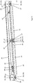
- Figure 1 shows a locking device 1 according to the invention in an exploded view.
- the locking device 1 is used to determine a building door, not shown, in a locked state of the locking device 1.
- a movement of the building door is released.
- the locking device 1 is designed to hold the building door in an open state and to enable the building door to be closed in the event of a fire.
- the locking device 1 is therefore suitable for locking a fire door.
- the locking device 1 comprises a slide 2.
- the slide 2 can be locked and released by a locking mechanism 3.
- the slide 2 is guided in a slide 4.
- the slider 2 can be connected to the building door, in particular to the fire door, via a lever (not shown).
- a control device 5 receives a signal from a fire alarm and then causes the locking mechanism 3 to release the slide 2.
- the locking device 1 comprises a housing 10.
- the housing 10 encloses the control device 5.
- the housing 10 accommodates the slide rail 4.
- the housing 10 comprises a rear side 11 which is used for fastening to a building door, in particular a door frame or a wall.
- the rear 11 is formed by a mounting plate 12.
- the rear side 11 can comprise a layer of intumescent material (not shown) which faces the wall or the building door.
- the layer of intumescent material can be attached to the mounting plate 12.
- the housing 10 comprises a panel 13.
- the panel 13 is arranged opposite the rear side 11.
- the panel 13 thus at least partially forms a front side of the housing 10.
- the housing 10 comprises an upper side 15.
- the upper side 15 faces a room ceiling in an assembled state of the door device 1.
- the housing 10 comprises an underside 16. In an assembled state of the door device 1, the underside 16 faces a room floor.
- the housing 10 may include an H-beam 14.
- the H-beam 14 can include the top 15 and the bottom 16.
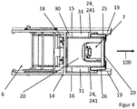
- An intermediate wall 18 of the H-beam 14 connects the upper side 15 to the lower side 16. Through the intermediate wall 18, the housing 10 provides a first receiving space 6 and a second receiving space 7, as in FIG Figure 4 shown.
- the second receiving space 7 is formed like a rail.
- the top 15 and the bottom 16 each include a projection 19 (see Fig. Figure 4 ).
- the housing can comprise side members 17.
- the hold-open device 1 comprises electrochemical energy stores 21.
- the electrochemical energy stores 21 serve to supply the door device 1, in particular the control device 5, with electrical power. In particular, the supply of electrical current can take place exclusively through the electrochemical energy store 21.
- the electrochemical energy stores 21 are designed as a battery or accumulator.
- the electrochemical energy stores 21 are accommodated in a holder 20.
- the holder 20 with the electrochemical energy stores 21 is accommodated in the housing 10.
- the locking device 1 comprises at least two storage groups 40, 50.
- the electrochemical energy storage devices 21 are divided into the storage groups 40, 50.
- Figure 5 FIG. 8 shows an exploded view of the storage groups 40, 50, to which reference is made below.
- each of the storage groups 40, 50 comprises several, e.g. B. two, energy storage devices 21.
- Each of the storage groups 40, 50 also includes an integration element 41, 51.
- the integration element 41, 51 ensures that only the prescribed electrochemical energy storage devices 21 can be used in the door device 1.
- a fitter is forced by the integration elements 41, 51 to use the entire storage groups 40, 50 provided when installing or replacing the electrochemical energy storage devices 21. This prevents the fitter from using only the electrochemical energy stores 21 without the connection elements 41, 51.
- the electrochemical energy stores 21 of a storage group 40, 50 are materially connected to the respective integration element 41, 51 of the same storage group 40, 50.
- the storage groups include electrical connections 42, 52.
- the electrical connections 42, 52 are designed as flags.
- the electrical connections 42, 52 are materially connected to the electrochemical energy store 21.
- the integration elements 41, 51 each comprise a circuit board 43, 53.
- the electrical connections 42, 52 are in particular fastened to the circuit boards 43, 53 in a materially bonded manner.
- the electrochemical energy stores 21 and the associated integration elements 41, 51 are each connected to one another in one piece.
- the electrochemical energy stores 21 are connected both mechanically and electrically to the respective circuit board 43, 53 via the connections 42, 52.
- each storage group 40, 50 comprises at least one electrical connection means 44, 54.
- the first storage group 40 comprises a plug 44 and the second storage group 50 a socket 54 as electrical connection means 44, 54.
- the electrical connection means 44, 54 are on the respective associated Board 43, 53 attached.
- the electrochemical energy stores 21 are designed as lithium-ion batteries or lithium-ion accumulators.
- the lithium content of the electrochemical energy stores 21 of each storage group 40, 50 is below 2 g.
- the storage groups 40, 50 can be stored and transported particularly safely.
- the integration elements 41, 51 each comprise further electrical connection means 45, 55.
- the electrical connection means 45 is used for connection to a connection board 60, via which the electrical energy stores 21 are electrically connected to the control device 5.
- the connection board 60 comprises a plug connector 61.
- the electrical connection means 45 is also available as a plug connector, e.g. B. as a socket.
- the circuit boards 43, 53 comprise electrical conductors in order to conduct the electrical current from the electrical connections 42, 52 to the electrical connection means 45, 54.
- the circuit boards comprise electrical conductors in order to conduct the electrical current from the electrical connections 44, 55 to the electrical connections 45, 54.
- An electrical conductor can also serve to conduct the electrical current from the electrical connections 42, 52 to the electrical connection means 45, 54 and from the electrical connections 44, 55 to the electrical connections 45, 54.
- the electrical connection means 55 is in the Figures 1 to 5 embodiment shown has no function. In principle, however, the electrical connection means 55 is suitable for electrically connecting a further storage group.
- the electrical connection means 55 makes it possible to design the two integration elements 41, 51 identically. This facilitates the manufacture, storage and installation of the storage groups 40, 50.
- Each integration element 41, 51 each comprise a holding element 46, 56.
- the holding element 46, 56 serves to hold the circuit board 43, 53.
- the electrical conductors of the circuit board 43, 53 are protected as a result.
- the holding element 46, 56 mechanically stabilizes the plate 43, 53.
- the holding element 46, 56 is connected to the board 43, 53 in a reversibly releasable manner, in particular clipped.
- the holding elements 46, 56 comprise connecting means 47, 57 by which the holding elements 46, 56 are mechanically connected to one another after being inserted into the locking device 1.
- the holding elements 46, 56 comprise further connecting means 48, 58 which can be used to connect to further holding elements.
- the further connecting means 48, 58 are in the in the Figures 1 to 5 embodiment shown has no function. In principle, however, the further connecting means 48, 58 are suitable for mechanically connecting a further storage group.
- the further connecting means 48, 58 make it possible to design the two holding elements 46, 56 identically. This facilitates the manufacture, storage and installation of the storage groups 40, 50.
- the two storage groups 40, 50 are particularly preferably designed identically.
- the holding element 46, 56 is spatially dimensioned in such a way that the holding element 46, 56 is clamped in the holder 20.
- the holding elements 46, 56 comprise side parts 70.
- the side parts 70 prevent the storage groups 40, 50 in the holder 20 from tipping over.
- the connection element 41, 51 comprises a connection element 49, 59 for mechanical fastening to the holder 20.
- the connection element 49, 59 is designed as an opening 49, 59.
- the opening 49, 59 is formed both in the board 43, 53 and in the holding element 46, 56, so that a mushroom head-shaped fastening piece 62, for. B. a screw (s. Figure 3 ) the opening 49, 59 can protrude.
- the connection element 41, 51 is fastened to the holder 20 by the fastening piece 62.
- the opening 49, 59 tapers.
- the mushroom-headed fastening piece 62 can already be fastened in the holder 20 before the storage groups 40, 50 are inserted.
- the wider part of the opening 49, 59 can receive the fastening piece 62.
- the storage group 40, 50 is fastened to the holder 20 by moving the storage group 40, 50 in the direction of the arrow 101 (see Fig. Figure 5 ) such that the fastening piece 62 is received in the tapered part of the opening 49, 59.
- the tapered part of the opening 49, 59 has smaller spatial dimensions than the mushroom head of the fastening piece 62, so that the storage group 40, 50 forms a form fit with the fastening piece 62.
- the storage groups 40, 50 can first be joined together and then inserted together into the housing 10.
- the storage groups 40, 50 can, however, also be inserted individually into the housing 10 and connected to one another in the housing 10.
- the storage groups 40, 50 are shifted into one another.
- the first storage group 40 is first inserted into the holder 20.
- the wider part of the opening 49 receives the corresponding fastening piece 62.
- the storage group 40 is then displaced in the direction of the arrow 101, so that the tapered part of the opening 49 forms a form fit with the fastening piece 62.
- an electrical connection between the connecting means 45 and the plug connector 61 is established at the same time.
- the second storage group 50 is then inserted into the holder 20.
- the wider part of the opening 59 receives the corresponding fastening piece 62.
- the storage group 50 is then shifted in the direction of the arrow 101, so that the tapered part of the opening 59 forms a form fit with the fastening piece 62.
- an electrical connection between the connection means 54 of the second storage group 50 and the connection means 44 of the first storage group 40 is established.
- a mechanical connection between the first and the second storage group 40, 50 is also established at the same time by the connection means 47, 57.
- the storage groups 40, 50 are inserted into the housing 10 at the same time, the storage groups 40, 50 are first connected to one another outside the housing 10 in such a way that an electrical connection of the connection means 54 of the second storage group 50 to the connection means 44 of the first storage group 40 and at the same time a mechanical connection of the first and the second storage group 40, 50 is established by the connecting means 47, 57.
- the storage groups 40, 50 are then inserted into the holder 20.
- the wider parts of the openings 49, 59 each receive the corresponding fastening piece 62.
- the storage group 40 is then shifted in the direction of the arrow 101, so that the tapered parts of the openings 49, 59 form a form fit with the respective fastening piece 62.
- an electrical connection between the connecting means 45 and the plug connector 61 is established at the same time.
- the holder 20 remains in the housing 10 during an exchange of the storage groups 40, 50.
- the fastening pieces 62 remain in the housing 10 during an exchange.
- the storage groups 40, 50 are removed from the housing 10 in the opposite direction to the insertion:
- the second storage group 50 is initially displaced against the direction of the arrow 101 so that the fastening piece 62 reaches the wider part of the opening 59.
- the electrical connection to the first storage group 40 is released in that the connection means 54 disengages from the connection means 44.
- the second storage group 50 can then be removed from the housing 10.
- the first storage group 40 can then initially be displaced against the direction of the arrow 101, so that the fastening piece 62 reaches the wider part of the opening 49. At the same time, the electrical connection to the connection board 60 is released in that the connection means 45 disengages from the plug connector 61. The first storage group 40 can then be taken out of the housing 10.
- the storage groups 40, 50 can in particular be removed from the housing together.
- the electrochemical energy stores 21 are spaced apart from the circuit board 43, 53 by the electrical connections 42, 52. This reduces the introduction of heat into the electrochemical energy store from a rear wall 22 of the holder.
- the integration element 41, 51 protrudes beyond the electrochemical energy storage device 21. In other words, the width b of the integration element 41, 51 is greater than the width of the electrochemical energy storage device 21. In this way, an input of heat into the electrochemical energy storage device 21 from the side walls 25, 26 of the holder 20 is avoided.
- the locking device 1 comprises a release device 30, which is in the Figures 2 and 3 is shown.
- the triggering device 30 is used to open the housing 10 at a triggering temperature.
- the opening of the housing 10 can prevent the electrochemical energy storage device 21 from heating up excessively.
- the release device 30 is formed from an intumescent material.
- the volume of the release device 30 increases suddenly, in particular by a multiple.
- the increase in volume can continue above the trigger temperature.
- the increase in volume of the intumescent material can be caused by evaporation, in particular of water. Because the release device 30 is made of intumescent material, the housing 10 is opened particularly reliably.
- the triggering device 30 opens the housing 10 in that the panel 13 is moved away from the rest of the housing in a direction of movement 100.
- the triggering device 30 opens the housing 10 by the triggering device 30 moving the holder 20 in the direction of movement 100, in particular shifting or pivoting it.
- the holder 20 in turn moves the screen 13.
- the triggering device 30 moves the holder 20 with the electrochemical energy stores 21 at least partially out of the housing 10 in the direction of movement 100 due to the volume increase.
- a movement out of the housing 10 is understood to mean a movement out of a space between the upper side 15 and the lower side 16.
- the holder 20 with the electrochemical energy stores 21 moves partially out of the second receiving space 7. In this way, excessive heating of the electrochemical energy stores 21 can be prevented particularly well.
- the holder 20 with the electrical energy stores 21 is located partially outside the space between the upper side 15 and the lower side 16 after the volume increase of the release element 30.
- the trigger device 30 is arranged between the holder 20 and the rear side 11.
- the release device 30 rests on the holder 20.
- the triggering device 30 is preferably connected to the holder 20, in particular glued. As a result, the holder 20 is held in the case of a partial movement of the holder 20 out of the housing 10. This prevents the holder 20 from falling down.
- the release device 30 can be designed in the form of a plate.
- the holder 20 has the rear wall 22.
- the rear wall 22 faces the rear side 11 of the housing 10.
- the triggering device 30 can rest against the rear wall 22, in particular be connected to the rear wall 22.
- the triggering device 30 covers the rear wall 22 with the exception of end regions 23 of the holder 20.
- the end regions 23 are formed in the form of a web in the region of the rear wall 22. As a result, the heat input via the end regions 23 is low.
- the holder 20 comprises elements 24.
- the elements 24 can serve at least partially as retaining elements 241.
- the retention element 241 serves to partially retain the holder 20 in the housing 10 when the volume of the release element 30 increases.
- the retaining elements 241 serve as a pivot axis.
- the retaining elements 241 serving as pivot axes are preferably in the area of the end regions 23 arranged.
- the retaining elements 241 serving as a pivot axis are located at an angle next to the release device 30.
- the holder 20 comprises the side walls 25, 26, in particular an upper side wall 25 and a lower side wall 26.
- the lower side wall 26 serves to be located outside the housing 10 between the electrochemical energy stores 21 and the floor of the room after the volume increase of the release element 30. In this way, heat can be kept away from the electrochemical energy stores 21.
- the side walls 25, 26 serve to guide the holder 20 during the movement of the holder 20 during the increase in volume of the release element 30.
- the upper side wall 25 rests against the top 15.
- the side walls 25, 26 are spaced apart from the upper or lower housing side 15, 16.
- the elements 24, which correspond to spacing elements 24, are used for this purpose.
- the spacing elements 24 hold the side walls 25, 26 apart from the upper or lower housing side 15, 16.
- the spacing elements 24 protrude from the side walls 25, 26.
- the spacing elements 24 are arranged in a half of the side walls 25, 26 that is remote from the rear side 11.
- Cooling elements 31 are arranged in the space between the side walls 25, 26 and the top or bottom 15, 16.
- the cooling elements 31 are designed as an intumescent material.
- the cooling elements 31 protect the electrochemical energy stores 21 from being heated by the cooling elements 31 effecting cooling above the intumenscence temperature.
- the holder 20 is fastened within the housing 10, in particular within the second receiving space 7, below the trigger temperature.
- the holder 20 comprises contact surfaces 27.
- the contact surfaces 27 bear against the projections 19.
- the elements 24 include the contact surfaces 27.
- the holder 20 is clamped in the housing 10.
- the door device 1 comprises a bracing means (not shown).
- the bracing means is z. B. designed as one or more screws.
- the bracing means is fastened in the holder 20.
- the bracing means is preferably fastened in the rear wall 22, in particular in the end regions 23.
- the end regions 23 can include bracing means receptacles 28 (see Sect. Figure 2 ).
- the tensioning means in particular a tip of the screw, rests against the partition 18.
- the bracing means and the contact surfaces 27 the holder 20 is braced in the housing 10, in particular in the second receiving space 7.
- the bracing means spaced the holder 20 from the intermediate wall 18. This reduces the heat input into the holder 20.
- the tensioning means thus also serves as a spacing means.
- the holder 20 Due to the positive fit of the contact surfaces 23 with the projections 19, the holder 20 is held in a positive fit in the direction of movement 100 below the triggering temperature.
- the contact surfaces 23 thus serve as form-fit means.
- the form fit of the contact surfaces 23 with the projections 19 is at least partially canceled.
- the elements 24 and thus the contact surfaces 23 break off from the rest of the holder 20.
- the elements 24, which are arranged in front of the triggering device 30 in the direction of movement 100 and are provided with the reference number 242 in the figures break off.
- the elements 24 which are not arranged in the end regions 23 and are provided with the reference number 242 in the figures thus break off.
- the elements 24 partially serve as retaining means 241 and part 242 of the elements 24 enable the break-off of the form fit and the opening of the housing 10. All elements 24 serve as spacing elements and all elements 24 include contact surfaces as form fit means.
- the holder 20 comprises fastening elements 29 for fastening the cover 13.
- the cover 13 is fastened magnetically to the fastening elements 29.
- the holder 20 is also designed in such a way that the panel 13 rests on the holder 20.
- the locking device 1 comprises fastening devices 9 to which the panel 13 is fastened.
- the fastening devices 9 are arranged outside the holder 20.
- the screen 13 is magnetically attached to the fastening devices 9.
- the diaphragm 13 is designed to be flexible.
- the screen 13 is made of plastic. As a result of the increase in volume, the screen 13 bends and thus enables the holder 20 to move out of the housing 10. Even after the volume has been increased, the panel 13 is at least partially fastened to at least one of the fastening elements 29 or fastening devices 9.
- the holder 20 is constructed in several parts. In particular, each part of the holder 20 receives a storage group 40, 50.
- the multi-part holder 20 makes it possible to pivot the parts of the holder individually when increasing the volume.
- the release device 30 in particular can be divided accordingly.
Landscapes
- Chemical & Material Sciences (AREA)
- Chemical Kinetics & Catalysis (AREA)
- Electrochemistry (AREA)
- General Chemical & Material Sciences (AREA)
- Engineering & Computer Science (AREA)
- Mechanical Engineering (AREA)
- Business, Economics & Management (AREA)
- Emergency Management (AREA)
- Battery Mounting, Suspending (AREA)
Description
- Die Erfindung betrifft eine Feststellvorrichtung, für eine Brandschutztür, mit einem Gehäuse und mit mehreren elektrochemischen Energiespeichern zur Energieversorgung der Türvorrichtung gemäß dem Oberbegriff des Patentanspruchs 1.
- Für den sicheren Betrieb einer batteriebetriebenen Türvorrichtung ist die Verwendung von vorgeschriebenen Batterien essentiell. So kann es sein, dass bei Einbau von unerwünschten Batterie die Türvorrichtung nicht oder nicht wie vorgesehen funktioniert. Insbesondere für Brandschutztüren muss der Einbau der korrekten Batterien gewährleistet sein. Türvorrichtungen für Brandschutztüren müssen einen Brandtest durchlaufen. Der Einbau von nicht getesteten Batterien kann zu einem unbekannten, nicht getesteten Verhalten im Brandfall führen. Ein Zusammensetzen der vorgeschriebenen Batterien zu einem einzigen Batteriepaket kann jedoch zu Problemen bei der Lagerung und dem Transport führen. Das Dokument
EP3064688A1 beschreibt eine Feststellvorrichtung des Stands der Technik. - Es ist die Aufgabe der Erfindung, eine Feststellvorrichtung, anzugeben, bei der auf einfache Art und Weise der Einbau der vorgeschriebenen elektrochemischen Energiespeicher gewährleistet ist, insbesondere ohne Probleme bei Lagerung und/oder Transport zu verursachen.
- Diese Aufgabe wird durch gemäß dem unabhängigen Anspruch 1 gelöst. Vorteilhafte Weiterbildungen sind in den abhängigen Vorrichtungsansprüchen, der Beschreibung und in den Figuren angegeben. Die Aufgabe der Erfindung wird auch durch eine Brandschutztür mit einer erfindungsgemäßen Feststellvorrichtung gelöst. Hierbei kann die erfindungsgemäße Feststellvorrichtung wie in den Ansprüchen oder in der Beschreibung angegeben ausgebildet sein.
- Die zuvor hergeleitete und aufgezeigte Aufgabe ist ausgehend von der eingangs beschriebenen Feststellvorrichtung dadurch gelöst, dass die Feststellvorrichtung zumindest zwei Speichergruppen umfasst, wobei jede Speichergruppe zumindest einen der elektrochemischen Energiespeicher und ein Einbindungselement zum Einbinden des zumindest einen elektrochemischen Energiespeichers in die übrige Feststellvorrichtung umfasst.
- Dadurch, dass zumindest zwei Speichergruppen vorgesehen sind und jede Speichergruppe neben dem eigentlichen elektrochemischen Energiespeicher noch ein Einbindungselement umfasst, ist es nicht möglich, nur die elektrochemischen Energiespeicher in die Feststellvorrichtung einzusetzen. Vielmehr wird ein Monteur oder derjenige, der eine Wartung der Feststellvorrichtung vornimmt, gezwungen, die Speichergruppen mit den elektrochemischen Energiespeichern in die Feststellvorrichtung einzusetzen. Das Einbindungselement dient zur Codierung der Speichergruppe bezüglich der Feststellvorrichtung.
- Das Einbindungselement dient insbesondere zur mechanischen und/oder elektrischen Codierung der Speichergruppe bezüglich der Feststellvorrichtung. Durch das Einbindungselement passt die Speichergruppe zu der übrigen Feststellvorrichtung.
- Insbesondere wird mittels des Einbindungselements die elektrochemischen Energiespeicher mechanisch und/oder elektrisch in die übrige Feststellvorrichtung eingefügt. Dadurch, dass zumindest zwei Speichergruppen vorhanden sind, ist gewährleistet, dass die Speichergruppen, ohne elektrisch miteinander verbunden zu sein, transportiert und/oder gelagert werden können. Hierdurch werden Problemen bei der Lagerung und/oder dem Transport vermieden.
- Die Speichergruppen sind insbesondere vor der Montage, z. B. bei einem Transport zu der zu wartenden Feststellvorrichtung, bei einem Transport der zu installierenden Feststellvorrichtung oder
- in einem Lager, elektrisch voneinander getrennt. Die Speichergruppen sind bevorzugt elektrisch miteinander verbindbar. Die elektrische Verbindung der Speichergruppen ist besonders bevorzugt reversibel lösbar.
- Besonders bevorzugt sind die Speichergruppen vor der Montage, z. B. bei einem Transport zu der zu wartenden Feststellvorrichtung, bei einem Transport der zu installierenden Feststellvorrichtung oder in einem Lager, mechanisch voneinander getrennt. Die Speichergruppen können somit separat voneinander ausgebildet sein. Die Speichergruppen sind bevorzugt mechanisch miteinander verbindbar. Die mechanische Verbindung der Speichergruppen ist besonders bevorzugt reversibel lösbar.
- Die Speichergruppen können in das Gehäuse einsetzbar sein. Im eingesetzten Zustand können die Speichergruppen elektrisch und/oder mechanisch miteinander verbunden sein. Im betriebsfertigen Zustand der Feststellvorrichtung sind bevorzugt die Speichergruppen in dem Gehäuse eingesetzt. Im betriebsfertigen Zustand der Feststellvorrichtung sind bevorzugt die Speichergruppen elektrisch miteinander verbunden.
- Es kann sein, dass jede Speichergruppe mehrere elektrochemische Energiespeicher umfasst. Wird im Folgenden die Speichergruppe mit dem elektrochemischen Energiespeicher beschrieben, so können stattdessen auch auf mehrere elektrochemische Energiespeicher gemeint sein.
- Die Feststellvorrichtung kann dazu ausgebildet sein, die Gebäudetür in einem offenen Zustand zu halten und im Brandfall ein Schließen der Gebäudetür freizugeben. Die Feststellvorrichtung kann somit zum Öffnen, Schließen und/oder Feststellen einer Gebäudetür ausgebildet sein.
- Die Feststellvorrichtung kann eine Steuerungsvorrichtung umfassen. Die Steuerungsvorrichtung kann zum Freigeben, Öffnen und/oder Schließen der Tür, insbesondere im Brandfall, dienen.
- Die Steuerungsvorrichtung kann in dem Gehäuse der Feststellvorrichtung aufgenommen sein. Ein Feststellmechanismus zum Feststellen der Gebäudetür kann in dem Gehäuse der Feststellvorrichtung aufgenommen sein.
- Das Gehäuse kann eine Rückseite umfassen. Die Rückseite ist dazu vorgesehen, an der Gebäudetür oder einer Wand befestigt zu werden.
- Die Rückseite des Gehäuses kann eine Montageplatte umfassen. Die Montageplatte kann reversibel lösbar mit dem übrigen Gehäuse verbunden sein.
- Insbesondere kann das Gehäuse eine Blende umfassen. Die Blende kann der Rückseite gegenüberliegend angeordnet sein. Somit kann die Blende zumindest teilweise eine Vorderseite des Gehäuses bilden.
- Vorzugsweise ist vorgesehen, dass der elektrochemischen Energiespeicher derart zu dem Einbindungselement angeordnet ist, dass eine Manipulation sichtbar ist. Hierdurch ist ein Ersetzen eines vorgeschriebenen elektrochemischen Energiespeichers durch einen anderen Energiespeicher sofort sichtbar.
- Der elektrochemische Energiespeicher kann mit dem jeweiligen Einbindungselement stoffschlüssig verbunden ist. Hierdurch kann der elektrochemische Energiespeicher nicht zerstörungsfrei von dem Einbindungselement lösbar sein. Hierdurch kann eine Manipulation sofort sichtbar sein. Das Einbindungselement kann mehrteilig ausgebildet sein. Die stoffschlüssige Verbindung kann zwischen einem Teil des Einbindungselements und des elektrochemischen Energiespeichers ausgebildet sein.
- Es ist denkbar, dass das Einbindungselement elektrische Anschlüsse zum elektrischen Anschließen des elektrochemischen Energiespeichers umfasst. Beispielsweise kann das Einbindungselement elektrisch leitende Fahnen umfassen. Durch den elektrischen Anschluss kann zugleich der elektrochemische Energiespeicher mechanisch an dem Einbindungselement befestigt sein. Bevorzugt ist der elektrochemische Energiespeicher stoffschlüssig elektrisch leitend mit zumindest einem der elektrischen Anschlüssen, bevorzugt mit den elektrischen Anschlüssen, verbunden. Beispielsweise kann die stoffschlüssige elektrisch leitende Verbindung als ein Verschweißen oder als ein Verlöten realisiert sein. Z. B. kann der elektrochemische Energiespeicher mit zumindest einer Fahne verschweißt oder verlötet sein.
- Es ist denkbar, dass mittels der elektrischen Anschlüsse, insbesondere der Fahnen, der elektrochemische Energiespeicher von dem übrigen Einbindungselement beabstandet ist. Hierdurch wird eine Wärmeübertragung von dem Einbindungselement auf den elektrochemischen Energiespeicher verringert.
- Vorzugsweise ist vorgesehen, dass die Speichergruppen in dem Gehäuse elektrisch miteinander verbunden sind. Die Speichergruppen können elektrische Anschlussmittel zum elektrischen Verbinden der Speichergruppen untereinander umfassen. Bevorzugt sind die elektrischen Anschlussmittel reversibel lösbar. Die Anschlussmittel sind insbesondere als Steckverbinder ausgestaltet.
- Bevorzugt können die Einbindungselemente die elektrische Anschlussmittel zum elektrischen Verbinden der Speichergruppen untereinander umfassen. Zusätzlich oder alternativ kann zumindest eine Speichergruppe, insbesondere zumindest ein Einbindungselement, ein elektrisches Anschlussmittel zum elektrischen Verbinden an einen Energieverbraucher der Feststellvorrichtung umfassen. Das elektrische Anschlussmittel zum elektrischen Verbinden an einen Energieverbraucher kann als ein Steckverbinder, d. h. als ein Stecker oder als eine Buchse, ausgebildet sein.
- Bei dem Energieverbraucher der Feststellvorrichtung kann es sich insbesondere um eine Steuerungsvorrichtung handeln. Der Anschluss an den Energieverbraucher kann mittelbar ausgebildet sein. Beispielsweise kann der Energieverbraucher, z. B. die Steuerungsvorrichtung, über eine Anschlussplatine mit dem Anschlussmittel elektrisch verbunden sein.
- Es kann sein, dass die Speichergruppe, insbesondere das Einbindungselement, derart in das Gehäuse einsetzbar ist, dass zugleich mit einem mechanischen Befestigungsschritt ein elektrisches Anschließen des zumindest einen elektrochemischen Energiespeichers erfolgt. Insbesondere kann ein Anschlussmittel zeitgleich mit dem mechanischen Befestigungsschritt elektrisch kontaktiert werden. Bei dem Anschlussmittel kann es sich um ein Anschlussmittel zum elektrischen Verbinden mit einer weiteren Speichergruppe oder um ein Anschlussmittel zur elektrischen Verbindung mit einem Energieverbraucher handeln. Als Befestigungsschritt kann eine Bewegung des Einbindungselements zur mechanischen Befestigung des Einbindungselements in dem Gehäuse angesehen werden. Beispielsweise kann bei der mechanischen Befestigung des Einbindungselements in dem Gehäuse zugleich eine Steckverbindung der Steckverbinder hergestellt werden. Zur mechanische Befestigung kann die Speichergruppe, insbesondere das Einbindungselement, z. B. unter einem Vorsprung geschoben werden. Der Vorsprung kann insbesondere als ein Kopf eines pilzkopfförmigen Befestigungsstücks, z. B. als ein Schraubenkopf, ausgebildet sein.
- Insbesondere kann vorgesehen sein, dass das Einbindungselement eine Platine umfasst. Die Einbindungselemente können jeweils eine Platine umfassen. Insbesondere kann der elektrochemische Energiespeicher zumindest mittelbar auf der Platine befestigt, insbesondere stoffschlüssig und/oder elektrisch leitend befestigt, sein. Beispielsweise können die Anschlüsse, insbesondere die Fahnen, an der Platine befestigt sein. Die Anschlüsse, insbesondere die Fahnen, können insbesondere stoffschlüssig und/oder elektrisch leitend an der Platine befestigt sein. Z. B. können die Fahnen an der Platine festgelötet oder verschweißt sein.
- Die Platine kann elektrische Leiter zum elektrischen Verbinden des elektrochemischen Energiespeichers mit dem Anschlussmittel des Einbindungselements umfassen. Das zumindest eine Anschlussmittel kann auf der Platine befestigt, insbesondere stoffschlüssig und/oder elektrisch leitend befestigt, sein. Zumindest eine Platine kann elektrische Leiter zum elektrischen Verbinden zweier Anschlussmittel umfassen.
- Vorzugsweise ist vorgesehen, dass das Einbindungselement ein Halteelement zur Halterung der Platine und/oder zum Schutz der elektrischen Leiter der Platine umfasst. Die Einbindungselemente können jeweils ein Halteelement umfassen. Insbesondere können das Halteelement und die Platine reversibel lösbar miteinander mechanisch verbunden sein. Die reversibel lösbare Verbindung kann ein Form- und/oder Kraftschluss sein. Beispielsweise sind das Halteelement und die Platine miteinander verklipst.
- Es ist denkbar, dass die Einbindungselemente, insbesondere die Halteelemente, Verbindungsmittel zum mechanischen Verbinden der Einbindungselemente untereinander umfassen. Hierdurch kann die mechanische Stabilität der Speichergruppen erhöht werden. Durch die Verbindungsmittel können die Einbindungselemente reversibel lösbar miteinander verbunden sein. Die Verbindungsmittel können z. B. als ein Vorsprung und eine Aufnahme ausgebildet sein. Der Vorsprung eines Einbindungselements kann z. B. in die korrespondierende Aufnahme eines weiteren Einbindungselements zur mechanischen Verbindung eingreifen.
- Zusätzlich oder alternativ kann das Einbindungselement, insbesondere das Halteelement und/oder die Platine, ein Verbindungselement zum Verbinden mit einem weiteren Element der Türvorrichtung umfassen. Bevorzugt dient das Verbindungselement zur zumindest mittelbaren mechanischen Verbindung der Speichergruppe mit dem Gehäuse. Die mechanische Verbindung kann reversibel lösbar sein. Die mechanische Verbindung kann als ein Form- und/oder Kraftschluss ausgebildet sein. Das Verbindungselement kann z. B. als Öffnung oder Ausnehmung ausgebildet sein. Die Öffnung oder Ausnehmung kann z. B. zur Aufnahme des Vorsprungs, bevorzugt des pilzkopfförmigen Befestigungsstücks, besonders bevorzugt der Schraube, dienen.
- Die Speichergruppen können identisch ausgebildet sein. Die Platinen mehrerer Speichergruppen können identisch zueinander ausgebildet sein. Die Halteelemente mehrerer Speichergruppen können identisch zueinander ausgebildet sein. Die Anschlussmittel mehrere Speichergruppen können identisch zueinander ausgebildet sein. Hierdurch ist die Herstellung, die Lagerung und die Montage der Speichergruppen vereinfacht. Es ist denkbar, dass durch die identische Ausbildung Anschlussmittel einer Speichergruppe in dem eingebauten Zustand ungenutzt bleibt. Es ist denkbar, dass durch die identische Ausbildung zumindest ein Verbindungsmittel einer Speichergruppe in dem eingebauten Zustand ungenutzt bleibt.
- Erfindungsgemäß ist vorgesehen, dass der gesamte Lithiumgehalt der elektrochemischen Energiespeicher jeder Speichergruppe unter 2 g liegt. Hierdurch ist eine besonders sichere Lagerung der Speichergruppen und/oder ein besonders sicherer Transport zur Feststellvorrichtung möglich.
- Bevorzugt kann es sein, dass die Speichergruppen einzeln in das Gehäuse einsetzbar sind. Hierdurch kann die Montage oder die Wartung erheblich erleichert werden. Die Speichergruppen können reversibel lösbar in das Gehäuse einsetzbar sein. Es kann es sein, dass die Speichergruppen einzeln in das Gehäuse herausnehmbar sind.
- Insbesondere kann die Blende der Feststellvorrichtung abnehmbar ausgebildet sein. Bevorzugt ist vorgesehen, dass nach Abnehmen der Blende die Speichergruppen in das Gehäuse einsetzbar sind.
- Es ist denkbar, dass die Feststellvorrichtung eine Halterung zur Aufnahme der Speichergruppen umfasst. Das Verbindungselement kann z. B. zur mechanischen Verbindung mit der Halterung dienen.
- Das Einbindungselement ist bevorzugt derart ausgebildet, dass das Einbindungselement den elektrochemischen Energiespeicher von der übrigen Feststellvorrichtung beabstandet.
- Insbesondere kann das Einbindungselement den elektrochemischen Energiespeicher von zumindest einer Seitenwand der Halterung und/oder dem Gehäuse, insbesondere einer Ober-und/oder Unterseite des Gehäuses, beabstanden. Hierdurch kann eine Wärmeübertragung von der Feststellvorrichtung, insbesondere von der Halterung, auf den elektrochemischen Energiespeicher verringert werden.
- Das Einbindungselement kann in einer Draufsicht den elektrochemischen Energiespeicher in zumindest einer, bevorzugt zumindest zwei Raumrichtungen, überragen. So kann eine Breite des Einbindungselements größer sein als eine Breite des elektrochemischen Energiespeichers. Hierdurch kann das Einbindungselement den elektrochemischen Energiespeicher vor einer zu großen Wärmeübertragung schützen.
- Es ist denkbar, dass das Einbindungselement, insbesondere das Halteelement, zumindest ein Seitenteil, bevorzugt mehrere Seitenteile, umfasst. Durch die Seitenteile kann ein Kippschutz erreicht werden. Hierdurch wird ein Kippen der Speichergruppen und damit ein erhöhter Wärmeeintrag in die elektrochemischen Energiespeicher vermieden.
- Es ist denkbar, dass die Speichergruppen, insbesondere zusammen mit der Halterung, im Brandfall von der Rückseite des Gehäuses wegbewegbar sind. Hierzu kann eine Auslösevorrichtung der Feststellvorrichtung dienen. Es ist denkbar, dass die Speichergruppen, insbesondere zusammen mit der Halterung, im Brandfall aus dem Gehäuse bewegbar sind. Hierzu kann die Auslösevorrichtung dienen. Besonders bevorzugt können die Speichergruppen hierzu insbesondere zueinander verschwenken. Insbesondere können sich die Speichergruppen hierbei voneinander lösen.
- Es kann vorgesehen sein, dass zwischen der Rückseite der Feststellvorrichtung und den Speichergruppen, insbesondere zwischen der Rückseite der Feststellvorrichtung und der
- Halterung, ein Brandschutzmaterial angeordnet ist. Das Brandschutzmaterial kann als ein intumeszierendes Material ausgebildet sein. Durch das Brandschutzmaterial können im Brandfall die Speichergruppen von der Rückseite wegbewegbar sein.
- Die erfindungsgemäße Feststellvorrichtung ist für eine Verwendung bei einer Brandschutztür vorgesehen. Durch die erfindungsgemäße Feststellvorrichtung ist die Verwendung der korrekten elektrochemischen Energiespeicher sichergestellt. Hierdurch ist ein verlässlicher Brandschutz gegeben.
- Die Erfindung wird nachfolgend anhand von einem Ausführungsbeispiel näher erläutert. Technische Merkmale mit gleicher Funktion sind in den Figuren mit identischen Bezugszeichen versehen. Es zeigen:
- Fig. 1
- eine erfindungsgemäße Feststellvorrichtung in einer Explosionsdarstellung,
- Fig. 2
- eine Halterung und eine Auslösevorrichtung der erfindungsgemäßen Feststellvorrichtung der
Figur 1 , - Fig. 3
- die Halterung und die Auslösevorrichtung aus
Figur 2 in einer weiteren Perspektive, - Fig. 4
- eine Seitenansicht von Teilen erfindungsgemäßen Feststellvorrichtung aus
Figur 1 , wobei insbesondere Seitenelemente, eine Blende und eine Montageplatte fehlen, - Figur 5
- Speichergruppen der erfindungsgemäßen Feststellvorrichtung aus
Figur 1 in einer Explosionsdarstellung. -
Figur 1 zeigt eine erfindungsgemäße Feststellvorrichtung 1 in einer Explosionsdarstellung. Die Feststellvorrichtung 1 dient dazu, in einem festgestellten Zustand der Feststellvorrichtung 1 eine nicht dargestellte Gebäudetür festzustellen. In einem freigebenden Zustand der Feststellvorrichtung 1 ist eine Bewegung der Gebäudetür freigegeben. Insbesondere ist die Feststellvorrichtung 1 dazu ausgebildet, die Gebäudetür in einem offenen Zustand zu halten und im Brandfall ein Schließen der Gebäudetür freizugeben. Somit ist die Feststellvorrichtung 1 zum Feststellen einer Brandschutztür geeignet. - Die Feststellvorrichtung 1 umfasst ein Gleitstück 2. Das Gleitstück 2 ist durch einen Feststellmechanismus 3 feststell- und freigebbar. Das Gleitstück 2 ist in einer Gleitschiene 4 geführt. Das Gleitstück 2 ist über einen nicht dargestellten Hebel mit der Gebäudetür, insbesondere mit der Brandschutztür, verbindbar. Eine Steuerungsvorrichtung 5 empfängt ein Signal eines Brandmelders und veranlasst daraufhin den Feststellmechanismus 3, das Gleitstück 2 freizugeben.
- Die Feststellvorrichtung 1 umfasst ein Gehäuse 10. Das Gehäuse 10 umschließt die Steuerungsvorrichtung 5. Das Gehäuse 10 nimmt die Gleitschiene 4 auf.
- Das Gehäuse 10 umfasst eine Rückseite 11, die zur Befestigung an einer Gebäudetür, insbesondere einem Türrahmen oder einer Wand, dient. Die Rückseite 11 wird durch eine Montageplatte 12 gebildet. Die Rückseite 11 kann eine Schicht aus intumeszierenden Material (nicht dargestellt) umfassen, die der Wand oder der Gebäudetür zugewandt ist. Die Schicht aus intumenszierenden Material kann an der Montageplatte 12 befestigt sein.
- Das Gehäuse 10 umfasst eine Blende 13. Die Blende 13 ist der Rückseite 11 gegenüberliegend angeordnet. Somit bildet die Blende 13 zumindest teilweise eine Vorderseite des Gehäuses 10.
- Das Gehäuse 10 umfasst eine Oberseite 15. Die Oberseite 15 ist in einem montierten Zustand der Türvorrichtung 1 einer Raumdecke zugewandt. Das Gehäuse 10 umfasst eine Unterseite 16. Die Unterseite 16 ist in einem montierten Zustand der Türvorrichtung 1 einem Raumboden zugewandt.
- Das Gehäuse 10 kann einen H-Träger 14 umfassen. Der H-Träger 14 kann die Oberseite 15 und die Unterseite 16 umfassen. Eine Zwischenwand 18 des H-Trägers 14 verbindet die Oberseite 15 mit der Unterseite 16. Durch die Zwischenwand 18 stellt das Gehäuse 10 einen ersten Aufnahmeraum 6 und einen zweiten Aufnahmeraum 7 zur Verfügung, wie in
Figur 4 dargestellt. - Der zweite Aufnahmeraum 7 ist schienenartig ausgebildet. Hierzu umfassen die Oberseite 15 und die Unterseite 16 jeweils einen Vorsprung 19 (s.
Figur 4 ). - Das Gehäuse kann Seitenelemente 17 umfassen.
- Die Feststellvorrichtung 1 umfasst elektrochemische Energiespeicher 21. Die elektrochemischen Energiespeicher 21 dienen zur Versorgung der Türvorrichtung 1, insbesondere der Steuerungsvorrichtung 5, mit elektrischem Strom. Hierbei kann insbesondere die Versorgung mit elektrischen Strom ausschließlich durch die elektrochemischen Energiespeicher 21 erfolgen. Die elektrochemischen Energiespeicher 21 sind als Batterie oder Akkumulator ausgebildet. Die elektrochemischen Energiespeicher 21 sind in einer Halterung 20 aufgenommen. Die Halterung 20 mit den elektrochemischen Energiespeichern 21 ist in dem Gehäuse 10 aufgenommen.
- Die Feststellvorrichtung 1 umfasst zumindest zwei Speichergruppen 40, 50. Die elektrochemischen Energiespeicher 21 sind in die Speichergruppen 40, 50 aufgeteilt.
Figur 5 zeigt eine Explosionsdarstellung der Speichergruppen 40, 50, auf die im Folgenden Bezug genommen wird. Beispielhaft umfasst jede der Speichergruppen 40, 50 mehrere, z. B. zwei, Energiespeicher 21. Jede der Speichergruppen 40, 50 umfasst zudem ein Einbindungselement 41, 51. Durch das Einbindungselement 41, 51 wird gewährleistet, dass nur die vorgeschriebenen elektrochemischen Energiespeicher 21 in die Türvorrichtung 1 eingesetzt werden können. Ein Monteur wird durch die Einbindungselemente 41, 51 gezwungen, die vorgesehenen gesamten Speichergruppen 40, 50 bei einer Installation oder einem Auswechseln der elektrochemischen Energiespeicher 21 einzusetzen. Hierdurch ist es dem Monteur verwehrt, nur die elektrochemischen Energiespeicher 21 ohne die Einbindungselemente 41, 51 einzusetzen. - Die elektrochemischen Energiespeicher 21 einer Speichergruppe 40, 50 sind mit dem jeweiligen Einbindungselement 41, 51 derselben Speichergruppe 40, 50 stoffschlüssig verbunden. Hierzu umfassen die Speichergruppen elektrische Anschlüsse 42, 52. Die elektrischen Anschlüsse 42, 52 sind als Fahnen ausgebildet. Die elektrischen Anschlüsse 42, 52 sind mit den elektrochemischen Energiespeicher 21 stoffschlüssig verbunden.
- Die Einbindungselemente 41, 51 umfassen jeweils eine Platine 43, 53. Die elektrischen Anschlüsse 42, 52 sind insbesondere stoffschlüssig auf den Platinen 43, 53 befestigt. Somit sind die elektrochemischen Energiespeicher 21 und die dazugehörigen Einbindungselemente 41, 51 jeweils einstückig miteinander verbunden. Über die Anschlüsse 42, 52 sind die elektrochemischen Energiespeicher 21 sowohl mechanisch als auch elektrisch mit der jeweiligen Platine 43, 53 verbunden.
- Während einem Transport und/oder während einer Lagerung der Speichergruppen 40, 50 sind die Speichergruppen 40, 50 elektrisch voneinander getrennt. In der Feststellvorrichtung 1 sind die Speichergruppen 40, 50 hingegen elektrisch miteinander verbunden. Hierzu umfasst jede Speichergruppe 40, 50 zumindest ein elektrisches Anschlussmittel 44, 54. Z. B. umfasst die erste Speichergruppe 40 einen Stecker 44 und die zweite Speichergruppe 50 eine Buchse 54 als elektrisches Anschlussmittel 44, 54. Die elektrischen Anschlussmittel 44, 54 sind auf der jeweilig dazugehörigen Platine 43, 53 befestigt.
- Die elektrochemischen Energiespeicher 21 sind als Lithium-Ionen Batterien oder Lithium-Ionen Akkumulatoren ausgebildet. Insbesondere liegt der Lithium-Gehalt der elektrochemischen Energiespeicher 21 einer jeden Speichergruppe 40, 50 unterhalb von 2 g. Hierdurch sind die Speichergruppen 40, 50 besonders sicher zu lagern und zu transportieren.
- Die Einbindungselemente 41, 51 umfassen jeweils weitere elektrische Anschlussmittel 45, 55. Das elektrische Anschlussmittel 45 dient zum Anschluss an eine Anschlussplatine 60, über die die elektrischen Energiespeicher 21 mit der Steuerungsvorrichtung 5 elektrisch verbunden sind. Die Anschlussplatine 60 umfasst hierzu einen Steckverbinder 61. Ebenfalls ist das elektrische Anschlussmittel 45 als ein Steckverbinder, z. B. als eine Buchse, ausgebildet. Die Platinen 43, 53 umfassen elektrische Leiter, um den elektrischen Strom von den elektrischen Anschlüssen 42, 52 zu den elektrischen Anschlussmitteln 45, 54 zu leiten. Ferner umfassen die Platinen elektrische Leiter, um den elektrischen Strom von den elektrischen Anschlüssen 44, 55 zu den elektrischen Anschlüssen 45, 54 zu leiten. Ein elektrischer Leiter kann zugleich dazu dienen, um den elektrischen Strom von den elektrischen Anschlüssen 42, 52 zu den elektrischen Anschlussmitteln 45, 54 und von den elektrischen Anschlüssen 44, 55 zu den elektrischen Anschlüssen 45, 54 zu leiten.
- Das elektrische Anschlussmittel 55 ist in dem in den
Figuren 1 bis 5 gezeigten Ausführungsbeispiel funktionslos. Prinzipiell ist das elektrische Anschlussmittel 55 aber geeignet, eine weitere Speichergruppe elektrisch anzuschließen. Durch das elektrische Anschlussmittel 55 ist es möglich, die beiden Einbindungselemente 41, 51 identisch auszubilden. Dieses erleichtert die Herstellung, die Lagerung und den Einbau der Speichergruppen 40, 50. - Jedes Einbindungselement 41, 51 umfassen jeweils ein Halteelement 46, 56. Das Halteelement 46, 56 dient zur Aufnahme der Platine 43, 53. Hierdurch werden die elektrischen Leiter der Platine 43, 53 geschützt. Zudem stabilisiert das Halteelement 46, 56 die Platine 43, 53 mechanisch. Das Halteelement 46, 56 ist mit der Platine 43, 53 reversibel lösbar verbunden, insbesondere verclipst.
- Die Halteelemente 46, 56 umfassen Verbindungsmittel 47, 57, durch die die Halteelemente 46, 56 mechanisch nach einem Einsetzen in die Feststellvorrichtung 1 miteinander verbunden sind. Die Halteelemente 46, 56 umfassen weitere Verbindungsmittel 48, 58, die zur Verbindung mit weiteren Halteelementen dienen können. Die weiteren Verbindungsmittel 48, 58 sind in dem in den
Figuren 1 bis 5 gezeigten Ausführungsbeispiel funktionslos. Prinzipiell sind die weiteren Verbindungsmittel 48, 58 aber geeignet, eine weitere Speichergruppe mechanisch anzubinden. Durch die weiteren Verbindungsmittel 48, 58 ist es möglich, die beiden Halteelemente 46, 56 identisch auszubilden. Dieses erleichtert die Herstellung, die Lagerung und den Einbau der Speichergruppen 40, 50. Besonders bevorzugt sind die beiden Speichergruppen 40, 50 identisch ausgebildet. - Das Halteelement 46, 56 ist derart räumlich dimensioniert, dass das Halteelement 46, 56 sich in der Halterung 20 verklemmt.
- Die Halteelemente 46, 56 umfassen Seitenteile 70. Die Seitenteile 70 verhindern die ein Kippen der Speichergruppen 40, 50 in der Halterung 20.
- Das Einbindungselement 41, 51 umfasst ein Verbindungselement 49, 59 zum mechanischen Befestigen an der Halterung 20. Das Verbindungselement 49, 59 ist als eine Öffnung 49, 59 ausgebildet. Die Öffnung 49, 59 ist sowohl in der Platine 43, 53 als auch in dem Halteelement 46, 56 ausgebildet, so dass ein pilzkopfförmiges Befestigungsstück 62, z. B. eine Schraube (s.
Figur 3 ) die Öffnung 49, 59 durchragen kann. Durch das Befestigungsstück 62 ist das Einbindungselement 41, 51 an der Halterung 20 befestigt. - Die Öffnung 49, 59 verjüngt sich. Das pilzköpfige Befestigungsstück 62 kann bereits vor dem Einsetzen der Speichergruppen 40, 50 in der Halterung 20 befestigt sein. Bei dem Einsetzen der Speichergruppe 40, 50 kann der breitere Teil der Öffnung 49, 59 das Befestigungsstück 62 aufnehmen. Die Befestigung der Speichergruppe 40, 50 mit der Halterung 20 erfolgt durch ein Verschieben der Speichergruppe 40, 50 gemäß der Pfeilrichtung 101 (s.
Figur 5 ) derart, dass das Befestigungsstück 62 in dem verjüngten Teil der Öffnung 49, 59 aufgenommen wird. Der verjüngte Teil der Öffnung 49, 59 weist geringere räumliche Ausmaße als der Pilzkopf des Befestigungsstück 62 auf, so dass die Speichergruppe 40, 50 einen Formschluss mit dem Befestigungsstück 62 eingeht. - Durch das Verschieben der Speichergruppe 40, 50 unter das Befestigungsstück 62 wird zugleich eine elektrische Verbindung hergestellt.
- Die Speichergruppen 40, 50 können zunächst zusammengefügt und danach gemeinsam in das Gehäuse 10 eingesetzt werden. Die Speichergruppen 40, 50 können aber auch einzeln in das Gehäuse 10 eingesetzt werden und im Gehäuse 10 miteinander verbunden werden. Zum elektrischen und mechanischen Verbinden der Speichergruppen 40, 50 untereinander innerhalb des Gehäuses 10 oder außerhalb des Gehäuses 10, werden die Speichergruppen 40, 50 ineinander verschoben.
- Werden die Speichergruppen 40, 50 nacheinander in das Gehäuse 10 eingesetzt, so wird zunächst die erste Speichergruppe 40 in die Halterung 20 eingefügt. Hierbei nimmt der breitere Teil der Öffnung 49 das entsprechende Befestigungsstück 62 auf. Dann wird die Speichergruppe 40 gemäß der Pfeilrichtung 101 verschoben, so dass der verjüngte Teil der Öffnung 49 einen Formschluss mit dem Befestigungsstück 62 eingeht. Durch die Verschiebung in Pfeilrichtung 101 wird zugleich eine elektrische Verbindung des Anschlussmittels 45 mit dem Steckverbinder 61 hergestellt. Danach wird die zweite Speichergruppe 50 in die Halterung 20 eingefügt. Hierbei nimmt der breitere Teil der Öffnung 59 das entsprechende Befestigungsstück 62 auf. Dann wird die Speichergruppe 50 gemäß der Pfeilrichtung 101 verschoben, so dass der verjüngte Teil der Öffnung 59 einen Formschluss mit dem Befestigungsstück 62 eingeht. Zugleich wird eine elektrische Verbindung des Anschlussmittels 54 der zweiten Speichergruppe 50 mit dem Anschlussmittel 44 der ersten Speichergruppe 40 hergestellt. Ebenfalls wird zugleich eine mechanische Verbindung der ersten und der zweiten Speichergruppe 40, 50 durch die Verbindungsmittel 47, 57 hergestellt.
- Werden die Speichergruppen 40, 50 zeitgleich in das Gehäuse 10 eingesetzt, so werden zunächst außerhalb des Gehäuses 10 die Speichergruppen 40, 50 miteinander derart verbunden, so dass eine elektrische Verbindung des Anschlussmittels 54 der zweiten Speichergruppe 50 mit dem Anschlussmittel 44 der ersten Speichergruppe 40 und zugleich eine mechanische Verbindung der ersten und der zweiten Speichergruppe 40, 50 durch die Verbindungsmittel 47, 57 hergestellt ist. Danach werden die Speichergruppen 40, 50 in die Halterung 20 eingefügt. Hierbei nehmen die breiteren Teile der Öffnungen 49, 59 jeweils das entsprechende Befestigungsstück 62 auf. Dann werden die Speichergruppe 40 gemäß der Pfeilrichtung 101 verschoben, so dass die verjüngten Teile der Öffnungen 49, 59 einen Formschluss mit dem jeweiligen Befestigungsstück 62 eingehen. Durch die Verschiebung in Pfeilrichtung 101 wird zugleich eine elektrische Verbindung des Anschlussmittels 45 mit dem Steckverbinder 61 hergestellt.
- Die Halterung 20 verbleibt während eines Auswechselns der Speichergruppen 40, 50 in dem Gehäuse 10. Insbesondere verbleiben die Befestigungsstücke 62 während eines Auswechselns in dem Gehäuse 10.
- Um die entladenen elektrochemischen Energiespeicher 21 auszuwechseln, ist es demnach ausreichend, die Blende 13 von dem übrigen Gehäuse 10 zu entfernen und nach dem Entfernen der Speichergruppen mit den entladenen elektrochemischen Energiespeichern 21 einen der beschriebenen Handlungsabläufe durchzuführen. Das Entfernen der Speichergruppen 40, 50 aus dem Gehäuse 10 erfolgt entgegengesetzt dem Einsetzen: Hierbei wird die zweite Speichergruppe 50 zunächst entgegen der Pfeilrichtung 101 verschoben, so dass das Befestigungsstück 62 in den breiteren Teil der Öffnung 59 gelangt. Zugleich wird die elektrische Verbindung zu der ersten Speichergruppe 40 gelöst, indem das Anschlussmittel 54 außer Eingriff mit dem Anschlussmittel 44 gelangt. Dann kann die zweite Speichergruppe 50 aus dem Gehäuse 10 genommen werden. Anschließend kann die erste Speichergruppe 40 zunächst entgegen der Pfeilrichtung 101 verschoben, so dass das Befestigungsstück 62 in den breiteren Teil der Öffnung 49 gelangt. Zugleich wird die elektrische Verbindung zu der Anschlussplatine 60 gelöst, indem das Anschlussmittel 45 außer Eingriff mit dem Steckverbinder 61 gelangt. Dann kann die erste Speichergruppe 40 aus dem Gehäuse 10 genommen werden.
- Alternativ ist es möglich, die Speichergruppen 40, 50 gemeinsam entgegen der Pfeilrichtung 101 zu verschieben, wodurch die mechanische Befestigung durch die Befestigungsstücke 62 und die elektrische Verbindung mit dem Steckverbinder 61 gelöst wird. Danach können die Speichergruppen 40, 50 insbesondere gemeinsam aus dem Gehäuse entnommen werden. Die elektrochemischen Energiespeicher 21 sind durch die elektrischen Anschlüsse 42, 52 von der Platine 43, 53 beabstandet. Hierdurch wird ein Wärmeeintrag in die elektrochemischen Energiespeicher von einer Rückwand 22 der Halterung verringert. Das Einbindungselement 41, 51 überragt in einer Draufsicht die elektrochemischen Energiespeicher 21. Anders ausgedrückt ist die Breite b der Einbindungselemente 41, 51 größer als die Breite der elektrochemischen Energiespeicher 21. Somit sind die elektrochemischen Energiespeicher 21 von Seitenwänden 25, 26 der Halterung 20 beabstandet. Hierdurch wird ein Wärmeeintrag in die elektrochemischen Energiespeicher 21 von der Seitenwänden 25, 26 der Halterung 20 vermieden.
- Die Feststellvorrichtung 1 umfasst eine Auslösevorrichtung 30, die in den
Figuren 2 und3 dargestellt ist. Die Auslösevorrichtung 30 dient dazu, bei einer Auslösetemperatur das Gehäuse 10 zu öffnen. Durch die Öffnung des Gehäuses 10 kann eine zu starke Erwärmung der elektrochemischen Energiespeicher 21 verhindert werden. Hierdurch kann auch bei der Auslösetemperatur die Sicherheit der Feststellvorrichtung 1 gewährleistet sein. Die Auslösevorrichtung 30 ist aus intumeszierendem Material ausgebildet. Bei der Auslösetemperatur vergrößert sich das Volumen der Auslösevorrichtung 30 sprunghaft, insbesondere um ein Vielfaches. Die Volumenvergrößerung kann oberhalb der Auslösetemperatur weitergeführt sein. Die Volumenvergrößerung des intumeszierenden Materials kann durch eine Verdampfung insbesondere von Wasser verursacht sein. Dadurch, dass die Auslösevorrichtung 30 aus intumeszierendem Material ist, wird das Gehäuse 10 besonders zuverlässig geöffnet. - Die Auslösevorrichtung 30 öffnet das Gehäuse 10, indem die Blende 13 gemäß einer Bewegungsrichtung 100 von dem übrigen Gehäuse wegbewegt wird. Die Auslösevorrichtung 30 öffnet das Gehäuse 10, indem die Auslösevorrichtung 30 die Halterung 20 in Bewegungsrichtung 100 bewegt, insbesondere verschiebt oder verschwenkt. Die Halterung 20 wiederrum bewegt die Blende 13.
- Die Auslösevorrichtung 30 bewegt die Halterung 20 mit den elektrochemischen Energiespeichern 21 durch die Volumenvergrößerung zumindest teilweise aus dem Gehäuse 10 gemäß der Bewegungsrichtung 100 heraus. Unter einer Bewegung aus dem Gehäuse 10 wird eine Bewegung aus einem Zwischenraum zwischen Oberseite 15 und Unterseite 16 heraus verstanden. Insbesondere bewegt sich die Halterung 20 mit den elektrochemischen Energiespeichern 21 teilweise aus dem zweiten Aufnahmeraum 7 heraus. Hierdurch kann besonders gut eine starke Erwärmung der elektrochemischen Energiespeicher 21 verhindert werden. Die Halterung 20 mit den elektrischen Energiespeichern 21 befindet sich nach der Volumenvergrößerung des Auslöseelements 30 teilweise außerhalb des Raumes zwischen Oberseite 15 und Unterseite 16.
- Die Auslösevorrichtung 30 ist zwischen der Halterung 20 und der Rückseite 11 angeordnet. Die Auslösevorrichtung 30 liegt an der Halterung 20 an. Bevorzugt ist die Auslösevorrichtung 30 mit der Halterung 20 verbunden, insbesondere verklebt. Hierdurch wird die Halterung 20 bei einer teilweisen Bewegung der Halterung 20 aus dem Gehäuse 10 gehalten. Hierdurch wird ein Herunterfallen der Halterung 20 verhindert.
- Die Auslösevorrichtung 30 kann plattenartig ausgebildet sein. Die Halterung 20 weist die Rückwand 22 auf. Die Rückwand 22 weist zur Rückseite 11 des Gehäuses 10. Die Auslösevorrichtung 30 kann an der Rückwand 22 anliegen, insbesondere mit der Rückwand 22 verbunden sein. Wie in
Figur 2 gezeigt, bedeckt die Auslösevorrichtung 30 die Rückwand 22 mit Ausnahme von Endbereichen 23 der Halterung 20. Die Endbereiche 23 sind im Bereich der Rückwand 22 stegförmig ausgebildet. Hierdurch ist der Wärmeeintrag über die Endbereiche 23 gering. - Die Halterung 20 umfasst Elemente 24. Die Elemente 24 können zumindest teilweise als Rückhalteelemente 241 dienen. Die Rückhalteelemente 241 dient dazu, die Halterung 20 teilweise bei der Volumenvergrößerung des Auslöseelements 30 in dem Gehäuse 10 zurückzuhalten. Hierbei dienen die Rückhalteelemente 241 als Schwenkachse. Hierdurch kann die Halterung 20 vor einem Herunterfallen bewahrt werden. Die als Schwenkachse dienenden Rückhalteelemente 241 sind bevorzugt im Bereich der Endbereiche 23 angeordnet. Somit befinden sich die als Schwenkachse dienenden Rückhalteelemente 241 schräg neben der Auslösevorrichtung 30.
- Die Halterung 20 umfasst die Seitenwände 25, 26, insbesondere eine obere Seitenwand 25 und eine untere Seitenwand 26.
- Die untere Seitenwand 26 dient dazu, nach der Volumenvergrößerung des Auslöseelements 30 außerhalb des Gehäuses 10 zwischen den elektrochemischen Energiespeichern 21 und dem Raumboden sich zu befinden. Hierdurch kann Wärme von den elektrochemischen Energiespeichern 21 abgehalten werden.
- Die Seitenwände 25, 26 dienen zur Führung der Halterung 20 bei der Bewegung der Halterung 20 während der Volumenvergrößerung des Auslöseelements 30. Hierzu liegt die obere Seitenwand 25 an der Oberseite 15 an. Unterhalb der Auslösetemperatur sind die Seitenwände 25, 26 beabstandet von der oberen- bzw- unteren Gehäuseseite 15, 16. Hierzu dienen die Elemente 24, die Beabstandungselementen 24 entsprechen. Die Beabstandungselemente 24 beanstanden die Seitenwände 25, 26 von der oberen- bzwunteren Gehäuseseite 15, 16. Hierzu ragen die Beabstandungselemente 24 von den Seitenwänden 25, 26 ab. Die Beabstandungselemente 24 sind in einer zur Rückseite 11 entfernten Hälfte der Seitenwände 25, 26 angeordnet.
- In dem Zwischenraum zwischen den Seitenwänden 25, 26 und der Ober- bzw. Unterseite 15, 16 sind Kühlelemente 31 angeordnet. Die Kühlelemente 31 sind als intumeszierendem Material ausgebildet. Die Kühlelemente 31 schützen die elektrochemischen Energiespeicher 21 vor einer Erwärmung, indem die Kühlelemente 31 oberhalb der Intumenszenztemperatur eine Kühlung bewirken.
- Die Halterung 20 ist unterhalb der Auslösetemperatur innerhalb des Gehäuses 10, insbesondere innerhalb des zweiten Aufnahmeraums 7, befestigt. Die Halterung 20 umfasst Anlageflächen 27. Die Anlageflächen 27 liegen an den Vorsprüngen 19 an. Die Elemente 24 umfassen die Anlageflächen 27.
- Die Halterung 20 ist in dem Gehäuse 10 verspannt. Hierzu umfasst die Türvorrichtung 1 ein nicht dargestelltes Verspannungsmittel. Das Verspannungsmittel ist z. B. als eine oder mehrere Schraube ausgebildet. Das Verspannungsmittel ist in der Halterung 20 befestigt. Das Verspannungsmittel ist bevorzugt in der Rückwand 22, insbesondere in den Endbereichen 23, befestigt. Hierzu können die Endbereiche 23 Verspannungsmittelaufnahmen 28 umfassen (s.
Figur 2 ). - Das Verspannungsmittel, insbesondere eine Spitze der Schraube, liegt an der Zwischenwand 18 an. Somit wird durch das Verspannungsmittel und die Anlageflächen 27 die Halterung 20 in dem Gehäuse 10, insbesondere in dem zweiten Aufnahmeraum 7, verspannt.
- Das Verspannungsmittel beabstandet die Halterung 20 von der Zwischenwand 18. Hierdurch wird der Wärmeeintrag in die Halterung 20 verringert. Somit dient das Verspannungsmittel zugleich als ein Beabstandungsmittel.
- Durch den Formschluss der Anlageflächen 23 mit den Vorsprüngen 19 ist die Halterung 20 in der Bewegungsrichtung 100 unterhalb der Auslösetemperatur formschlüssig gehalten. Die Anlageflächen 23 dienen somit als Formschlussmittel. Bei einer Volumenvergrößerung wird der Formschluss der Anlageflächen 23 mit den Vorsprüngen 19 zumindest teilweise aufgehoben. Durch die Volumenvergrößerung bricht zumindest ein Teil der Elemente 24 und damit der Anlageflächen 23 von der übrigen Halterung 20 ab. Insbesondere brechen die Elemente 24, die in Bewegungsrichtung 100 vor der Auslösevorrichtung 30 angeordnet sind und in den Figuren mit dem Bezugszeichen 242 versehen sind, ab. Somit brechen die Elemente 24, die nicht in den Endbereichen 23 angeordnet sind und in den Figuren mit dem Bezugszeichen 242 versehen sind, ab.
- Somit dienen die Elemente 24 teilweise als Rückhaltemittel 241 und ein Teil 242 der Elemente 24 ermöglichen durch ein Abbrechen die Aufhebung des Formschluss und die Öffnung des Gehäuses 10. Alle Elemente 24 dienen als Beabstandungselemente und alle Elemente 24 umfassen Anlageflächen als Formschlussmittel.
- Die Halterung 20 umfasst Befestigungselemente 29 zum Befestigen der Blende 13. Die Blende 13 ist magnetisch an den Befestigungselementen 29 befestigt. Die Halterung 20 ist des Weiteren derart ausgebildet, dass die Blende 13 auf der Halterung 20 aufliegt.
- Die Feststellvorrichtung 1 umfasst Befestigungsvorrichtungen 9, an denen die Blende 13 befestigt ist. Die Befestigungsvorrichtungen 9 sind außerhalb der Halterung 20 angeordnet. Die Blende 13 ist magnetisch an den Befestigungsvorrichtungen 9 befestigt.
- Die Blende 13 ist biegsam ausgebildet. Die Blende 13 ist aus Kunststoff gefertigt. Durch die Volumenvergrößerung biegt sich die Blende 13 und ermöglicht somit eine Bewegung der Halterung 20 aus dem Gehäuse 10 heraus. Auch nach der Volumenvergrößerung ist die Blende 13 zumindest teilweise an zumindest einem der Befestigungselementen 29 oder Befestigungsvorrichtungen 9 befestigt.
- Die Halterung 20 ist mehrteilig ausgebildet. Insbesondere nimmt jedes Teil der Halterung 20 eine Speichergruppe 40, 50 auf. Durch die mehrteilige Halterung 20 ist es möglich, die Teile der Halterung bei der Volumenvergrößerung einzeln zu verschwenken. Hierzu kann insbesondere die Auslösevorrichtung 30 entsprechend geteilt sein.
Claims (15)
- Feststellvorrichtung für eine Brandschutztür,mit einem Gehäuse (10) undmit mehreren elektrochemischen Energiespeichern (21) zur Energieversorgung der Feststellvorrichtung (1),dadurch gekennzeichnet, dassdie Feststellvorrichtung (1) zumindest zwei Speichergruppen (40, 50) umfasst, wobei jede Speichergruppe (40, 50) zumindest einen der elektrochemischen Energiespeicher (21) und ein Einbindungselement (41, 51) zum Einbinden des zumindest einen elektrochemischen Energiespeichers (21) in die übrige Feststellvorrichtung (1) umfasst,wobei der gesamte Lithiumgehalt der elektrochemischen Energiespeicher (21) jeder Speichergruppe (40, 50) unter 2 g liegt.
- Feststellvorrichtung (1) nach Anspruch 1, dadurch gekennzeichnet, dass der elektrochemische Energiespeicher (21) mit dem jeweiligen Einbindungselement (41, 51) stoffschlüssig verbunden ist.
- Feststellvorrichtung (1) nach Anspruch 1 oder 2, dadurch gekennzeichnet, dass das Einbindungselement (41, 51) elektrische Anschlüsse (43, 53) zum elektrischen Anschließen des elektrochemischen Energiespeichers (21) umfasst, wobei insbesondere durch den elektrischen Anschluss zugleich der elektrochemische Energiespeicher (21) mechanisch, insbesondere stoffschlüssig, an dem Einbindungselement (41, 51) befestigt ist.
- Feststellvorrichtung (1) nach einem der vorhergehenden Ansprüche, dadurch gekennzeichnet, dass die Speichergruppen (40, 50) in dem Gehäuse (10) elektrisch miteinander verbunden sind, wobei die Speichergruppen (40, 50), insbesondere die Einbindungselemente (41, 51), elektrische, reversibel lösbare Anschlussmittel (44, 54, 55) zum elektrischen Verbinden der Speichergruppen untereinander umfassen.
- Feststellvorrichtung (1) nach einem der vorhergehenden Ansprüche, dadurch gekennzeichnet, dass das Einbindungselement (41, 51) elektrische Anschlussmittel (44, 54, 45, 55) zum Anschließen an einen Energieverbraucher der Feststellvorrichtung (1), insbesondere einer Steuerungsvorrichtung (5), umfasst.
- Feststellvorrichtung (1) nach einem der vorhergehenden Ansprüche, dadurch gekennzeichnet, dass das Einbindungselement (41, 51) derart in das Gehäuse (10) einsetzbar ist, dass zugleich mit einem mechanischen Befestigungsschritt ein elektrisches Anschließen des elektrochemischen Energiespeichers (21) erfolgt, insbesondere, dass ein Anschlussmittel (44, 54, 45, 55) zeitgleich mit dem mechanischen Befestigungsschritt elektrisch kontaktiert wird.
- Feststellvorrichtung (1) nach einem der vorhergehenden Ansprüche, dadurch gekennzeichnet, dass das Einbindungselement (41, 51) eine Platine (43, 53) umfasst, wobei insbesondere der elektrochemische Energiespeicher (21) zumindest mittelbar auf der Platine (43, 53) befestigt, insbesondere festgelötet oder verschweißt, ist.
- Feststellvorrichtung (1) nach einem der vorhergehenden Ansprüche, dadurch gekennzeichnet, dass das Einbindungselement (41, 51) ein Halteelement (46, 56) zur Halterung der Platine (43, 53) und/oder zum Schutz der elektrischen Leiter der Platine (43, 53) umfasst, wobei insbesondere das Halteelement (46, 56) und die Platine (43, 53) reversibel lösbar miteinander verbunden ist.
- Feststellvorrichtung (1) nach einem der vorhergehenden Ansprüche, dadurch gekennzeichnet, dass das Einbindungselement (41, 51) ein Verbindungsmittel (47, 57) zum mechanischen Verbinden mit einem weiteren Einbindungselement (41, 51) umfasst und/oder das Einbindungselement (41, 51) ein Verbindungselement (49, 59) zum mechanischen Verbinden mit einem weiteren Element (20) der Feststellvorrichtung (1), umfasst.
- Feststellvorrichtung (1) nach einem der vorhergehenden Ansprüche, dadurch gekennzeichnet, dass mehrere Speichergruppen (40, 50) identisch zueinander ausgebildet sind.
- Feststellvorrichtung (1) nach einem der vorhergehenden Ansprüche, dadurch gekennzeichnet, dass jede Speichergruppe (40, 50) mehrere elektrochemische Energiespeicher (21) umfasst.
- Feststellvorrichtung (1) nach einem der vorhergehenden Ansprüche, dadurch gekennzeichnet, dass die Speichergruppen (40, 50) einzeln reversibel lösbar in das Gehäuse (10) einsetzbar sind, wobei insbesondere die Feststellvorrichtung (1) eine abnehmbare Blende (13) umfasst und nach Abnehmen der Blende (13) die Speichergruppen (40, 50) in das Gehäuse (10) einsetzbar sind.
- Feststellvorrichtung (1) nach einem der vorhergehenden Ansprüche, dadurch gekennzeichnet, dass die Feststellvorrichtung (1) eine Halterung (20) zur Aufnahme der Speichergruppen (40, 50) umfasst, insbesondere, dass das Einbindungselement (41, 51) derart ausgebildet ist, dass das Einbindungselement (41, 51) den elektrochemischen Energiespeicher (21) von zumindest einer Seitenwand (25, 26) der Halterung (20) beabstandet.
- Feststellvorrichtung (1) nach einem der vorhergehenden Ansprüche, dadurch gekennzeichnet, dass die Feststellvorrichtung (1) eine Rückseite (11) zur Befestigung an eine Wand oder eine Tür umfasst, wobei zwischen der Rückseite (11) der Feststellvorrichtung (1) und den Speichergruppen (40, 50), insbesondere zwischen der Rückseite (11) der Feststellvorrichtung (1) und der Halterung (20), ein Brandschutzmaterial (30) angeordnet ist, insbesondere, dass das Brandschutzmaterial (30) als ein intumeszierendes Material ausgebildet ist, wobei durch das Brandschutzmaterial (30) im Brandfall die Speichergruppen (40, 50) von der Rückseite (11) wegbewegbar sind.
- Brandschutztür mit einer Feststellvorrichtung (1) nach einem der vorhergehenden Ansprüche.
Priority Applications (1)
| Application Number | Priority Date | Filing Date | Title |
|---|---|---|---|
| EP17180067.5A EP3425146B1 (de) | 2017-07-06 | 2017-07-06 | Feststellvorrichtung für eine brandschutztür |
Applications Claiming Priority (1)
| Application Number | Priority Date | Filing Date | Title |
|---|---|---|---|
| EP17180067.5A EP3425146B1 (de) | 2017-07-06 | 2017-07-06 | Feststellvorrichtung für eine brandschutztür |
Publications (2)
| Publication Number | Publication Date |
|---|---|
| EP3425146A1 EP3425146A1 (de) | 2019-01-09 |
| EP3425146B1 true EP3425146B1 (de) | 2021-09-01 |
Family
ID=59295096
Family Applications (1)
| Application Number | Title | Priority Date | Filing Date |
|---|---|---|---|
| EP17180067.5A Active EP3425146B1 (de) | 2017-07-06 | 2017-07-06 | Feststellvorrichtung für eine brandschutztür |
Country Status (1)
| Country | Link |
|---|---|
| EP (1) | EP3425146B1 (de) |
Family Cites Families (2)
| Publication number | Priority date | Publication date | Assignee | Title |
|---|---|---|---|---|
| US20040219422A1 (en) * | 2003-05-01 | 2004-11-04 | Hauck Eric W. | Modular battery pack |
| DE102015102922A1 (de) * | 2015-03-02 | 2016-09-08 | Dorma Deutschland Gmbh | Feststellanordnung für eine Tür |
-
2017
- 2017-07-06 EP EP17180067.5A patent/EP3425146B1/de active Active
Also Published As
| Publication number | Publication date |
|---|---|
| EP3425146A1 (de) | 2019-01-09 |
Similar Documents
| Publication | Publication Date | Title |
|---|---|---|
| EP1927147B1 (de) | Akkupack sowie elektrohandwerkzeuggerät | |
| DE102004034396B4 (de) | Verbindungsteil und Verbindungsstecker für einen Kabelbaum | |
| DE102016105241B4 (de) | Fahrradbatteriehalterung und Fahrradbatterieeinheit | |
| EP2732486B1 (de) | Energiespeichermodul und befestigungsanordnung mit dem energiespeichermodul | |
| EP3743961B1 (de) | Baukastensystem zum herstellen eines elektrischen geräts und klemmeneinrichtung | |
| DE2451331A1 (de) | Speisequelle mit batteriehalter | |
| EP0167122B1 (de) | Tragbares elektromedizinisches Gerät | |
| EP2810342B1 (de) | Elektrisches kupplungselement | |
| EP4016716B1 (de) | Montagevorrichtung für eine verbundbatterie | |
| DE112014002529T5 (de) | Elektronische Steuereinheit und Schutzgehäuse | |
| EP2102954B1 (de) | Steckgehäusemodul | |
| EP2250706A2 (de) | Leiterplattenanordnung und elektrisches anschlussmodul | |
| DE102014205724A1 (de) | Energiespeichervorrichtung | |
| DE19807555C1 (de) | Aufbausystem zum Einschub von elektrischen Flachbaugruppen | |
| DE102019208769A1 (de) | Akkumulator | |
| DE102017103194B4 (de) | Akkupack | |
| WO2009033865A1 (de) | Zweimoduliges ladegerät | |
| DE102008043946A1 (de) | Sicherungseinrichtung für eine Akkumulatorzelle | |
| DE102019103772B4 (de) | Schutzleiteranschluss | |
| DE102010047458A1 (de) | Anschlussklemme | |
| EP3425150B1 (de) | Türvorrichtung | |
| EP3890102B1 (de) | Vorrichtung mit einem rahmen, der aufnahmen für die stirnseitigen endabschnitte von bezüglich ihrer längsachse parallel ausgerichteten batteriezellen aufweist | |
| DE3121883C1 (de) | Batteriegehäuse | |
| EP3978344A1 (de) | Fahrradrahmenrohr | |
| DE29519209U1 (de) | Batteriefach zur Aufnahme von Batteriezellen |
Legal Events
| Date | Code | Title | Description |
|---|---|---|---|
| PUAI | Public reference made under article 153(3) epc to a published international application that has entered the european phase |
Free format text: ORIGINAL CODE: 0009012 |
|
| STAA | Information on the status of an ep patent application or granted ep patent |
Free format text: STATUS: THE APPLICATION HAS BEEN PUBLISHED |
|
| AK | Designated contracting states |
Kind code of ref document: A1 Designated state(s): AL AT BE BG CH CY CZ DE DK EE ES FI FR GB GR HR HU IE IS IT LI LT LU LV MC MK MT NL NO PL PT RO RS SE SI SK SM TR |
|
| AX | Request for extension of the european patent |
Extension state: BA ME |
|
| STAA | Information on the status of an ep patent application or granted ep patent |
Free format text: STATUS: REQUEST FOR EXAMINATION WAS MADE |
|
| 17P | Request for examination filed |
Effective date: 20190709 |
|
| RBV | Designated contracting states (corrected) |
Designated state(s): AL AT BE BG CH CY CZ DE DK EE ES FI FR GB GR HR HU IE IS IT LI LT LU LV MC MK MT NL NO PL PT RO RS SE SI SK SM TR |
|
| STAA | Information on the status of an ep patent application or granted ep patent |
Free format text: STATUS: EXAMINATION IS IN PROGRESS |
|
| 17Q | First examination report despatched |
Effective date: 20200511 |
|
| REG | Reference to a national code |
Ref country code: DE Ref legal event code: R079 Ref document number: 502017011345 Country of ref document: DE Free format text: PREVIOUS MAIN CLASS: E05C0017280000 Ipc: E05F0015600000 |
|
| GRAP | Despatch of communication of intention to grant a patent |
Free format text: ORIGINAL CODE: EPIDOSNIGR1 |
|
| STAA | Information on the status of an ep patent application or granted ep patent |
Free format text: STATUS: GRANT OF PATENT IS INTENDED |
|
| RIC1 | Information provided on ipc code assigned before grant |
Ipc: H01M 50/502 20210101ALI20210201BHEP Ipc: E05B 47/00 20060101ALI20210201BHEP Ipc: E05F 15/60 20150101AFI20210201BHEP Ipc: H01M 50/213 20210101ALI20210201BHEP Ipc: E05C 17/28 20060101ALI20210201BHEP |
|
| INTG | Intention to grant announced |
Effective date: 20210305 |
|
| GRAS | Grant fee paid |
Free format text: ORIGINAL CODE: EPIDOSNIGR3 |
|
| GRAA | (expected) grant |
Free format text: ORIGINAL CODE: 0009210 |
|
| STAA | Information on the status of an ep patent application or granted ep patent |
Free format text: STATUS: THE PATENT HAS BEEN GRANTED |
|
| AK | Designated contracting states |
Kind code of ref document: B1 Designated state(s): AL AT BE BG CH CY CZ DE DK EE ES FI FR GB GR HR HU IE IS IT LI LT LU LV MC MK MT NL NO PL PT RO RS SE SI SK SM TR |
|
| REG | Reference to a national code |
Ref country code: GB Ref legal event code: FG4D Free format text: NOT ENGLISH |
|
| REG | Reference to a national code |
Ref country code: CH Ref legal event code: EP Ref country code: AT Ref legal event code: REF Ref document number: 1426434 Country of ref document: AT Kind code of ref document: T Effective date: 20210915 |
|
| REG | Reference to a national code |
Ref country code: DE Ref legal event code: R096 Ref document number: 502017011345 Country of ref document: DE |
|
| REG | Reference to a national code |
Ref country code: IE Ref legal event code: FG4D Free format text: LANGUAGE OF EP DOCUMENT: GERMAN |
|
| REG | Reference to a national code |
Ref country code: SE Ref legal event code: TRGR |
|
| REG | Reference to a national code |
Ref country code: NL Ref legal event code: FP |
|
| REG | Reference to a national code |
Ref country code: LT Ref legal event code: MG9D |
|
| PG25 | Lapsed in a contracting state [announced via postgrant information from national office to epo] |
Ref country code: RS Free format text: LAPSE BECAUSE OF FAILURE TO SUBMIT A TRANSLATION OF THE DESCRIPTION OR TO PAY THE FEE WITHIN THE PRESCRIBED TIME-LIMIT Effective date: 20210901 Ref country code: NO Free format text: LAPSE BECAUSE OF FAILURE TO SUBMIT A TRANSLATION OF THE DESCRIPTION OR TO PAY THE FEE WITHIN THE PRESCRIBED TIME-LIMIT Effective date: 20211201 Ref country code: HR Free format text: LAPSE BECAUSE OF FAILURE TO SUBMIT A TRANSLATION OF THE DESCRIPTION OR TO PAY THE FEE WITHIN THE PRESCRIBED TIME-LIMIT Effective date: 20210901 Ref country code: ES Free format text: LAPSE BECAUSE OF FAILURE TO SUBMIT A TRANSLATION OF THE DESCRIPTION OR TO PAY THE FEE WITHIN THE PRESCRIBED TIME-LIMIT Effective date: 20210901 Ref country code: FI Free format text: LAPSE BECAUSE OF FAILURE TO SUBMIT A TRANSLATION OF THE DESCRIPTION OR TO PAY THE FEE WITHIN THE PRESCRIBED TIME-LIMIT Effective date: 20210901 Ref country code: LT Free format text: LAPSE BECAUSE OF FAILURE TO SUBMIT A TRANSLATION OF THE DESCRIPTION OR TO PAY THE FEE WITHIN THE PRESCRIBED TIME-LIMIT Effective date: 20210901 Ref country code: BG Free format text: LAPSE BECAUSE OF FAILURE TO SUBMIT A TRANSLATION OF THE DESCRIPTION OR TO PAY THE FEE WITHIN THE PRESCRIBED TIME-LIMIT Effective date: 20211201 |
|
| PG25 | Lapsed in a contracting state [announced via postgrant information from national office to epo] |
Ref country code: PL Free format text: LAPSE BECAUSE OF FAILURE TO SUBMIT A TRANSLATION OF THE DESCRIPTION OR TO PAY THE FEE WITHIN THE PRESCRIBED TIME-LIMIT Effective date: 20210901 Ref country code: LV Free format text: LAPSE BECAUSE OF FAILURE TO SUBMIT A TRANSLATION OF THE DESCRIPTION OR TO PAY THE FEE WITHIN THE PRESCRIBED TIME-LIMIT Effective date: 20210901 Ref country code: GR Free format text: LAPSE BECAUSE OF FAILURE TO SUBMIT A TRANSLATION OF THE DESCRIPTION OR TO PAY THE FEE WITHIN THE PRESCRIBED TIME-LIMIT Effective date: 20211202 |
|
| PG25 | Lapsed in a contracting state [announced via postgrant information from national office to epo] |
Ref country code: IS Free format text: LAPSE BECAUSE OF FAILURE TO SUBMIT A TRANSLATION OF THE DESCRIPTION OR TO PAY THE FEE WITHIN THE PRESCRIBED TIME-LIMIT Effective date: 20220101 Ref country code: SM Free format text: LAPSE BECAUSE OF FAILURE TO SUBMIT A TRANSLATION OF THE DESCRIPTION OR TO PAY THE FEE WITHIN THE PRESCRIBED TIME-LIMIT Effective date: 20210901 Ref country code: SK Free format text: LAPSE BECAUSE OF FAILURE TO SUBMIT A TRANSLATION OF THE DESCRIPTION OR TO PAY THE FEE WITHIN THE PRESCRIBED TIME-LIMIT Effective date: 20210901 Ref country code: RO Free format text: LAPSE BECAUSE OF FAILURE TO SUBMIT A TRANSLATION OF THE DESCRIPTION OR TO PAY THE FEE WITHIN THE PRESCRIBED TIME-LIMIT Effective date: 20210901 Ref country code: PT Free format text: LAPSE BECAUSE OF FAILURE TO SUBMIT A TRANSLATION OF THE DESCRIPTION OR TO PAY THE FEE WITHIN THE PRESCRIBED TIME-LIMIT Effective date: 20220103 Ref country code: EE Free format text: LAPSE BECAUSE OF FAILURE TO SUBMIT A TRANSLATION OF THE DESCRIPTION OR TO PAY THE FEE WITHIN THE PRESCRIBED TIME-LIMIT Effective date: 20210901 Ref country code: CZ Free format text: LAPSE BECAUSE OF FAILURE TO SUBMIT A TRANSLATION OF THE DESCRIPTION OR TO PAY THE FEE WITHIN THE PRESCRIBED TIME-LIMIT Effective date: 20210901 Ref country code: AL Free format text: LAPSE BECAUSE OF FAILURE TO SUBMIT A TRANSLATION OF THE DESCRIPTION OR TO PAY THE FEE WITHIN THE PRESCRIBED TIME-LIMIT Effective date: 20210901 |
|
| REG | Reference to a national code |
Ref country code: DE Ref legal event code: R097 Ref document number: 502017011345 Country of ref document: DE |
|
| PLBE | No opposition filed within time limit |
Free format text: ORIGINAL CODE: 0009261 |
|
| STAA | Information on the status of an ep patent application or granted ep patent |
Free format text: STATUS: NO OPPOSITION FILED WITHIN TIME LIMIT |
|
| PG25 | Lapsed in a contracting state [announced via postgrant information from national office to epo] |
Ref country code: IT Free format text: LAPSE BECAUSE OF FAILURE TO SUBMIT A TRANSLATION OF THE DESCRIPTION OR TO PAY THE FEE WITHIN THE PRESCRIBED TIME-LIMIT Effective date: 20210901 Ref country code: DK Free format text: LAPSE BECAUSE OF FAILURE TO SUBMIT A TRANSLATION OF THE DESCRIPTION OR TO PAY THE FEE WITHIN THE PRESCRIBED TIME-LIMIT Effective date: 20210901 |
|
| 26N | No opposition filed |
Effective date: 20220602 |
|
| PG25 | Lapsed in a contracting state [announced via postgrant information from national office to epo] |
Ref country code: SI Free format text: LAPSE BECAUSE OF FAILURE TO SUBMIT A TRANSLATION OF THE DESCRIPTION OR TO PAY THE FEE WITHIN THE PRESCRIBED TIME-LIMIT Effective date: 20210901 |
|
| PG25 | Lapsed in a contracting state [announced via postgrant information from national office to epo] |
Ref country code: MC Free format text: LAPSE BECAUSE OF FAILURE TO SUBMIT A TRANSLATION OF THE DESCRIPTION OR TO PAY THE FEE WITHIN THE PRESCRIBED TIME-LIMIT Effective date: 20210901 |
|
| PG25 | Lapsed in a contracting state [announced via postgrant information from national office to epo] |
Ref country code: LU Free format text: LAPSE BECAUSE OF NON-PAYMENT OF DUE FEES Effective date: 20220706 |
|
| PG25 | Lapsed in a contracting state [announced via postgrant information from national office to epo] |
Ref country code: IE Free format text: LAPSE BECAUSE OF NON-PAYMENT OF DUE FEES Effective date: 20220706 |
|
| PG25 | Lapsed in a contracting state [announced via postgrant information from national office to epo] |
Ref country code: HU Free format text: LAPSE BECAUSE OF FAILURE TO SUBMIT A TRANSLATION OF THE DESCRIPTION OR TO PAY THE FEE WITHIN THE PRESCRIBED TIME-LIMIT; INVALID AB INITIO Effective date: 20170706 |
|
| PG25 | Lapsed in a contracting state [announced via postgrant information from national office to epo] |
Ref country code: MK Free format text: LAPSE BECAUSE OF FAILURE TO SUBMIT A TRANSLATION OF THE DESCRIPTION OR TO PAY THE FEE WITHIN THE PRESCRIBED TIME-LIMIT Effective date: 20210901 Ref country code: CY Free format text: LAPSE BECAUSE OF FAILURE TO SUBMIT A TRANSLATION OF THE DESCRIPTION OR TO PAY THE FEE WITHIN THE PRESCRIBED TIME-LIMIT Effective date: 20210901 |
|
| PG25 | Lapsed in a contracting state [announced via postgrant information from national office to epo] |
Ref country code: MT Free format text: LAPSE BECAUSE OF FAILURE TO SUBMIT A TRANSLATION OF THE DESCRIPTION OR TO PAY THE FEE WITHIN THE PRESCRIBED TIME-LIMIT Effective date: 20210901 |
|
| PGFP | Annual fee paid to national office [announced via postgrant information from national office to epo] |
Ref country code: NL Payment date: 20250721 Year of fee payment: 9 |
|
| PGFP | Annual fee paid to national office [announced via postgrant information from national office to epo] |
Ref country code: DE Payment date: 20250722 Year of fee payment: 9 |
|
| PGFP | Annual fee paid to national office [announced via postgrant information from national office to epo] |
Ref country code: BE Payment date: 20250721 Year of fee payment: 9 Ref country code: GB Payment date: 20250722 Year of fee payment: 9 |
|
| PGFP | Annual fee paid to national office [announced via postgrant information from national office to epo] |
Ref country code: AT Payment date: 20250722 Year of fee payment: 9 Ref country code: FR Payment date: 20250725 Year of fee payment: 9 |
|
| PGFP | Annual fee paid to national office [announced via postgrant information from national office to epo] |
Ref country code: SE Payment date: 20250722 Year of fee payment: 9 Ref country code: CH Payment date: 20250801 Year of fee payment: 9 |
|
| PG25 | Lapsed in a contracting state [announced via postgrant information from national office to epo] |
Ref country code: TR Free format text: LAPSE BECAUSE OF FAILURE TO SUBMIT A TRANSLATION OF THE DESCRIPTION OR TO PAY THE FEE WITHIN THE PRESCRIBED TIME-LIMIT Effective date: 20210901 |