EP3424863A1 - Multiple leaders for load bearing member sway reduction - Google Patents
Multiple leaders for load bearing member sway reduction Download PDFInfo
- Publication number
- EP3424863A1 EP3424863A1 EP18180199.4A EP18180199A EP3424863A1 EP 3424863 A1 EP3424863 A1 EP 3424863A1 EP 18180199 A EP18180199 A EP 18180199A EP 3424863 A1 EP3424863 A1 EP 3424863A1
- Authority
- EP
- European Patent Office
- Prior art keywords
- leader
- load bearing
- bearing member
- hoistway
- members
- Prior art date
- Legal status (The legal status is an assumption and is not a legal conclusion. Google has not performed a legal analysis and makes no representation as to the accuracy of the status listed.)
- Withdrawn
Links
- 230000002452 interceptive effect Effects 0.000 claims abstract description 5
- 230000002265 prevention Effects 0.000 claims abstract description 3
- 239000000463 material Substances 0.000 description 2
- 239000000725 suspension Substances 0.000 description 2
- 229910000831 Steel Inorganic materials 0.000 description 1
- 238000005452 bending Methods 0.000 description 1
- 230000000694 effects Effects 0.000 description 1
- 238000005259 measurement Methods 0.000 description 1
- 238000000034 method Methods 0.000 description 1
- 230000000116 mitigating effect Effects 0.000 description 1
- 238000012986 modification Methods 0.000 description 1
- 230000004048 modification Effects 0.000 description 1
- 239000010959 steel Substances 0.000 description 1
Images




Classifications
-
- B—PERFORMING OPERATIONS; TRANSPORTING
- B66—HOISTING; LIFTING; HAULING
- B66B—ELEVATORS; ESCALATORS OR MOVING WALKWAYS
- B66B7/00—Other common features of elevators
- B66B7/06—Arrangements of ropes or cables
- B66B7/068—Cable weight compensating devices
-
- B—PERFORMING OPERATIONS; TRANSPORTING
- B66—HOISTING; LIFTING; HAULING
- B66B—ELEVATORS; ESCALATORS OR MOVING WALKWAYS
- B66B11/00—Main component parts of lifts in, or associated with, buildings or other structures
- B66B11/04—Driving gear ; Details thereof, e.g. seals
- B66B11/08—Driving gear ; Details thereof, e.g. seals with hoisting rope or cable operated by frictional engagement with a winding drum or sheave
-
- B—PERFORMING OPERATIONS; TRANSPORTING
- B66—HOISTING; LIFTING; HAULING
- B66B—ELEVATORS; ESCALATORS OR MOVING WALKWAYS
- B66B7/00—Other common features of elevators
- B66B7/06—Arrangements of ropes or cables
-
- B—PERFORMING OPERATIONS; TRANSPORTING
- B66—HOISTING; LIFTING; HAULING
- B66B—ELEVATORS; ESCALATORS OR MOVING WALKWAYS
- B66B15/00—Main component parts of mining-hoist winding devices
- B66B15/02—Rope or cable carriers
-
- B—PERFORMING OPERATIONS; TRANSPORTING
- B66—HOISTING; LIFTING; HAULING
- B66B—ELEVATORS; ESCALATORS OR MOVING WALKWAYS
- B66B9/00—Kinds or types of lifts in, or associated with, buildings or other structures
-
- B—PERFORMING OPERATIONS; TRANSPORTING
- B66—HOISTING; LIFTING; HAULING
- B66B—ELEVATORS; ESCALATORS OR MOVING WALKWAYS
- B66B7/00—Other common features of elevators
- B66B7/06—Arrangements of ropes or cables
- B66B7/062—Belts
Definitions
- the subject matter disclosed herein relates to elevator systems. More specifically, the subject matter disclosed herein relates to mitigation of sway of suspension and/or driving ropes for elevator systems.
- Elevator systems typically include one or more ropes or other suspension members such as belts from which an elevator car is suspended, and with which the elevator car is driven along a hoistway.
- Tall buildings in particular, which have elevator systems servicing them, have some sway associated with them. This sway, most often experienced during periods of high winds, can seriously impact elevator performance and, in some instances, damage elevator components.
- building sway can result in rope sway that, especially when the rope length is shortened as the car runs into an upper or lower landing, has a significant lateral amplitude that causes excessive vertical vibration and noise at the elevator car.
- rope sway effects experienced at the elevator car are increased at certain floors where the rope sway frequency is at or near the building sway vibratory frequency.
- rollers or other devices may be utilized to prevent rope from contacting walls of the hoistway, but such rollers can be costly, especially in buildings with an especially tall rise.
- a leader system for load bearing member sway prevention of an elevator system includes a plurality of leader members disposed in a hoistway of the elevator system, and a plurality of load bearing member guides each operably connected to at least one leader member of the plurality of leader members.
- Each load bearing member guide is movable along the hoistway via operation of the elevator system and includes one or more guide elements interactive with a load bearing member of the elevator system to prevent sway of the load bearing member.
- the plurality of leader members are positioned in the hoistway between a top of the hoistway and an elevator car.
- the plurality of leader members are positioned in the hoistway between a bottom of the hoistway and an elevator car.
- the plurality of leader members are positioned in a nested arrangement in the hoistway.
- the plurality of leader members includes three or more leader members.
- each load bearing member guide is operably connected to a leader member via a guide holder.
- the guide holder is a pulley around which the leader member is at least partially wrapped.
- the leader members are configured for connection to a counterweight of the elevator system.
- the load bearing member guides are configured to move along the hoistway in response to movement of the counterweight along the hoistway.
- the load bearing member guide includes an eyelet through which the load bearing member extends.
- an elevator system in another embodiment, includes a hoistway, an elevator car positioned in the hoistway, a load bearing member operably connected to the elevator car to move the elevator car along the hoistway and a leader system to prevent sway of the load bearing member.
- the leader system includes a plurality of leader members located in the hoistway and a plurality of load bearing member guides each operably connected to at least one leader member of the plurality of leader members.
- Each load bearing member guide is movable along the hoistway via operation of the elevator system and including one or more guide elements interactive with the load bearing member to prevent sway of the load bearing member.
- the plurality of leader members are located in the hoistway between a top of the hoistway and the elevator car.
- the plurality of leader members are positioned in a nested arrangement in the hoistway.
- the plurality of leader members includes three or more leader members.
- each load bearing member guide is operably connected to a leader member via a guide holder.
- the guide holder is a pulley around which the leader member is at least partially wrapped.
- the leader members are configured for connection to a counterweight of the elevator system.
- the load bearing member guides are configured to move along the hoistway in response to movement of the counterweight along the hoistway.
- the load bearing member guide includes an eyelet through which the load bearing member extends.
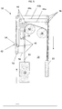
- FIG. 1 Shown in FIG. 1 , is a schematic view of an exemplary traction elevator system 10.
- the elevator system 10 includes an elevator car 12 operatively suspended or supported in a hoistway 14 with one or more load bearing members 16.
- the one or more load bearing members 16 interact with one or more sheaves 18 to be routed around various components of the elevator system 10.
- the one or more load bearing members 16 could also be connected to a counterweight 22, which is used to help balance the elevator system 10 and reduce the difference in belt tension on both sides of the traction sheave during operation.
- the sheaves 18 each have a diameter, which may be the same or different than the diameters of the other sheaves 18 in the elevator system 10. At least one of the sheaves could be a traction sheave 52.
- the traction sheave 52 is driven by a machine (not shown). Movement of drive sheave by the machine drives, moves and/or propels (through traction) the one or more load bearing members 16 that are routed around the traction sheave 52.
- At least one of the sheaves 18 could be a diverter, deflector or idler sheave. Diverter, deflector or idler sheaves are not driven by a machine, but help guide the one or more load bearing members 16 around the various components of the elevator system 10.
- the elevator system 10 could use two or more load bearing members 16 for suspending and/or driving the elevator car 12.
- the elevator system 10 could have various configurations such that either both sides of the one or more load bearing members 16 engage the one or more sheaves 18 or only one side of the one or more load bearing members 16 engages the one or more sheaves 18.
- the embodiment of FIG 1 shows a 1:1 roping arrangement in which the one or more load bearing members 16 terminate at the car 12 and counterweight 22, while other embodiments may utilize other roping arrangements.
- the load bearing members 16 are constructed to have sufficient flexibility when passing over the one or more sheaves 18 to provide low bending stresses, meet belt life requirements and have smooth operation, while being sufficiently strong to be capable of meeting strength requirements for suspending and/or driving the elevator car 12.
- the load bearing member 16 is a rope, formed from a plurality of steel wires 38, which may be arranged into strands 40.
- the load bearing member 16 may be a belt, including a plurality of tension members 24 extending longitudinally along the load bearing member 16 and arranged across a belt width.
- the tension members 24 are at least partially enclosed in a jacket material 28 to restrain movement of the tension members 24 in the belt and to protect the tension members 24.
- the belt has a belt width and a belt thickness, with an aspect ratio of belt width to belt thickness greater than one.
- the belt further includes a back side 34 opposite the traction side 30 and belt edges 36 extending between the traction side 30 and the back side 34.
- the elevator system 10 includes leader system 42.
- the leader system 42 includes a plurality of leader members 44 positioned in the hoistway 14.
- the leader members 44 are secured at the counterweight 22 and are routed over a plurality of leader guides 46, which in some embodiments are pulleys or sheaves.
- the leader system 42 further includes load bearing member guides 48 interactive with the leader members 44 and the load bearing member 16 to prevent sway of the load bearing member 16 in the hoistway 14.
- the leader system 42 includes three leader members 44a, 44b, 44c in a nested configuration.
- nested it is meant that at any point in the hoistway 14, a first leader member 44a is located closest to the load bearing member 16 relative to leader members 44b and 44c, and a third leader member 44c is located furthest from load bearing member 16 relative to leader members 44a and 44b.
- Second leader member 44b is located between leader members 44a and 44c. It is to be appreciated that the use of three leader members 44 is merely exemplary, and that in other embodiments other quantities of leader members 44, such as 2, 4 or 5 leader members 44 may be utilized.
- Each leader member 44 is connected to the counterweight 22 and to a respective load bearing member guide 48.
- the leader member 44 is connected to the load bearing member guide 48 via a guide holder 54, which in some embodiments is a pulley or sheave around which the leader member 44 is at least partially wrapped.
- the guide holder 54 and the load bearing member guide 48 are configured to travel or translate in an upward direction in the hoistway 14 as the counterweight 22 moves downward in the hoistway 14, and likewise the guide holder 54 and the load bearing member guide 48 travel downward in the hoistway 14 when the counterweight 22 travels upward in the hoistway 22.
- the load bearing member guide 48 includes an eyelet 56 through which the associated load bearing member 44 is passed, to guide the load bearing member 44.
- a guide arm 58 may connect the eyelet 56 to the guide holder 54.
- the eyelet 56 of the load bearing member guide 48 is merely an example configuration. In other embodiments, other configurations, such as a hook-shape or the like may be utilized.
- the leader members 44 may have any suitable roping configurations, such as 3:4, 1:2, 1:4, etc. such that the leader members 44 can be positioned between the elevator car 12 and a top of the hoistway 14.
- the roping configurations, and the nested arrangement of the leader members 44 allows for a reduction in the space in the hoistway 14 that the leader members 44 occupy.
- leader members 44 may be interconnected.
- leader member 44c may be coupled to leader member 44b via a connection between leader member 44c and guide holder 54b.
- FIG. 1 the elevator system 10 is illustrated with the elevator car 12 in the lowermost location in the hoistway 14.
- the load bearing member 16 has a length L between the elevator car 12 and the traction sheave 52.
- the load bearing member guide 48b is located at about L/2 from the traction sheave 52
- the load bearing member guide 48c is located at about L/4 from the load bearing member guide 48b.
- the load bearing member guide 48a is located at about L/4 from the load bearing member guide 48b.
- the load bearing member guides 48 are arranged along the load bearing member 16 between the counterweight 22 and the sheave 18 to prevent sway of the load bearing member 16 between the counterweight 22 and the sheave 18.
- load bearing member guides 48 may be utilized to prevent sway of the load bearing member 16 both between the elevator car 12 and the traction sheave 52 and between the load bearing member 16 and the sheave 18.
- the elevator system 10 includes a load bearing member configured as a compensation member 60, for example, a rope or a belt, extending below and connected to the elevator car 12 and the counterweight 22, and routed over a compensation sheave 62.
- the leader system 42 is positioned and configured to prevent sway of the compensation member 60 between the elevator car 12 and the compensation sheave 62 by positioning load bear member guides 48 along the compensation member 60 between the elevator car 12 and the compensation sheave 62.
- the leader system may also be configured to prevent sway of the compensation member 60 between the compensation sheave 62 and the counterweight 22 by positioning load bear member guides 48 along the compensation member 60 between the counterweight 22 and the compensation sheave 62.
- the leader system 42 described herein provides continuous guidance for the load bearing members 16, throughout operation of the elevator system 10, preventing sway of the load bearing members 16, which can cause objectionable noise and/or damage hoistway equipment.
Landscapes
- Engineering & Computer Science (AREA)
- Structural Engineering (AREA)
- Automation & Control Theory (AREA)
- Civil Engineering (AREA)
- Mechanical Engineering (AREA)
- Lift-Guide Devices, And Elevator Ropes And Cables (AREA)
Abstract
A leader system for load bearing member sway prevention of an elevator system includes a plurality of leader members disposed in a hoistway of the elevator system, and a plurality of load bearing member guides each operably connected to at least one leader member of the plurality of leader members. Each load bearing member guide is movable along the hoistway via operation of the elevator system and includes one or more guide elements interactive with a load bearing member of the elevator system to prevent sway of the load bearing member.
Description
- The subject matter disclosed herein relates to elevator systems. More specifically, the subject matter disclosed herein relates to mitigation of sway of suspension and/or driving ropes for elevator systems.
- Elevator systems typically include one or more ropes or other suspension members such as belts from which an elevator car is suspended, and with which the elevator car is driven along a hoistway. Tall buildings in particular, which have elevator systems servicing them, have some sway associated with them. This sway, most often experienced during periods of high winds, can seriously impact elevator performance and, in some instances, damage elevator components. For example, building sway can result in rope sway that, especially when the rope length is shortened as the car runs into an upper or lower landing, has a significant lateral amplitude that causes excessive vertical vibration and noise at the elevator car. Further, rope sway effects experienced at the elevator car are increased at certain floors where the rope sway frequency is at or near the building sway vibratory frequency.
- In some systems, rollers or other devices may be utilized to prevent rope from contacting walls of the hoistway, but such rollers can be costly, especially in buildings with an especially tall rise.
- In one embodiment, a leader system for load bearing member sway prevention of an elevator system includes a plurality of leader members disposed in a hoistway of the elevator system, and a plurality of load bearing member guides each operably connected to at least one leader member of the plurality of leader members. Each load bearing member guide is movable along the hoistway via operation of the elevator system and includes one or more guide elements interactive with a load bearing member of the elevator system to prevent sway of the load bearing member.
- Additionally or alternatively, in this or other embodiments the plurality of leader members are positioned in the hoistway between a top of the hoistway and an elevator car.
- Additionally or alternatively, in this or other embodiments the plurality of leader members are positioned in the hoistway between a bottom of the hoistway and an elevator car.
- Additionally or alternatively, in this or other embodiments the plurality of leader members are positioned in a nested arrangement in the hoistway.
- Additionally or alternatively, in this or other embodiments the plurality of leader members includes three or more leader members.
- Additionally or alternatively, in this or other embodiments each load bearing member guide is operably connected to a leader member via a guide holder.
- Additionally or alternatively, in this or other embodiments the guide holder is a pulley around which the leader member is at least partially wrapped.
- Additionally or alternatively, in this or other embodiments the leader members are configured for connection to a counterweight of the elevator system.
- Additionally or alternatively, in this or other embodiments the load bearing member guides are configured to move along the hoistway in response to movement of the counterweight along the hoistway.
- Additionally or alternatively, in this or other embodiments the load bearing member guide includes an eyelet through which the load bearing member extends.
- In another embodiment, an elevator system includes a hoistway, an elevator car positioned in the hoistway, a load bearing member operably connected to the elevator car to move the elevator car along the hoistway and a leader system to prevent sway of the load bearing member. The leader system includes a plurality of leader members located in the hoistway and a plurality of load bearing member guides each operably connected to at least one leader member of the plurality of leader members. Each load bearing member guide is movable along the hoistway via operation of the elevator system and including one or more guide elements interactive with the load bearing member to prevent sway of the load bearing member.
- Additionally or alternatively, in this or other embodiments the plurality of leader members are located in the hoistway between a top of the hoistway and the elevator car.
- Additionally or alternatively, in this or other embodiments the plurality of leader members are positioned in a nested arrangement in the hoistway.
- Additionally or alternatively, in this or other embodiments the plurality of leader members includes three or more leader members.
- Additionally or alternatively, in this or other embodiments each load bearing member guide is operably connected to a leader member via a guide holder.
- Additionally or alternatively, in this or other embodiments the guide holder is a pulley around which the leader member is at least partially wrapped.
- Additionally or alternatively, in this or other embodiments the leader members are configured for connection to a counterweight of the elevator system.
- Additionally or alternatively, in this or other embodiments the load bearing member guides are configured to move along the hoistway in response to movement of the counterweight along the hoistway.
- Additionally or alternatively, in this or other embodiments the load bearing member guide includes an eyelet through which the load bearing member extends.
- The following descriptions should not be considered limiting in any way. With reference to the accompanying drawings, like elements are numbered alike:
-
FIG. 1 is a schematic view of an embodiment of an elevator system; -
FIG. 2 is a cross-sectional view of an embodiment of a load bearing member for an elevator system; -
FIG. 3 is a cross-sectional view of another embodiment of a load bearing member of an elevator system; -
FIG. 4 is a plan view of an embodiment of a load bearing member guide for an elevator system; -
FIG. 5 is another schematic view of an embodiment of an elevator system; -
FIG. 6 is yet another schematic view of an embodiment of an elevator system; -
FIG. 7 is still another schematic view of an embodiment of an elevator system; -
FIG. 8 is a schematic view of another embodiment of an elevator system; and -
FIG. 9 is a schematic view of yet another embodiment of an elevator system. - A detailed description of one or more embodiments of the disclosed apparatus and method are presented herein by way of exemplification and not limitation with reference to the Figures.
- Shown in
FIG. 1 , is a schematic view of an exemplarytraction elevator system 10. Features of theelevator system 10 that are not required for an understanding of the present invention (such as the guide rails, safeties, etc.) are not discussed herein. Theelevator system 10 includes anelevator car 12 operatively suspended or supported in ahoistway 14 with one or moreload bearing members 16. The one or moreload bearing members 16 interact with one ormore sheaves 18 to be routed around various components of theelevator system 10. The one or moreload bearing members 16 could also be connected to acounterweight 22, which is used to help balance theelevator system 10 and reduce the difference in belt tension on both sides of the traction sheave during operation. - The
sheaves 18 each have a diameter, which may be the same or different than the diameters of theother sheaves 18 in theelevator system 10. At least one of the sheaves could be atraction sheave 52. Thetraction sheave 52 is driven by a machine (not shown). Movement of drive sheave by the machine drives, moves and/or propels (through traction) the one or moreload bearing members 16 that are routed around thetraction sheave 52. At least one of thesheaves 18 could be a diverter, deflector or idler sheave. Diverter, deflector or idler sheaves are not driven by a machine, but help guide the one or moreload bearing members 16 around the various components of theelevator system 10. - In some embodiments, the
elevator system 10 could use two or moreload bearing members 16 for suspending and/or driving theelevator car 12. In addition, theelevator system 10 could have various configurations such that either both sides of the one or moreload bearing members 16 engage the one ormore sheaves 18 or only one side of the one or moreload bearing members 16 engages the one ormore sheaves 18. The embodiment ofFIG 1 shows a 1:1 roping arrangement in which the one or moreload bearing members 16 terminate at thecar 12 andcounterweight 22, while other embodiments may utilize other roping arrangements. - The
load bearing members 16 are constructed to have sufficient flexibility when passing over the one ormore sheaves 18 to provide low bending stresses, meet belt life requirements and have smooth operation, while being sufficiently strong to be capable of meeting strength requirements for suspending and/or driving theelevator car 12. - In some embodiments, such as shown in
FIG. 2 , theload bearing member 16 is a rope, formed from a plurality ofsteel wires 38, which may be arranged intostrands 40. In other embodiments, such as shown inFIG. 3 , theload bearing member 16 may be a belt, including a plurality oftension members 24 extending longitudinally along theload bearing member 16 and arranged across a belt width. Thetension members 24 are at least partially enclosed in ajacket material 28 to restrain movement of thetension members 24 in the belt and to protect thetension members 24. The belt has a belt width and a belt thickness, with an aspect ratio of belt width to belt thickness greater than one. The belt further includes aback side 34 opposite thetraction side 30 andbelt edges 36 extending between thetraction side 30 and theback side 34. - Referring again to
FIG. 1 , to reduce and/or prevent sway of theload bearing members 16 during operation of theelevator system 10, theelevator system 10 includesleader system 42. Theleader system 42 includes a plurality ofleader members 44 positioned in thehoistway 14. Theleader members 44 are secured at thecounterweight 22 and are routed over a plurality ofleader guides 46, which in some embodiments are pulleys or sheaves. Theleader system 42 further includes load bearing member guides 48 interactive with theleader members 44 and theload bearing member 16 to prevent sway of theload bearing member 16 in thehoistway 14. - In the embodiment of
FIG. 1 , theleader system 42 includes threeleader members hoistway 14, afirst leader member 44a is located closest to theload bearing member 16 relative toleader members third leader member 44c is located furthest fromload bearing member 16 relative toleader members Second leader member 44b is located betweenleader members leader members 44 is merely exemplary, and that in other embodiments other quantities ofleader members 44, such as 2, 4 or 5leader members 44 may be utilized. - Each
leader member 44 is connected to thecounterweight 22 and to a respective load bearingmember guide 48. In some embodiments, theleader member 44 is connected to the load bearingmember guide 48 via aguide holder 54, which in some embodiments is a pulley or sheave around which theleader member 44 is at least partially wrapped. Theguide holder 54 and the load bearingmember guide 48 are configured to travel or translate in an upward direction in thehoistway 14 as thecounterweight 22 moves downward in thehoistway 14, and likewise theguide holder 54 and the load bearingmember guide 48 travel downward in thehoistway 14 when thecounterweight 22 travels upward in thehoistway 22. - In some embodiments, such as shown in
FIG. 4 , the load bearingmember guide 48 includes aneyelet 56 through which the associatedload bearing member 44 is passed, to guide theload bearing member 44. Aguide arm 58 may connect theeyelet 56 to theguide holder 54. One skilled in the art will appreciate that theeyelet 56 of the load bearingmember guide 48 is merely an example configuration. In other embodiments, other configurations, such as a hook-shape or the like may be utilized. - Referring again to
FIG. 1 , theleader members 44 may have any suitable roping configurations, such as 3:4, 1:2, 1:4, etc. such that theleader members 44 can be positioned between theelevator car 12 and a top of thehoistway 14. The roping configurations, and the nested arrangement of theleader members 44 allows for a reduction in the space in thehoistway 14 that theleader members 44 occupy. - Further, in some embodiments, the
leader members 44 may be interconnected. For example, as shown inFIG. 1 ,leader member 44c may be coupled toleader member 44b via a connection betweenleader member 44c and guide holder 54b. - Operation of the
elevator system 10 and theleader system 42 will now be described with reference toFIGs. 1 , and5-7 . InFIG. 1 , theelevator system 10 is illustrated with theelevator car 12 in the lowermost location in thehoistway 14. Theload bearing member 16 has a length L between theelevator car 12 and thetraction sheave 52. With theelevator car 12 in this position, the load bearing member guide 48b is located at about L/2 from thetraction sheave 52, and the load bearing member guide 48c is located at about L/4 from the load bearing member guide 48b. In some embodiments, the load bearing member guide 48a is located at about L/4 from the load bearing member guide 48b. - Referring now to
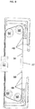
FIG. 5 , as theelevator car 12 travels upward in thehoistway 14 and thecounterweight 22 travels downward in thehoistway 14, theleader members 44 are moved by the movement of thecounterweight 22, such that the guide holders 50 and thus the load bearing member guides 48 are urged upward in thehoistway 14. AtFIG. 6 , with thecounterweight 22 located at its lowermost position in thehoistway 14, the load bearing member guides 48 and the guide holders 50 are located at their uppermost position in thehoistway 14. Referring now toFIG. 7 , as thecounterweight 22 moves upwardly in thehoistway 14, the load bearing member guides 48 and the guide holders 50 move downward in thehoistway 14, and increase a distance between the load bearing member guides 48a, 48b and between load bearing member guides 48b, 48c. - In another embodiment, shown in
FIG. 8 , the load bearing member guides 48 are arranged along theload bearing member 16 between thecounterweight 22 and thesheave 18 to prevent sway of theload bearing member 16 between thecounterweight 22 and thesheave 18. One skilled in the art will readily appreciate that load bearing member guides 48 may be utilized to prevent sway of theload bearing member 16 both between theelevator car 12 and thetraction sheave 52 and between theload bearing member 16 and thesheave 18. - In yet another embodiment, shown in
FIG. 9 , theelevator system 10 includes a load bearing member configured as acompensation member 60, for example, a rope or a belt, extending below and connected to theelevator car 12 and thecounterweight 22, and routed over acompensation sheave 62. In this embodiment, theleader system 42 is positioned and configured to prevent sway of thecompensation member 60 between theelevator car 12 and thecompensation sheave 62 by positioning load bear member guides 48 along thecompensation member 60 between theelevator car 12 and thecompensation sheave 62. Additionally or alternatively, the leader system may also be configured to prevent sway of thecompensation member 60 between thecompensation sheave 62 and thecounterweight 22 by positioning load bear member guides 48 along thecompensation member 60 between thecounterweight 22 and thecompensation sheave 62. - The
leader system 42 described herein provides continuous guidance for theload bearing members 16, throughout operation of theelevator system 10, preventing sway of theload bearing members 16, which can cause objectionable noise and/or damage hoistway equipment. - The term "about" is intended to include the degree of error associated with measurement of the particular quantity based upon the equipment available at the time of filing the application. For example, "about" can include a range of ± 8% or 5%, or 2% of a given value.
- The terminology used herein is for the purpose of describing particular embodiments only and is not intended to be limiting of the present disclosure. As used herein, the singular forms "a", "an" and "the" are intended to include the plural forms as well, unless the context clearly indicates otherwise. It will be further understood that the terms "comprises" and/or "comprising," when used in this specification, specify the presence of stated features, integers, steps, operations, elements, and/or components, but do not preclude the presence or addition of one or more other features, integers, steps, operations, element components, and/or groups thereof.
- While the present disclosure has been described with reference to an exemplary embodiment or embodiments, it will be understood by those skilled in the art that various changes may be made and equivalents may be substituted for elements thereof without departing from the scope of the present disclosure. In addition, many modifications may be made to adapt a particular situation or material to the teachings of the present disclosure without departing from the essential scope thereof. Therefore, it is intended that the present disclosure not be limited to the particular embodiment disclosed as the best mode contemplated for carrying out this present disclosure, but that the present disclosure will include all embodiments falling within the scope of the claims.
Claims (11)
- A leader system for load bearing member sway prevention of an elevator system, comprising:a plurality of leader members disposed in a hoistway of the elevator system; anda plurality of load bearing member guides each operably connected to at least one leader member of the plurality of leader members, each load bearing member guide movable along the hoistway via operation of the elevator system and including one or more guide elements interactive with a load bearing member of the elevator system to prevent sway of the load bearing member.
- The leader system of claim 1, wherein the plurality of leader members are disposed in the hoistway between a top of the hoistway and an elevator car.
- The leader system of claim 1 or 2, wherein the plurality of leader members are disposed in the hoistway between a bottom of the hoistway and an elevator car.
- The leader system of any of claims 1 to 3, wherein the plurality of leader members are disposed in a nested arrangement in the hoistway.
- The leader system of any of claims 1 to 4, wherein the plurality of leader members comprises three or more leader members.
- The leader system of any of claims 1 to 5, wherein each load bearing member guide is operably connected to a leader member via a guide holder.
- The leader system of any of claims 1 to 6, wherein the guide holder is a pulley around which the leader member is at least partially wrapped.
- The leader system of any of claims 1 to 7, wherein the leader members are configured for connection to a counterweight of the elevator system.
- The leader system of claim 8, wherein the load bearing member guides are configured to move along the hoistway in response to movement of the counterweight along the hoistway.
- The leader system of any of claims 1 to 9, wherein the load bearing member guide includes an eyelet through which the load bearing member extends.
- An elevator system, comprising:a hoistway;an elevator car disposed in the hoistway;a load bearing member operably connected to the elevator car to move the elevator car along the hoistway; anda leader system to prevent sway of the load bearing member according to any of the previous claims.
Applications Claiming Priority (1)
| Application Number | Priority Date | Filing Date | Title |
|---|---|---|---|
| US201762527292P | 2017-06-30 | 2017-06-30 |
Publications (1)
| Publication Number | Publication Date |
|---|---|
| EP3424863A1 true EP3424863A1 (en) | 2019-01-09 |
Family
ID=62814898
Family Applications (1)
| Application Number | Title | Priority Date | Filing Date |
|---|---|---|---|
| EP18180199.4A Withdrawn EP3424863A1 (en) | 2017-06-30 | 2018-06-27 | Multiple leaders for load bearing member sway reduction |
Country Status (5)
| Country | Link |
|---|---|
| US (1) | US20190002242A1 (en) |
| EP (1) | EP3424863A1 (en) |
| KR (1) | KR20190003378A (en) |
| CN (1) | CN109205446A (en) |
| AU (1) | AU2018204642A1 (en) |
Cited By (1)
| Publication number | Priority date | Publication date | Assignee | Title |
|---|---|---|---|---|
| EP3517475A1 (en) * | 2017-12-07 | 2019-07-31 | Otis Elevator Company | Elevator rope sway restriction device |
Citations (4)
| Publication number | Priority date | Publication date | Assignee | Title |
|---|---|---|---|---|
| US20060266591A1 (en) * | 2003-11-14 | 2006-11-30 | Weidong Zhu | System and method for damping vibrations in elevator cables |
| WO2009116985A1 (en) * | 2008-03-17 | 2009-09-24 | Otis Elevator Company | Autonomous sway damper for use in an elevator system |
| JP2015151230A (en) * | 2014-02-13 | 2015-08-24 | 株式会社日立製作所 | Main rope vibration stopping device for elevator |
| JP2015168533A (en) * | 2014-03-07 | 2015-09-28 | 株式会社日立製作所 | Elevator device |
Family Cites Families (3)
| Publication number | Priority date | Publication date | Assignee | Title |
|---|---|---|---|---|
| JPH082853A (en) * | 1994-06-22 | 1996-01-09 | Hitachi Building Syst Eng & Service Co Ltd | elevator |
| JPH0986826A (en) * | 1995-09-25 | 1997-03-31 | Hitachi Ltd | Rope elevator |
| JP2011073836A (en) * | 2009-09-30 | 2011-04-14 | Hitachi Ltd | Rope type elevator device |
-
2018
- 2018-06-26 AU AU2018204642A patent/AU2018204642A1/en not_active Abandoned
- 2018-06-27 EP EP18180199.4A patent/EP3424863A1/en not_active Withdrawn
- 2018-06-27 KR KR1020180073925A patent/KR20190003378A/en not_active Ceased
- 2018-06-29 US US16/023,953 patent/US20190002242A1/en not_active Abandoned
- 2018-06-29 CN CN201810722281.XA patent/CN109205446A/en active Pending
Patent Citations (4)
| Publication number | Priority date | Publication date | Assignee | Title |
|---|---|---|---|---|
| US20060266591A1 (en) * | 2003-11-14 | 2006-11-30 | Weidong Zhu | System and method for damping vibrations in elevator cables |
| WO2009116985A1 (en) * | 2008-03-17 | 2009-09-24 | Otis Elevator Company | Autonomous sway damper for use in an elevator system |
| JP2015151230A (en) * | 2014-02-13 | 2015-08-24 | 株式会社日立製作所 | Main rope vibration stopping device for elevator |
| JP2015168533A (en) * | 2014-03-07 | 2015-09-28 | 株式会社日立製作所 | Elevator device |
Cited By (1)
| Publication number | Priority date | Publication date | Assignee | Title |
|---|---|---|---|---|
| EP3517475A1 (en) * | 2017-12-07 | 2019-07-31 | Otis Elevator Company | Elevator rope sway restriction device |
Also Published As
| Publication number | Publication date |
|---|---|
| US20190002242A1 (en) | 2019-01-03 |
| AU2018204642A1 (en) | 2019-01-17 |
| CN109205446A (en) | 2019-01-15 |
| KR20190003378A (en) | 2019-01-09 |
Similar Documents
| Publication | Publication Date | Title |
|---|---|---|
| US11591188B2 (en) | Elevator system roping arrangement | |
| JP4786121B2 (en) | Elevator equipment | |
| EP1357075B1 (en) | Cage device for double deck elevators | |
| CN1882492B (en) | Elevator pulley | |
| EP1631516B1 (en) | Elevator system without a moving counterweight | |
| CN103796942A (en) | Suspension arrangement and guide shoe arrangement for elevator | |
| US20120067674A1 (en) | Elevator with an elevator cage and a counterweight | |
| US7481299B2 (en) | Elevator with compensating device | |
| CN103370271B (en) | Comprise the elevator device that 4:1 lanyard is arranged | |
| KR20080055706A (en) | Elevator equipment | |
| JP5161563B2 (en) | elevator | |
| CN110002319B (en) | Elevator rope sway limiting device | |
| US20190002242A1 (en) | Multiple leaders for load bearing member sway reduction | |
| CN103171944B (en) | The portable cord cable device of elevator | |
| CN110894039B (en) | Traveling cable support device for elevator | |
| US20180179023A1 (en) | Increased traction of elevator system belt | |
| EP1602613A1 (en) | Counterbalancing self-running elevator | |
| JP6684473B2 (en) | Elevator with multiple counterweights | |
| US10689229B2 (en) | Elevator system suspension member termination | |
| JP2011162291A (en) | Rope type elevator | |
| US11214464B2 (en) | Elevator seismic performance apparatus | |
| EP1808399B1 (en) | Belt-climbing elevator having drive in counterweight | |
| EP1862420A1 (en) | Elevator apparatus | |
| HK1190688B (en) | Elevator system including a 4:1 roping arrangement |
Legal Events
| Date | Code | Title | Description |
|---|---|---|---|
| PUAI | Public reference made under article 153(3) epc to a published international application that has entered the european phase |
Free format text: ORIGINAL CODE: 0009012 |
|
| AK | Designated contracting states |
Kind code of ref document: A1 Designated state(s): AL AT BE BG CH CY CZ DE DK EE ES FI FR GB GR HR HU IE IS IT LI LT LU LV MC MK MT NL NO PL PT RO RS SE SI SK SM TR |
|
| AX | Request for extension of the european patent |
Extension state: BA ME |
|
| STAA | Information on the status of an ep patent application or granted ep patent |
Free format text: STATUS: THE APPLICATION IS DEEMED TO BE WITHDRAWN |
|
| 18D | Application deemed to be withdrawn |
Effective date: 20190710 |