EP3424792A1 - Vehicular cooling device - Google Patents
Vehicular cooling device Download PDFInfo
- Publication number
- EP3424792A1 EP3424792A1 EP16892439.7A EP16892439A EP3424792A1 EP 3424792 A1 EP3424792 A1 EP 3424792A1 EP 16892439 A EP16892439 A EP 16892439A EP 3424792 A1 EP3424792 A1 EP 3424792A1
- Authority
- EP
- European Patent Office
- Prior art keywords
- blockers
- opening
- outside air
- cooling device
- travelling
- Prior art date
- Legal status (The legal status is an assumption and is not a legal conclusion. Google has not performed a legal analysis and makes no representation as to the accuracy of the status listed.)
- Granted
Links
Images










Classifications
-
- B—PERFORMING OPERATIONS; TRANSPORTING
- B60—VEHICLES IN GENERAL
- B60C—VEHICLE TYRES; TYRE INFLATION; TYRE CHANGING; CONNECTING VALVES TO INFLATABLE ELASTIC BODIES IN GENERAL; DEVICES OR ARRANGEMENTS RELATED TO TYRES
- B60C17/00—Tyres characterised by means enabling restricted operation in damaged or deflated condition; Accessories therefor
-
- B—PERFORMING OPERATIONS; TRANSPORTING
- B61—RAILWAYS
- B61C—LOCOMOTIVES; MOTOR RAILCARS
- B61C17/00—Arrangement or disposition of parts; Details or accessories not otherwise provided for; Use of control gear and control systems
-
- B—PERFORMING OPERATIONS; TRANSPORTING
- B60—VEHICLES IN GENERAL
- B60H—ARRANGEMENTS OF HEATING, COOLING, VENTILATING OR OTHER AIR-TREATING DEVICES SPECIALLY ADAPTED FOR PASSENGER OR GOODS SPACES OF VEHICLES
- B60H1/00—Heating, cooling or ventilating devices
- B60H1/00357—Air-conditioning arrangements specially adapted for particular vehicles
- B60H1/00371—Air-conditioning arrangements specially adapted for particular vehicles for vehicles carrying large numbers of passengers, e.g. buses
-
- B—PERFORMING OPERATIONS; TRANSPORTING
- B60—VEHICLES IN GENERAL
- B60H—ARRANGEMENTS OF HEATING, COOLING, VENTILATING OR OTHER AIR-TREATING DEVICES SPECIALLY ADAPTED FOR PASSENGER OR GOODS SPACES OF VEHICLES
- B60H1/00—Heating, cooling or ventilating devices
- B60H1/00421—Driving arrangements for parts of a vehicle air-conditioning
- B60H1/00428—Driving arrangements for parts of a vehicle air-conditioning electric
-
- B—PERFORMING OPERATIONS; TRANSPORTING
- B60—VEHICLES IN GENERAL
- B60H—ARRANGEMENTS OF HEATING, COOLING, VENTILATING OR OTHER AIR-TREATING DEVICES SPECIALLY ADAPTED FOR PASSENGER OR GOODS SPACES OF VEHICLES
- B60H1/00—Heating, cooling or ventilating devices
- B60H1/24—Ventilating devices where the heating or cooling is irrelevant
- B60H1/248—Air-extractors, air-evacuation from the vehicle interior
-
- H—ELECTRICITY
- H02—GENERATION; CONVERSION OR DISTRIBUTION OF ELECTRIC POWER
- H02K—DYNAMO-ELECTRIC MACHINES
- H02K9/00—Arrangements for cooling or ventilating
- H02K9/02—Arrangements for cooling or ventilating by ambient air flowing through the machine
- H02K9/04—Arrangements for cooling or ventilating by ambient air flowing through the machine having means for generating a flow of cooling medium
- H02K9/06—Arrangements for cooling or ventilating by ambient air flowing through the machine having means for generating a flow of cooling medium with fans or impellers driven by the machine shaft
-
- B—PERFORMING OPERATIONS; TRANSPORTING
- B60—VEHICLES IN GENERAL
- B60L—PROPULSION OF ELECTRICALLY-PROPELLED VEHICLES; SUPPLYING ELECTRIC POWER FOR AUXILIARY EQUIPMENT OF ELECTRICALLY-PROPELLED VEHICLES; ELECTRODYNAMIC BRAKE SYSTEMS FOR VEHICLES IN GENERAL; MAGNETIC SUSPENSION OR LEVITATION FOR VEHICLES; MONITORING OPERATING VARIABLES OF ELECTRICALLY-PROPELLED VEHICLES; ELECTRIC SAFETY DEVICES FOR ELECTRICALLY-PROPELLED VEHICLES
- B60L2200/00—Type of vehicles
- B60L2200/26—Rail vehicles
Definitions
- the present disclosure relates to a vehicular cooling device.
- a vehicular cooling device mounted on a vehicle draws outside air that is air outside the vehicle, and sends the drawn outside air toward an electronic device that is a cooling target, thereby cooling the electronic device.
- the outside air may contain foreign objects, for example, rain, snow, or dust.
- Patent Literature 1 discloses a cooling device that discharges foreign objects from a discharge duct provided at an outlet of a centrifugal fan to keep the foreign objects from contacting the electronic device.
- Patent Literature 1 Examined Japanese Patent Application Publication No. S58-014345
- the present disclosure is made in view of the above, and thus an objective of the present disclosure is to provide a simplified structure for removing the foreign objects contained in the outside air.
- a vehicular cooling device including an opening, a discharge port, an air channel, a fan, and first blockers.
- the opening is formed in, among surfaces of the housing in which a cooling target is housed, a surface parallel to a travelling direction of a vehicle provided with the housing.
- the outside air flows through the opening in the housing.
- the discharge port is formed in a surface of the housing, and the outside air is discharged through the discharge port.
- the air channel is formed inside the housing, and includes one end connected to the opening and another end connected to the discharge port.
- the fan is provided inside the air channel to supply to the cooling target the outside air flowing through the opening into the air channel and discharge through the discharge port the outside that has undergone heat exchange with the cooling target.
- the first blockers are provided in the opening and spaced apart in the travelling direction.
- the first blockers are provided in the opening and spaced apart from one another in the travelling direction.
- Each first blocker extends in a direction perpendicular to both of the travelling direction and an inflow direction of the outside air, and includes a first member and a second member.
- the first member is a plate-like member having a main surface intersecting the travelling direction.
- the first member and the second member of each first blocker are symmetric with respect to a plane perpendicular to the travelling direction, and have a travelling-direction spacing therebetween that increases along the inflow direction of the outside air.
- the present disclosure includes first blockers each including a first member and a second member.
- the first member is a plate-like member extending in a direction perpendicular to both of the travelling direction of the vehicle and the inflow direction of the outside air, and having a main surface intersecting the travelling direction.
- the first member and the second member are symmetric with respect to a plane perpendicular to the travelling direction.
- Such first blockers are provided in the opening and spaced apart in the travelling direction, thereby providing a simplified structure for removing foreign objects contained in the outside air.
- FIG. 1 is a cross-sectional view of a vehicular cooling device according to Embodiment 1 of the present disclosure.
- the cross-sectional view in FIG. 1 illustrates a cross-section of the vehicular cooling device 1 (hereinafter referred to as a cooling device) that is in a plane perpendicular to a travelling direction of a vehicle.
- the vehicle for example a railway vehicle, is provided with a housing 2 inside which a cooling target 3 is housed.
- the housing 2 is a body of the railway vehicle itself.
- FIG. 1 is a cross-sectional view of a vehicular cooling device according to Embodiment 1 of the present disclosure.
- the cross-sectional view in FIG. 1 illustrates a cross-section of the vehicular cooling device 1 (hereinafter referred to as a cooling device) that is in a plane perpendicular to a travelling direction of a vehicle.
- the vehicle for example a railway vehicle, is provided with a housing 2 inside which a cooling target 3 is housed.
- the cooling device 1 includes an opening 10 and a discharge port 14.
- the opening 10 is formed in, among surfaces of the housing 2, a surface parallel to the travelling direction of the vehicle, which surface is one side surface of the body in the example of FIG. 1 .
- the discharge port 14 through which the outside air is discharged is formed in a surface of the housing 2, which surface is another side surface of the body in the example of FIG. 1 .
- the cooling device 1 further includes an air channel 12 and a fan 13.
- the air channel 12 is formed inside the housing 2, and includes one end connected to the opening 10 and another end connected to the discharge port 14.
- the fan 13 is provided inside the air channel 12 to supply the outside air to the cooling target 3 and discharge through the discharge port 14 the outside air that has undergone heat exchange with the cooling target 3.
- the opening 10 penetrates the housing 2 in the X-axis direction, and includes a first opening plane 10a that is located on the outer side of the housing 2 and a second opening plane 10b that is located on the air channel 12 side.
- the inflow direction of the outside air is a direction from the first opening plane 10a to the second opening plane 10b, that is, the positive X-axis direction.
- the outside air flows into the opening 10, passes through the opening 10, and flows into the air channel 12.
- the outside air flowing into the air channel 12 is supplied by the fan 13 to the cooling target 3, and the outside air that has undergone heat exchange with the cooling target 3 is discharged through the discharge port 14 to the outside of the housing 2.
- FIG. 1 the example of FIG.
- the fan 13 is a centrifugal fan.
- the cooling target 3 may be any electronic device or heat sink, and the cooling target 3 may be, for example, an electric reactor or fins formed on a board with the electronic device mounted thereon.
- a single vehicle may be equipped with a plurality of cooling targets 3, and the cooling device 1 may be provided for each of the cooling targets 3.
- First blockers 11 are provided in the opening 10 and spaced apart in the Y-axis direction.
- the first blockers 11 provided in the opening 10 remove foreign objects, such as rain, snow, or dust, that are substances other than air contained in the outside air. This enables simplifying a structure for removal of the foreign objects contained in the outside air.
- FIG. 2 is a perspective view of the opening according to Embodiment 1.
- FIG. 3 is a cross-sectional view of the opening according to Embodiment 1.
- Eight first blockers 11 are spaced apart in the Y-axis direction in the example of FIGS. 2 and 3 , but the number of the first blockers 11 may be any number that is two or more.
- Each first blocker 11 includes a first member 11a and a second member 11b.
- the first member 11a is a plate-like member extending in a direction perpendicular to both of the travelling direction and the inflow direction of the outside air, that is, extends in a Z-axis direction, and having a main surface intersecting the travelling direction of the vehicle, that is, the Y-axis direction.
- the first member 11a and the second member 11b are symmetric with respect to a plane perpendicular to the Y-axis direction.
- the first members 11a and the second members 11b extend in a direction of spacing between an upper surface 10c located on a vertically upper side of the opening 10 and a lower surface 10d located on a vertically lower side of the opening 10.
- the Y-axis-direction spacing between the first member 11a and the second member 11b that are included in the same first blocker 11 increases in the inflow direction of the outside air, that is, in the positive X-axis direction.
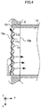
- FIG. 4 is a drawing illustrating a flow of air and a flow of foreign objects in the opening according to Embodiment 1.
- the dashed arrows indicate the flow of air
- the solid arrow indicates the flow of foreign objects.
- the vehicle travels in the positive Y-axis direction in the example of FIG. 4 .
- the outside air has a velocity opposite to the travelling direction relative to the vehicle.
- the fan 13 Upon activation of the fan 13, the air thus passes through the space between the first blockers 11 and flows into the air channel 12, as illustrated by the dashed arrows in FIG. 4 .
- the foreign objects having higher specific gravity than air are displaced greatly in the travelling direction due to inertial force, strike against the first members 11a and the second members 11b, and are forced outward from the housing 2.
- the foreign objects repeatedly strike against the first members 11a and the second members 11b, and move backward from the opening 10 along the travelling direction of the vehicle without flowing into the air channel 12.
- the foreign objects similarly move backward from the opening 10 along the travelling direction of the vehicle without flowing into the air channel 12 since the first member 11a and the second member 11b of each first blocker 11 are symmetric to each other with respect to a plane.
- the first blocker 11 has a cross-section perpendicular to a direction in which the first member 11a extends, that is, a cross-section parallel to an XY-plane.
- the cross-section has a V-shape formed by the first member 11a and the second member 11b. Adjustment of a vertex angle of the V-shape, an angle ⁇ 1 in FIG. 3 , can achieve a lower amount of the foreign objects flowing into the air channel 12.
- FIG. 5 is a graph illustrating a relationship between a vertex angle and an inflow rate of the foreign objects, according to Embodiment 1.
- the graph indicates a result of a three-dimensional fluid simulation in which particles having size and density equivalent to powder snow were generated as the foreign objects to move oppositely to the travelling direction, and the amount of the foreign objects flowing into the air channel 12 is measured.
- the graph has a horizontal axis indicating the angle ⁇ 1 and a vertical axis indicating the inflow rate of the foreign objects.
- the inflow rate of the foreign objects is a value expressed as a ratio of the amount of the foreign objects flowing through the space between the first blockers 11 into the air channel 12 to the amount of the foreign objects flowing into the air channel 12 when plates having a main surface parallel to the YZ-plane are arranged in the opening 10 and spaced apart in the Y-axis direction.
- This simulation was performed at each angle with the widths A of the first blockers 11 in the X-axis direction in FIG. 3 set to the same value, and with the sum of the values of gaps B between the first blockers 11 in the Y-axis direction in FIG. 3 set to the same value.
- the example of FIG. 5 shows that the inflow rate is less than 1 in the range of 60° ⁇ ⁇ 1 ⁇ 150°, and thus setting the angle ⁇ 1 in the range of 60° ⁇ ⁇ 1 ⁇ 150° is preferable. Setting the angle ⁇ 1 in the range of 90° ⁇ ⁇ 1 ⁇ 120° is preferable to further lower the inflow rate.
- FIG. 6 is a drawing illustrating a lower surface of the opening according to Embodiment 1.
- Recessed portions 15 for positioning are formed on the inside of the lower surface 10d of the opening 10, that is, a side facing an inner space of the opening 10.
- recessed portions 15 are formed on the inside of the upper surface of the opening 10. Engagement of the first blockers 11 in the recessed portions 15 at both ends of the first blockers 11 in the Z-axis direction fastens the first blockers 11 in the opening 10.
- the first blockers 11 can be fastened in the opening 10 by engagement of the first blockers 11 with the recessed portions 15 formed in two surfaces that are on the inside of the opening 10 and intersect the direction in which the first members 11a extend. Forming the recessed portions 15 enables easy positioning of the first blockers 11 in manufacture of the cooling device 1.
- the opening 10 and the first blockers 11 can be manufactured separately.
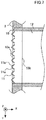
- FIG. 7 is a cross-sectional view of a variation of the opening according to Embodiment 1. As illustrated in FIG. 7 , at least a portion of each first blocker 11 may project outside the housing 2 from the first opening plane 10a. This also applies to embodiments below. Arranging the first blockers 11 such that at least a portion of each first blocker 11 projects outside the housing 2 from the first opening plane 10a can achieve a lower amount of the foreign objects flowing into the air channel 12.
- the first blockers 11 described above are each a V-shaped member that is formed by folding a single plate-like member and has a V-shape in a cross-section parallel to the XY-plane.
- the shape of the first blockers 11 is not limited to that of the above-described example.
- Each first blocker 11 may include the first member 11a and the second member 11b that are narrowly spaced apart in the Y-axis direction in the first opening plane 10a. The spacing between the first member 11a and the second member 11b in the first opening plane 10a can be determined in accordance with the result of simulation on the amount of the foreign objects flowing into the air channel 12.
- FIGS. 8 and 9 are cross-sectional views of variations of the opening according to Embodiment 1. As illustrated in FIG.
- each first blocker 11 may have a trapezoidal shape in a cross-section parallel to the XY-plane.
- This trapezoidal shape may be a shape including, except for a lower base, inclined surfaces that are the first member 11a and the second member 11b and an upper base that is a connection member 11c.
- the connection member 11c is a plate having a main surface parallel to the YZ-plane.
- the first blocker 11 may include the first member 11a, the second member 11b, and a connection member 11d having an arc shape in a cross-section parallel to the XY-plane. This also applies to embodiments below.
- FIG. 10 is a cross-sectional view of a variation of the vehicular cooling device according to Embodiment 1.
- the cooling device 1 is provided vertically downward from a body 4.
- the air channel 12 forms a portion of the housing 2.
- the housing 2 in which the cooling target 3 is housed is mounted vertically below the body 4 through a suspension member 5 and a not-illustrated fastener member.
- the fan 13 is an axial fan in the example of FIG. 10 .
- the opening 10 includes the first opening plane 10a and the second opening plane 10b that are perpendicular to the X-axis direction, and the first blockers 11 are provided in the opening 10.
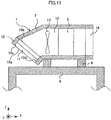
- FIG. 11 is a cross-sectional view of another variation of the vehicular cooling device according to Embodiment 1.
- the cooling device 1 is provided vertically above the body 4.
- the air channel 12 forms a portion of the housing 2.
- the housing 2 in which the cooling target 3 is housed is mounted vertically above the body 4 through a support member 6 and a not-illustrated fastener member.
- the fan 13 is an axial fan in the example of FIG. 11 .
- the first opening plane 10a is inclined toward a ceiling side of the body 4 with respect to a plane parallel to the XY-plane.
- the arrangement of the first opening plane 10a in a position illustrated in FIG. 11 can achieve a lower amount of the foreign objects flowing into the air channel 12.
- the cooling device 1 includes the first blockers 11 that include the first members 11a and the second members 11b and are provided in the opening 10 and spaced apart in the travelling direction, thereby providing a simplified structure for removing the foreign objects contained in the outside air without the need for providing a mechanism for removal of the foreign objects in the interior of the vehicle.
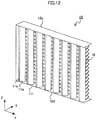
- FIG. 12 is a perspective view of an opening according to Embodiment 2 of the present disclosure.
- the opening 10 according to Embodiment 2 includes second blockers 16 located closer to the air channel 12 than the first blockers 11.
- the second blockers 16 are plate-like members extending in the travelling direction, that is, the Y-axis direction, and spaced apart in the direction perpendicular to both of the travelling direction of the vehicle and the inflow direction of the outside air, that is, the Z-axis direction.
- the spacing between the second blockers 16 and the lower surface 10d increases in the positive X-axis direction.
- the foreign objects passing through the space between the first blockers 11 strike against the second blockers 16, and then slow down and fall vertically downward, thereby suppressing or preventing inflow of the foreign objects into the air channel 12.
- arranging the horizontally extending second blockers 16 at positions closer to the air channel 12 than the first blockers 11 can suppress or prevent the inflow of the foreign objects into the air channel 12.
- the cooling device 1 with the first blockers 11 as well as the second blockers 16 according to Embodiment 2 can further lower the amount of the foreign objects flowing into the air channel 12.
- FIG. 13 is a perspective view of an opening according to Embodiment 3 of the present disclosure. A side surface of the opening 10 and some of the first blockers 11 are omitted in FIG. 13 .
- FIG. 14 is a cross-sectional view of the opening according to Embodiment 3.
- the opening 10 according to Embodiment 3 further includes third blockers 21 spaced apart in the Y-axis direction at positions to block a flow path of the outside air that passes through a space between the first blockers 11 toward the air channel 12.
- the number of the third blockers 21 can be any number.
- Each third blocker 21 includes a third member 21a and a fourth member 21b.
- the third member 21a is a plate-like member extending in the direction perpendicular to both of the travelling direction and the inflow direction of the outside air, that is, the Z-axis direction, and having a main surface intersecting the Y-axis direction.
- the third member 21a and the fourth member 21b are symmetric with respect to a plane perpendicular to the Y-axis direction.
- the Y-axis-direction spacing between the third member 21a and the fourth member 21b decreases in the inflow direction of the outside air, that is, in the positive X-axis direction.
- the third blockers 21 are provided such that points of connection between the third members 21a and the fourth members 21b in the lower surface lOd are located on straight lines parallel to the X-axis and passing through the midpoints of the spaces between the first blockers 11.
- the first blockers 11 and the third blockers 21 are provided in the opening 10 in the example of FIGS. 13 and 14 , but any additional number of third blockers 21 may be provided.
- the additional third blockers 21 are provided at positions to block a flow path of the outside air that flows in the positive X-axis direction through spaces between the third blockers 21 that are adjacent to the additional third blockers 21 and located on the first opening plane 10a side with respect to the additional third blockers 21.
- the additional third blockers 21 are located on the lower surface 10d such that the points of connection between the third member 21a and the fourth member 21b are on straight lines parallel to the X-axis and passing through the midpoints of the spaces between the third blockers 21.
- FIG. 15 is a drawing illustrating a flow of air and a flow of foreign objects in the opening according to Embodiment 3.
- the dashed arrows indicate the flow of air
- the solid arrow indicates the flow of foreign objects.
- the foreign objects for example, water droplets or small stones, having a volume and a density that exceed a predetermined value may pass through the space between the first blockers 11.
- the foreign objects passing through the space between the first blockers 11 strike against the third blockers 21 and then slow down.
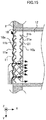
- the third blockers 21 have the recessed parts on the first opening plane 10a side, and thus air resides near the recessed parts. The foreign objects that strike against the third blockers 21 thus fall vertically along the third blockers 21, thus avoiding the entry of the foreign objects into the air channel 12.
- each first blocker 11 has a cross-section parallel to the XY-plane and having a V-shape formed by the first member 11a and the second member 11b.
- each third blocker 21 has a cross-section perpendicular to the direction in which the third member 21a extends, that is, a cross-section parallel to the XY-plane.
- the cross-section has a V-shape formed by the third member 21a and the fourth member 21b.
- Adjustment of a vertex angle of the V-shape, angles ⁇ 1 and ⁇ 2 in FIG. 14 can achieve a lower amount of the foreign objects flowing into the air channel 12. Setting the angles ⁇ 1 and ⁇ 2 in the range of angles greater than 60° and less than 150° is preferable as in Embodiment 1.
- the first blockers 11 are each formed by folding a single plate-like member, and have the recessed parts on the second opening plane 10b side. This secures a flow path for air passing through the spaces between the first blockers 11 toward spaces between the third blockers 21, even if the opening 10 has a narrow width in the X-axis direction.
- FIG. 16 is a cross-sectional view of a variation of the opening according to Embodiment 3.
- the width of the first blockers 11 in the Y-axis direction is the same as the width of the third blockers 21 in the Y-axis direction in the example of FIGS. 13 to 15 , but the width of the first blockers 11 in the Y-axis direction may be different from the width of the third blockers 21 in the Y-axis direction.
- the width D of the third blockers 21 in the Y-axis direction is greater than the width C of the first blockers 11 in the Y-axis direction.
- the shape of the third blockers 21 may be similar to the shapes of the first blockers 11 illustrated in FIGS. 8 and 9 , and is not limited to the above-described examples.
- the first blockers 11 and the third blockers 21 may be fastened to the opening 10 in any manner. Similarly to Embodiment 1, the first blockers 11 and the third blockers 21 can be fastened to the opening 10 with the first blockers 11 and the third blockers 21 engaged in the recessed portions.
- the recessed portions are formed in two surfaces on the inside of the opening 10, and the two surfaces intersect the direction in which the first members 11a extend.
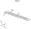
- FIG. 17 is a drawing illustrating a lower surface of the opening according to Embodiment 3.
- First recessed portions 17 and second recessed portions 18 for positioning are formed on the inside of the lower surface 10d of the opening 10.
- the first recessed portions 17 and the second recessed portions 18 are also formed on the inside of the upper surface 10c of the housing 10.
- first blockers 11 in the first recessed portions 17 at both ends of the first blockers 11 in the Z-axis direction fastens the first blockers 11 in the opening 10.
- Engagement of the third blockers 21 in the second recessed portions 18 at both ends of the third blockers 11 in the Z-axis direction fastens the third blockers 21 in the opening 10.
- Forming the first recessed portions 17 and the second recessed portions 18 enables easy positioning of the first blockers 11 and the third blockers 21 in manufacture of the cooling device 1.
- the opening 10, the first blockers 11, and the third blockers 21 can be manufactured separately.
- the cooling device 1 with the first blockers 11 as well as the third blockers 21 according to Embodiment 3 can further lower the amount of the foreign objects flowing into the air channel 12.
- FIG. 18 is a perspective view of an opening according to Embodiment 4 of the present disclosure.
- FIG. 19 is a perspective view of a variation of the opening according to Embodiment 4. A side surface of the opening 10 and some of the first blockers 11 are omitted in FIGS. 18 and 19 .
- the opening 10 according to Embodiment 4 further includes a shielding surface 19 extending from the lower surface 10d toward the upper surface 10c of the opening 10 to block a portion of the second opening plane 10b.
- the shielding surface 19 is formed in a region of connection between the opening 10 and the air channel 12.
- the opening 10 illustrated in FIG. 18 is the opening 10 according to Embodiment 3 provided with the shielding surface 19.
- the opening 10 illustrated in FIG. 19 is the opening 10 according to Embodiment 1 provided with the shielding surface 19.
- the shielding surface 19 may be provided in the opening 10 of the cooling device 1 according to Embodiment 2.
- Providing the shielding surface 19 can suppress or prevent inflow of the foreign objects falling down on the lower surface 10d into the air channel 12 along the lower surface 10d.
- the cooling device 1 with the shielding surface 19 according to Embodiment 4 can further lower the amount of the foreign objects flowing into the air channel 12.
- FIG. 20 is a perspective view of an opening according to Embodiment 5 of the present disclosure.
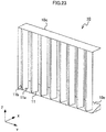
- FIG. 21 is a perspective view of a variation of the opening according to Embodiment 5.
- a side surface of the opening 10 and some of the first blockers 11 are omitted in FIGS. 20 and 21 .
- the opening 10 according to Embodiment 5 is an opening formed by providing the lower surface 10d of the opening 10 according to Embodiments 1 to 4 with holes 20 through which the foreign objects contained in the outside air that flows into the opening 10 are discharged.
- the holes 20 may have any shape, the holes 20 have a shape and a cross-sectional area that allow the foreign objects to be discharged.
- the opening 10 illustrated in FIG. 20 is obtained by forming the holes 20 in a region between the third members 21a and the fourth members 21b in the lower surface 10d of the opening 10 according to Embodiment 3.
- the opening 10 illustrated in FIG. 21 is obtained by forming the holes 20 through the lower surface 10d of the opening 10 according to Embodiment 4 illustrated in FIG. 19 in a region contacting the shielding surface 19.
- the holes 20 may be formed through the lower surface 10d of the opening 10 according to Embodiment 2 or 3 or the lower surface 10d of the opening 10 according to Embodiment 4 illustrated in FIG. 18 .
- Providing the holes 20 can suppress or prevent inflow of the foreign objects falling down on the lower surface 10d into the air channel 12 along the lower surface 10d.
- the cooling device 1 having the holes 20 through the lower surface 10d of the opening 10 according to Embodiment 5 can further lower the amount of the foreign objects flowing into the air channel 12.
- FIG. 22 is a perspective view of an opening according to Embodiment 6 of the present disclosure.
- FIG. 23 is a perspective view of a variation of the opening according to Embodiment 6.
- a side surface of the opening 10 and some of the first blockers 11 are omitted in FIGS. 22 and 23 .
- the opening 10 according to Embodiment 6 includes a lower surface 10e having a thickness in the direction perpendicular to both the travelling direction and the inflow direction of the outside air, that is, in the Z-axis direction, the thickness being greater in the inflow direction of the outside air, that is, along the positive X-axis direction.
- the opening 10 illustrated in FIG. 22 is obtained by providing the lower surface 10e instead of the lower surface 10d of the opening 10 according to Embodiment 3.
- the opening 10 illustrated in FIG. 23 is obtained by providing the lower surface 10e instead of the lower surface 10d of the opening 10 according to Embodiment 1.
- the lower surface 10e may be provided instead of the lower side 10d of the opening 10 according to Embodiment 2 or 4.
- the holes 20 may be provided through the lower surface 10e, similarly to that of Embodiment 5.
- Providing the lower surface 10e can suppress or prevent inflow of the foreign objects falling down on the lower surface 10e into the air channel 12 along the lower surface 10e.
- the cooling device 1 with the lower surface 10e according to Embodiment 6 can lower the amount of the foreign objects flowing into the air channel 12.
Landscapes
- Engineering & Computer Science (AREA)
- Mechanical Engineering (AREA)
- Physics & Mathematics (AREA)
- Thermal Sciences (AREA)
- Automation & Control Theory (AREA)
- Transportation (AREA)
- Power Engineering (AREA)
- Cooling Or The Like Of Electrical Apparatus (AREA)
- Cooling, Air Intake And Gas Exhaust, And Fuel Tank Arrangements In Propulsion Units (AREA)
Abstract
Description
- The present disclosure relates to a vehicular cooling device.
- A vehicular cooling device mounted on a vehicle draws outside air that is air outside the vehicle, and sends the drawn outside air toward an electronic device that is a cooling target, thereby cooling the electronic device. The outside air may contain foreign objects, for example, rain, snow, or dust. Patent Literature 1 discloses a cooling device that discharges foreign objects from a discharge duct provided at an outlet of a centrifugal fan to keep the foreign objects from contacting the electronic device.
- Patent Literature 1: Examined Japanese Patent Application Publication No.
S58-014345 - Installation of a foreign object separating mechanism, such as the cooling device disclosed in Patent Literature 1, in an interior of the vehicle poses difficulties in maintenance and inspection work. In addition, retrofitting the existing vehicle with such a mechanism is difficult.
- The present disclosure is made in view of the above, and thus an objective of the present disclosure is to provide a simplified structure for removing the foreign objects contained in the outside air.
- To achieve the foregoing objective, the present disclosure provides a vehicular cooling device including an opening, a discharge port, an air channel, a fan, and first blockers. The opening is formed in, among surfaces of the housing in which a cooling target is housed, a surface parallel to a travelling direction of a vehicle provided with the housing. The outside air flows through the opening in the housing. The discharge port is formed in a surface of the housing, and the outside air is discharged through the discharge port. The air channel is formed inside the housing, and includes one end connected to the opening and another end connected to the discharge port. The fan is provided inside the air channel to supply to the cooling target the outside air flowing through the opening into the air channel and discharge through the discharge port the outside that has undergone heat exchange with the cooling target. The first blockers are provided in the opening and spaced apart in the travelling direction. The first blockers are provided in the opening and spaced apart from one another in the travelling direction. Each first blocker extends in a direction perpendicular to both of the travelling direction and an inflow direction of the outside air, and includes a first member and a second member. The first member is a plate-like member having a main surface intersecting the travelling direction. The first member and the second member of each first blocker are symmetric with respect to a plane perpendicular to the travelling direction, and have a travelling-direction spacing therebetween that increases along the inflow direction of the outside air.
- The present disclosure includes first blockers each including a first member and a second member. The first member is a plate-like member extending in a direction perpendicular to both of the travelling direction of the vehicle and the inflow direction of the outside air, and having a main surface intersecting the travelling direction. The first member and the second member are symmetric with respect to a plane perpendicular to the travelling direction. Such first blockers are provided in the opening and spaced apart in the travelling direction, thereby providing a simplified structure for removing foreign objects contained in the outside air.
-
-
FIG. 1 is a cross-sectional view of a vehicular cooling device according to Embodiment 1 of the present disclosure; -
FIG. 2 is a perspective view of an opening according to Embodiment 1; -
FIG. 3 is a cross-sectional view of the opening according to Embodiment 1; -
FIG. 4 is a drawing illustrating a flow of air and a flow of foreign objects in the opening according to Embodiment 1; -
FIG. 5 is a graph illustrating a relationship between a vertex angle and an inflow rate of the foreign objects, according to Embodiment 1; -
FIG. 6 is a drawing illustrating a lower surface of the opening according to Embodiment 1; -
FIG. 7 is a cross-sectional view of a variation of the opening according to Embodiment 1; -
FIG. 8 is a cross-sectional view of another variation of the opening according to Embodiment 1; -
FIG. 9 is a cross-sectional view of yet another variation of the opening according to Embodiment 1; -
FIG. 10 is a cross-sectional view of a variation of the vehicular cooling device according to Embodiment 1; -
FIG. 11 is a cross-sectional view of another variation of the vehicular cooling device according to Embodiment 1; -
FIG. 12 is a perspective view of an opening according toEmbodiment 2 of the present disclosure; -
FIG. 13 is a perspective view of an opening according toEmbodiment 3 of the present disclosure; -
FIG. 14 is a cross-sectional view of the opening according toEmbodiment 3; -
FIG. 15 is a drawing illustrating a flow of air and a flow of foreign objects in the opening according toEmbodiment 3; -
FIG. 16 is a cross-sectional view of a variation of the opening according toEmbodiment 3; -
FIG. 17 is a drawing illustrating a lower surface of the opening according toEmbodiment 3; -
FIG. 18 is a perspective view of an opening according toEmbodiment 4 of the present disclosure; -
FIG. 19 is a perspective view of a variation of the opening according toEmbodiment 4; -
FIG. 20 is a perspective view of an opening according toEmbodiment 5 of the present disclosure; -
FIG. 21 is a perspective view of a variation of the opening according toEmbodiment 5; -
FIG. 22 is a perspective view of an opening according toEmbodiment 6 of the present disclosure; and -
FIG. 23 is a perspective view of a variation of the opening according toEmbodiment 6. - Embodiments of the present disclosure are described below in detail with reference to the drawings. The same reference signs are used for the same or equivalent part throughout the drawings.
-
FIG. 1 is a cross-sectional view of a vehicular cooling device according to Embodiment 1 of the present disclosure. The cross-sectional view inFIG. 1 illustrates a cross-section of the vehicular cooling device 1 (hereinafter referred to as a cooling device) that is in a plane perpendicular to a travelling direction of a vehicle. The vehicle, for example a railway vehicle, is provided with ahousing 2 inside which acooling target 3 is housed. In an example ofFIG. 1 , thehousing 2 is a body of the railway vehicle itself. In the example ofFIG. 1 , the vertical direction is defined as a Z-axis direction, the travelling direction of the vehicle is defined as a Y-axis direction, and a width direction of the vehicle that is a tie direction when the vehicle is the railway vehicle is defined as an X-axis direction. The vehicle travels in a positive Y-axis direction or a negative Y-axis direction. The cooling device 1 includes an opening 10 and adischarge port 14. Theopening 10 is formed in, among surfaces of thehousing 2, a surface parallel to the travelling direction of the vehicle, which surface is one side surface of the body in the example ofFIG. 1 . Thedischarge port 14 through which the outside air is discharged is formed in a surface of thehousing 2, which surface is another side surface of the body in the example ofFIG. 1 . The cooling device 1 further includes anair channel 12 and afan 13. Theair channel 12 is formed inside thehousing 2, and includes one end connected to theopening 10 and another end connected to thedischarge port 14. Thefan 13 is provided inside theair channel 12 to supply the outside air to thecooling target 3 and discharge through thedischarge port 14 the outside air that has undergone heat exchange with thecooling target 3. - In the example of
FIG. 1 , theopening 10 penetrates thehousing 2 in the X-axis direction, and includes afirst opening plane 10a that is located on the outer side of thehousing 2 and asecond opening plane 10b that is located on theair channel 12 side. The inflow direction of the outside air is a direction from thefirst opening plane 10a to thesecond opening plane 10b, that is, the positive X-axis direction. As indicated by arrows inFIG. 1 , the outside air flows into theopening 10, passes through theopening 10, and flows into theair channel 12. The outside air flowing into theair channel 12 is supplied by thefan 13 to thecooling target 3, and the outside air that has undergone heat exchange with thecooling target 3 is discharged through thedischarge port 14 to the outside of thehousing 2. In the example ofFIG. 1 , thefan 13 is a centrifugal fan. Thecooling target 3 may be any electronic device or heat sink, and thecooling target 3 may be, for example, an electric reactor or fins formed on a board with the electronic device mounted thereon. A single vehicle may be equipped with a plurality ofcooling targets 3, and the cooling device 1 may be provided for each of the cooling targets 3. -
First blockers 11 are provided in theopening 10 and spaced apart in the Y-axis direction. Thefirst blockers 11 provided in theopening 10 remove foreign objects, such as rain, snow, or dust, that are substances other than air contained in the outside air. This enables simplifying a structure for removal of the foreign objects contained in the outside air. -
FIG. 2 is a perspective view of the opening according to Embodiment 1.FIG. 3 is a cross-sectional view of the opening according to Embodiment 1. Eightfirst blockers 11 are spaced apart in the Y-axis direction in the example ofFIGS. 2 and3 , but the number of thefirst blockers 11 may be any number that is two or more. Eachfirst blocker 11 includes afirst member 11a and asecond member 11b. Thefirst member 11a is a plate-like member extending in a direction perpendicular to both of the travelling direction and the inflow direction of the outside air, that is, extends in a Z-axis direction, and having a main surface intersecting the travelling direction of the vehicle, that is, the Y-axis direction. Thefirst member 11a and thesecond member 11b are symmetric with respect to a plane perpendicular to the Y-axis direction. In the example ofFIGS. 1 to 3 , thefirst members 11a and thesecond members 11b extend in a direction of spacing between anupper surface 10c located on a vertically upper side of theopening 10 and alower surface 10d located on a vertically lower side of theopening 10. The Y-axis-direction spacing between thefirst member 11a and thesecond member 11b that are included in the samefirst blocker 11 increases in the inflow direction of the outside air, that is, in the positive X-axis direction. -
FIG. 4 is a drawing illustrating a flow of air and a flow of foreign objects in the opening according to Embodiment 1. InFIG. 4 , the dashed arrows indicate the flow of air, and the solid arrow indicates the flow of foreign objects. The vehicle travels in the positive Y-axis direction in the example ofFIG. 4 . During travelling of the vehicle, the outside air has a velocity opposite to the travelling direction relative to the vehicle. Upon activation of thefan 13, the air thus passes through the space between thefirst blockers 11 and flows into theair channel 12, as illustrated by the dashed arrows inFIG. 4 . In contrast, the foreign objects having higher specific gravity than air are displaced greatly in the travelling direction due to inertial force, strike against thefirst members 11a and thesecond members 11b, and are forced outward from thehousing 2. As illustrated by the solid arrow inFIG. 4 , the foreign objects repeatedly strike against thefirst members 11a and thesecond members 11b, and move backward from theopening 10 along the travelling direction of the vehicle without flowing into theair channel 12. When the vehicle travels in the negative Y-axis direction, the foreign objects similarly move backward from theopening 10 along the travelling direction of the vehicle without flowing into theair channel 12 since thefirst member 11a and thesecond member 11b of eachfirst blocker 11 are symmetric to each other with respect to a plane. - In the example of
FIGS. 2 to 4 , thefirst blocker 11 has a cross-section perpendicular to a direction in which thefirst member 11a extends, that is, a cross-section parallel to an XY-plane. The cross-section has a V-shape formed by thefirst member 11a and thesecond member 11b. Adjustment of a vertex angle of the V-shape, an angle θ1 inFIG. 3 , can achieve a lower amount of the foreign objects flowing into theair channel 12.FIG. 5 is a graph illustrating a relationship between a vertex angle and an inflow rate of the foreign objects, according to Embodiment 1.FIG. 5 indicates a result of a three-dimensional fluid simulation in which particles having size and density equivalent to powder snow were generated as the foreign objects to move oppositely to the travelling direction, and the amount of the foreign objects flowing into theair channel 12 is measured. The graph has a horizontal axis indicating the angle θ1 and a vertical axis indicating the inflow rate of the foreign objects. The inflow rate of the foreign objects is a value expressed as a ratio of the amount of the foreign objects flowing through the space between thefirst blockers 11 into theair channel 12 to the amount of the foreign objects flowing into theair channel 12 when plates having a main surface parallel to the YZ-plane are arranged in theopening 10 and spaced apart in the Y-axis direction. This simulation was performed at each angle with the widths A of thefirst blockers 11 in the X-axis direction inFIG. 3 set to the same value, and with the sum of the values of gaps B between thefirst blockers 11 in the Y-axis direction inFIG. 3 set to the same value. The example ofFIG. 5 shows that the inflow rate is less than 1 in the range of 60° < θ1 < 150°, and thus setting the angle θ1 in the range of 60° < θ1 < 150° is preferable. Setting the angle θ1 in the range of 90° < θ1 < 120° is preferable to further lower the inflow rate. - The
first blockers 11 may be fastened in theopening 10 in any manner.FIG. 6 is a drawing illustrating a lower surface of the opening according to Embodiment 1. Recessedportions 15 for positioning are formed on the inside of thelower surface 10d of theopening 10, that is, a side facing an inner space of theopening 10. Similarly, recessedportions 15 are formed on the inside of the upper surface of theopening 10. Engagement of thefirst blockers 11 in the recessedportions 15 at both ends of thefirst blockers 11 in the Z-axis direction fastens thefirst blockers 11 in theopening 10. As described above, thefirst blockers 11 can be fastened in theopening 10 by engagement of thefirst blockers 11 with the recessedportions 15 formed in two surfaces that are on the inside of theopening 10 and intersect the direction in which thefirst members 11a extend. Forming the recessedportions 15 enables easy positioning of thefirst blockers 11 in manufacture of the cooling device 1. Theopening 10 and thefirst blockers 11 can be manufactured separately. - Connections between the
first members 11a and thesecond members 11b are located on thefirst opening plane 10a in the above-described example, but the arrangement of thefirst blockers 11 is not limited to that of the above-described example.FIG. 7 is a cross-sectional view of a variation of the opening according to Embodiment 1. As illustrated inFIG. 7 , at least a portion of eachfirst blocker 11 may project outside thehousing 2 from thefirst opening plane 10a. This also applies to embodiments below. Arranging thefirst blockers 11 such that at least a portion of eachfirst blocker 11 projects outside thehousing 2 from thefirst opening plane 10a can achieve a lower amount of the foreign objects flowing into theair channel 12. - The
first blockers 11 described above are each a V-shaped member that is formed by folding a single plate-like member and has a V-shape in a cross-section parallel to the XY-plane. However, the shape of thefirst blockers 11 is not limited to that of the above-described example. Eachfirst blocker 11 may include thefirst member 11a and thesecond member 11b that are narrowly spaced apart in the Y-axis direction in thefirst opening plane 10a. The spacing between thefirst member 11a and thesecond member 11b in thefirst opening plane 10a can be determined in accordance with the result of simulation on the amount of the foreign objects flowing into theair channel 12.FIGS. 8 and9 are cross-sectional views of variations of the opening according to Embodiment 1. As illustrated inFIG. 8 , eachfirst blocker 11 may have a trapezoidal shape in a cross-section parallel to the XY-plane. This trapezoidal shape may be a shape including, except for a lower base, inclined surfaces that are thefirst member 11a and thesecond member 11b and an upper base that is aconnection member 11c. Here, theconnection member 11c is a plate having a main surface parallel to the YZ-plane. As illustrated inFIG. 9 , thefirst blocker 11 may include thefirst member 11a, thesecond member 11b, and aconnection member 11d having an arc shape in a cross-section parallel to the XY-plane. This also applies to embodiments below. - The structure of the cooling device 1 is not limited to the above examples.
FIG. 10 is a cross-sectional view of a variation of the vehicular cooling device according to Embodiment 1. In the example ofFIG. 10 , the cooling device 1 is provided vertically downward from abody 4. Theair channel 12 forms a portion of thehousing 2. Thehousing 2 in which thecooling target 3 is housed is mounted vertically below thebody 4 through asuspension member 5 and a not-illustrated fastener member. Thefan 13 is an axial fan in the example ofFIG. 10 . Similarly to the example ofFIG. 1 , theopening 10 includes thefirst opening plane 10a and thesecond opening plane 10b that are perpendicular to the X-axis direction, and thefirst blockers 11 are provided in theopening 10. -
FIG. 11 is a cross-sectional view of another variation of the vehicular cooling device according to Embodiment 1. In the example ofFIG. 11 , the cooling device 1 is provided vertically above thebody 4. Theair channel 12 forms a portion of thehousing 2. Thehousing 2 in which thecooling target 3 is housed is mounted vertically above thebody 4 through asupport member 6 and a not-illustrated fastener member. Thefan 13 is an axial fan in the example ofFIG. 11 . In the example ofFIG. 11 , thefirst opening plane 10a is inclined toward a ceiling side of thebody 4 with respect to a plane parallel to the XY-plane. The arrangement of thefirst opening plane 10a in a position illustrated inFIG. 11 can achieve a lower amount of the foreign objects flowing into theair channel 12. - As described above, the cooling device 1 according to Embodiment 1 includes the
first blockers 11 that include thefirst members 11a and thesecond members 11b and are provided in theopening 10 and spaced apart in the travelling direction, thereby providing a simplified structure for removing the foreign objects contained in the outside air without the need for providing a mechanism for removal of the foreign objects in the interior of the vehicle. -
FIG. 12 is a perspective view of an opening according toEmbodiment 2 of the present disclosure. In addition to the structure of theopening 10 according to Embodiment 1, theopening 10 according toEmbodiment 2 includessecond blockers 16 located closer to theair channel 12 than thefirst blockers 11. Thesecond blockers 16 are plate-like members extending in the travelling direction, that is, the Y-axis direction, and spaced apart in the direction perpendicular to both of the travelling direction of the vehicle and the inflow direction of the outside air, that is, the Z-axis direction. In the example ofFIG. 12 , the spacing between thesecond blockers 16 and thelower surface 10d increases in the positive X-axis direction. - The foreign objects passing through the space between the
first blockers 11 strike against thesecond blockers 16, and then slow down and fall vertically downward, thereby suppressing or preventing inflow of the foreign objects into theair channel 12. - When the penetration direction of the
opening 10 is in the vertical direction, arranging the horizontally extendingsecond blockers 16 at positions closer to theair channel 12 than thefirst blockers 11 can suppress or prevent the inflow of the foreign objects into theair channel 12. - As described above, the cooling device 1 with the
first blockers 11 as well as thesecond blockers 16 according toEmbodiment 2 can further lower the amount of the foreign objects flowing into theair channel 12. -
FIG. 13 is a perspective view of an opening according toEmbodiment 3 of the present disclosure. A side surface of theopening 10 and some of thefirst blockers 11 are omitted inFIG. 13 .FIG. 14 is a cross-sectional view of the opening according toEmbodiment 3. In addition to the structure of theopening 10 according to Embodiment 1, theopening 10 according toEmbodiment 3 further includesthird blockers 21 spaced apart in the Y-axis direction at positions to block a flow path of the outside air that passes through a space between thefirst blockers 11 toward theair channel 12. The number of thethird blockers 21 can be any number. Eachthird blocker 21 includes athird member 21a and afourth member 21b. Thethird member 21a is a plate-like member extending in the direction perpendicular to both of the travelling direction and the inflow direction of the outside air, that is, the Z-axis direction, and having a main surface intersecting the Y-axis direction. Thethird member 21a and thefourth member 21b are symmetric with respect to a plane perpendicular to the Y-axis direction. The Y-axis-direction spacing between thethird member 21a and thefourth member 21b decreases in the inflow direction of the outside air, that is, in the positive X-axis direction. - In the example of
FIGS. 13 and14 , thethird blockers 21 are provided such that points of connection between thethird members 21a and thefourth members 21b in the lower surface lOd are located on straight lines parallel to the X-axis and passing through the midpoints of the spaces between thefirst blockers 11. - The
first blockers 11 and thethird blockers 21 are provided in theopening 10 in the example ofFIGS. 13 and14 , but any additional number ofthird blockers 21 may be provided. In this case, the additionalthird blockers 21 are provided at positions to block a flow path of the outside air that flows in the positive X-axis direction through spaces between thethird blockers 21 that are adjacent to the additionalthird blockers 21 and located on thefirst opening plane 10a side with respect to the additionalthird blockers 21. For example, the additionalthird blockers 21 are located on thelower surface 10d such that the points of connection between thethird member 21a and thefourth member 21b are on straight lines parallel to the X-axis and passing through the midpoints of the spaces between thethird blockers 21. -
FIG. 15 is a drawing illustrating a flow of air and a flow of foreign objects in the opening according toEmbodiment 3. InFIG. 15 , the dashed arrows indicate the flow of air, and the solid arrow indicates the flow of foreign objects. In comparison to when the vehicle travels at high speed, velocity of the foreign objects relative to the vehicle is lower when the vehicle travels at low speed or when water splashes from a railroad surface, and thus the foreign objects, for example, water droplets or small stones, having a volume and a density that exceed a predetermined value may pass through the space between thefirst blockers 11. In the cooling device 1 according toEmbodiment 3, the foreign objects passing through the space between thefirst blockers 11 strike against thethird blockers 21 and then slow down. Thethird blockers 21 have the recessed parts on thefirst opening plane 10a side, and thus air resides near the recessed parts. The foreign objects that strike against thethird blockers 21 thus fall vertically along thethird blockers 21, thus avoiding the entry of the foreign objects into theair channel 12. - In the example of
FIGS. 13 to 15 , similarly to Embodiment 1, eachfirst blocker 11 has a cross-section parallel to the XY-plane and having a V-shape formed by thefirst member 11a and thesecond member 11b. Similarly, eachthird blocker 21 has a cross-section perpendicular to the direction in which thethird member 21a extends, that is, a cross-section parallel to the XY-plane. The cross-section has a V-shape formed by thethird member 21a and thefourth member 21b. Adjustment of a vertex angle of the V-shape, angles θ1 and θ2 inFIG. 14 , can achieve a lower amount of the foreign objects flowing into theair channel 12. Setting the angles θ1 and θ2 in the range of angles greater than 60° and less than 150° is preferable as in Embodiment 1. - The
first blockers 11 are each formed by folding a single plate-like member, and have the recessed parts on thesecond opening plane 10b side. This secures a flow path for air passing through the spaces between thefirst blockers 11 toward spaces between thethird blockers 21, even if theopening 10 has a narrow width in the X-axis direction. -
FIG. 16 is a cross-sectional view of a variation of the opening according toEmbodiment 3. The width of thefirst blockers 11 in the Y-axis direction is the same as the width of thethird blockers 21 in the Y-axis direction in the example ofFIGS. 13 to 15 , but the width of thefirst blockers 11 in the Y-axis direction may be different from the width of thethird blockers 21 in the Y-axis direction. In the example ofFIG. 16 , the width D of thethird blockers 21 in the Y-axis direction is greater than the width C of thefirst blockers 11 in the Y-axis direction. Setting the width D of thethird blockers 21 in the Y-axis direction to be greater than the width C of thefirst blockers 11 in the Y-axis direction increases a proportion of the foreign objects that strike against thethird blockers 21. This can achieve a lower amount of the foreign objects flowing into theair channel 12. - The shape of the
third blockers 21 may be similar to the shapes of thefirst blockers 11 illustrated inFIGS. 8 and9 , and is not limited to the above-described examples. - The
first blockers 11 and thethird blockers 21 may be fastened to theopening 10 in any manner. Similarly to Embodiment 1, thefirst blockers 11 and thethird blockers 21 can be fastened to theopening 10 with thefirst blockers 11 and thethird blockers 21 engaged in the recessed portions. Here, the recessed portions are formed in two surfaces on the inside of theopening 10, and the two surfaces intersect the direction in which thefirst members 11a extend.FIG. 17 is a drawing illustrating a lower surface of the opening according toEmbodiment 3. First recessedportions 17 and second recessedportions 18 for positioning are formed on the inside of thelower surface 10d of theopening 10. The first recessedportions 17 and the second recessedportions 18 are also formed on the inside of theupper surface 10c of thehousing 10. Engagement of thefirst blockers 11 in the first recessedportions 17 at both ends of thefirst blockers 11 in the Z-axis direction fastens thefirst blockers 11 in theopening 10. Engagement of thethird blockers 21 in the second recessedportions 18 at both ends of thethird blockers 11 in the Z-axis direction fastens thethird blockers 21 in theopening 10. Forming the first recessedportions 17 and the second recessedportions 18 enables easy positioning of thefirst blockers 11 and thethird blockers 21 in manufacture of the cooling device 1. Theopening 10, thefirst blockers 11, and thethird blockers 21 can be manufactured separately. - As described above, the cooling device 1 with the
first blockers 11 as well as thethird blockers 21 according toEmbodiment 3 can further lower the amount of the foreign objects flowing into theair channel 12. -
FIG. 18 is a perspective view of an opening according toEmbodiment 4 of the present disclosure.FIG. 19 is a perspective view of a variation of the opening according toEmbodiment 4. A side surface of theopening 10 and some of thefirst blockers 11 are omitted inFIGS. 18 and19 . In addition to the structure of theopening 10 according to Embodiments 1 to 3, theopening 10 according toEmbodiment 4 further includes a shieldingsurface 19 extending from thelower surface 10d toward theupper surface 10c of theopening 10 to block a portion of thesecond opening plane 10b. The shieldingsurface 19 is formed in a region of connection between theopening 10 and theair channel 12. - The
opening 10 illustrated inFIG. 18 is theopening 10 according toEmbodiment 3 provided with the shieldingsurface 19. Theopening 10 illustrated inFIG. 19 is theopening 10 according to Embodiment 1 provided with the shieldingsurface 19. Although not illustrated, the shieldingsurface 19 may be provided in theopening 10 of the cooling device 1 according toEmbodiment 2. - Providing the shielding
surface 19 can suppress or prevent inflow of the foreign objects falling down on thelower surface 10d into theair channel 12 along thelower surface 10d. - As described above, the cooling device 1 with the shielding
surface 19 according toEmbodiment 4 can further lower the amount of the foreign objects flowing into theair channel 12. -
FIG. 20 is a perspective view of an opening according toEmbodiment 5 of the present disclosure.FIG. 21 is a perspective view of a variation of the opening according toEmbodiment 5. A side surface of theopening 10 and some of thefirst blockers 11 are omitted inFIGS. 20 and21 . Theopening 10 according toEmbodiment 5 is an opening formed by providing thelower surface 10d of theopening 10 according to Embodiments 1 to 4 withholes 20 through which the foreign objects contained in the outside air that flows into theopening 10 are discharged. Although theholes 20 may have any shape, theholes 20 have a shape and a cross-sectional area that allow the foreign objects to be discharged. - The
opening 10 illustrated inFIG. 20 is obtained by forming theholes 20 in a region between thethird members 21a and thefourth members 21b in thelower surface 10d of theopening 10 according toEmbodiment 3. Theopening 10 illustrated inFIG. 21 is obtained by forming theholes 20 through thelower surface 10d of theopening 10 according toEmbodiment 4 illustrated inFIG. 19 in a region contacting the shieldingsurface 19. Although not illustrated, theholes 20 may be formed through thelower surface 10d of theopening 10 according toEmbodiment lower surface 10d of theopening 10 according toEmbodiment 4 illustrated inFIG. 18 . - Providing the
holes 20 can suppress or prevent inflow of the foreign objects falling down on thelower surface 10d into theair channel 12 along thelower surface 10d. - As described above, the cooling device 1 having the
holes 20 through thelower surface 10d of theopening 10 according toEmbodiment 5 can further lower the amount of the foreign objects flowing into theair channel 12. -
FIG. 22 is a perspective view of an opening according toEmbodiment 6 of the present disclosure.FIG. 23 is a perspective view of a variation of the opening according toEmbodiment 6. A side surface of theopening 10 and some of thefirst blockers 11 are omitted inFIGS. 22 and23 . Instead of thelower surface 10d of theopening 10 according to Embodiments 1 to 4, theopening 10 according toEmbodiment 6 includes alower surface 10e having a thickness in the direction perpendicular to both the travelling direction and the inflow direction of the outside air, that is, in the Z-axis direction, the thickness being greater in the inflow direction of the outside air, that is, along the positive X-axis direction. - The
opening 10 illustrated inFIG. 22 is obtained by providing thelower surface 10e instead of thelower surface 10d of theopening 10 according toEmbodiment 3. Theopening 10 illustrated inFIG. 23 is obtained by providing thelower surface 10e instead of thelower surface 10d of theopening 10 according to Embodiment 1. Although not illustrated, thelower surface 10e may be provided instead of thelower side 10d of theopening 10 according toEmbodiment holes 20 may be provided through thelower surface 10e, similarly to that ofEmbodiment 5. - Providing the
lower surface 10e can suppress or prevent inflow of the foreign objects falling down on thelower surface 10e into theair channel 12 along thelower surface 10e. - As described above, the cooling device 1 with the
lower surface 10e according toEmbodiment 6 can lower the amount of the foreign objects flowing into theair channel 12. - The present disclosure is not limited to the above-described embodiments. Any combination of the above-described embodiments can be achieved.
- The foregoing describes some example embodiments for explanatory purposes. Although the foregoing discussion has presented specific embodiments, persons skilled in the art will recognize that changes may be made in form and detail without departing from the broader spirit and scope of the invention. Accordingly, the specification and drawings are to be regarded in an illustrative rather than a restrictive sense. This detailed description, therefore, is not to be taken in a limiting sense, and the scope of the invention is defined only by the included claims, along with the full range of equivalents to which such claims are entitled.
-
- 1
- Cooling device
- 2
- Housing
- 3
- Cooling target
- 4
- Body
- 5
- Suspension member
- 6
- Support member
- 10
- Opening
- 10a
- First opening plane
- 10b
- Second opening plane
- 10c
- Upper surface
- 10d, 10e
- Lower surface
- 11
- First blocker
- 11a
- First member
- 11b
- Second member
- 11c, 11d
- Connection member
- 12
- Air channel
- 13
- Fan
- 14
- Discharge port
- 15
- Recessed portion
- 16
- Second blocker
- 17
- First recessed portion
- 18
- Second recessed portion
- 19
- Shielding surface
- 20
- Hole
- 21
- Third blocker
- 21a
- Third member
- 21b
- Fourth member
Claims (13)
- A vehicular cooling device, comprising:an opening through which outside air flows into a housing in which a cooling target is housed, the opening being formed in, among surfaces of the housing, a surface parallel to a travelling direction of a vehicle provided with the housing;a discharge port through which the outside air is discharged, formed in a surface of the housing;an air channel formed inside the housing and including one end connected to the opening and another end connected to the discharge port;a fan provided inside the air channel to supply to the cooling target the outside air that flows through the opening into the air channel and discharge through the discharge port the outside air that has undergone heat exchange with the cooling target; andfirst blockers spaced apart in the travelling direction in the opening,wherein each of the first blockers extends in a direction perpendicular to both of the travelling direction and an inflow direction of the outside air, and includes a first member and a second member, the first member being a plate-like member having a main surface intersecting the travelling direction, the first member and the second member of each of the first blockers being symmetric with respect to a plane perpendicular to the travelling direction and having a travelling-direction spacing therebetween that increases along the inflow direction of the outside air.
- The vehicular cooling device according to claim 1, further comprising:
second blockers being plate-like members extending in the travelling direction and provided in the opening at positions closer to the air channel than the first blockers, the second blockers being spaced apart in the direction perpendicular to both of the travelling direction and the inflow direction of the outside air. - The vehicular cooling device according to claim 2, wherein a spacing between each of the second blockers and a surface of the opening located on a vertically lower side thereof increases along the inflow direction of the outside air.
- The vehicular cooling device according to any one of claims 1 to 3, wherein each of the first blockers has a cross-section perpendicular to a direction in which the first member extends, the cross-section has a V-shape formed by the first member and the second member, and the V-shape has a vertex angle greater than 60° and less than 150°.
- The vehicular cooling device according to any one of claims 1 to 4, wherein recessed portions in which each of the first blockers engages are formed in two surfaces on the inside of the opening, the two surfaces intersecting the direction in which the first member extends, and engagement of each of the first blockers in the recessed portions at both ends of each of the first blockers in the direction in which the first member extends fastens each of the first blockers in the opening.
- The vehicular cooling device according to claim 1, further comprising:third blockers provided in the opening at positions to block a flow path of the outside air that flows through the first blockers toward the air channel, the third blockers being spaced apart in the travelling direction,wherein each of the third blockers extends in the direction perpendicular to both of the travelling direction and the inflow direction of the outside air, and includes a third member and a fourth member, the third member being a plate-like member having a main surface intersecting the travelling direction, the third member and the fourth member of each of the third blockers being symmetric with respect to a plane perpendicular to the travelling direction and having a travelling-direction spacing therebetween that decreases along the inflow direction of the outside air.
- The vehicular cooling device according to claim 6, wherein a maximum spacing of the travelling-direction spacing between the third member and the fourth member is greater than a maximum spacing of the travelling-direction spacing between the first member and the second member.
- The vehicular cooling device according to claim 6 or 7, wherein
each of the first blockers has a cross-section perpendicular to a direction in which the first member extends, the cross-section has a V-shape formed by the first member and the second member, and the V-shape has a vertex angle greater than 60° and less than 150°, and
each of the third blockers has a cross-section perpendicular to a direction in which the third member extends, the cross-section has a V-shape formed by the third member and the fourth member, and the V-shape has a vertex angle greater than 60° and less than 150°. - The vehicular cooling device according to any one of claims 6 to 8, wherein
first recessed portions in which each of the first blockers engages and second recessed portions in which each of the three blockers engages are formed in two surfaces on the inside of the opening, the two surfaces intersecting the direction in which the first member extends, and
engagement of each of the first blockers in the first recessed portions at both ends of each of the first blockers in the direction in which the first member extends fastens each of the first blockers in the opening, and engagement of each of the third blockers in the second recessed portions at both ends of each of the third blockers in the direction in which the third member extends fastens each of the third blockers in the opening. - The vehicular cooling device according to any one of claims 6 to 9, wherein a surface of the opening located on a vertically lower side thereof includes, in a region between the third member and the fourth member, a hole through which foreign objects contained in the outside air that flows into the opening are discharged.
- The vehicular cooling device according to any one of claims 1 to 10, wherein a shielding surface extending from a lower surface of the opening located on a vertically lower side thereof toward an upper surface thereof to block a portion of the opening on an air channel side thereof is formed in a region of connection between the opening and the air channel.
- The vehicular cooling device according to any one of claim 1 to 11, wherein a surface of the opening located on a vertically lower side thereof includes a hole through which foreign objects contained in the outside air that flows into the opening are discharged.
- The vehicular cooling device according to any one of claims 1 to 12, wherein the opening includes a vertically lower side having a thickness in the direction perpendicular to both of the travelling direction and the inflow direction of the outside air, the thickness being greater along the inflow direction of the outside air.
Applications Claiming Priority (1)
| Application Number | Priority Date | Filing Date | Title |
|---|---|---|---|
| PCT/JP2016/056037 WO2017149594A1 (en) | 2016-02-29 | 2016-02-29 | Vehicular cooling device |
Publications (3)
| Publication Number | Publication Date |
|---|---|
| EP3424792A1 true EP3424792A1 (en) | 2019-01-09 |
| EP3424792A4 EP3424792A4 (en) | 2019-03-20 |
| EP3424792B1 EP3424792B1 (en) | 2024-05-01 |
Family
ID=59743545
Family Applications (1)
| Application Number | Title | Priority Date | Filing Date |
|---|---|---|---|
| EP16892439.7A Active EP3424792B1 (en) | 2016-02-29 | 2016-02-29 | Vehicular cooling device |
Country Status (4)
| Country | Link |
|---|---|
| US (1) | US10752263B2 (en) |
| EP (1) | EP3424792B1 (en) |
| JP (1) | JP6598975B2 (en) |
| WO (1) | WO2017149594A1 (en) |
Families Citing this family (3)
| Publication number | Priority date | Publication date | Assignee | Title |
|---|---|---|---|---|
| JP7706358B2 (en) * | 2021-12-24 | 2025-07-11 | オイレスEco株式会社 | Outside air intake mechanism and vehicle using same |
| US20250060177A1 (en) * | 2023-08-15 | 2025-02-20 | Valeo Systemes Thermiques | Stone guard |
| CN117184163B (en) * | 2023-09-13 | 2026-04-24 | 资阳中车电气科技有限公司 | A bottom-mounted electric coupler protection structure |
Family Cites Families (45)
| Publication number | Priority date | Publication date | Assignee | Title |
|---|---|---|---|---|
| DE7519323U (en) * | 1975-06-18 | 1975-11-06 | Friedmann Kg Alex | |
| US1950792A (en) * | 1931-10-13 | 1934-03-13 | Globe Machine & Stamping Co | Shutter for automobile radiators |
| JPS5192807U (en) * | 1975-01-23 | 1976-07-26 | ||
| JPS5253508U (en) * | 1975-10-15 | 1977-04-16 | ||
| JPS5814345B2 (en) * | 1977-12-22 | 1983-03-18 | 日本国有鉄道 | Cooling system for vehicle electrical equipment |
| US4325283A (en) * | 1980-03-19 | 1982-04-20 | Cadillac Gage Company | Armored grille |
| JPS6137540Y2 (en) * | 1980-12-26 | 1986-10-30 | ||
| JPS5814345A (en) | 1981-07-20 | 1983-01-27 | Matsushita Electric Ind Co Ltd | magnetic recording and playback machine |
| JPS5861011A (en) * | 1981-10-05 | 1983-04-11 | Hitachi Ltd | Ventilation cooling equipment for vehicle |
| JPH03117848A (en) | 1989-09-30 | 1991-05-20 | Toshiba Corp | Vent grill of air conditioner for vehicle |
| US5046406A (en) * | 1990-05-11 | 1991-09-10 | Whirlpool Corporation | Adjustable louver assembly for a room air conditioner |
| JPH0623214A (en) * | 1992-07-08 | 1994-02-01 | Nikotetsuku:Kk | Inertia separation type filter and its element |
| JP3781791B2 (en) * | 1994-09-13 | 2006-05-31 | 三恵技研工業株式会社 | Dust collection filter |
| US6230832B1 (en) * | 1996-09-04 | 2001-05-15 | Freightliner Llc | Truck underhood air flow management system |
| JPH10216436A (en) * | 1997-02-06 | 1998-08-18 | Yoshiaki Masuno | Dust collecting filter and method of using the same |
| US6041878A (en) * | 1997-10-31 | 2000-03-28 | Dfm Corporation | Molded winterfront |
| DE19811719A1 (en) * | 1998-03-18 | 1999-09-23 | Alstom Lhb Gmbh | Cooling device for cooling switch cabinets or components in rail vehicles |
| JP4318328B2 (en) * | 1998-05-20 | 2009-08-19 | 三菱電機株式会社 | Air conditioner for railway vehicles |
| US6527333B2 (en) * | 2001-04-18 | 2003-03-04 | Ford Global Technologies, Inc. | Solid state drag reducing vehicle grille |
| JP2003261022A (en) * | 2002-03-06 | 2003-09-16 | Toshiba Corp | Railway vehicle cooling system |
| JP2004088845A (en) * | 2002-08-23 | 2004-03-18 | Toshiba Corp | Forced air-cooled power converter |
| JP4243720B2 (en) | 2004-04-20 | 2009-03-25 | 株式会社ササクラ | Mute louver |
| DE102004048038B4 (en) * | 2004-09-29 | 2012-07-12 | Decoma (Germany) Gmbh | Lockable automotive radiator grille assembly |
| JP2008149885A (en) * | 2006-12-18 | 2008-07-03 | Toshiba Corp | Vehicle control device |
| DE102008064513A1 (en) * | 2008-12-22 | 2010-06-24 | Veritas Ag | Adjustable grille arrangement |
| CN201538317U (en) * | 2009-10-31 | 2010-08-04 | 中国北车集团大连机车研究所有限公司 | overhead cooling unit |
| ES2686922T3 (en) | 2010-04-22 | 2018-10-22 | Massachusetts Institute Of Technology | Near eye tool for refraction evaluation |
| JP5298239B2 (en) * | 2010-05-06 | 2013-09-25 | 本田技研工業株式会社 | Grill shutter opening / closing control device |
| US8646552B2 (en) * | 2010-07-21 | 2014-02-11 | Shape Corp. | Integrated energy absorber and air flow management structure |
| US8128158B1 (en) * | 2010-08-30 | 2012-03-06 | Honda Motor Co., Ltd. | Method and device for attenuating aerodynamically induced noises caused by vehicle grille |
| US8833498B2 (en) * | 2010-10-22 | 2014-09-16 | GM Global Technology Operations LLC | Shutter control during ambient temperature warm-up across a freezing point |
| CN102781703B (en) * | 2010-12-24 | 2013-07-31 | 株式会社小松制作所 | Wheel loader |
| JP5566940B2 (en) * | 2011-03-31 | 2014-08-06 | 株式会社日立製作所 | Main motor cooling system for railway vehicles |
| JP5866194B2 (en) * | 2011-12-12 | 2016-02-17 | 川崎重工業株式会社 | Air conditioner and railway vehicle |
| DE102011120865B3 (en) * | 2011-12-12 | 2012-11-15 | Audi Ag | Vehicle, has fan assembly generating airflow through heat exchanger and including fan, which generates strong adjacent airflow using primary airflow from annular element, where fan assembly is designed as component of radiator grill |
| JP5853801B2 (en) * | 2012-03-22 | 2016-02-09 | アイシン精機株式会社 | Grill shutter device |
| DE102012102445A1 (en) * | 2012-03-22 | 2013-09-26 | Dr. Ing. H.C. F. Porsche Aktiengesellschaft | Motor vehicle with a device for cooling air supply |
| CN103419797B (en) * | 2012-05-24 | 2015-11-04 | 中国北车集团大同电力机车有限责任公司 | Control device and method for micro-positive pressure in locomotive mechanical room |
| JP6121200B2 (en) * | 2013-03-08 | 2017-04-26 | 本田技研工業株式会社 | Gas-liquid separation structure for vehicle air conditioning |
| JP2015214211A (en) * | 2014-05-09 | 2015-12-03 | アイシン精機株式会社 | Grille device for vehicle |
| KR101567733B1 (en) * | 2014-11-12 | 2015-11-10 | 현대자동차주식회사 | External type active air flap apparatus for vehicle |
| JP6458714B2 (en) * | 2015-11-18 | 2019-01-30 | 豊田合成株式会社 | Resin-plated product and manufacturing method thereof |
| US9988096B2 (en) * | 2016-05-03 | 2018-06-05 | David R. Hall | Grill assembly and method of assembly thereof |
| DE102016007369A1 (en) * | 2016-06-16 | 2017-12-21 | GM Global Technology Operations LLC (n. d. Ges. d. Staates Delaware) | Radiator shutter for a motor vehicle |
| US10377226B1 (en) * | 2018-02-06 | 2019-08-13 | Ford Global Technologies, Llc | Vehicular duct system and duct support method utilizing a supportive and compliant skeleton |
-
2016
- 2016-02-29 US US16/077,505 patent/US10752263B2/en active Active
- 2016-02-29 WO PCT/JP2016/056037 patent/WO2017149594A1/en not_active Ceased
- 2016-02-29 EP EP16892439.7A patent/EP3424792B1/en active Active
- 2016-02-29 JP JP2018502868A patent/JP6598975B2/en active Active
Also Published As
| Publication number | Publication date |
|---|---|
| US20190039630A1 (en) | 2019-02-07 |
| WO2017149594A1 (en) | 2017-09-08 |
| EP3424792B1 (en) | 2024-05-01 |
| EP3424792A4 (en) | 2019-03-20 |
| JP6598975B2 (en) | 2019-10-30 |
| US10752263B2 (en) | 2020-08-25 |
| JPWO2017149594A1 (en) | 2018-08-02 |
Similar Documents
| Publication | Publication Date | Title |
|---|---|---|
| US10752263B2 (en) | Vehicular cooling device | |
| US10703490B2 (en) | Method and apparatus for heat-dissipation in electronics | |
| JP6692267B2 (en) | Dust collector and air conditioner | |
| JPWO2013054578A1 (en) | Oil mist separator | |
| KR20150041582A (en) | Oil mist separator | |
| EP3495250A1 (en) | Fender liner structure | |
| JP2018202980A (en) | Vehicle heat exchange device | |
| KR20170011860A (en) | Dust collector and appratus for refining magnetic domains in grain-oriented electrical steel sheet with the same | |
| EP2596844A1 (en) | Grease Filter | |
| JPWO2010004889A1 (en) | Vehicle intake structure | |
| JP6611964B2 (en) | Vehicle control device | |
| KR20080091715A (en) | Drip emitter and air conditioner equipped with the same | |
| JP6553435B2 (en) | Oil separation and recovery unit | |
| KR101170996B1 (en) | Separation device for nano particles | |
| KR20080089657A (en) | Apparatus and method for cooling a solution | |
| KR20170130899A (en) | Fan filter unit | |
| WO2017047812A1 (en) | Device and method for sorting objects | |
| CN109070945A (en) | Water separation in wheel cover | |
| KR101897035B1 (en) | Indoor structure of solid fuel storehouse for enhancing dust-filtering performance | |
| JP2004143935A (en) | Oil particle collecting device | |
| CN104964493A (en) | Gas-liquid separation device and air conditioner with same | |
| KR102945835B1 (en) | Duct structure having guide vane | |
| JP7847553B2 (en) | Blower | |
| JP2015134309A (en) | Cyclone | |
| JP2021016809A (en) | Preduster |
Legal Events
| Date | Code | Title | Description |
|---|---|---|---|
| STAA | Information on the status of an ep patent application or granted ep patent |
Free format text: STATUS: THE INTERNATIONAL PUBLICATION HAS BEEN MADE |
|
| PUAI | Public reference made under article 153(3) epc to a published international application that has entered the european phase |
Free format text: ORIGINAL CODE: 0009012 |
|
| STAA | Information on the status of an ep patent application or granted ep patent |
Free format text: STATUS: REQUEST FOR EXAMINATION WAS MADE |
|
| 17P | Request for examination filed |
Effective date: 20180823 |
|
| AK | Designated contracting states |
Kind code of ref document: A1 Designated state(s): AL AT BE BG CH CY CZ DE DK EE ES FI FR GB GR HR HU IE IS IT LI LT LU LV MC MK MT NL NO PL PT RO RS SE SI SK SM TR |
|
| AX | Request for extension of the european patent |
Extension state: BA ME |
|
| A4 | Supplementary search report drawn up and despatched |
Effective date: 20190220 |
|
| RIC1 | Information provided on ipc code assigned before grant |
Ipc: B61C 17/00 20060101AFI20190214BHEP |
|
| DAV | Request for validation of the european patent (deleted) | ||
| DAX | Request for extension of the european patent (deleted) | ||
| STAA | Information on the status of an ep patent application or granted ep patent |
Free format text: STATUS: EXAMINATION IS IN PROGRESS |
|
| 17Q | First examination report despatched |
Effective date: 20210319 |
|
| REG | Reference to a national code |
Ref country code: DE Ref legal event code: R079 Free format text: PREVIOUS MAIN CLASS: B61C0017000000 Ipc: B60C0017000000 Ref country code: DE Ref legal event code: R079 Ref document number: 602016087351 Country of ref document: DE Free format text: PREVIOUS MAIN CLASS: B61C0017000000 Ipc: B60C0017000000 |
|
| RIC1 | Information provided on ipc code assigned before grant |
Ipc: B61C 17/00 20060101ALI20211022BHEP Ipc: B60C 17/00 20060101AFI20211022BHEP |
|
| GRAP | Despatch of communication of intention to grant a patent |
Free format text: ORIGINAL CODE: EPIDOSNIGR1 |
|
| STAA | Information on the status of an ep patent application or granted ep patent |
Free format text: STATUS: GRANT OF PATENT IS INTENDED |
|
| INTG | Intention to grant announced |
Effective date: 20231120 |
|
| GRAS | Grant fee paid |
Free format text: ORIGINAL CODE: EPIDOSNIGR3 |
|
| GRAA | (expected) grant |
Free format text: ORIGINAL CODE: 0009210 |
|
| STAA | Information on the status of an ep patent application or granted ep patent |
Free format text: STATUS: THE PATENT HAS BEEN GRANTED |
|
| AK | Designated contracting states |
Kind code of ref document: B1 Designated state(s): AL AT BE BG CH CY CZ DE DK EE ES FI FR GB GR HR HU IE IS IT LI LT LU LV MC MK MT NL NO PL PT RO RS SE SI SK SM TR |
|
| REG | Reference to a national code |
Ref country code: GB Ref legal event code: FG4D |
|
| REG | Reference to a national code |
Ref country code: CH Ref legal event code: EP |
|
| REG | Reference to a national code |
Ref country code: DE Ref legal event code: R096 Ref document number: 602016087351 Country of ref document: DE |
|
| REG | Reference to a national code |
Ref country code: IE Ref legal event code: FG4D |
|
| REG | Reference to a national code |
Ref country code: LT Ref legal event code: MG9D |
|
| REG | Reference to a national code |
Ref country code: NL Ref legal event code: MP Effective date: 20240501 |
|
| PG25 | Lapsed in a contracting state [announced via postgrant information from national office to epo] |
Ref country code: IS Free format text: LAPSE BECAUSE OF FAILURE TO SUBMIT A TRANSLATION OF THE DESCRIPTION OR TO PAY THE FEE WITHIN THE PRESCRIBED TIME-LIMIT Effective date: 20240901 |
|
| PG25 | Lapsed in a contracting state [announced via postgrant information from national office to epo] |
Ref country code: BG Free format text: LAPSE BECAUSE OF FAILURE TO SUBMIT A TRANSLATION OF THE DESCRIPTION OR TO PAY THE FEE WITHIN THE PRESCRIBED TIME-LIMIT Effective date: 20240501 |
|
| PG25 | Lapsed in a contracting state [announced via postgrant information from national office to epo] |
Ref country code: FI Free format text: LAPSE BECAUSE OF FAILURE TO SUBMIT A TRANSLATION OF THE DESCRIPTION OR TO PAY THE FEE WITHIN THE PRESCRIBED TIME-LIMIT Effective date: 20240501 Ref country code: HR Free format text: LAPSE BECAUSE OF FAILURE TO SUBMIT A TRANSLATION OF THE DESCRIPTION OR TO PAY THE FEE WITHIN THE PRESCRIBED TIME-LIMIT Effective date: 20240501 |
|
| PG25 | Lapsed in a contracting state [announced via postgrant information from national office to epo] |
Ref country code: GR Free format text: LAPSE BECAUSE OF FAILURE TO SUBMIT A TRANSLATION OF THE DESCRIPTION OR TO PAY THE FEE WITHIN THE PRESCRIBED TIME-LIMIT Effective date: 20240802 |
|
| PG25 | Lapsed in a contracting state [announced via postgrant information from national office to epo] |
Ref country code: PT Free format text: LAPSE BECAUSE OF FAILURE TO SUBMIT A TRANSLATION OF THE DESCRIPTION OR TO PAY THE FEE WITHIN THE PRESCRIBED TIME-LIMIT Effective date: 20240902 |
|
| REG | Reference to a national code |
Ref country code: AT Ref legal event code: MK05 Ref document number: 1681874 Country of ref document: AT Kind code of ref document: T Effective date: 20240501 |
|
| PG25 | Lapsed in a contracting state [announced via postgrant information from national office to epo] |
Ref country code: NL Free format text: LAPSE BECAUSE OF FAILURE TO SUBMIT A TRANSLATION OF THE DESCRIPTION OR TO PAY THE FEE WITHIN THE PRESCRIBED TIME-LIMIT Effective date: 20240501 |
|
| PG25 | Lapsed in a contracting state [announced via postgrant information from national office to epo] |
Ref country code: ES Free format text: LAPSE BECAUSE OF FAILURE TO SUBMIT A TRANSLATION OF THE DESCRIPTION OR TO PAY THE FEE WITHIN THE PRESCRIBED TIME-LIMIT Effective date: 20240501 |
|
| PG25 | Lapsed in a contracting state [announced via postgrant information from national office to epo] |
Ref country code: AT Free format text: LAPSE BECAUSE OF FAILURE TO SUBMIT A TRANSLATION OF THE DESCRIPTION OR TO PAY THE FEE WITHIN THE PRESCRIBED TIME-LIMIT Effective date: 20240501 |
|
| PG25 | Lapsed in a contracting state [announced via postgrant information from national office to epo] |
Ref country code: PL Free format text: LAPSE BECAUSE OF FAILURE TO SUBMIT A TRANSLATION OF THE DESCRIPTION OR TO PAY THE FEE WITHIN THE PRESCRIBED TIME-LIMIT Effective date: 20240501 |
|
| PG25 | Lapsed in a contracting state [announced via postgrant information from national office to epo] |
Ref country code: LV Free format text: LAPSE BECAUSE OF FAILURE TO SUBMIT A TRANSLATION OF THE DESCRIPTION OR TO PAY THE FEE WITHIN THE PRESCRIBED TIME-LIMIT Effective date: 20240501 |
|
| PG25 | Lapsed in a contracting state [announced via postgrant information from national office to epo] |
Ref country code: PT Free format text: LAPSE BECAUSE OF FAILURE TO SUBMIT A TRANSLATION OF THE DESCRIPTION OR TO PAY THE FEE WITHIN THE PRESCRIBED TIME-LIMIT Effective date: 20240902 Ref country code: PL Free format text: LAPSE BECAUSE OF FAILURE TO SUBMIT A TRANSLATION OF THE DESCRIPTION OR TO PAY THE FEE WITHIN THE PRESCRIBED TIME-LIMIT Effective date: 20240501 Ref country code: NO Free format text: LAPSE BECAUSE OF FAILURE TO SUBMIT A TRANSLATION OF THE DESCRIPTION OR TO PAY THE FEE WITHIN THE PRESCRIBED TIME-LIMIT Effective date: 20240801 Ref country code: NL Free format text: LAPSE BECAUSE OF FAILURE TO SUBMIT A TRANSLATION OF THE DESCRIPTION OR TO PAY THE FEE WITHIN THE PRESCRIBED TIME-LIMIT Effective date: 20240501 Ref country code: LV Free format text: LAPSE BECAUSE OF FAILURE TO SUBMIT A TRANSLATION OF THE DESCRIPTION OR TO PAY THE FEE WITHIN THE PRESCRIBED TIME-LIMIT Effective date: 20240501 Ref country code: IS Free format text: LAPSE BECAUSE OF FAILURE TO SUBMIT A TRANSLATION OF THE DESCRIPTION OR TO PAY THE FEE WITHIN THE PRESCRIBED TIME-LIMIT Effective date: 20240901 Ref country code: HR Free format text: LAPSE BECAUSE OF FAILURE TO SUBMIT A TRANSLATION OF THE DESCRIPTION OR TO PAY THE FEE WITHIN THE PRESCRIBED TIME-LIMIT Effective date: 20240501 Ref country code: GR Free format text: LAPSE BECAUSE OF FAILURE TO SUBMIT A TRANSLATION OF THE DESCRIPTION OR TO PAY THE FEE WITHIN THE PRESCRIBED TIME-LIMIT Effective date: 20240802 Ref country code: FI Free format text: LAPSE BECAUSE OF FAILURE TO SUBMIT A TRANSLATION OF THE DESCRIPTION OR TO PAY THE FEE WITHIN THE PRESCRIBED TIME-LIMIT Effective date: 20240501 Ref country code: ES Free format text: LAPSE BECAUSE OF FAILURE TO SUBMIT A TRANSLATION OF THE DESCRIPTION OR TO PAY THE FEE WITHIN THE PRESCRIBED TIME-LIMIT Effective date: 20240501 Ref country code: BG Free format text: LAPSE BECAUSE OF FAILURE TO SUBMIT A TRANSLATION OF THE DESCRIPTION OR TO PAY THE FEE WITHIN THE PRESCRIBED TIME-LIMIT Effective date: 20240501 Ref country code: AT Free format text: LAPSE BECAUSE OF FAILURE TO SUBMIT A TRANSLATION OF THE DESCRIPTION OR TO PAY THE FEE WITHIN THE PRESCRIBED TIME-LIMIT Effective date: 20240501 Ref country code: RS Free format text: LAPSE BECAUSE OF FAILURE TO SUBMIT A TRANSLATION OF THE DESCRIPTION OR TO PAY THE FEE WITHIN THE PRESCRIBED TIME-LIMIT Effective date: 20240801 |
|
| PG25 | Lapsed in a contracting state [announced via postgrant information from national office to epo] |
Ref country code: DK Free format text: LAPSE BECAUSE OF FAILURE TO SUBMIT A TRANSLATION OF THE DESCRIPTION OR TO PAY THE FEE WITHIN THE PRESCRIBED TIME-LIMIT Effective date: 20240501 |
|
| PG25 | Lapsed in a contracting state [announced via postgrant information from national office to epo] |
Ref country code: EE Free format text: LAPSE BECAUSE OF FAILURE TO SUBMIT A TRANSLATION OF THE DESCRIPTION OR TO PAY THE FEE WITHIN THE PRESCRIBED TIME-LIMIT Effective date: 20240501 |
|
| PG25 | Lapsed in a contracting state [announced via postgrant information from national office to epo] |
Ref country code: CZ Free format text: LAPSE BECAUSE OF FAILURE TO SUBMIT A TRANSLATION OF THE DESCRIPTION OR TO PAY THE FEE WITHIN THE PRESCRIBED TIME-LIMIT Effective date: 20240501 |
|
| PG25 | Lapsed in a contracting state [announced via postgrant information from national office to epo] |
Ref country code: RO Free format text: LAPSE BECAUSE OF FAILURE TO SUBMIT A TRANSLATION OF THE DESCRIPTION OR TO PAY THE FEE WITHIN THE PRESCRIBED TIME-LIMIT Effective date: 20240501 Ref country code: SK Free format text: LAPSE BECAUSE OF FAILURE TO SUBMIT A TRANSLATION OF THE DESCRIPTION OR TO PAY THE FEE WITHIN THE PRESCRIBED TIME-LIMIT Effective date: 20240501 |
|
| PG25 | Lapsed in a contracting state [announced via postgrant information from national office to epo] |
Ref country code: SM Free format text: LAPSE BECAUSE OF FAILURE TO SUBMIT A TRANSLATION OF THE DESCRIPTION OR TO PAY THE FEE WITHIN THE PRESCRIBED TIME-LIMIT Effective date: 20240501 |
|
| PG25 | Lapsed in a contracting state [announced via postgrant information from national office to epo] |
Ref country code: SM Free format text: LAPSE BECAUSE OF FAILURE TO SUBMIT A TRANSLATION OF THE DESCRIPTION OR TO PAY THE FEE WITHIN THE PRESCRIBED TIME-LIMIT Effective date: 20240501 Ref country code: SK Free format text: LAPSE BECAUSE OF FAILURE TO SUBMIT A TRANSLATION OF THE DESCRIPTION OR TO PAY THE FEE WITHIN THE PRESCRIBED TIME-LIMIT Effective date: 20240501 Ref country code: RO Free format text: LAPSE BECAUSE OF FAILURE TO SUBMIT A TRANSLATION OF THE DESCRIPTION OR TO PAY THE FEE WITHIN THE PRESCRIBED TIME-LIMIT Effective date: 20240501 Ref country code: EE Free format text: LAPSE BECAUSE OF FAILURE TO SUBMIT A TRANSLATION OF THE DESCRIPTION OR TO PAY THE FEE WITHIN THE PRESCRIBED TIME-LIMIT Effective date: 20240501 Ref country code: DK Free format text: LAPSE BECAUSE OF FAILURE TO SUBMIT A TRANSLATION OF THE DESCRIPTION OR TO PAY THE FEE WITHIN THE PRESCRIBED TIME-LIMIT Effective date: 20240501 Ref country code: CZ Free format text: LAPSE BECAUSE OF FAILURE TO SUBMIT A TRANSLATION OF THE DESCRIPTION OR TO PAY THE FEE WITHIN THE PRESCRIBED TIME-LIMIT Effective date: 20240501 |
|
| REG | Reference to a national code |
Ref country code: DE Ref legal event code: R097 Ref document number: 602016087351 Country of ref document: DE |
|
| PG25 | Lapsed in a contracting state [announced via postgrant information from national office to epo] |
Ref country code: IT Free format text: LAPSE BECAUSE OF FAILURE TO SUBMIT A TRANSLATION OF THE DESCRIPTION OR TO PAY THE FEE WITHIN THE PRESCRIBED TIME-LIMIT Effective date: 20240501 |
|
| PLBE | No opposition filed within time limit |
Free format text: ORIGINAL CODE: 0009261 |
|
| STAA | Information on the status of an ep patent application or granted ep patent |
Free format text: STATUS: NO OPPOSITION FILED WITHIN TIME LIMIT |
|
| 26N | No opposition filed |
Effective date: 20250204 |
|
| PG25 | Lapsed in a contracting state [announced via postgrant information from national office to epo] |
Ref country code: SI Free format text: LAPSE BECAUSE OF FAILURE TO SUBMIT A TRANSLATION OF THE DESCRIPTION OR TO PAY THE FEE WITHIN THE PRESCRIBED TIME-LIMIT Effective date: 20240501 |
|
| PG25 | Lapsed in a contracting state [announced via postgrant information from national office to epo] |
Ref country code: SE Free format text: LAPSE BECAUSE OF FAILURE TO SUBMIT A TRANSLATION OF THE DESCRIPTION OR TO PAY THE FEE WITHIN THE PRESCRIBED TIME-LIMIT Effective date: 20240501 |
|
| PG25 | Lapsed in a contracting state [announced via postgrant information from national office to epo] |
Ref country code: MC Free format text: LAPSE BECAUSE OF FAILURE TO SUBMIT A TRANSLATION OF THE DESCRIPTION OR TO PAY THE FEE WITHIN THE PRESCRIBED TIME-LIMIT Effective date: 20240501 |
|
| REG | Reference to a national code |
Ref country code: CH Ref legal event code: PL |
|
| PG25 | Lapsed in a contracting state [announced via postgrant information from national office to epo] |
Ref country code: LU Free format text: LAPSE BECAUSE OF NON-PAYMENT OF DUE FEES Effective date: 20250228 |
|
| PG25 | Lapsed in a contracting state [announced via postgrant information from national office to epo] |
Ref country code: CH Free format text: LAPSE BECAUSE OF NON-PAYMENT OF DUE FEES Effective date: 20250228 |
|
| GBPC | Gb: european patent ceased through non-payment of renewal fee |
Effective date: 20250228 |
|
| REG | Reference to a national code |
Ref country code: BE Ref legal event code: MM Effective date: 20250228 |
|
| PG25 | Lapsed in a contracting state [announced via postgrant information from national office to epo] |
Ref country code: GB Free format text: LAPSE BECAUSE OF NON-PAYMENT OF DUE FEES Effective date: 20250228 |
|
| PG25 | Lapsed in a contracting state [announced via postgrant information from national office to epo] |
Ref country code: FR Free format text: LAPSE BECAUSE OF NON-PAYMENT OF DUE FEES Effective date: 20250228 |
|
| PG25 | Lapsed in a contracting state [announced via postgrant information from national office to epo] |
Ref country code: BE Free format text: LAPSE BECAUSE OF NON-PAYMENT OF DUE FEES Effective date: 20250228 |
|
| PG25 | Lapsed in a contracting state [announced via postgrant information from national office to epo] |
Ref country code: IE Free format text: LAPSE BECAUSE OF NON-PAYMENT OF DUE FEES Effective date: 20250228 |
|
| PGFP | Annual fee paid to national office [announced via postgrant information from national office to epo] |
Ref country code: DE Payment date: 20260102 Year of fee payment: 11 |