EP3424778A1 - Pressure and acceleration based pedestrian impact sensor assembly for motor vehicles - Google Patents
Pressure and acceleration based pedestrian impact sensor assembly for motor vehicles Download PDFInfo
- Publication number
- EP3424778A1 EP3424778A1 EP18187136.9A EP18187136A EP3424778A1 EP 3424778 A1 EP3424778 A1 EP 3424778A1 EP 18187136 A EP18187136 A EP 18187136A EP 3424778 A1 EP3424778 A1 EP 3424778A1
- Authority
- EP
- European Patent Office
- Prior art keywords
- motor vehicle
- sensor
- pressure
- impact
- acceleration
- Prior art date
- Legal status (The legal status is an assumption and is not a legal conclusion. Google has not performed a legal analysis and makes no representation as to the accuracy of the status listed.)
- Withdrawn
Links
- 230000001133 acceleration Effects 0.000 title claims abstract description 55
- 210000003195 fascia Anatomy 0.000 claims abstract description 21
- 230000006835 compression Effects 0.000 claims description 31
- 238000007906 compression Methods 0.000 claims description 31
- 230000000712 assembly Effects 0.000 claims description 5
- 238000000429 assembly Methods 0.000 claims description 5
- 230000003247 decreasing effect Effects 0.000 claims description 2
- 239000011358 absorbing material Substances 0.000 description 3
- 230000008901 benefit Effects 0.000 description 3
- 238000013461 design Methods 0.000 description 3
- 239000000463 material Substances 0.000 description 3
- 208000027418 Wounds and injury Diseases 0.000 description 2
- 230000006378 damage Effects 0.000 description 2
- 208000014674 injury Diseases 0.000 description 2
- 238000009434 installation Methods 0.000 description 2
- 230000004044 response Effects 0.000 description 2
- 206010019196 Head injury Diseases 0.000 description 1
- 241001465754 Metazoa Species 0.000 description 1
- 238000010521 absorption reaction Methods 0.000 description 1
- 230000003213 activating effect Effects 0.000 description 1
- 238000013459 approach Methods 0.000 description 1
- 238000003491 array Methods 0.000 description 1
- 230000008859 change Effects 0.000 description 1
- 238000006243 chemical reaction Methods 0.000 description 1
- 238000005516 engineering process Methods 0.000 description 1
- 239000000835 fiber Substances 0.000 description 1
- 239000012530 fluid Substances 0.000 description 1
- 239000006260 foam Substances 0.000 description 1
- 230000014509 gene expression Effects 0.000 description 1
- 238000001746 injection moulding Methods 0.000 description 1
- 230000010354 integration Effects 0.000 description 1
- 238000005259 measurement Methods 0.000 description 1
- 230000007246 mechanism Effects 0.000 description 1
- 238000000034 method Methods 0.000 description 1
- 230000000116 mitigating effect Effects 0.000 description 1
- 230000004048 modification Effects 0.000 description 1
- 238000012986 modification Methods 0.000 description 1
- 238000004806 packaging method and process Methods 0.000 description 1
- 239000000088 plastic resin Substances 0.000 description 1
- 238000012545 processing Methods 0.000 description 1
- 239000011347 resin Substances 0.000 description 1
- 229920005989 resin Polymers 0.000 description 1
- 239000000565 sealant Substances 0.000 description 1
Images



Classifications
-
- G—PHYSICS
- G01—MEASURING; TESTING
- G01L—MEASURING FORCE, STRESS, TORQUE, WORK, MECHANICAL POWER, MECHANICAL EFFICIENCY, OR FLUID PRESSURE
- G01L19/00—Details of, or accessories for, apparatus for measuring steady or quasi-steady pressure of a fluent medium insofar as such details or accessories are not special to particular types of pressure gauges
- G01L19/0092—Pressure sensor associated with other sensors, e.g. for measuring acceleration or temperature
-
- B—PERFORMING OPERATIONS; TRANSPORTING
- B60—VEHICLES IN GENERAL
- B60R—VEHICLES, VEHICLE FITTINGS, OR VEHICLE PARTS, NOT OTHERWISE PROVIDED FOR
- B60R21/00—Arrangements or fittings on vehicles for protecting or preventing injuries to occupants or pedestrians in case of accidents or other traffic risks
- B60R21/01—Electrical circuits for triggering passive safety arrangements, e.g. airbags, safety belt tighteners, in case of vehicle accidents or impending vehicle accidents
- B60R21/013—Electrical circuits for triggering passive safety arrangements, e.g. airbags, safety belt tighteners, in case of vehicle accidents or impending vehicle accidents including means for detecting collisions, impending collisions or roll-over
- B60R21/0136—Electrical circuits for triggering passive safety arrangements, e.g. airbags, safety belt tighteners, in case of vehicle accidents or impending vehicle accidents including means for detecting collisions, impending collisions or roll-over responsive to actual contact with an obstacle, e.g. to vehicle deformation, bumper displacement or bumper velocity relative to the vehicle
-
- B—PERFORMING OPERATIONS; TRANSPORTING
- B60—VEHICLES IN GENERAL
- B60R—VEHICLES, VEHICLE FITTINGS, OR VEHICLE PARTS, NOT OTHERWISE PROVIDED FOR
- B60R19/00—Wheel guards; Radiator guards, e.g. grilles; Obstruction removers; Fittings damping bouncing force in collisions
- B60R19/02—Bumpers, i.e. impact receiving or absorbing members for protecting vehicles or fending off blows from other vehicles or objects
-
- B—PERFORMING OPERATIONS; TRANSPORTING
- B60—VEHICLES IN GENERAL
- B60R—VEHICLES, VEHICLE FITTINGS, OR VEHICLE PARTS, NOT OTHERWISE PROVIDED FOR
- B60R19/00—Wheel guards; Radiator guards, e.g. grilles; Obstruction removers; Fittings damping bouncing force in collisions
- B60R19/02—Bumpers, i.e. impact receiving or absorbing members for protecting vehicles or fending off blows from other vehicles or objects
- B60R19/48—Bumpers, i.e. impact receiving or absorbing members for protecting vehicles or fending off blows from other vehicles or objects combined with, or convertible into, other devices or objects, e.g. bumpers combined with road brushes, bumpers convertible into beds
- B60R19/483—Bumpers, i.e. impact receiving or absorbing members for protecting vehicles or fending off blows from other vehicles or objects combined with, or convertible into, other devices or objects, e.g. bumpers combined with road brushes, bumpers convertible into beds with obstacle sensors of electric or electronic type
-
- B—PERFORMING OPERATIONS; TRANSPORTING
- B60—VEHICLES IN GENERAL
- B60R—VEHICLES, VEHICLE FITTINGS, OR VEHICLE PARTS, NOT OTHERWISE PROVIDED FOR
- B60R21/00—Arrangements or fittings on vehicles for protecting or preventing injuries to occupants or pedestrians in case of accidents or other traffic risks
- B60R21/01—Electrical circuits for triggering passive safety arrangements, e.g. airbags, safety belt tighteners, in case of vehicle accidents or impending vehicle accidents
- B60R21/013—Electrical circuits for triggering passive safety arrangements, e.g. airbags, safety belt tighteners, in case of vehicle accidents or impending vehicle accidents including means for detecting collisions, impending collisions or roll-over
- B60R21/0132—Electrical circuits for triggering passive safety arrangements, e.g. airbags, safety belt tighteners, in case of vehicle accidents or impending vehicle accidents including means for detecting collisions, impending collisions or roll-over responsive to vehicle motion parameters, e.g. to vehicle longitudinal or transversal deceleration or speed value
-
- B—PERFORMING OPERATIONS; TRANSPORTING
- B60—VEHICLES IN GENERAL
- B60R—VEHICLES, VEHICLE FITTINGS, OR VEHICLE PARTS, NOT OTHERWISE PROVIDED FOR
- B60R21/00—Arrangements or fittings on vehicles for protecting or preventing injuries to occupants or pedestrians in case of accidents or other traffic risks
- B60R21/34—Protecting non-occupants of a vehicle, e.g. pedestrians
-
- G—PHYSICS
- G01—MEASURING; TESTING
- G01L—MEASURING FORCE, STRESS, TORQUE, WORK, MECHANICAL POWER, MECHANICAL EFFICIENCY, OR FLUID PRESSURE
- G01L5/00—Apparatus for, or methods of, measuring force, work, mechanical power, or torque, specially adapted for specific purposes
- G01L5/0052—Apparatus for, or methods of, measuring force, work, mechanical power, or torque, specially adapted for specific purposes measuring forces due to impact
Definitions
- any deployable pedestrian impact countermeasure to be operative some means of detecting the impact is required.
- Numerous systems are available for detecting such impacts.
- One approach uses an elongated flexible hollow tube which defines an enclosed volume of gas.
- the soft fascia of the vehicle front end is deformed and the sensor tube is compressed, generating a gas pressure in the tube which is transmitted to a pressure sensor, thereby detecting the impact.
- a supporting structure behind the pressure based sensor is necessary. This enables the necessary compression to occur for generating the pressure pulse.
- Numerous other sensor technologies may be implemented which measure strain or compression exerted by deformation of the vehicle front end fascia.
- Other types of low energy impact sensing systems include switch arrays, peizo cable, fiber optic, etc. All such sensing techniques based on compression will be referred herein as compressive or compression sensors.
- a particular design challenge is posed in extending the sensitive area of the vehicle front end to low energy impacts to include the outer corners or edges of the front end (referred in this description also as the end, the most-outer end, or the boundaries of the front end).
- Typical passenger car and light truck vehicles feature rounded front end corners which creates a glancing or oblique impact if the pedestrian strikes the vehicle in these areas. The glancing impact may not provide the necessary compression for a compression sensor.
- typical vehicle front ends feature an energy absorbing cross beam in the front end needed for meeting low speed impact requirements. The structure of the energy absorbing beam may not extend laterally to these outer front corners. Accordingly, it is often the case that an underlying structure necessary for creating a reaction force to the impact resulting in compression of the sensing system in these outer corner areas is absent.
- a representative motor vehicle 10 is shown with its front end 11 which includes front fascia 12, hood 13, and bumper 15, which joins front fenders 17 at front boundary (corner) areas 19.
- sensor assembly 14 in accordance with the present invention.
- Sensor assembly 14 is optimally placed behind the motor vehicle part that receives the best or first contact with a pedestrian during an impact and also high in terms of integration of the components.
- sensor assembly 14 is mounted behind front fascia 12, but is shown in Figure 1 in broken lines to show its positioning.
- Sensor assembly 14 is shown pictorially in Figure 2 and includes sensor assembly housings 16 and 18 which may be identical parts, or they could be specialized parts adapted for right-hand and left-hand mounting positions. As shown, each of housings 16 and 18 include barbed tube connections 20. Flexible tube 22 extends between housings 16 and 18. As will be described in more detail below, compression of tube 22 generates a pressure pulse which is detected by internal pressure sensors within housings 16 and 18. Accordingly, sensor assembly 14 features a compressive sensor of a type using a fluid pressure signal.
- Figure 1 illustrates an SUV type motor vehicle 10; however, the invention is equally applicable to a variety of motor vehicle types including sedan-type passenger cars.
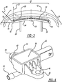
- FIG. 3 is a pictorial view showing the installation position of sensor assembly 14 in accordance with this invention.
- sensor assembly 14 is mounted behind fascia 12 and may also be mounted behind energy absorbing material 23.
- Cross beam 24 extends laterally from the vehicle centerline 26 and is supported by longitudinal beam 28.
- An impact of the front end 11 deforms fascia 12, compressing tube 22 between the fascia and bumper beam 24, thereby generating the pressure signal mentioned previously.
- the pressure based sensor or other compressive or compression sensor
- Front corner areas 19 are defined as the region laterally outboard of cross beam 24 and extending to the surface of front end 11, merging with vehicle front fenders 17. Center section 27 is the front end region inboard of corner areas 19. As mentioned previously, corner areas 19 may also be described as the end, the most-outer end, or the boundaries of the vehicle front end 11.
- a compression-based sensor may also communicate with structures filled with energy absorbing material such as foam or other elastomeric materials. Compression of such materials will generate a pressure pulse which can be detected by the sensor.
- energy absorbing material such as foam or other elastomeric materials. Compression of such materials will generate a pressure pulse which can be detected by the sensor.
- sensor assembly housings 16 and 18 are mounted laterally past the lateral edges of cross beam 24 and, in accordance with this invention, integrally incorporate an acceleration based sensor which may have a sensing axis 30 oriented in various manners.
- a sensing axis 30 oriented oblique to vehicle centerline 26.
- the sensor sensing axis direction 30 can be oriented to be normal to fascia 12 at the sensor housing location, or in other directions such as direction 32 parallel to the vehicle direction of travel and vehicle centerline 26, or laterally in direction 34.
- the acceleration sensor could also be a multi-axis sensor, or more than one sensor could be used with more than one corresponding sense axis.
- FIG. 4 is a pictorial view of sensor assembly housing 16 or 18 (since they may be identical, housings 16 and 18 are described with reference to housing 16).
- housing 16 includes a hollow body section 36, a pair of projecting mounting pads 38 with fastener apertures 40, extending tube connection 20, and an electrical connector 42.
- housing 16 is formed by injection molding of a plastic resin material.
- FIG. 5 is a cross-sectional view through sensor assembly housing 16.
- the illustration shows an internally mounted PC board 44 mounted within hollow body 36.
- PC board 44 has on one surface, acceleration sensor 46 shown mounted on the upper surface of the PC board.
- the lower surface has mounted pressure sensor 48 which is fluidically sealed with the inside of tube 22 and tube connection 20.
- electrical connector 42 includes internal terminals 50 which are electrically connected to PC board 44.
- Acceleration sensor 46 and pressure sensor 48 are preferably integrated types having internal signal processing electronic elements and made as an integrated chip component having electrical connections for wire binding to PC board 44.
- the upper region of hollow body 36 can be potted with sealant or a separate resin cover component can be bonded or fastened to enclose housing 16.
- FIG 6 illustrates graphically a pressure pulse being applied to sensor assembly housing 16.
- the arrows 56 indicate a pressure pulse being conducted through tube 22 into tube connector 20 and acting upon pressure sensor 48.
- Figure 7 illustrates diagrammatically acceleration sensor 46 providing a signal due to acceleration acting on sensor assembly housing 16 designated by arrows 58.
- housing 16 integrates the functions of pressure (or compression) and acceleration based sensors in an integrated package. Since the sensing axis 30 or sensor direction of acceleration sensor 46 is important in the design of the system, mounting pads 38 are affixed in a desired manner with regard to vehicle structures, such as directly to fascia 12, internal brackets, extensions of cross beam 24, or other structure.
- FIG 8 shows diagrammatically the relationship between the sensor system of the invention and other portions of a restraint system controller for the vehicle.
- housing 16 provides a mount for both acceleration sensor 46 and pressure sensor 48 which produce signals sent via signal lines 52 to a restraint system controller 54.
- Controller 54 can provide numerous other safety related functions for the vehicle including the deployment of passive occupant restraint systems such as inflatable restraints, belt pretensioners, and other safety measures.
- Figures 10a and 10b illustrate an alternate sensor arrangement 66 which, like sensor arrangement 60, uses discrete acceleration sensors 62 and a compressive based sensor 64.
- single acceleration sensors 62 are implemented for front corner areas 19.
- Cross beam 24 features compressive based pressure sensor 64.
- pressure sensor 64 utilizes an enclosed tube 22 to conduct a pressure pulse to the pressure sensor.
- Arrangement 66 further illustrates single acceleration sensors 62 at each front corner area 19.
- the acceleration sensors 62 illustrated in Figures 9a, 9b , 10a, and 10b may be oriented with their sensing axes 30 oriented in various directions, including those diagramed in Figure 3 .
- the sensing axes 30 of multiple accelerations sensors 62 may be oriented in differing directions from one another where more than one is used on each front corner area 19.
Landscapes
- Engineering & Computer Science (AREA)
- Mechanical Engineering (AREA)
- Physics & Mathematics (AREA)
- General Physics & Mathematics (AREA)
- Chemical & Material Sciences (AREA)
- Analytical Chemistry (AREA)
- Measuring Fluid Pressure (AREA)
- Body Structure For Vehicles (AREA)
- Force Measurement Appropriate To Specific Purposes (AREA)
Abstract
Description
- This invention relates to a vehicle mounted sensor system and, in particular, to one adapted to be mounted to the front end of a motor vehicle for detecting pedestrian-involved impacts like pedestrian and bicyclists impacts, and activating appropriate impact mitigation countermeasures.
- Motor vehicle collisions with pedestrians and bicyclists are a significant concern. While significant advancements have been made in protecting motor vehicle occupants from injury due to impacts, there remain significant opportunities to reduce injuries, particularly head injuries to pedestrians struck by motor vehicles. Various countermeasure systems have been devised for this purpose and are in use. Hood lifter mechanisms pop the engine compartment hood to an upward displaced position where it can absorb energy as a struck pedestrian hinges about their lower torso and strikes the hood area during an impact. The lifted hood provides energy absorption. Other measures such as external airbags have further been conceived and implemented. In this description, reference to pedestrian impacts is intended to include other types of impacts including those with bicyclists or animals and other low-energy (as compared with striking other vehicles or fixed objects) impacts.
- For any deployable pedestrian impact countermeasure to be operative, some means of detecting the impact is required. Numerous systems are available for detecting such impacts. One approach uses an elongated flexible hollow tube which defines an enclosed volume of gas. Upon an impact, the soft fascia of the vehicle front end is deformed and the sensor tube is compressed, generating a gas pressure in the tube which is transmitted to a pressure sensor, thereby detecting the impact. For these systems to be operative, a supporting structure behind the pressure based sensor is necessary. This enables the necessary compression to occur for generating the pressure pulse. Numerous other sensor technologies may be implemented which measure strain or compression exerted by deformation of the vehicle front end fascia. Other types of low energy impact sensing systems include switch arrays, peizo cable, fiber optic, etc. All such sensing techniques based on compression will be referred herein as compressive or compression sensors.
- A particular design challenge is posed in extending the sensitive area of the vehicle front end to low energy impacts to include the outer corners or edges of the front end (referred in this description also as the end, the most-outer end, or the boundaries of the front end). Typical passenger car and light truck vehicles feature rounded front end corners which creates a glancing or oblique impact if the pedestrian strikes the vehicle in these areas. The glancing impact may not provide the necessary compression for a compression sensor. Moreover, typical vehicle front ends feature an energy absorbing cross beam in the front end needed for meeting low speed impact requirements. The structure of the energy absorbing beam may not extend laterally to these outer front corners. Accordingly, it is often the case that an underlying structure necessary for creating a reaction force to the impact resulting in compression of the sensing system in these outer corner areas is absent.
- In view of the aforementioned, there is a need in the art for improved pedestrian impact system which addresses the previously mentioned shortcomings in prior art systems.
- In any volume produced automotive application, cost concerns are significant. The increased sophistication and capabilities of motor vehicles must be provided in an efficient and low cost manner in order that the features become commercially viable. Accordingly, systems provided to meet the design objectives mentioned above need to be manufacturable and capable of being assembled in a cost effective manner.
- In accordance with the present invention, a pedestrian sensor system is provided incorporating features of compressive and acceleration based sensors. The compressive based system is used in a front center section of the front end where the supporting bumper structure is present. In the outer corner areas, an acceleration based sensor is provided. For efficient packaging and installation considerations, in one embodiment of the present invention, the acceleration and pressure based sensors are conveniently mounted in a unitary package with mounting features so that the acceleration sensors can be properly oriented with regard to the fascia surface. Despite the lack of supporting structure, the acceleration based sensors undergo acceleration as they are impacted and may not necessitate compression to create a sensor output.
- Additional benefits and advantages of the present invention will become apparent to those skilled in the art to which the present invention relates from the subsequent description of the preferred embodiment and the appended claims, taken in conjunction with the accompanying drawings.
-
-
Figure 1 is a front pictorial view of a motor vehicle incorporating a sensor system in accordance with this invention; -
Figure 2 is a pictorial view of the sensor assembly fromFigure 1 ; -
Figure 3 is overhead schematic drawing of the sensor system and one possible relationship with motor vehicle structural components; -
Figure 4 is a pictorial view of the sensor housing in accordance with this invention; -
Figure 5 is a cross-sectional view of the sensor housing shown inFigure 4 ; -
Figure 6 illustrates the sensor housing receiving a pressure pulse signal; -
Figure 7 is a cross-sectional view of the sensor illustrating and sensor receiving an acceleration signal; -
Figure 8 is a schematic view of the electrical connections in the system; -
Figures 9a and 9b are schematic representations of an alternate embodiment of the present invention; and -
Figures 10a and 10b are schematic representations of a further alternate embodiment of the present invention. - With reference to
Figure 1 , arepresentative motor vehicle 10 is shown with itsfront end 11 which includesfront fascia 12,hood 13, andbumper 15, which joinsfront fenders 17 at front boundary (corner)areas 19. In the lower portion offront end 11, which could be behindfront fascia 12 orbumper 15 is providedsensor assembly 14 in accordance with the present invention.Sensor assembly 14 is optimally placed behind the motor vehicle part that receives the best or first contact with a pedestrian during an impact and also high in terms of integration of the components. In the illustrated embodiment,sensor assembly 14 is mounted behindfront fascia 12, but is shown inFigure 1 in broken lines to show its positioning.Sensor assembly 14 is shown pictorially inFigure 2 and includessensor assembly housings housings barbed tube connections 20.Flexible tube 22 extends betweenhousings tube 22 generates a pressure pulse which is detected by internal pressure sensors withinhousings sensor assembly 14 features a compressive sensor of a type using a fluid pressure signal.Figure 1 illustrates an SUVtype motor vehicle 10; however, the invention is equally applicable to a variety of motor vehicle types including sedan-type passenger cars. -
Figure 3 is a pictorial view showing the installation position ofsensor assembly 14 in accordance with this invention. As mentioned above,sensor assembly 14 is mounted behindfascia 12 and may also be mounted behindenergy absorbing material 23.Cross beam 24 extends laterally from thevehicle centerline 26 and is supported bylongitudinal beam 28. An impact of thefront end 11deforms fascia 12, compressingtube 22 between the fascia andbumper beam 24, thereby generating the pressure signal mentioned previously. At the outboardfront corner areas 19 regions of thefront end 11 which extend laterally past cross beam 24 (and also designated as the areas laterally outboard of the dashed-line box inFigure 3 ), the pressure based sensor (or other compressive or compression sensor) lacks backing support for reliable compression oftube 22.Front corner areas 19 are defined as the region laterally outboard ofcross beam 24 and extending to the surface offront end 11, merging withvehicle front fenders 17.Center section 27 is the front end region inboard ofcorner areas 19. As mentioned previously,corner areas 19 may also be described as the end, the most-outer end, or the boundaries of the vehiclefront end 11. - A compression-based sensor may also communicate with structures filled with energy absorbing material such as foam or other elastomeric materials. Compression of such materials will generate a pressure pulse which can be detected by the sensor.
- As shown in
Figure 3 ,sensor assembly housings cross beam 24 and, in accordance with this invention, integrally incorporate an acceleration based sensor which may have asensing axis 30 oriented in various manners. InFigure 3 there is shown asensing axis 30 oriented oblique tovehicle centerline 26. The sensorsensing axis direction 30 can be oriented to be normal tofascia 12 at the sensor housing location, or in other directions such asdirection 32 parallel to the vehicle direction of travel andvehicle centerline 26, or laterally indirection 34. The acceleration sensor could also be a multi-axis sensor, or more than one sensor could be used with more than one corresponding sense axis. -
Figure 4 is a pictorial view ofsensor assembly housing 16 or 18 (since they may be identical,housings housing 16 includes ahollow body section 36, a pair of projecting mountingpads 38 withfastener apertures 40, extendingtube connection 20, and anelectrical connector 42. Conveniently,housing 16 is formed by injection molding of a plastic resin material. -
Figure 5 is a cross-sectional view throughsensor assembly housing 16. The illustration shows an internally mountedPC board 44 mounted withinhollow body 36.PC board 44 has on one surface,acceleration sensor 46 shown mounted on the upper surface of the PC board. The lower surface has mountedpressure sensor 48 which is fluidically sealed with the inside oftube 22 andtube connection 20. It is noted that the gas volume defined by thetube 22 and the connected volumes ofsensor housings electrical connector 42 includesinternal terminals 50 which are electrically connected toPC board 44.Acceleration sensor 46 andpressure sensor 48 are preferably integrated types having internal signal processing electronic elements and made as an integrated chip component having electrical connections for wire binding toPC board 44. The upper region ofhollow body 36 can be potted with sealant or a separate resin cover component can be bonded or fastened to enclosehousing 16. -
Figure 6 illustrates graphically a pressure pulse being applied tosensor assembly housing 16. As shown, thearrows 56 indicate a pressure pulse being conducted throughtube 22 intotube connector 20 and acting uponpressure sensor 48.Figure 7 illustratesdiagrammatically acceleration sensor 46 providing a signal due to acceleration acting onsensor assembly housing 16 designated byarrows 58. Thus,housing 16 integrates the functions of pressure (or compression) and acceleration based sensors in an integrated package. Since the sensingaxis 30 or sensor direction ofacceleration sensor 46 is important in the design of the system, mountingpads 38 are affixed in a desired manner with regard to vehicle structures, such as directly tofascia 12, internal brackets, extensions ofcross beam 24, or other structure. -
Figure 8 shows diagrammatically the relationship between the sensor system of the invention and other portions of a restraint system controller for the vehicle. As shown,housing 16 provides a mount for bothacceleration sensor 46 andpressure sensor 48 which produce signals sent viasignal lines 52 to arestraint system controller 54.Controller 54 can provide numerous other safety related functions for the vehicle including the deployment of passive occupant restraint systems such as inflatable restraints, belt pretensioners, and other safety measures. -
Figures 9a and 9b illustrate an alternate embodiment of asensor arrangement 60 in accordance with the present invention. As illustrated,sensor arrangement 60 does not utilize the integrated acceleration and pressure sensors provided bysensor assembly 14. Instead,separate acceleration sensors 62 and pressure (or another compressive or compression)sensors 64 are used.Figure 9a illustrates schematically that apressure sensor 64 is used to measure impacts acting oncross beam 24, whereasseparate acceleration sensors 62 are provided alongfascia 12 infront corner areas 19. As shown, more than oneacceleration sensor 62 may be provided in each offront corner areas 19. One ormore acceleration sensors 62 could be mounted to crossbeam 24 to measure acceleration of that component, providing measurement of higher severity impacts. The implementation ofsensor arrangement 60 provides many of the advantages of the system previously described in that it provides compressive based sensor in the center area of front and 11 while using acceleration-based pedestrian impact sensing atfront corner areas 19.Sensor arrangement 60 can utilize anenclosed volume 68 behindfascia 12 provided byenergy absorbing material 23. If such anenclosed volume 68 can be formed it may be a means of transmitting a pressure pulse topressure sensor 64, eliminating the need for aseparate tube 22. -
Figures 10a and 10b illustrate an alternate sensor arrangement 66 which, likesensor arrangement 60, usesdiscrete acceleration sensors 62 and a compressive basedsensor 64. In this instance,single acceleration sensors 62 are implemented forfront corner areas 19.Cross beam 24 features compressive basedpressure sensor 64. In this case,pressure sensor 64 utilizes anenclosed tube 22 to conduct a pressure pulse to the pressure sensor. Arrangement 66 further illustratessingle acceleration sensors 62 at eachfront corner area 19. Theacceleration sensors 62 illustrated inFigures 9a, 9b ,10a, and 10b may be oriented with theirsensing axes 30 oriented in various directions, including those diagramed inFigure 3 . Moreover, the sensing axes 30 ofmultiple accelerations sensors 62 may be oriented in differing directions from one another where more than one is used on eachfront corner area 19. - For implementation of compressive based sensors which do not use gas pressure for sensing,
tube 22 may be replaced by a compressive element or an array of compressive elements arranged along a strip extending across the vehicle in the position shown for the tube. - While the above description constitutes the preferred embodiment of the present invention, it will be appreciated that the invention is susceptible to modification, variation, and change without departing from the proper scope and fair meaning of the accompanying claims.
The following clauses, which form part of the description, provide general expressions of the disclosure herein. - A1. A low-energy impact sensor assembly for mounting to the front end of a motor vehicle for detecting a low energy impact such as a pedestrian impact for deploying an impact countermeasure, comprising;
an acceleration sensor in a housing with a mounting feature for affixing the housing to the motor vehicle at a predetermined position, the acceleration sensor having at least one sensing axis oriented in a predetermined orientation with respect to the motor vehicle, the acceleration sensor acting to detect the impact due to acceleration of the acceleration sensor, and
a compression sensor acting to detect the impact by compression of a component of the motor vehicle, the compression sensor and the acceleration sensor acting together to detect the impact. - A2. A low-energy impact sensor assembly according to clause A1 further comprising the compression sensor mounted to the housing.
- A3. A low-energy impact sensor assembly according to clause A1 further comprising the compression sensor in the form of a pressure sensor communicating with an enclosed volume of a gas, wherein the pressure sensor detects the impact when the enclosed volume is decreased by compression during the impact.
- A4. A low-energy impact sensor assembly according to clause A3 further comprising the enclosed volume defined by a deformable pressure tube.
- A5. A low-energy impact sensor assembly according to clause A3 further comprising, a pair of the housing assemblies connected with opposing ends of the pressure tube.
- A6. A low-energy impact sensor according to clause A5 further comprising,
a first of the pair of housing assemblies mounted to a front end of the vehicle at a left-side front boundary area of the front end and a second of the pair of housing assemblies mounted to a right-side front boundary area of the front end. - A7. A low-energy impact sensor assembly according to clause A4 further comprising, wherein the housing assembly and the pressure tube are mounted behind a fascia covering at least a portion of the front end.
- A8. A low-energy impact sensor assembly according to clause A7 further comprising, the tube mounted between the fascia and a bumper beam.
- A9. A low-energy impact sensor assembly according to clause A1 further comprising, wherein the direction of the at least one sensing axis is oriented in a direction parallel to the longitudinal axis of the motor vehicle.
- A10. A low-energy impact sensor assembly according to clause A1 further comprising, wherein the direction of the at least one sensing axis is oriented in a direction oblique to the longitudinal axis of the motor vehicle.
- A11. A low-energy impact sensor assembly according to clause A1 further comprising, wherein the direction of the at least one sensing axis is oriented in a direction perpendicular to the longitudinal axis of the motor vehicle.
- A12. A low-energy impact sensor assembly according to clause A3 further comprising, the compression sensor mounted to the housing, the housing forming a hollow body having a PC board mounted therein, and wherein the acceleration sensor is mounted to one surface of the PC board and the pressure sensor is mounted to an opposing surface of the PC board.
- A13. A low-energy impact sensor assembly according to clause A12 further comprising the housing forming an internal volume communicating the pressure tube with the pressure sensor whereby compression of the tube generates a pressure acting on the pressure sensor.
- A14. A low-energy impact sensor system having the impact sensor assembly according to clause A1 further comprising a restraint system controller receiving signals from at least one of the pressure sensor and the acceleration sensor to deploy the countermeasures based on at least one of a pressure signal from the pressure sensor and an acceleration signal from the acceleration sensor.
- A15. The low-energy impact sensor system according to clause A14 further comprising the enclosed volume defined by a pressure tube extending across the cross beam.
- A16. The low-energy impact sensor system according to clause A14 further comprising the enclosed volume defined by an energy absorbing member positioned between the front fascia and a cross beam of the vehicle.
- A17. The low-energy impact sensor system according to clause A16 further comprising at least a pair of the acceleration sensors mounted to or adjacent to the front fascia at each of the front boundary areas.
- A18. The low-energy impact sensor system according to clause A14 further comprising an acceleration sensor mounted to the cross beam.
- A19. A low-energy impact sensor assembly according to clause A14 further comprising, wherein the direction of the sensing axis is oriented in a direction parallel to the longitudinal axis of the motor vehicle.
- A20. A low-energy impact sensor assembly according to clause A14 further comprising, wherein the direction of the sensing axis is oriented in a direction oblique to the longitudinal axis of the motor vehicle.
- A21. A low-energy impact sensor assembly according to Clause A14further comprising, wherein the direction of the sensing axis is oriented in a direction perpendicular to the longitudinal axis of the motor vehicle.
Claims (15)
- A motor vehicle (10) comprising an impact sensor assembly (14) mounted to the front end (11) of the motor vehicle (10) for detecting a low energy impact such as a pedestrian impact for deploying an impact countermeasure, the sensor assembly (14) comprising;
an acceleration sensor (46, 62) in a housing assembly (16, 18) affixed to the motor vehicle (10) at a predetermined position, the acceleration sensor (46, 62) having at least one sensing axis (30) oriented in a predetermined orientation with respect to the motor vehicle (10), the acceleration sensor (46, 62) acting to detect the impact due to acceleration of the acceleration sensor (46, 62), and
a compression sensor (48, 64) acting to detect the impact by compression of a component (22, 23) of the motor vehicle (10);
characterised in that said compression sensor (48, 64) is configured to detect the impact by compression of said component (22, 23) in a front center section (27) of said front end (11) of the motor vehicle (10), and said acceleration sensor (46, 62) is provided in an outer corner (19) area of said front end (11). - A motor vehicle (10) according to Claim 1, wherein the compression sensor (48) is mounted to the housing (16, 18).
- A motor vehicle (10) according to Claim 1 or Claim 2, wherein the compression sensor is provided in the form of a pressure sensor (48) communicating with an enclosed volume of a gas, the pressure sensor (48) being configured to detect the impact when the enclosed volume is decreased by compression during the impact.
- A motor vehicle (10) according to Claim 3 wherein the housing (16, 18) assembly forms a hollow body (36) having a PC board (44) mounted therein, the acceleration sensor (46) being mounted to one surface of the PC board (44) and the pressure sensor (48) being mounted to an opposing surface of the PC board (44).
- A motor vehicle (10) according to Claim 3 or Claim 4, wherein the enclosed volume is defined by a deformable pressure tube (22) extending across a cross beam (24) of the motor vehicle (10).
- A motor vehicle (10) according to Claim 5, wherein the housing (16,18) forms an internal volume communicating the pressure tube (22) with the pressure sensor (48), whereby compression of the tube (22) generates a pressure acting on the pressure sensor (48).
- A motor vehicle (10) according to Claim 5 or Claim 6 comprising, a pair of said housing assemblies (16, 18), each housing assembly (16, 18) having a respective said acceleration sensor (46) and being connected with a respective end of the pressure tube (22).
- A motor vehicle (10) according to Claim 7 wherein one of said housing assemblies (16) is mounted to a front end (11) of the vehicle (10) at a left-side front corner area (19) of the front end (11), and the other housing assembly (18) is mounted to a right-side front corner area (19) of the front end (11).
- A motor vehicle (10) according to any one of Claims 5 to 8, wherein the or each housing assembly (16, 18) and the pressure tube (22) are mounted behind a fascia (12) covering at least a portion of the front end (11).
- A motor vehicle (10) according to Claim 8, wherein the pressure tube (22) is mounted between the fascia (12) and a cross beam (24) of the motor vehicle (10).
- A motor vehicle (10) according to any one of Claims 1 to 4, wherein the enclosed volume (68) is defined by an energy absorbing member (23) positioned between the front fascia (12) and a cross beam (24) of the motor vehicle (10).
- A motor vehicle (10) according to any preceding claim, wherein the direction of the at least one sensing axis (30) is oriented in a direction parallel to the longitudinal axis (26) of the motor vehicle (10).
- A motor vehicle (10) according to any one of Claims 1 to 11, wherein the direction of the at least one sensing axis (30) is oriented in a direction oblique to the longitudinal axis (26) of the motor vehicle (10).
- A motor vehicle (10) according to any one of Claims 1 to 11, wherein the direction of the at least one sensing axis (30) is oriented in a direction perpendicular to the longitudinal axis (26) of the motor vehicle (10).
- A motor vehicle (10) according to any preceding claim and further comprising a restraint system controller (54) receiving signals from at least one of the pressure sensor (48) and the acceleration sensor (46) to deploy the countermeasures based on at least one of a pressure signal from the pressure sensor (48) and an acceleration signal from the acceleration sensor (46).
Applications Claiming Priority (3)
| Application Number | Priority Date | Filing Date | Title |
|---|---|---|---|
| US13/585,367 US8972116B2 (en) | 2012-08-14 | 2012-08-14 | Pressure and acceleration based pedestrian impact sensor assembly for motor vehicles |
| PCT/US2013/054631 WO2014028425A1 (en) | 2012-08-14 | 2013-08-13 | Pressure and acceleration based pedestrian impact sensor assembly for motor vehicles |
| EP13829572.0A EP2885159B1 (en) | 2012-08-14 | 2013-08-13 | Pressure and acceleration based pedestrian impact sensor assembly for motor vehicles |
Related Parent Applications (2)
| Application Number | Title | Priority Date | Filing Date |
|---|---|---|---|
| EP13829572.0A Division-Into EP2885159B1 (en) | 2012-08-14 | 2013-08-13 | Pressure and acceleration based pedestrian impact sensor assembly for motor vehicles |
| EP13829572.0A Division EP2885159B1 (en) | 2012-08-14 | 2013-08-13 | Pressure and acceleration based pedestrian impact sensor assembly for motor vehicles |
Publications (1)
| Publication Number | Publication Date |
|---|---|
| EP3424778A1 true EP3424778A1 (en) | 2019-01-09 |
Family
ID=50100630
Family Applications (2)
| Application Number | Title | Priority Date | Filing Date |
|---|---|---|---|
| EP18187136.9A Withdrawn EP3424778A1 (en) | 2012-08-14 | 2013-08-13 | Pressure and acceleration based pedestrian impact sensor assembly for motor vehicles |
| EP13829572.0A Active EP2885159B1 (en) | 2012-08-14 | 2013-08-13 | Pressure and acceleration based pedestrian impact sensor assembly for motor vehicles |
Family Applications After (1)
| Application Number | Title | Priority Date | Filing Date |
|---|---|---|---|
| EP13829572.0A Active EP2885159B1 (en) | 2012-08-14 | 2013-08-13 | Pressure and acceleration based pedestrian impact sensor assembly for motor vehicles |
Country Status (4)
| Country | Link |
|---|---|
| US (1) | US8972116B2 (en) |
| EP (2) | EP3424778A1 (en) |
| JP (1) | JP6086563B2 (en) |
| WO (1) | WO2014028425A1 (en) |
Families Citing this family (23)
| Publication number | Priority date | Publication date | Assignee | Title |
|---|---|---|---|---|
| DE102013004561B4 (en) * | 2013-03-15 | 2017-05-04 | Infineon Technologies Ag | A DEVICE FOR RECOGNIZING A POWDER EFFECT AND A METHOD FOR RECOGNIZING A POWDER IMPACT |
| DE102013205490A1 (en) * | 2013-03-27 | 2014-10-02 | Bayerische Motoren Werke Aktiengesellschaft | Bumper assembly for a passenger car and passenger cars with such a bumper assembly |
| US9221414B2 (en) * | 2014-03-31 | 2015-12-29 | Ford Global Technologies, Llc | Impact tubing for pedestrian protection sensor for automotive vehicle |
| LU92625B1 (en) * | 2014-12-24 | 2016-06-27 | Iee Sarl Eng Sa | Crash detection system |
| US10451728B2 (en) | 2015-09-30 | 2019-10-22 | Veoneer Us, Inc. | Apparatus and method for attenuating close-range radar signals with balancing for dual-frequency difference in radar signals in an automotive radar sensor |
| USD844518S1 (en) * | 2016-07-20 | 2019-04-02 | Jaguar Land Rover Limited | Front end of a vehicle |
| US10741955B2 (en) * | 2016-09-29 | 2020-08-11 | Veoneer Us, Inc. | Sensor assembly and method for assembling a sensor connector assembly |
| KR102637239B1 (en) * | 2017-02-27 | 2024-02-19 | 현대모비스 주식회사 | Pressure sensing apparatus for vehicle |
| USD837702S1 (en) | 2017-04-28 | 2019-01-08 | Oshkosh Defense, Llc | Vehicle hood |
| USD876999S1 (en) * | 2017-05-17 | 2020-03-03 | Jaguar Land Rover Limited | Vehicle front bumper upper |
| USD856212S1 (en) * | 2017-08-31 | 2019-08-13 | Jaguar Land Rover Limited | Rear bumper for a vehicle |
| DE102017218945A1 (en) * | 2017-10-24 | 2019-04-25 | Robert Bosch Gmbh | Pressure sensor for a personal protection system of a vehicle |
| CN108032303A (en) * | 2018-01-03 | 2018-05-15 | 杭州艾米机器人有限公司 | The collision detection mechanism and robot of robot |
| US10451645B2 (en) | 2018-03-12 | 2019-10-22 | Veoneer Us Inc. | Remote sensor construction via integrated vacuum manufacture process |
| CN108515932A (en) * | 2018-05-09 | 2018-09-11 | 蚌埠市华威电子科技有限公司 | A kind of bumper radar probe sensor |
| DE102018216784B4 (en) * | 2018-09-28 | 2025-08-07 | Continental Autonomous Mobility Germany GmbH | Sensor arrangement for a vehicle and vehicle |
| JP7439127B2 (en) * | 2019-04-08 | 2024-02-27 | ツェットエフ、フリードリッヒスハーフェン、アクチエンゲゼルシャフト | Low-impact detection for autonomous vehicles |
| CN110501641A (en) * | 2019-08-23 | 2019-11-26 | Oppo(重庆)智能科技有限公司 | The test device of electronic equipment |
| KR102642568B1 (en) * | 2019-09-27 | 2024-02-29 | 현대모비스 주식회사 | Pedestrians impact sensing device |
| EP3835137B1 (en) | 2019-12-10 | 2024-02-21 | Veoneer Sweden Safety Systems AB | Impact sensor assembly |
| EP3835747B1 (en) | 2019-12-10 | 2025-03-05 | Veoneer Sweden Safety Systems AB | Sensor assembly |
| RU199808U1 (en) * | 2020-03-17 | 2020-09-21 | Общество с ограниченной ответственностью "Объединенный инженерный центр" (ООО "ОИЦ") | FRONTAL RADAR INSTALLATION SYSTEM FOR MEDIUM-CAPACITY TRUCKS |
| USD1048983S1 (en) * | 2022-04-19 | 2024-10-29 | GM Global Technology Operations LLC | Vehicle front fascia plate |
Citations (5)
| Publication number | Priority date | Publication date | Assignee | Title |
|---|---|---|---|---|
| US20020103590A1 (en) * | 2001-01-31 | 2002-08-01 | Schondorf Steven Yellin | Restraint and fuel system cutoff control module |
| WO2003082639A1 (en) * | 2002-03-28 | 2003-10-09 | Autoliv Development Ab | An impact detector system |
| DE102008008746A1 (en) * | 2008-02-12 | 2008-08-21 | Daimler Ag | Operator protection system of motor vehicle, has operator protection device and activation device for activating operator protection device, where activation device has two sensors that are spatially separated from each other |
| DE102010018400A1 (en) * | 2010-04-27 | 2010-10-28 | Daimler Ag | Sensor system device for determination of pedestrian impact at vehicle, particularly at bumper unit, has sensor arranged in vehicle, where sensor is pressure sensor |
| EP2628646A1 (en) * | 2012-02-17 | 2013-08-21 | Continental Automotive GmbH | Impact sensor system with at least one pressure sensor |
Family Cites Families (16)
| Publication number | Priority date | Publication date | Assignee | Title |
|---|---|---|---|---|
| US7098778B1 (en) | 1999-09-27 | 2006-08-29 | Autoliv Asp, Inc. | Impact sensor assembly and method of attaching same to a vehicle |
| US6929282B1 (en) | 1999-09-27 | 2005-08-16 | Autoliv Asp, Inc. | Vehicle impact sensing system |
| JP2004276885A (en) * | 2003-03-19 | 2004-10-07 | Denso Corp | Vehicle pedestrian protection system |
| JP4161258B2 (en) * | 2003-04-15 | 2008-10-08 | 株式会社デンソー | Vehicle collision object discrimination device |
| JP4534856B2 (en) | 2005-04-27 | 2010-09-01 | 株式会社デンソー | Side door collision detection system |
| US7303041B2 (en) | 2005-08-22 | 2007-12-04 | Key Safety Systems, Inc. | Vehicle soft impact detection |
| JP5013157B2 (en) * | 2005-10-28 | 2012-08-29 | 株式会社デンソー | Vehicle collision detection device |
| JP4726650B2 (en) * | 2006-02-24 | 2011-07-20 | 本田技研工業株式会社 | Vehicle sensor module |
| DE102006038151B4 (en) * | 2006-08-16 | 2020-06-10 | Robert Bosch Gmbh | Method and device for controlling personal protection devices |
| JP5077639B2 (en) * | 2006-12-11 | 2012-11-21 | 株式会社デンソー | Pedestrian collision detection device and pedestrian protection system |
| JP4905372B2 (en) * | 2007-06-27 | 2012-03-28 | 日産自動車株式会社 | Mounting structure of impact sensor for vehicle |
| JP5206857B2 (en) * | 2007-06-27 | 2013-06-12 | 日産自動車株式会社 | Mounting structure of impact sensor for vehicle |
| JP4466690B2 (en) | 2007-07-17 | 2010-05-26 | 株式会社デンソー | Collision detection device |
| JP4513833B2 (en) | 2007-07-17 | 2010-07-28 | 株式会社デンソー | Vehicle collision detection device |
| US8374751B2 (en) * | 2008-06-06 | 2013-02-12 | Chrysler Group Llc | Automotive impact sensing system |
| JP4980300B2 (en) * | 2008-06-12 | 2012-07-18 | 株式会社デンソー | Vehicle collision determination device |
-
2012
- 2012-08-14 US US13/585,367 patent/US8972116B2/en active Active
-
2013
- 2013-08-13 JP JP2015527523A patent/JP6086563B2/en active Active
- 2013-08-13 WO PCT/US2013/054631 patent/WO2014028425A1/en not_active Ceased
- 2013-08-13 EP EP18187136.9A patent/EP3424778A1/en not_active Withdrawn
- 2013-08-13 EP EP13829572.0A patent/EP2885159B1/en active Active
Patent Citations (5)
| Publication number | Priority date | Publication date | Assignee | Title |
|---|---|---|---|---|
| US20020103590A1 (en) * | 2001-01-31 | 2002-08-01 | Schondorf Steven Yellin | Restraint and fuel system cutoff control module |
| WO2003082639A1 (en) * | 2002-03-28 | 2003-10-09 | Autoliv Development Ab | An impact detector system |
| DE102008008746A1 (en) * | 2008-02-12 | 2008-08-21 | Daimler Ag | Operator protection system of motor vehicle, has operator protection device and activation device for activating operator protection device, where activation device has two sensors that are spatially separated from each other |
| DE102010018400A1 (en) * | 2010-04-27 | 2010-10-28 | Daimler Ag | Sensor system device for determination of pedestrian impact at vehicle, particularly at bumper unit, has sensor arranged in vehicle, where sensor is pressure sensor |
| EP2628646A1 (en) * | 2012-02-17 | 2013-08-21 | Continental Automotive GmbH | Impact sensor system with at least one pressure sensor |
Also Published As
| Publication number | Publication date |
|---|---|
| WO2014028425A8 (en) | 2015-03-19 |
| US20140052341A1 (en) | 2014-02-20 |
| EP2885159A1 (en) | 2015-06-24 |
| US8972116B2 (en) | 2015-03-03 |
| WO2014028425A1 (en) | 2014-02-20 |
| JP6086563B2 (en) | 2017-03-01 |
| EP2885159B1 (en) | 2021-03-10 |
| EP2885159A4 (en) | 2016-05-11 |
| JP2015536855A (en) | 2015-12-24 |
Similar Documents
| Publication | Publication Date | Title |
|---|---|---|
| US8972116B2 (en) | Pressure and acceleration based pedestrian impact sensor assembly for motor vehicles | |
| JP4264844B2 (en) | Vehicle collision detection device | |
| US9994184B2 (en) | Vehicle side airbag with secondary chamber | |
| KR101020549B1 (en) | Vehicle exterior airbag device | |
| US9221414B2 (en) | Impact tubing for pedestrian protection sensor for automotive vehicle | |
| JP4749643B2 (en) | Impact sensor assembly and method of attaching the assembly to a vehicle | |
| EP2969664B1 (en) | Compressive sensor packaging techniques | |
| US7500394B2 (en) | Fastener integrated sensor | |
| US20180361978A1 (en) | Vehicle airbag | |
| CN108082084B (en) | Deployable device mounted to a vehicle frame | |
| KR102637239B1 (en) | Pressure sensing apparatus for vehicle | |
| US20190054957A1 (en) | Vehicle frame mounted deployable metal bag to mitigate side impact crash intrusions | |
| US7258191B1 (en) | Air bag system incorporated into motor vehicle bumper | |
| KR100760310B1 (en) | Automobile airbag system using stress wave sensor and its operation method | |
| JP2005238990A (en) | Accelerometer mounting structure | |
| US20170021790A1 (en) | LED Crush Sensor | |
| US8538672B2 (en) | 2D-coil collision sensor system | |
| JP4307946B2 (en) | Bumper with built-in airbag | |
| KR100503297B1 (en) | Side air bag | |
| CN101535091B (en) | Crash Safety Control | |
| CA2638886A1 (en) | Air bag system incorporated into motor vehicle bumper | |
| KR101515475B1 (en) | Car body combine with Sensor Module for Air bag | |
| KR20140005177U (en) | Air Bag Sensor Module Installed by Adhesive Method | |
| WO2016180761A1 (en) | Pressure-responsive sensor unit | |
| KR100590969B1 (en) | Automotive Airbag Systems |
Legal Events
| Date | Code | Title | Description |
|---|---|---|---|
| PUAI | Public reference made under article 153(3) epc to a published international application that has entered the european phase |
Free format text: ORIGINAL CODE: 0009012 |
|
| AC | Divisional application: reference to earlier application |
Ref document number: 2885159 Country of ref document: EP Kind code of ref document: P |
|
| AK | Designated contracting states |
Kind code of ref document: A1 Designated state(s): AL AT BE BG CH CY CZ DE DK EE ES FI FR GB GR HR HU IE IS IT LI LT LU LV MC MK MT NL NO PL PT RO RS SE SI SK SM TR |
|
| RIN1 | Information on inventor provided before grant (corrected) |
Inventor name: LEACH, WILLIAM, M. Inventor name: PIETZSCH, SYLVIA Inventor name: CELIK, MUSTAFA, CUMA Inventor name: HOFELSAUER, HERBERT Inventor name: FORWERCK, JOSHUA |
|
| RAP1 | Party data changed (applicant data changed or rights of an application transferred) |
Owner name: VEONEER US, INC. |
|
| RIN1 | Information on inventor provided before grant (corrected) |
Inventor name: PIETZSCH, SYLVIA Inventor name: LEACH, WILLIAM, M. Inventor name: FORWERCK, JOSHUA Inventor name: HOFELSAUER, HERBERT Inventor name: CELIK, MUSTAFA, CUMA |
|
| STAA | Information on the status of an ep patent application or granted ep patent |
Free format text: STATUS: THE APPLICATION IS DEEMED TO BE WITHDRAWN |
|
| 18D | Application deemed to be withdrawn |
Effective date: 20190710 |