EP3424769A1 - Control method, mobile apparatus, brake lever device and braking device - Google Patents
Control method, mobile apparatus, brake lever device and braking device Download PDFInfo
- Publication number
- EP3424769A1 EP3424769A1 EP17773329.2A EP17773329A EP3424769A1 EP 3424769 A1 EP3424769 A1 EP 3424769A1 EP 17773329 A EP17773329 A EP 17773329A EP 3424769 A1 EP3424769 A1 EP 3424769A1
- Authority
- EP
- European Patent Office
- Prior art keywords
- braking
- parameter
- course
- strength
- zero
- Prior art date
- Legal status (The legal status is an assumption and is not a legal conclusion. Google has not performed a legal analysis and makes no representation as to the accuracy of the status listed.)
- Granted
Links
Images





Classifications
-
- B—PERFORMING OPERATIONS; TRANSPORTING
- B62—LAND VEHICLES FOR TRAVELLING OTHERWISE THAN ON RAILS
- B62L—BRAKES SPECIALLY ADAPTED FOR CYCLES
- B62L3/00—Brake-actuating mechanisms; Arrangements thereof
- B62L3/02—Brake-actuating mechanisms; Arrangements thereof for control by a hand lever
-
- B—PERFORMING OPERATIONS; TRANSPORTING
- B60—VEHICLES IN GENERAL
- B60L—PROPULSION OF ELECTRICALLY-PROPELLED VEHICLES; SUPPLYING ELECTRIC POWER FOR AUXILIARY EQUIPMENT OF ELECTRICALLY-PROPELLED VEHICLES; ELECTRODYNAMIC BRAKE SYSTEMS FOR VEHICLES IN GENERAL; MAGNETIC SUSPENSION OR LEVITATION FOR VEHICLES; MONITORING OPERATING VARIABLES OF ELECTRICALLY-PROPELLED VEHICLES; ELECTRIC SAFETY DEVICES FOR ELECTRICALLY-PROPELLED VEHICLES
- B60L50/00—Electric propulsion with power supplied within the vehicle
- B60L50/20—Electric propulsion with power supplied within the vehicle using propulsion power generated by humans or animals
-
- B—PERFORMING OPERATIONS; TRANSPORTING
- B60—VEHICLES IN GENERAL
- B60L—PROPULSION OF ELECTRICALLY-PROPELLED VEHICLES; SUPPLYING ELECTRIC POWER FOR AUXILIARY EQUIPMENT OF ELECTRICALLY-PROPELLED VEHICLES; ELECTRODYNAMIC BRAKE SYSTEMS FOR VEHICLES IN GENERAL; MAGNETIC SUSPENSION OR LEVITATION FOR VEHICLES; MONITORING OPERATING VARIABLES OF ELECTRICALLY-PROPELLED VEHICLES; ELECTRIC SAFETY DEVICES FOR ELECTRICALLY-PROPELLED VEHICLES
- B60L7/00—Electrodynamic brake systems for vehicles in general
- B60L7/003—Dynamic electric braking by short circuiting the motor
-
- B—PERFORMING OPERATIONS; TRANSPORTING
- B60—VEHICLES IN GENERAL
- B60L—PROPULSION OF ELECTRICALLY-PROPELLED VEHICLES; SUPPLYING ELECTRIC POWER FOR AUXILIARY EQUIPMENT OF ELECTRICALLY-PROPELLED VEHICLES; ELECTRODYNAMIC BRAKE SYSTEMS FOR VEHICLES IN GENERAL; MAGNETIC SUSPENSION OR LEVITATION FOR VEHICLES; MONITORING OPERATING VARIABLES OF ELECTRICALLY-PROPELLED VEHICLES; ELECTRIC SAFETY DEVICES FOR ELECTRICALLY-PROPELLED VEHICLES
- B60L7/00—Electrodynamic brake systems for vehicles in general
- B60L7/24—Electrodynamic brake systems for vehicles in general with additional mechanical or electromagnetic braking
- B60L7/26—Controlling the braking effect
-
- B—PERFORMING OPERATIONS; TRANSPORTING
- B60—VEHICLES IN GENERAL
- B60T—VEHICLE BRAKE CONTROL SYSTEMS OR PARTS THEREOF; BRAKE CONTROL SYSTEMS OR PARTS THEREOF, IN GENERAL; ARRANGEMENT OF BRAKING ELEMENTS ON VEHICLES IN GENERAL; PORTABLE DEVICES FOR PREVENTING UNWANTED MOVEMENT OF VEHICLES; VEHICLE MODIFICATIONS TO FACILITATE COOLING OF BRAKES
- B60T7/00—Brake-action initiating means
- B60T7/02—Brake-action initiating means for personal initiation
- B60T7/08—Brake-action initiating means for personal initiation hand actuated
- B60T7/085—Brake-action initiating means for personal initiation hand actuated by electrical means, e.g. travel, force sensors
-
- B—PERFORMING OPERATIONS; TRANSPORTING
- B60—VEHICLES IN GENERAL
- B60T—VEHICLE BRAKE CONTROL SYSTEMS OR PARTS THEREOF; BRAKE CONTROL SYSTEMS OR PARTS THEREOF, IN GENERAL; ARRANGEMENT OF BRAKING ELEMENTS ON VEHICLES IN GENERAL; PORTABLE DEVICES FOR PREVENTING UNWANTED MOVEMENT OF VEHICLES; VEHICLE MODIFICATIONS TO FACILITATE COOLING OF BRAKES
- B60T8/00—Arrangements for adjusting wheel-braking force to meet varying vehicular or ground-surface conditions, e.g. limiting or varying distribution of braking force
- B60T8/17—Using electrical or electronic regulation means to control braking
- B60T8/1701—Braking or traction control means specially adapted for particular types of vehicles
- B60T8/1706—Braking or traction control means specially adapted for particular types of vehicles for single-track vehicles, e.g. motorcycles
-
- B—PERFORMING OPERATIONS; TRANSPORTING
- B62—LAND VEHICLES FOR TRAVELLING OTHERWISE THAN ON RAILS
- B62K—CYCLES; CYCLE FRAMES; CYCLE STEERING DEVICES; RIDER-OPERATED TERMINAL CONTROLS SPECIALLY ADAPTED FOR CYCLES; CYCLE AXLE SUSPENSIONS; CYCLE SIDECARS, FORECARS, OR THE LIKE
- B62K11/00—Motorcycles, engine-assisted cycles or motor scooters with one or two wheels
- B62K11/14—Handlebar constructions, or arrangements of controls thereon, specially adapted thereto
-
- B—PERFORMING OPERATIONS; TRANSPORTING
- B62—LAND VEHICLES FOR TRAVELLING OTHERWISE THAN ON RAILS
- B62K—CYCLES; CYCLE FRAMES; CYCLE STEERING DEVICES; RIDER-OPERATED TERMINAL CONTROLS SPECIALLY ADAPTED FOR CYCLES; CYCLE AXLE SUSPENSIONS; CYCLE SIDECARS, FORECARS, OR THE LIKE
- B62K23/00—Rider-operated controls specially adapted for cycles, i.e. means for initiating control operations, e.g. levers, grips
- B62K23/02—Rider-operated controls specially adapted for cycles, i.e. means for initiating control operations, e.g. levers, grips hand actuated
-
- B—PERFORMING OPERATIONS; TRANSPORTING
- B62—LAND VEHICLES FOR TRAVELLING OTHERWISE THAN ON RAILS
- B62K—CYCLES; CYCLE FRAMES; CYCLE STEERING DEVICES; RIDER-OPERATED TERMINAL CONTROLS SPECIALLY ADAPTED FOR CYCLES; CYCLE AXLE SUSPENSIONS; CYCLE SIDECARS, FORECARS, OR THE LIKE
- B62K23/00—Rider-operated controls specially adapted for cycles, i.e. means for initiating control operations, e.g. levers, grips
- B62K23/02—Rider-operated controls specially adapted for cycles, i.e. means for initiating control operations, e.g. levers, grips hand actuated
- B62K23/06—Levers
-
- B—PERFORMING OPERATIONS; TRANSPORTING
- B60—VEHICLES IN GENERAL
- B60L—PROPULSION OF ELECTRICALLY-PROPELLED VEHICLES; SUPPLYING ELECTRIC POWER FOR AUXILIARY EQUIPMENT OF ELECTRICALLY-PROPELLED VEHICLES; ELECTRODYNAMIC BRAKE SYSTEMS FOR VEHICLES IN GENERAL; MAGNETIC SUSPENSION OR LEVITATION FOR VEHICLES; MONITORING OPERATING VARIABLES OF ELECTRICALLY-PROPELLED VEHICLES; ELECTRIC SAFETY DEVICES FOR ELECTRICALLY-PROPELLED VEHICLES
- B60L2200/00—Type of vehicles
- B60L2200/12—Bikes
-
- B—PERFORMING OPERATIONS; TRANSPORTING
- B60—VEHICLES IN GENERAL
- B60L—PROPULSION OF ELECTRICALLY-PROPELLED VEHICLES; SUPPLYING ELECTRIC POWER FOR AUXILIARY EQUIPMENT OF ELECTRICALLY-PROPELLED VEHICLES; ELECTRODYNAMIC BRAKE SYSTEMS FOR VEHICLES IN GENERAL; MAGNETIC SUSPENSION OR LEVITATION FOR VEHICLES; MONITORING OPERATING VARIABLES OF ELECTRICALLY-PROPELLED VEHICLES; ELECTRIC SAFETY DEVICES FOR ELECTRICALLY-PROPELLED VEHICLES
- B60L2250/00—Driver interactions
- B60L2250/24—Driver interactions by lever actuation
-
- B—PERFORMING OPERATIONS; TRANSPORTING
- B60—VEHICLES IN GENERAL
- B60T—VEHICLE BRAKE CONTROL SYSTEMS OR PARTS THEREOF; BRAKE CONTROL SYSTEMS OR PARTS THEREOF, IN GENERAL; ARRANGEMENT OF BRAKING ELEMENTS ON VEHICLES IN GENERAL; PORTABLE DEVICES FOR PREVENTING UNWANTED MOVEMENT OF VEHICLES; VEHICLE MODIFICATIONS TO FACILITATE COOLING OF BRAKES
- B60T2220/00—Monitoring, detecting driver behaviour; Signalling thereof; Counteracting thereof
- B60T2220/04—Pedal travel sensor, stroke sensor; Sensing brake request
Definitions
- the present disclosure relates to control technology, and in particular to a controlling method, mobile equipment, a braking crank device, and a braking device.
- An electric car finds wide use due to environment friendliness and convenience thereof.
- electric cars such as an electric bicycle, an electric tricycle, an electric four-wheeler, etc.
- Braking performance of an electric car is a key factor considered by a user. Good braking performance may guarantee user safety.
- An existing electric car brakes as follows. When it is detected during a ride that a braking crank has been pressed, power supply of a motor may be cut off. In this case, braking is implemented completely by a mechanical structure. Such a braking mode provides a weak braking strength, which leads to a long braking distance. In this case, a dangerous accident tends to happen.
- a conventional electric braking crank limited by an internal structure thereof, may provide, during braking, a controller with but a simple signal, such that the controller may control a braking part to output but a constant electronic braking force, in which case a braking force may be weakened greatly.
- Embodiments herein provide a controlling method, mobile equipment, a braking crank device, and a braking device.
- a controlling method applies to mobile equipment.
- the mobile equipment has a first braking part and a second braking part.
- the controlling method includes:
- the first braking part may be connected to a moving structure.
- the mobile equipment may further include a sensor for detecting a course of the moving structure.
- the acquiring a first operation; determining, according to the first operation, a braking strategy may include:
- the first parameter may indicate a braking strength of the first braking part.
- the second parameter may indicate a braking strength of the second braking part.
- the braking strategy may include:
- the course within the first range may be less than the course within the second range.
- the course within the second range may be less than the course within the third range.
- the first parameter may indicate a braking strength of the first braking part.
- the second parameter may indicate a braking strength of the second braking part.
- the braking strategy may include:
- the course within the fourth range may be less than the course within the fifth range.
- the first parameter may indicate a braking strength of the first braking part.
- the second parameter may indicate a braking strength of the second braking part.
- the braking strategy may include:
- the course within the sixth range may be less than the course within the seventh range.
- the braking strategy may further include:
- the controlling, according to the control signal, second braking on the mobile equipment by the second braking part may include:
- Mobile equipment has a first braking part and a second braking part.
- the mobile equipment includes a processor.
- the processor is arranged for: acquiring a first operation; determining, according to the first operation, a braking strategy; determining, according to the braking strategy, a first parameter corresponding to the first braking part and a second parameter corresponding to the second braking part.
- the first braking part may be arranged for: performing, according to the first parameter, first braking on the mobile equipment.
- the second braking part may be arranged for: generating a control signal corresponding to the second parameter; performing, according to the control signal, second braking on the mobile equipment.
- the first braking part may be connected to a moving structure.
- the mobile equipment may further include a sensor for detecting a course of the moving structure.
- the sensor may be arranged for: in response to acquiring the first operation, detecting a course of the moving structure corresponding to the first operation.
- the processor may be further arranged for: determining, according to the course, the braking strategy.
- the first parameter may indicate a braking strength of the first braking part.
- the second parameter may indicate a braking strength of the second braking part.
- the braking strategy may include:
- the course within the first range may be less than the course within the second range.
- the course within the second range may be less than the course within the third range.
- the first parameter may indicate a braking strength of the first braking part.
- the second parameter may indicate a braking strength of the second braking part.
- the braking strategy may include:
- the course within the fourth range may be less than the course within the fifth range.
- the first parameter may indicate a braking strength of the first braking part.
- the second parameter may indicate a braking strength of the second braking part.
- the braking strategy may include:
- the course within the sixth range may be less than the course within the seventh range.
- the braking strategy may further include:
- the second braking part may be further arranged for: determining, according to the control signal, a locking duration and a driving duration of a driving part within a period of time pre-determined; controlling the driving part to stop driving within the locking duration.
- the braking strength detecting device is set inside the braking crank case.
- the signal of the braking strength is arranged for generating a first force corresponding to a distance by which the handle of the braking crank has moved. A size of the first force changes as the distance changes.
- the first force is an electronic braking force.
- the braking strength detecting device may be a Hall element.
- the braking crank device may further include a magnet.
- the magnet may be arranged for moving with displacement of the handle of the braking crank during braking.
- the Hall element may be arranged for: detecting strength of a magnetic field generated by the magnet during movement, and generating, according to the strength of the magnetic field detected, the signal of the braking strength corresponding to the movement.
- the magnet may be set on an extending part integral to the handle.
- the extending part may be set with a first hole for connection.
- the braking crank case may be set with a second hole for connection corresponding to the first hole for connection.
- a braking crank shaft may be arranged for installing the braking crank on the braking crank case by passing through the first hole for connection and the second hole for connection.
- the braking crank case may be set with a Hall base.
- the Hall element may be secured on the Hall base.
- the Hall element may be arranged for not moving with the displacement of the handle of the braking crank.
- the signal of the braking strength may be arranged for instructing to stop outputting a driving force that drives mobile equipment.
- a braking device includes a braking crank device.
- the braking crank device includes:
- the braking strength detecting device is set inside the braking crank case.
- the braking device further includes:
- the braking strength detecting device is arranged for outputting the signal of the braking strength to the controller.
- the braking strength detecting device may be a Hall element.
- the braking crank device may further include a magnet.
- the magnet may be arranged for moving with displacement of the handle of the braking crank during braking.
- the Hall element may be arranged for: detecting strength of a magnetic field generated by the magnet during movement, and generating, according to the strength of the magnetic field detected, the signal of the braking strength corresponding to the movement.
- the magnet may be set on an extending part integral to the handle.
- the extending part may be set with a first hole for connection.
- the braking crank case may be set with a second hole for connection corresponding to the first hole for connection.
- a braking crank shaft may be arranged for installing the braking crank on the braking crank case by passing through the first hole for connection and the second hole for connection.
- the braking crank case may be set with a Hall base.
- the Hall element may be secured on the Hall base.
- the Hall element may be arranged for not moving with the displacement of the handle of the braking crank.
- the controller may be arranged for generating, according to the signal of the braking strength, a second control signal to stop outputting a driving force that drives mobile equipment.
- Mobile equipment includes an aforementioned braking device.
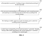
- a first operation is acquired.
- a braking strategy is determined according to the first operation.
- a first parameter corresponding to a first braking part and a second parameter corresponding to a second braking part are determined according to the braking strategy.
- First braking on mobile equipment by the first braking part is controlled according to the first parameter.
- a control signal corresponding to the second parameter is generated.
- Second braking on the mobile equipment by the second braking part is controlled according to the control signal.
- mobile equipment is braked using two braking parts.
- a first braking part brakes through a mechanical structure.
- a second braking part brakes through a circuit structure.
- a braking strength is enhanced by using both the first braking part and the second braking part, reducing a braking distance, enhancing user safety.
- a braking crank is installed on a braking crank case.
- a braking strength detecting device generates, in response to a movement of a handle of the braking crank during braking, a signal of a braking strength corresponding to the movement.
- the braking strength detecting device is set inside the braking crank case.
- the signal of the braking strength is arranged for generating a first force corresponding to a distance by which the handle of the braking crank has moved. A size of the first force changes as the distance changes.
- the first force is an electronic braking force.
- the signal of the braking strength corresponding to the change in the distance by which the handle has moved is generated, thereby generating an electronic braking force corresponding to strength of a braking signal, such that a continuous increasing electronic braking force may be generated during braking, thereby providing a continuous increasing braking force, increasing the braking force, enhancing a braking result.
- FIG. 1 is a flowchart of a controlling method according to an embodiment herein.
- the controlling method applies to mobile equipment having a first braking part and a second braking part.
- the controlling method includes options as follows.
- a first operation is acquired.
- a braking strategy is determined according to the first operation.
- the mobile equipment may be an electric car.
- the electric car may be an electric scooter, an electric bicycle, an electric tricycle, an electric four-wheeler, etc.
- the mobile equipment may have a first braking part and a second braking part.
- the first braking part may brake through a mechanical structure.
- the second braking part may brake through a circuit structure. Accordingly, the first braking part may also be known as a mechanical brake.
- the second braking part may also be known as an electric brake.
- the first operation may be triggered by a user.
- the user may perform the first operation on a mechanical control of the mobile equipment, such that a structure of the mechanical control may be changed.
- the mobile equipment may be an electric bicycle.
- a braking crank of the electric bicycle may be the mechanical control.
- the user may trigger the first operation by clenching the braking crank of the electric bicycle.
- the mechanical control may be connected to the first braking part through a mechanical structure.
- a sensor for detecting a clenching course of the mechanical structure may be provided on the mechanical control.
- the sensor may be connected to the second braking part through a circuit structure.
- the user may perform the first operation on an electronic control of the mobile equipment.
- the electronic control may be connected to the first braking part through an electric structure.
- the electronic control may be connected to the second braking part through a circuit structure.
- the mobile equipment may determine the braking strategy corresponding to the first operation.
- the first braking part and the second braking part may brake according to the braking strategy.
- a braking strength may be enhanced by using both the first braking part and the second braking part.
- a first parameter corresponding to a first braking part and a second parameter corresponding to a second braking part are determined according to the braking strategy.
- braking strengths of the first braking part and the second braking part may be regulated flexibly.
- the braking strength of the first braking part may be determined through the first parameter.
- the braking strength of the second braking part may be determined through the second parameter.
- the control strategy herein may include information on at least a first parameter and a second parameter. The first parameter corresponding to the first braking part and the second parameter corresponding to the second braking part may be determined according to the braking strategy.
- the first parameter may be a parameter for adjusting the mechanical structure of the first braking part.
- the first braking part may be a damping part.
- the damping part may be set near a wheel. When the damping part is pressed against the wheel, the damping part may impede the wheel's movement, thereby braking the mobile equipment.
- the first parameter may be closeness or tightness between the damping part and the wheel, i.e., how close or tight the damping part is pressed against the wheel. The greater the closeness / tightness, i.e., the closer / tighter the damping part is pressed against the wheel, the stronger a braking force is. The less the closeness / tightness, the weaker the braking force is. When the damping part is not pressed against the wheel, the braking strength may be zero.
- the second parameter may be a circuit parameter for adjusting the second braking part.
- the second braking part per se may be the circuit structure.
- a driving part of the mobile equipment may be a motor, for example. Rotation of the motor may drive a wheel of the mobile equipment, thereby driving the mobile equipment.
- the second braking part may brake the mobile equipment as follows. An electric current may be applied to the motor (in a duration which may be determined based on the second parameter), to short circuit a winding of the motor intermittently. When the winding of the motor is short circuited intermittently, rotation of the motor may be stopped, such that no power may be provided to the wheel, thereby braking the mobile equipment.
- first braking on mobile equipment by the first braking part is controlled according to the first parameter.
- the first parameter may be for adjusting the mechanical structure of the first braking part.
- the mobile equipment may be braked by adjusting the mechanical structure of the first braking part according to the first parameter.
- the mobile equipment may be an electric bicycle.
- the user may trigger the first braking by the first braking part by clenching a braking crank of the electric bicycle.
- the braking crank may apply the first braking on the mobile equipment by tightening the first braking part through a brake line.
- the first braking part may be a damping part.
- the damping part may be set near a wheel. When the damping part is pressed against the wheel, the damping part may impede the wheel's movement, thereby braking the mobile equipment.
- a control signal corresponding to the second parameter is generated. Second braking on the mobile equipment by the second braking part is controlled according to the control signal.
- the second parameter may be a circuit parameter for adjusting the second braking part.
- the mobile equipment may be braked by adjusting a circuit parameter of the second braking part according to the second parameter.
- a driving part of the mobile equipment may be a motor, for example. Rotation of the motor may drive a wheel of the mobile equipment, thereby driving the mobile equipment.
- the second braking part may brake the mobile equipment as follows.
- the control signal corresponding to the second parameter may be generated.
- the control signal may be sent to the motor, such that an electric current corresponding to the control signal may be applied to the motor (in a duration which may be determined based on the second parameter), to short circuit a winding of the motor intermittently.
- the winding of the motor is short circuited intermittently, rotation of the motor may be stopped, such that no power may be provided to the wheel, thereby braking the mobile equipment.
- the second braking part may determine, according to the control signal, a locking duration and a driving duration of a driving part within a period of time pre-determined.
- the second braking part may control the driving part to stop driving within the locking duration.
- the driving part may be a motor, for example.
- a three-phase circuit or a two-phase circuit of the motor may be short circuited within the locking duration to stop driving.
- FIG. 2 is a flowchart of a controlling method according to an embodiment herein.
- the controlling method applies to mobile equipment having a first braking part and a second braking part.
- the first braking part may be connected to a moving structure.
- the mobile equipment may further include a sensor for detecting a course of the moving structure.
- the controlling method may include options as follows.
- a course of a moving structure corresponding to the first operation may be detected using a sensor.
- a braking strategy may be determined according to the course.
- the mobile equipment may be an electric car.
- the electric car may be an electric scooter, an electric bicycle, an electric tricycle, an electric four-wheeler, etc.
- the mobile equipment may have a first braking part and a second braking part.
- the first braking part may brake through a mechanical structure.
- the second braking part may brake through a circuit structure. Accordingly, the first braking part may also be known as a mechanical brake.
- the second braking part may also be known as an electric brake.
- the first operation may be triggered by a user.
- the user may perform the first operation on a moving structure of the mobile equipment, such that a course of the moving structure may be changed.
- the mobile equipment may be an electric bicycle.
- a braking crank of the electric bicycle may be the moving structure.
- the user may trigger the first operation by clenching the braking crank of the electric bicycle.
- the moving structure may be connected to the first braking part through a mechanical structure.
- a sensor for detecting a clenching course may be provided on the mechanical control.
- the sensor may be connected to the second braking part through a circuit structure.
- the sensor may detect the course of the moving structure corresponding to the first operation.
- the braking strategy may be determined according to the course.
- the first braking part and the second braking part may brake according to the braking strategy.
- a braking strength may be enhanced by using both the first braking part and the second braking part.
- the sensor may be a potentiometer, a Hall inductive element, etc.
- a first parameter corresponding to a first braking part and a second parameter corresponding to a second braking part are determined according to the braking strategy.
- braking strengths of the first braking part and the second braking part may be regulated flexibly.
- the braking strength of the first braking part may be determined through the first parameter.
- the braking strength of the second braking part may be determined through the second parameter.
- the control strategy herein may include information on at least a first parameter and a second parameter. The first parameter corresponding to the first braking part and the second parameter corresponding to the second braking part may be determined according to the braking strategy.
- the first parameter may be a parameter for adjusting the mechanical structure of the first braking part.
- the first braking part may be a damping part.
- the damping part may be set near a wheel. When the damping part is pressed against the wheel, the damping part may impede the wheel's movement, thereby braking the mobile equipment.
- the first parameter may be closeness or tightness between the damping part and the wheel, i.e., how close or tight the damping part is pressed against the wheel. The greater the closeness / tightness, i.e., the closer / tighter the damping part is pressed against the wheel, the stronger a braking force is. The less the closeness / tightness, the weaker the braking force is. When the damping part is not pressed against the wheel, the braking strength may be zero.
- the second parameter may be a circuit parameter for adjusting the second braking part.
- the second braking part per se may be the circuit structure.
- a driving part of the mobile equipment may be a motor, for example. Rotation of the motor may drive a wheel of the mobile equipment, thereby driving the mobile equipment.
- the second braking part may brake the mobile equipment as follows. An electric current may be applied to the motor (in a duration which may be determined based on the second parameter), to short circuit a winding of the motor intermittently. When the winding of the motor is short circuited intermittently, rotation of the motor may be stopped, such that no power may be provided to the wheel, thereby braking the mobile equipment.
- first braking on mobile equipment by the first braking part is controlled according to the first parameter.
- the first parameter may be for adjusting the mechanical structure of the first braking part.
- the mobile equipment may be braked by adjusting the mechanical structure of the first braking part according to the first parameter.
- the mobile equipment may be an electric bicycle.
- the user may trigger the first braking by the first braking part by clenching a braking crank of the electric bicycle.
- the braking crank may apply the first braking on the mobile equipment by tightening the first braking part through a brake line.
- the first braking part may be a damping part.
- the damping part may be set near a wheel. When the damping part is pressed against the wheel, the damping part may impede the wheel's movement, thereby braking the mobile equipment.
- a control signal corresponding to the second parameter is generated. Second braking on the mobile equipment by the second braking part is controlled according to the control signal.
- a voltage signal output by the sensor may be the control signal.
- the sensor may be provided with a power supply of 5.0V. When the course of the moving structure is zero, the sensor may output 1.0V. When the course of the moving structure is maximal, the sensor may output 4.0V.
- a voltage value here may be exemplary.
- the second parameter may be a circuit parameter for adjusting the second braking part.
- the mobile equipment may be braked by adjusting a circuit parameter of the second braking part according to the second parameter.
- a driving part of the mobile equipment may be a motor, for example. Rotation of the motor may drive a wheel of the mobile equipment, thereby driving the mobile equipment.
- the second braking part may brake the mobile equipment as follows.
- the control signal corresponding to the second parameter may be generated.
- the control signal may be sent to the motor, such that an electric current corresponding to the control signal may be applied to the motor (in a duration which may be determined based on the second parameter), to short circuit a winding of the motor intermittently.
- the winding of the motor is short circuited intermittently, rotation of the motor may be stopped, such that no power may be provided to the wheel, thereby braking the mobile equipment.
- the second braking part may determine, according to the control signal, a locking duration and a driving duration of a driving part within a period of time pre-determined.
- the second braking part may control the driving part to stop driving within the locking duration.
- the driving part may be a motor, for example.
- a three-phase circuit or a two-phase circuit of the motor may be short circuited within the locking duration to stop driving.
- FIG. 3 is a flowchart of a controlling method according to an embodiment herein.
- the controlling method applies to mobile equipment having a first braking part and a second braking part.
- the first braking part may be connected to a moving structure.
- the mobile equipment may further include a sensor for detecting a course of the moving structure.
- the controlling method may include options as follows.
- a course of a moving structure corresponding to the first operation may be detected using a sensor.
- a braking strategy may be determined according to the course.
- the mobile equipment may be an electric car.
- the electric car may be an electric scooter, an electric bicycle, an electric tricycle, an electric four-wheeler, etc.
- the mobile equipment may have a first braking part and a second braking part.
- the first braking part may brake through a mechanical structure.
- the second braking part may brake through a circuit structure. Accordingly, the first braking part may also be known as a mechanical brake.
- the second braking part may also be known as an electric brake.
- the first operation may be triggered by a user.
- the user may perform the first operation on a moving structure of the mobile equipment, such that a course of the moving structure may be changed.
- the mobile equipment may be an electric bicycle.
- a braking crank of the electric bicycle may be the moving structure.
- the user may trigger the first operation by clenching the braking crank of the electric bicycle.
- the moving structure may be connected to the first braking part through a mechanical structure.
- a sensor for detecting a clenching course may be provided on the mechanical control.
- the sensor may be connected to the second braking part through a circuit structure.
- the sensor may detect the course of the moving structure corresponding to the first operation.
- the braking strategy may be determined according to the course.
- the first braking part and the second braking part may brake according to the braking strategy.
- a braking strength may be enhanced by using both the first braking part and the second braking part.
- a first parameter corresponding to a first braking part and a second parameter corresponding to a second braking part are determined according to the braking strategy.
- the first parameter may be made to increase as the course increases.
- the second parameter may be made to increase as the course increases.
- braking strengths of the first braking part and the second braking part may be regulated flexibly.
- the braking strength of the first braking part may be determined through the first parameter.
- the braking strength of the second braking part may be determined through the second parameter.
- the control strategy herein may include information on at least a first parameter and a second parameter. The first parameter corresponding to the first braking part and the second parameter corresponding to the second braking part may be determined according to the braking strategy.
- the first parameter may indicate a braking strength of the first braking part.
- the second parameter may indicate a braking strength of the second braking part.
- the first parameter may be a parameter for adjusting the mechanical structure of the first braking part.
- the first braking part may be a damping part.
- the damping part may be set near a wheel. When the damping part is pressed against the wheel, the damping part may impede the wheel's movement, thereby braking the mobile equipment.
- the first parameter may be closeness or tightness between the damping part and the wheel, i.e., how close or tight the damping part is pressed against the wheel. The greater the closeness / tightness, i.e., the closer / tighter the damping part is pressed against the wheel, the stronger a braking force is. The less the closeness / tightness, the weaker the braking force is. When the damping part is not pressed against the wheel, the braking strength may be zero.
- the second parameter may be a circuit parameter for adjusting the second braking part.
- the second braking part per se may be the circuit structure.
- a driving part of the mobile equipment may be a motor, for example. Rotation of the motor may drive a wheel of the mobile equipment, thereby driving the mobile equipment.
- the second braking part may brake the mobile equipment as follows. An electric current may be applied to the motor (in a duration which may be determined based on the second parameter), to short circuit a winding of the motor intermittently. When the winding of the motor is short circuited intermittently, rotation of the motor may be stopped, such that no power may be provided to the wheel, thereby braking the mobile equipment.
- both the first parameter and the second parameter may be set to zero.
- the first parameter when the course is within a second range, the first parameter may be set to be greater than zero and the second parameter may be set to zero; or the first parameter may be set to zero and the second parameter may be set to be greater than zero.
- both the first parameter and the second parameter may be set to be greater than zero
- the course within the first range may be less than the course within the second range.
- the course within the second range may be less than the course within the third range.
- the moving structure may travel an idle course.
- a first range within a first quarter of a whole course
- braking strengths of both the second braking part and the first braking part may be zero.
- the course of the moving structure falls within a second range (from a first quarter to a second quarter of the whole course)
- the braking strength of either the first braking part or the second braking part is greater than zero.
- the braking strengths of both the second braking part and the first braking part may be greater than zero.
- both the first parameter and the second parameter may be set to zero.
- both the first parameter and the second parameter may be set to be greater than zero.
- the course within the fourth range may be less than the course within the fifth range.
- the moving structure may travel an idle course.
- a fourth range within the first quarter of the whole course
- braking strengths of both the second braking part and the first braking part may be zero.
- the course of the moving structure falls within a fifth range (from the first quarter of the whole course to the whole course)
- the braking strengths of both the second braking part and the first braking part may be greater than zero.
- the first parameter when the course is within a sixth range, the first parameter may be set to be greater than zero and the second parameter may be set to zero; or the first parameter may be set to zero and the second parameter may be set to be greater than zero.
- both the first parameter and the second parameter may be set to be greater than zero
- the course within the sixth range may be less than the course within the seventh range.
- the braking strength of either the second braking part or the first braking part may be zero.
- the braking strengths of both the second braking part and the first braking part may be greater than zero.
- first braking on mobile equipment by the first braking part is controlled according to the first parameter.
- the first parameter may be for adjusting the mechanical structure of the first braking part.
- the mobile equipment may be braked by adjusting the mechanical structure of the first braking part according to the first parameter.
- the mobile equipment may be an electric bicycle.
- the user may trigger the first braking by the first braking part by clenching a braking crank of the electric bicycle.
- the braking crank may apply the first braking on the mobile equipment by tightening the first braking part through a brake line.
- the first braking part may be a damping part.
- the damping part may be set near a wheel. When the damping part is pressed against the wheel, the damping part may impede the wheel's movement, thereby braking the mobile equipment.
- a control signal corresponding to the second parameter is generated. Second braking on the mobile equipment by the second braking part is controlled according to the control signal.
- the second parameter may be a circuit parameter for adjusting the second braking part.
- the mobile equipment may be braked by adjusting a circuit parameter of the second braking part according to the second parameter.
- a driving part of the mobile equipment may be a motor, for example. Rotation of the motor may drive a wheel of the mobile equipment, thereby driving the mobile equipment.
- the second braking part may brake the mobile equipment as follows.
- the control signal corresponding to the second parameter may be generated.
- the control signal may be sent to the motor, such that an electric current corresponding to the control signal may be applied to the motor (in a duration which may be determined based on the second parameter), to short circuit a winding of the motor intermittently.
- the winding of the motor is short circuited intermittently, rotation of the motor may be stopped, such that no power may be provided to the wheel, thereby braking the mobile equipment.
- a voltage signal output by the sensor may be the control signal.
- the sensor may be provided with a power supply of 5.0V. When the course of the moving structure is zero, the sensor may output 1.0V. When the course of the moving structure is maximal, the sensor may output 4.0V.
- a voltage value here may be exemplary.
- 1.0V may correspond to a duty cycle of 10%.
- 4.0V may correspond to a duty cycle of 100%.
- a sensor outputs 3V two phases of the motor may be short circuited with a duty cycle of 70%.
- the second braking part may determine, according to the control signal, a locking duration and a driving duration of a driving part within a period of time pre-determined.
- the second braking part may control the driving part to stop driving within the locking duration.
- the driving part may be a motor, for example.
- a three-phase circuit or a two-phase circuit of the motor may be short circuited within the locking duration to stop driving.
- FIG. 6 is a diagram of a structure of mobile equipment according to an embodiment herein. As shown in FIG. 6 , the mobile equipment has a first braking part 61 and a second braking part 62. The mobile equipment includes a processor 63.
- the processor 63 is arranged for: acquiring a first operation; determining, according to the first operation, a braking strategy; determining, according to the braking strategy, a first parameter corresponding to the first braking part 61 and a second parameter corresponding to the second braking part 62.
- the first braking part 61 is arranged for: performing, according to the first parameter, first braking on the mobile equipment.
- the second braking part 62 is arranged for: generating a control signal corresponding to the second parameter; performing, according to the control signal, second braking on the mobile equipment.
- FIG. 7 is a diagram of a structure of mobile equipment according to an embodiment herein. As shown in FIG. 7 , the mobile equipment has a first braking part 71 and a second braking part 72. The mobile equipment includes a processor 73.
- the processor 73 is arranged for: acquiring a first operation; determining, according to the first operation, a braking strategy; determining, according to the braking strategy, a first parameter corresponding to the first braking part 71 and a second parameter corresponding to the second braking part 72.
- the first braking part 71 is arranged for: performing, according to the first parameter, first braking on the mobile equipment.
- the second braking part 72 is arranged for: generating a control signal corresponding to the second parameter; performing, according to the control signal, second braking on the mobile equipment.
- the first braking part 71 may be connected to a moving structure 74.
- the mobile equipment may further include a sensor 75 for detecting a course of the moving structure 74.
- the sensor 75 may be arranged for: in response to acquiring the first operation, detecting a course of the moving structure 74 corresponding to the first operation.
- the processor 73 may further be arranged for: determining, according to the course, the braking strategy.
- the first parameter may indicate a braking strength of the first braking part 71.
- the second parameter may indicate a braking strength of the second braking part 72.
- both the first parameter and the second parameter may be set to zero.
- the first parameter when the course is within a second range, the first parameter may be set to be greater than zero and the second parameter may be set to zero; or the first parameter may be set to zero and the second parameter may be set to be greater than zero.
- both the first parameter and the second parameter may be set to be greater than zero
- the course within the first range may be less than the course within the second range.
- the course within the second range may be less than the course within the third range.
- the first parameter may indicate a braking strength of the first braking part 71.
- the second parameter may indicate a braking strength of the second braking part 72.
- both the first parameter and the second parameter may be set to zero.
- both the first parameter and the second parameter may be set to be greater than zero.
- the course within the fourth range may be less than the course within the fifth range.
- the first parameter may indicate a braking strength of the first braking part 71.
- the second parameter may indicate a braking strength of the second braking part 72.
- the first parameter when the course is within a sixth range, the first parameter may be set to be greater than zero and the second parameter may be set to zero; or the first parameter may be set to zero and the second parameter may be set to be greater than zero.
- both the first parameter and the second parameter may be set to be greater than zero
- the course within the sixth range may be less than the course within the seventh range.
- the first parameter when the first parameter is greater than zero, the first parameter may be made to increase as the course increases.
- the second parameter when the second parameter is greater than zero, the second parameter may be made to increase as the course increases.
- the second braking part 72 may further be arranged for: determining, according to the control signal, a locking duration and a driving duration of a driving part within a period of time pre-determined; controlling the driving part to stop driving within the locking duration.
- a conventional electric braking crank may provide, during braking, a controller with but a simple signal. Having received the signal, the controller may control a braking part to output a constant electronic braking force. That is, a conventional electric braking crank may serve as a normally open / closed switch. When a handle is clenched such that the handle reaches a maximal displacement thereof, the electric braking crank may output to the controller a signal indicating but to brake. Having received the signal, the controller may control a braking part to output a constant electronic braking force, in which case a braking force may be weakened greatly, which may lead to poor user experience during braking.
- a braking crank is installed on a braking crank case.
- a braking strength detecting device generates, in response to a movement of a handle of the braking crank during braking, a signal of a braking strength corresponding to the movement.
- the braking strength detecting device is set inside the braking crank case.
- the signal of the braking strength is arranged for generating a first force corresponding to a distance by which the handle of the braking crank has moved (i.e., the course).
- a size of the first force may change as the distance changes.
- the first force is an electronic braking force.
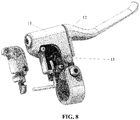
- a braking crank device includes a braking crank case 11, a braking crank 12, and a braking strength detecting device 13.
- the braking crank 12 is installed on the braking crank case 11.
- the braking strength detecting device 13 is set inside the braking crank case 11.
- the braking strength detecting device is arranged for generating, in response to a movement of a handle of the braking crank 12 during braking, a signal of a braking strength corresponding to the movement.
- the signal of the braking strength is arranged for generating a first force corresponding to a distance by which the handle of the braking crank has moved (i.e., the course).
- a size of the first force may change as the distance changes.
- the first force is an electronic braking force.
- a braking strength detecting device 13 may detect a signal of a braking strength corresponding to the constantly changing distance, to generate an electronic braking force corresponding to the constantly changing distance under control of a controller.
- the signal of the braking strength may instruct to stop outputting a driving force that drives mobile equipment.
- the signal of the braking strength may instruct the controller to stop providing the mobile equipment with the driving force.
- the controller may receive the changing signal of the braking strength output by the braking strength detecting device 13. In this case, the controller may generate a control signal according to the signal of the braking strength, such that the mobile equipment is no longer provided with the driving force. Meanwhile, the controller may generate a control signal corresponding to the constantly changing signal of the braking strength, to generate an electronic braking force corresponding to the constantly changing distance, such that the mobile equipment may be braked.
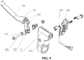
- the braking strength detecting device 13 may be a Hall element 131.
- the braking crank device may further include a magnet 132.
- the magnet 132 may be arranged for moving with displacement of the handle of the braking crank 12 during braking.
- the Hall element 131 may be arranged for detecting strength of a magnetic field generated by the magnet 132 during movement, and generating, according to the strength of the magnetic field detected, the signal of the braking strength corresponding to the movement.
- the Hall element 131 may be a linear Hall element.
- the magnet 132 may be of magnetic steel (permanent magnet).
- the magnet 132 may be set on an extending part 122 integral to the handle 121 of the braking crank 12.
- the extending part 122 may be set with a first hole for connection 123.
- the braking crank case 11 may be set with a second hole for connection 111 corresponding to the first hole for connection 123.
- a braking crank shaft 124 may be arranged for installing the braking crank 11 on the braking crank case 11 by passing through the first hole for connection 123 and the second hole for connection 111.
- the braking crank 12 may move within a range of locations along the braking crank shaft 124.
- the braking crank case 11 may be set with a Hall base 112.
- the Hall element 131 may be secured on the Hall base 112.
- the Hall element 131 may be arranged for not moving with the displacement of the handle 121 of the braking crank 12.
- the magnet 132 may move with movement of the handle 121 of the braking crank 12.
- the Hall element 131 may be secured and may not move. Therefore, while the magnet 132 is moving, a location of the Hall element 131 with respect to the magnet 132 may change, such that the Hall element 131 may detect the strength of the magnetic field generated by the magnet at different locations (which may be construed by the Hall element 131 as change in magnetic induction). The strength of the magnetic field at different locations may reflect indirectly the signal of the braking strength corresponding to the locations.
- the Hall element 131 may convert the detected strength of the magnetic field into a linear analog electric (voltage or current) signal, to generate a linear electronic braking force corresponding to the constantly changing distance under control of a controller.
- the Hall element 131 and the magnet 132 may have to be set such that the magnet 132 generates a magnetic field oriented parallel to the Hall element 131 (i.e., a sensing surface of the Hall element is perpendicular to the orientation of the magnetic field), to allow the Hall element 131 to detect accurately the strength of the magnetic field of the magnet 132 at different locations while the magnet 132 is moving.
- a controller may receive not only a displacement signal output by a displacement detecting device, but also a linear analog electric signal output by a Hall element 131.
- the controller may generate a control signal according to the linear analog electric signal so as to stop providing mobile equipment with a driving force.
- the controller may generate a control signal corresponding to the linear analog electric signal, to generate an electronic braking force with linearly increasing strength, such that the mobile equipment may be braked.
- another auxiliary part such as a heat shrinkable tube, a screw, a nut, a recovering part (to recover a braking crank 12 after it has moved), a signal line, etc., may be required to set and connect the Hall element 131, the Hall base 112, the braking crank shaft 124, etc.
- a braking crank 12 is installed on a braking crank case 11.
- a braking strength detecting device 13 set inside the braking crank case 11 generates a signal of a braking strength corresponding to movement of a handle of the braking crank 12 while the handle is moving.
- the signal of the braking strength may be arranged for generating a first force corresponding to a distance by which the handle of the braking crank 12 has moved.
- a size of the first force may change as the distance changes.
- the first force is an electronic braking force.
- the signal of the braking strength corresponding to the change in the distance by which the handle has moved is generated, thereby generating an electronic braking force corresponding to strength of a braking signal, such that a continuous increasing electronic braking force may be generated during braking, thereby providing a continuous increasing braking force, increasing the braking force, enhancing a braking result.
- a signal corresponding to a braking strength may be detected by coordination between a linear Hall element 131 and a magnet 132, such that the signal of the braking strength corresponding to a distance by which a handle has moved may be detected accurately.
- a braking device 01 based on an aforementioned embodiment may include a braking crank device 10, a controller 20, and a braking part 30.
- the braking crank device 10 includes a braking crank case 11, a braking crank, and a braking strength detecting device.
- the braking crank 12 is installed on the braking crank case 11.
- the braking strength detecting device 13 is set inside the braking crank case 11.
- the braking strength detecting device may be arranged for: generating, in response to a movement of a handle of the braking crank during braking, a signal of a braking strength corresponding to the movement, and outputting the signal of the braking strength to the controller 20.
- the controller 20 may be arranged for: generating, according to the signal of the braking strength, a first control signal; controlling, according to the first control signal, electric braking on a driving part by the braking part 30.
- a size of a braking force thereof may change as a distance by which the handle of the braking crank has moved changes.
- the braking part 30 may brake through a circuit structure.
- the braking part per se may be the circuit structure.
- a driving part may be a motor, for example. Rotation of the motor may drive a wheel of the mobile equipment, thereby driving the mobile equipment.
- the braking part 30 may brake the mobile equipment as follows. An electric current may be applied to the motor (in a duration which may be determined by the controller 20 according to the signal of the braking strength corresponding to the movement), to short circuit a winding of the motor intermittently. When the winding of the motor is short circuited intermittently, rotation of the motor may be stopped, such that no power may be provided to the wheel, thereby braking the mobile equipment.
- a braking strength detecting device 13 may detect a signal of a braking strength corresponding to a constantly changing distance, and output the generated signal to the controller 20.
- the controller 20 may constantly output a control signal to the braking part 30 according to the signal of the braking strength, to control the braking part 30 to apply, to the driving part, an electric braking force of a size corresponding to the constantly changing distance.
- the controller 20 may further be arranged for generating, according to the signal of the braking strength, a second control signal to stop outputting a driving force that drives mobile equipment (i.e., controlling the driving part to stop generating a driving force).
- the signal of the braking strength may instruct the controller 20 to stop providing the mobile equipment with the driving force.
- a controller 20 may receive a changing signal of a braking strength output by a braking strength detecting device 13. In this case, the controller 20 may generate a control signal according to the signal of the braking strength to control a driving part to stop providing mobile equipment with a driving force. Meanwhile, the controller 20 may constantly output a control signal to the braking part 30 according to the signal of the braking strength, to control the braking part 30 to apply, to the driving part, an electric braking force of a size corresponding to the constantly changing distance, such that the mobile equipment may be braked.
- the braking strength detecting device 13 may be a Hall element 131.
- the braking crank device 10 may further include a magnet 132.
- the magnet 132 may be arranged for moving with displacement of the handle of the braking crank 12 during braking.
- the Hall element 131 may be arranged for detecting strength of a magnetic field generated by the magnet 132 during movement, and generating, according to the strength of the magnetic field detected, the signal of the braking strength corresponding to the movement.
- the Hall element 131 may be a linear Hall element.
- the magnet 132 may be of magnetic steel (permanent magnet).
- the magnet 132 may be set on an extending part 122 integral to the handle 121 of the braking crank 12.
- the extending part 122 may be set with a first hole for connection 123.
- the braking crank case 11 may be set with a second hole for connection 111 corresponding to the first hole for connection 123.
- a braking crank shaft 124 may be arranged for installing the braking crank 11 on the braking crank case 11 by passing through the first hole for connection 123 and the second hole for connection 111.
- the braking crank 12 may move within a range of locations along the braking crank shaft 124.
- the braking crank case 11 may be set with a Hall base 112.
- the Hall element 131 may be secured on the Hall base 112.
- the Hall element 131 may be arranged for not moving with the displacement of the handle 121 of the braking crank 12.
- the magnet 132 may move with movement of the handle 121 of the braking crank 12.
- the Hall element 131 may be secured and may not move. Therefore, while the magnet 132 is moving, a location of the Hall element 131 with respect to the magnet 132 may change, such that the Hall element 131 may detect the strength of the magnetic field generated by the magnet at different locations (which may be construed by the Hall element 131 as change in magnetic induction). The strength of the magnetic field at different locations may reflect indirectly the signal of the braking strength corresponding to the locations.
- the Hall element 131 may convert the detected strength of the magnetic field into a linear analog electric (voltage or current) signal, to generate a linear electronic braking force corresponding to the constantly changing distance under control of a controller.
- the Hall element 131 and the magnet 132 may have to be set such that the magnet 132 generates a magnetic field oriented parallel to the Hall element 131 (i.e., a sensing surface of the Hall element is perpendicular to the orientation of the magnetic field), to allow the Hall element 131 to detect the strength of the magnetic field of the magnet 132 at different locations while the magnet 132 is moving.
- a controller may receive not only a displacement signal output by a displacement detecting device, but also a linear analog electric signal output by a Hall element 131.
- the controller 20 may generate a control signal according to the linear analog electric signal so as to stop providing mobile equipment with a driving force.
- the controller 20 may generate a control signal corresponding to the linear analog electric signal, to generate an electronic braking force with linearly increasing strength, such that the mobile equipment may be braked.
- another auxiliary part such as a heat shrinkable tube, a screw, a nut, a recovering part (to recover a braking crank 12 after it has moved), a signal line, etc., may be required to set and connect the Hall element 131, the Hall base 112, the braking crank shaft 124, etc.
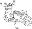
- the braking device may include a braking crank device 10, a controller, and a braking part (not shown in FIG. 4 ).
- the mobile equipment may be an electric bicycle (as shown in FIG. 4 ), an electric scooter, an electric tricycle, an electric four-wheeler, etc.
- a braking crank 12 is installed on a braking crank case 11.
- a braking strength detecting device 13 set inside the braking crank case 11 generates a signal of a braking strength corresponding to movement of a handle of the braking crank 12 while the handle is moving.
- the signal of the braking strength may be arranged for generating a first force corresponding to a distance by which the handle of the braking crank 12 has moved.
- a size of the first force may change as the distance changes.
- the first force is an electronic braking force.
- the signal of the braking strength corresponding to the change in the distance by which the handle has moved is generated, thereby generating an electronic braking force corresponding to strength of a braking signal, such that a continuous increasing electronic braking force may be generated during braking, thereby providing a continuous increasing braking force, increasing the braking force, enhancing a braking result.
- a signal corresponding to a braking strength may be detected by coordination between a linear Hall element 131 and a magnet 132, such that the signal of the braking strength corresponding to a distance by which a handle has moved may be detected accurately.
Landscapes
- Engineering & Computer Science (AREA)
- Mechanical Engineering (AREA)
- Transportation (AREA)
- Power Engineering (AREA)
- Physics & Mathematics (AREA)
- Electromagnetism (AREA)
- Regulating Braking Force (AREA)
- Electric Propulsion And Braking For Vehicles (AREA)
Abstract
Description
- This application is based on, and claims benefit of priority to, Chinese Applications No.
201610204341.X filed on April 01, 2016 201620752059.0 filed on July 15, 2016 - The present disclosure relates to control technology, and in particular to a controlling method, mobile equipment, a braking crank device, and a braking device.
- An electric car finds wide use due to environment friendliness and convenience thereof. There are various kinds of electric cars, such as an electric bicycle, an electric tricycle, an electric four-wheeler, etc. Braking performance of an electric car is a key factor considered by a user. Good braking performance may guarantee user safety.
- An existing electric car brakes as follows. When it is detected during a ride that a braking crank has been pressed, power supply of a motor may be cut off. In this case, braking is implemented completely by a mechanical structure. Such a braking mode provides a weak braking strength, which leads to a long braking distance. In this case, a dangerous accident tends to happen. In addition, a conventional electric braking crank, limited by an internal structure thereof, may provide, during braking, a controller with but a simple signal, such that the controller may control a braking part to output but a constant electronic braking force, in which case a braking force may be weakened greatly.
- Embodiments herein provide a controlling method, mobile equipment, a braking crank device, and a braking device.
- According to an embodiment herein, a controlling method applies to mobile equipment. The mobile equipment has a first braking part and a second braking part. The controlling method includes:
- acquiring a first operation; determining, according to the first operation, a braking strategy;
- determining, according to the braking strategy, a first parameter corresponding to the first braking part and a second parameter corresponding to the second braking part;
- controlling, according to the first parameter, first braking on the mobile equipment by the first braking part;
- generating a control signal corresponding to the second parameter; and controlling, according to the control signal, second braking on the mobile equipment by the second braking part.
- The first braking part may be connected to a moving structure. The mobile equipment may further include a sensor for detecting a course of the moving structure.
- The acquiring a first operation; determining, according to the first operation, a braking strategy may include:
- in response to acquiring the first operation, detecting, using the sensor, a course of the moving structure corresponding to the first operation; and
- determining, according to the course, the braking strategy.
- The first parameter may indicate a braking strength of the first braking part. The second parameter may indicate a braking strength of the second braking part. The braking strategy may include:
- in response to the course being within a first range, setting both the first parameter and the second parameter to zero;
- in response to the course being within a second range, setting the first parameter to be greater than zero and the second parameter to zero; or setting the first parameter to zero and the second parameter to be greater than zero; and / or
- in response to the course being within a third range, setting both the first parameter and the second parameter to be greater than zero.
- The course within the first range may be less than the course within the second range. The course within the second range may be less than the course within the third range.
- The first parameter may indicate a braking strength of the first braking part. The second parameter may indicate a braking strength of the second braking part. The braking strategy may include:
- in response to the course being within a fourth range, setting both the first parameter and the second parameter to zero; and / or
- in response to the course being within a fifth range, setting both the first parameter and the second parameter to be greater than zero.
- The course within the fourth range may be less than the course within the fifth range.
- The first parameter may indicate a braking strength of the first braking part. The second parameter may indicate a braking strength of the second braking part. The braking strategy may include:
- in response to the course being within a sixth range, setting the first parameter to be greater than zero and the second parameter to zero; or setting the first parameter to zero and the second parameter to be greater than zero; and / or
- in response to the course being within a seventh range, setting both the first parameter and the second parameter to be greater than zero.
- The course within the sixth range may be less than the course within the seventh range.
- The braking strategy may further include:
- in response to the first parameter being greater than zero, increasing the first parameter as the course increases; and / or
- in response to the second parameter being greater than zero, increasing the second parameter as the course increases.
- The controlling, according to the control signal, second braking on the mobile equipment by the second braking part may include:
- controlling the second braking part to determine, according to the control signal, a locking duration and a driving duration of a driving part within a period of time pre-determined;
- controlling the driving part to stop driving within the locking duration.
- Mobile equipment according to an embodiment herein has a first braking part and a second braking part. The mobile equipment includes a processor.
- The processor is arranged for: acquiring a first operation; determining, according to the first operation, a braking strategy; determining, according to the braking strategy, a first parameter corresponding to the first braking part and a second parameter corresponding to the second braking part.
- The first braking part may be arranged for: performing, according to the first parameter, first braking on the mobile equipment.
- The second braking part may be arranged for: generating a control signal corresponding to the second parameter; performing, according to the control signal, second braking on the mobile equipment.
- The first braking part may be connected to a moving structure. The mobile equipment may further include a sensor for detecting a course of the moving structure.
- The sensor may be arranged for: in response to acquiring the first operation, detecting a course of the moving structure corresponding to the first operation.
- The processor may be further arranged for: determining, according to the course, the braking strategy.
- The first parameter may indicate a braking strength of the first braking part. The second parameter may indicate a braking strength of the second braking part. The braking strategy may include:
- in response to the course being within a first range, setting both the first parameter and the second parameter to zero;
- in response to the course being within a second range, setting the first parameter to be greater than zero and the second parameter to zero; or setting the first parameter to zero and the second parameter to be greater than zero; and / or
- in response to the course being within a third range, setting both the first parameter and the second parameter to be greater than zero.
- The course within the first range may be less than the course within the second range. The course within the second range may be less than the course within the third range.
- The first parameter may indicate a braking strength of the first braking part. The second parameter may indicate a braking strength of the second braking part. The braking strategy may include:
- in response to the course being within a fourth range, setting both the first parameter and the second parameter to zero; and / or
- in response to the course being within a fifth range, setting both the first parameter and the second parameter to be greater than zero.
- The course within the fourth range may be less than the course within the fifth range.
- The first parameter may indicate a braking strength of the first braking part. The second parameter may indicate a braking strength of the second braking part. The braking strategy may include:
- in response to the course being within a sixth range, setting the first parameter to be greater than zero and the second parameter to zero; or setting the first parameter to zero and the second parameter to be greater than zero; and / or
- in response to the course being within a seventh range, setting both the first parameter and the second parameter to be greater than zero.
- The course within the sixth range may be less than the course within the seventh range.
- The braking strategy may further include:
- in response to the first parameter being greater than zero, increasing the first parameter as the course increases; and / or
- in response to the second parameter being greater than zero, increasing the second parameter as the course increases.
- The second braking part may be further arranged for: determining, according to the control signal, a locking duration and a driving duration of a driving part within a period of time pre-determined; controlling the driving part to stop driving within the locking duration.
- A braking crank device according to an embodiment herein includes:
- a braking crank case;
- a braking crank installed on the braking crank case; and
- a braking strength detecting device arranged for generating, in response to a movement of a handle of the braking crank during braking, a signal of a braking strength corresponding to the movement.
- The braking strength detecting device is set inside the braking crank case.
- The signal of the braking strength is arranged for generating a first force corresponding to a distance by which the handle of the braking crank has moved. A size of the first force changes as the distance changes. The first force is an electronic braking force.
- The braking strength detecting device may be a Hall element. The braking crank device may further include a magnet.
- The magnet may be arranged for moving with displacement of the handle of the braking crank during braking.
- The Hall element may be arranged for: detecting strength of a magnetic field generated by the magnet during movement, and generating, according to the strength of the magnetic field detected, the signal of the braking strength corresponding to the movement.
- The magnet may be set on an extending part integral to the handle.
- The extending part may be set with a first hole for connection. The braking crank case may be set with a second hole for connection corresponding to the first hole for connection.
- A braking crank shaft may be arranged for installing the braking crank on the braking crank case by passing through the first hole for connection and the second hole for connection.
- The braking crank case may be set with a Hall base. The Hall element may be secured on the Hall base. The Hall element may be arranged for not moving with the displacement of the handle of the braking crank.
- The signal of the braking strength may be arranged for instructing to stop outputting a driving force that drives mobile equipment.
- A braking device according to an embodiment herein includes a braking crank device. The braking crank device includes:
- a braking crank case;
- a braking crank installed on the braking crank case; and
- a braking strength detecting device arranged for generating, in response to a movement of a handle of the braking crank during braking, a signal of a braking strength corresponding to the movement.
- The braking strength detecting device is set inside the braking crank case.
- The braking device further includes:
- a braking part; and
- a controller arranged for: generating, according to the signal of the braking strength, a first control signal; controlling, according to the first control signal, electric braking on a driving part by the braking part. A size of a braking force thereof changes as a distance by which the handle of the braking crank has moved changes.
- The braking strength detecting device is arranged for outputting the signal of the braking strength to the controller.
- The braking strength detecting device may be a Hall element. The braking crank device may further include a magnet.
- The magnet may be arranged for moving with displacement of the handle of the braking crank during braking.
- The Hall element may be arranged for: detecting strength of a magnetic field generated by the magnet during movement, and generating, according to the strength of the magnetic field detected, the signal of the braking strength corresponding to the movement.
- The magnet may be set on an extending part integral to the handle.
- The extending part may be set with a first hole for connection. The braking crank case may be set with a second hole for connection corresponding to the first hole for connection.
- A braking crank shaft may be arranged for installing the braking crank on the braking crank case by passing through the first hole for connection and the second hole for connection.
- The braking crank case may be set with a Hall base. The Hall element may be secured on the Hall base. The Hall element may be arranged for not moving with the displacement of the handle of the braking crank.
- The controller may be arranged for generating, according to the signal of the braking strength, a second control signal to stop outputting a driving force that drives mobile equipment.
- Mobile equipment according to an embodiment herein includes an aforementioned braking device.
- With a technical solution according to at least one embodiment herein, a first operation is acquired. A braking strategy is determined according to the first operation. A first parameter corresponding to a first braking part and a second parameter corresponding to a second braking part are determined according to the braking strategy. First braking on mobile equipment by the first braking part is controlled according to the first parameter. A control signal corresponding to the second parameter is generated. Second braking on the mobile equipment by the second braking part is controlled according to the control signal. With embodiments herein, mobile equipment is braked using two braking parts. A first braking part brakes through a mechanical structure. A second braking part brakes through a circuit structure. A braking strength is enhanced by using both the first braking part and the second braking part, reducing a braking distance, enhancing user safety.
- With a technical solution according to at least one embodiment herein, a braking crank is installed on a braking crank case. A braking strength detecting device generates, in response to a movement of a handle of the braking crank during braking, a signal of a braking strength corresponding to the movement. The braking strength detecting device is set inside the braking crank case. The signal of the braking strength is arranged for generating a first force corresponding to a distance by which the handle of the braking crank has moved. A size of the first force changes as the distance changes. The first force is an electronic braking force. During braking, the signal of the braking strength corresponding to the change in the distance by which the handle has moved is generated, thereby generating an electronic braking force corresponding to strength of a braking signal, such that a continuous increasing electronic braking force may be generated during braking, thereby providing a continuous increasing braking force, increasing the braking force, enhancing a braking result. By providing braking with an electronic braking force of a size changing with change in a distance by which a handle of a braking crank has moved, somatosensory control of a size of an electronic braking force by a user is enabled, enhancing a braking precision, improving braking experience.
-
-
FIG. 1 is a flowchart of a controlling method according to an embodiment herein. -
FIG. 2 is a flowchart of a controlling method according to an embodiment herein. -
FIG. 3 is a flowchart of a controlling method according to an embodiment herein. -
FIG. 4 is a diagram of an entity of mobile equipment according to an embodiment herein. -
FIG. 5 is a diagram of a course of a moving part according to an embodiment herein. -
FIG. 6 is a diagram of a structure of mobile equipment according to an embodiment herein. -
FIG. 7 is a diagram of a structure of mobile equipment according to an embodiment herein. -
FIG. 8 is a diagram of a structure of a braking crank device according to an embodiment herein. -
FIG. 9 is an exploded view of a structure of a braking crank device according to an embodiment herein. -
FIG. 10 is a diagram of a structure of a braking device according to an embodiment herein. - Embodiments herein are elaborated below with reference to the drawings to allow a more thorough understanding of a feature and technical content of an embodiment herein. The drawings herein are but for reference and explanation, and are not intended to limit an embodiment herein.
-
FIG. 1 is a flowchart of a controlling method according to an embodiment herein. The controlling method applies to mobile equipment having a first braking part and a second braking part. As shown inFIG. 1 , the controlling method includes options as follows. - In
option 101, a first operation is acquired. A braking strategy is determined according to the first operation. - The mobile equipment may be an electric car. The electric car may be an electric scooter, an electric bicycle, an electric tricycle, an electric four-wheeler, etc.
- The mobile equipment may have a first braking part and a second braking part. The first braking part may brake through a mechanical structure. The second braking part may brake through a circuit structure. Accordingly, the first braking part may also be known as a mechanical brake. The second braking part may also be known as an electric brake.
- The first operation may be triggered by a user. The user may perform the first operation on a mechanical control of the mobile equipment, such that a structure of the mechanical control may be changed. Referring to
FIG. 4 , the mobile equipment may be an electric bicycle. A braking crank of the electric bicycle may be the mechanical control. The user may trigger the first operation by clenching the braking crank of the electric bicycle. The mechanical control may be connected to the first braking part through a mechanical structure. A sensor for detecting a clenching course of the mechanical structure may be provided on the mechanical control. The sensor may be connected to the second braking part through a circuit structure. In an embodiment herein, the user may perform the first operation on an electronic control of the mobile equipment. The electronic control may be connected to the first braking part through an electric structure. The electronic control may be connected to the second braking part through a circuit structure. - Having acquired the first operation, the mobile equipment may determine the braking strategy corresponding to the first operation. The first braking part and the second braking part may brake according to the braking strategy. With the braking strategy, a braking strength may be enhanced by using both the first braking part and the second braking part.
- In
option 102, a first parameter corresponding to a first braking part and a second parameter corresponding to a second braking part are determined according to the braking strategy. - With the braking strategy, braking strengths of the first braking part and the second braking part may be regulated flexibly. The braking strength of the first braking part may be determined through the first parameter. The braking strength of the second braking part may be determined through the second parameter. The control strategy herein may include information on at least a first parameter and a second parameter. The first parameter corresponding to the first braking part and the second parameter corresponding to the second braking part may be determined according to the braking strategy.
- As the first braking part brakes through a mechanical structure, the first parameter may be a parameter for adjusting the mechanical structure of the first braking part. For example, the first braking part may be a damping part. The damping part may be set near a wheel. When the damping part is pressed against the wheel, the damping part may impede the wheel's movement, thereby braking the mobile equipment. The first parameter may be closeness or tightness between the damping part and the wheel, i.e., how close or tight the damping part is pressed against the wheel. The greater the closeness / tightness, i.e., the closer / tighter the damping part is pressed against the wheel, the stronger a braking force is. The less the closeness / tightness, the weaker the braking force is. When the damping part is not pressed against the wheel, the braking strength may be zero.
- As the second braking part brakes through a circuit structure, the second parameter may be a circuit parameter for adjusting the second braking part. The second braking part per se may be the circuit structure. A driving part of the mobile equipment may be a motor, for example. Rotation of the motor may drive a wheel of the mobile equipment, thereby driving the mobile equipment. The second braking part may brake the mobile equipment as follows. An electric current may be applied to the motor (in a duration which may be determined based on the second parameter), to short circuit a winding of the motor intermittently. When the winding of the motor is short circuited intermittently, rotation of the motor may be stopped, such that no power may be provided to the wheel, thereby braking the mobile equipment.
- In
option 103, first braking on mobile equipment by the first braking part is controlled according to the first parameter. - The first parameter may be for adjusting the mechanical structure of the first braking part. The mobile equipment may be braked by adjusting the mechanical structure of the first braking part according to the first parameter.
- Referring to
FIG. 4 , the mobile equipment may be an electric bicycle. The user may trigger the first braking by the first braking part by clenching a braking crank of the electric bicycle. The braking crank may apply the first braking on the mobile equipment by tightening the first braking part through a brake line. The first braking part may be a damping part. The damping part may be set near a wheel. When the damping part is pressed against the wheel, the damping part may impede the wheel's movement, thereby braking the mobile equipment. - In
option 104, a control signal corresponding to the second parameter is generated. Second braking on the mobile equipment by the second braking part is controlled according to the control signal. - The second parameter may be a circuit parameter for adjusting the second braking part. The mobile equipment may be braked by adjusting a circuit parameter of the second braking part according to the second parameter.
- A driving part of the mobile equipment may be a motor, for example. Rotation of the motor may drive a wheel of the mobile equipment, thereby driving the mobile equipment. The second braking part may brake the mobile equipment as follows. The control signal corresponding to the second parameter may be generated. The control signal may be sent to the motor, such that an electric current corresponding to the control signal may be applied to the motor (in a duration which may be determined based on the second parameter), to short circuit a winding of the motor intermittently. When the winding of the motor is short circuited intermittently, rotation of the motor may be stopped, such that no power may be provided to the wheel, thereby braking the mobile equipment.
- The second braking part may determine, according to the control signal, a locking duration and a driving duration of a driving part within a period of time pre-determined. The second braking part may control the driving part to stop driving within the locking duration. The driving part may be a motor, for example. A three-phase circuit or a two-phase circuit of the motor may be short circuited within the locking duration to stop driving.
-
FIG. 2 is a flowchart of a controlling method according to an embodiment herein. The controlling method applies to mobile equipment having a first braking part and a second braking part. The first braking part may be connected to a moving structure. The mobile equipment may further include a sensor for detecting a course of the moving structure. As shown inFIG. 2 , the controlling method may include options as follows. - In
option 201, when a first operation is acquired, a course of a moving structure corresponding to the first operation may be detected using a sensor. A braking strategy may be determined according to the course. - The mobile equipment may be an electric car. The electric car may be an electric scooter, an electric bicycle, an electric tricycle, an electric four-wheeler, etc.
- The mobile equipment may have a first braking part and a second braking part. The first braking part may brake through a mechanical structure. The second braking part may brake through a circuit structure. Accordingly, the first braking part may also be known as a mechanical brake. The second braking part may also be known as an electric brake.
- The first operation may be triggered by a user. The user may perform the first operation on a moving structure of the mobile equipment, such that a course of the moving structure may be changed. Referring to
FIG. 4 , the mobile equipment may be an electric bicycle. A braking crank of the electric bicycle may be the moving structure. The user may trigger the first operation by clenching the braking crank of the electric bicycle. The moving structure may be connected to the first braking part through a mechanical structure. A sensor for detecting a clenching course may be provided on the mechanical control. The sensor may be connected to the second braking part through a circuit structure. - Having acquired the first operation, the sensor may detect the course of the moving structure corresponding to the first operation. The braking strategy may be determined according to the course. The first braking part and the second braking part may brake according to the braking strategy. With the braking strategy, a braking strength may be enhanced by using both the first braking part and the second braking part.
- The sensor may be a potentiometer, a Hall inductive element, etc.
- In
option 202, a first parameter corresponding to a first braking part and a second parameter corresponding to a second braking part are determined according to the braking strategy. - With the braking strategy, braking strengths of the first braking part and the second braking part may be regulated flexibly. The braking strength of the first braking part may be determined through the first parameter. The braking strength of the second braking part may be determined through the second parameter. The control strategy herein may include information on at least a first parameter and a second parameter. The first parameter corresponding to the first braking part and the second parameter corresponding to the second braking part may be determined according to the braking strategy.
- As the first braking part brakes through a mechanical structure, the first parameter may be a parameter for adjusting the mechanical structure of the first braking part. For example, the first braking part may be a damping part. The damping part may be set near a wheel. When the damping part is pressed against the wheel, the damping part may impede the wheel's movement, thereby braking the mobile equipment. The first parameter may be closeness or tightness between the damping part and the wheel, i.e., how close or tight the damping part is pressed against the wheel. The greater the closeness / tightness, i.e., the closer / tighter the damping part is pressed against the wheel, the stronger a braking force is. The less the closeness / tightness, the weaker the braking force is. When the damping part is not pressed against the wheel, the braking strength may be zero.
- As the second braking part brakes through a circuit structure, the second parameter may be a circuit parameter for adjusting the second braking part. The second braking part per se may be the circuit structure. A driving part of the mobile equipment may be a motor, for example. Rotation of the motor may drive a wheel of the mobile equipment, thereby driving the mobile equipment. The second braking part may brake the mobile equipment as follows. An electric current may be applied to the motor (in a duration which may be determined based on the second parameter), to short circuit a winding of the motor intermittently. When the winding of the motor is short circuited intermittently, rotation of the motor may be stopped, such that no power may be provided to the wheel, thereby braking the mobile equipment.
- In
option 203, first braking on mobile equipment by the first braking part is controlled according to the first parameter. - The first parameter may be for adjusting the mechanical structure of the first braking part. The mobile equipment may be braked by adjusting the mechanical structure of the first braking part according to the first parameter.
- Referring to
FIG. 4 , the mobile equipment may be an electric bicycle. The user may trigger the first braking by the first braking part by clenching a braking crank of the electric bicycle. The braking crank may apply the first braking on the mobile equipment by tightening the first braking part through a brake line. The first braking part may be a damping part. The damping part may be set near a wheel. When the damping part is pressed against the wheel, the damping part may impede the wheel's movement, thereby braking the mobile equipment. - In
option 204, a control signal corresponding to the second parameter is generated. Second braking on the mobile equipment by the second braking part is controlled according to the control signal. - A voltage signal output by the sensor may be the control signal. The sensor may be provided with a power supply of 5.0V. When the course of the moving structure is zero, the sensor may output 1.0V. When the course of the moving structure is maximal, the sensor may output 4.0V. A voltage value here may be exemplary.
- The second parameter may be a circuit parameter for adjusting the second braking part. The mobile equipment may be braked by adjusting a circuit parameter of the second braking part according to the second parameter.
- A driving part of the mobile equipment may be a motor, for example. Rotation of the motor may drive a wheel of the mobile equipment, thereby driving the mobile equipment. The second braking part may brake the mobile equipment as follows. The control signal corresponding to the second parameter may be generated. The control signal may be sent to the motor, such that an electric current corresponding to the control signal may be applied to the motor (in a duration which may be determined based on the second parameter), to short circuit a winding of the motor intermittently. When the winding of the motor is short circuited intermittently, rotation of the motor may be stopped, such that no power may be provided to the wheel, thereby braking the mobile equipment.
- The second braking part may determine, according to the control signal, a locking duration and a driving duration of a driving part within a period of time pre-determined. The second braking part may control the driving part to stop driving within the locking duration. The driving part may be a motor, for example. A three-phase circuit or a two-phase circuit of the motor may be short circuited within the locking duration to stop driving.
-
FIG. 3 is a flowchart of a controlling method according to an embodiment herein. The controlling method applies to mobile equipment having a first braking part and a second braking part. The first braking part may be connected to a moving structure. The mobile equipment may further include a sensor for detecting a course of the moving structure. As shown inFIG. 3 , the controlling method may include options as follows. - In
option 301, when a first operation is acquired, a course of a moving structure corresponding to the first operation may be detected using a sensor. A braking strategy may be determined according to the course. - The mobile equipment may be an electric car. The electric car may be an electric scooter, an electric bicycle, an electric tricycle, an electric four-wheeler, etc.
- The mobile equipment may have a first braking part and a second braking part. The first braking part may brake through a mechanical structure. The second braking part may brake through a circuit structure. Accordingly, the first braking part may also be known as a mechanical brake. The second braking part may also be known as an electric brake.
- The first operation may be triggered by a user. The user may perform the first operation on a moving structure of the mobile equipment, such that a course of the moving structure may be changed. Referring to
FIG. 4 , the mobile equipment may be an electric bicycle. A braking crank of the electric bicycle may be the moving structure. The user may trigger the first operation by clenching the braking crank of the electric bicycle. The moving structure may be connected to the first braking part through a mechanical structure. A sensor for detecting a clenching course may be provided on the mechanical control. The sensor may be connected to the second braking part through a circuit structure. - Having acquired the first operation, the sensor may detect the course of the moving structure corresponding to the first operation. The braking strategy may be determined according to the course. The first braking part and the second braking part may brake according to the braking strategy. With the braking strategy, a braking strength may be enhanced by using both the first braking part and the second braking part.
- In
option 302, a first parameter corresponding to a first braking part and a second parameter corresponding to a second braking part are determined according to the braking strategy. When the first parameter is greater than zero, the first parameter may be made to increase as the course increases. When the second parameter is greater than zero, the second parameter may be made to increase as the course increases. - With the braking strategy, braking strengths of the first braking part and the second braking part may be regulated flexibly. The braking strength of the first braking part may be determined through the first parameter. The braking strength of the second braking part may be determined through the second parameter. The control strategy herein may include information on at least a first parameter and a second parameter. The first parameter corresponding to the first braking part and the second parameter corresponding to the second braking part may be determined according to the braking strategy.
- The first parameter may indicate a braking strength of the first braking part. The second parameter may indicate a braking strength of the second braking part.
- As the first braking part brakes through a mechanical structure, the first parameter may be a parameter for adjusting the mechanical structure of the first braking part. For example, the first braking part may be a damping part. The damping part may be set near a wheel. When the damping part is pressed against the wheel, the damping part may impede the wheel's movement, thereby braking the mobile equipment. The first parameter may be closeness or tightness between the damping part and the wheel, i.e., how close or tight the damping part is pressed against the wheel. The greater the closeness / tightness, i.e., the closer / tighter the damping part is pressed against the wheel, the stronger a braking force is. The less the closeness / tightness, the weaker the braking force is. When the damping part is not pressed against the wheel, the braking strength may be zero.
- As the second braking part brakes through a circuit structure, the second parameter may be a circuit parameter for adjusting the second braking part. The second braking part per se may be the circuit structure. A driving part of the mobile equipment may be a motor, for example. Rotation of the motor may drive a wheel of the mobile equipment, thereby driving the mobile equipment. The second braking part may brake the mobile equipment as follows. An electric current may be applied to the motor (in a duration which may be determined based on the second parameter), to short circuit a winding of the motor intermittently. When the winding of the motor is short circuited intermittently, rotation of the motor may be stopped, such that no power may be provided to the wheel, thereby braking the mobile equipment.
- According to the braking strategy, when the course is within a first range, both the first parameter and the second parameter may be set to zero.
- According to the braking strategy, when the course is within a second range, the first parameter may be set to be greater than zero and the second parameter may be set to zero; or the first parameter may be set to zero and the second parameter may be set to be greater than zero.
- According to the braking strategy, when the course is within a third range, both the first parameter and the second parameter may be set to be greater than zero,
- The course within the first range may be less than the course within the second range. The course within the second range may be less than the course within the third range.
- Referring to
FIG. 5(a) , assume that the moving structure may travel an idle course. For example, when the course of the moving structure falls within a first range (within a first quarter of a whole course), braking strengths of both the second braking part and the first braking part may be zero. When the course of the moving structure falls within a second range (from a first quarter to a second quarter of the whole course), the braking strength of either the first braking part or the second braking part is greater than zero. When the course of the moving structure falls within a third range (from the second quarter of the whole course to the whole course), the braking strengths of both the second braking part and the first braking part may be greater than zero. - According to the braking strategy, when the course is within a fourth range, both the first parameter and the second parameter may be set to zero.
- According to the braking strategy, when the course is within a fifth range, both the first parameter and the second parameter may be set to be greater than zero.
- The course within the fourth range may be less than the course within the fifth range.
- Referring to
FIG. 5(b) , assume that the moving structure may travel an idle course. For example, when the course of the moving structure falls within a fourth range (within the first quarter of the whole course), braking strengths of both the second braking part and the first braking part may be zero. When the course of the moving structure falls within a fifth range (from the first quarter of the whole course to the whole course), the braking strengths of both the second braking part and the first braking part may be greater than zero. - According to the braking strategy, when the course is within a sixth range, the first parameter may be set to be greater than zero and the second parameter may be set to zero; or the first parameter may be set to zero and the second parameter may be set to be greater than zero.
- According to the braking strategy, when the course is within a seventh range, both the first parameter and the second parameter may be set to be greater than zero,
- The course within the sixth range may be less than the course within the seventh range.
- Referring to
FIG. 5(c) , when the course of the moving structure falls within a sixth range (within the first quarter of the whole course), the braking strength of either the second braking part or the first braking part may be zero. When the course of the moving structure falls within a seventh range (from the first quarter of the whole course to the whole course), the braking strengths of both the second braking part and the first braking part may be greater than zero. - In
option 303, first braking on mobile equipment by the first braking part is controlled according to the first parameter. - The first parameter may be for adjusting the mechanical structure of the first braking part. The mobile equipment may be braked by adjusting the mechanical structure of the first braking part according to the first parameter.
- Referring to
FIG. 4 , the mobile equipment may be an electric bicycle. The user may trigger the first braking by the first braking part by clenching a braking crank of the electric bicycle. The braking crank may apply the first braking on the mobile equipment by tightening the first braking part through a brake line. The first braking part may be a damping part. The damping part may be set near a wheel. When the damping part is pressed against the wheel, the damping part may impede the wheel's movement, thereby braking the mobile equipment. - In
option 304, a control signal corresponding to the second parameter is generated. Second braking on the mobile equipment by the second braking part is controlled according to the control signal. - The second parameter may be a circuit parameter for adjusting the second braking part. The mobile equipment may be braked by adjusting a circuit parameter of the second braking part according to the second parameter.
- A driving part of the mobile equipment may be a motor, for example. Rotation of the motor may drive a wheel of the mobile equipment, thereby driving the mobile equipment. The second braking part may brake the mobile equipment as follows. The control signal corresponding to the second parameter may be generated. The control signal may be sent to the motor, such that an electric current corresponding to the control signal may be applied to the motor (in a duration which may be determined based on the second parameter), to short circuit a winding of the motor intermittently. When the winding of the motor is short circuited intermittently, rotation of the motor may be stopped, such that no power may be provided to the wheel, thereby braking the mobile equipment.
- A voltage signal output by the sensor may be the control signal. The sensor may be provided with a power supply of 5.0V. When the course of the moving structure is zero, the sensor may output 1.0V. When the course of the moving structure is maximal, the sensor may output 4.0V. A voltage value here may be exemplary.
- When two phases of a motor are short circuited with a duty cycle of less than 10%, no effective braking force may be generated. Therefore, 1.0V may correspond to a duty cycle of 10%. 4.0V may correspond to a duty cycle of 100%. When a sensor outputs 3V, two phases of the motor may be short circuited with a duty cycle of 70%.
- The second braking part may determine, according to the control signal, a locking duration and a driving duration of a driving part within a period of time pre-determined. The second braking part may control the driving part to stop driving within the locking duration. The driving part may be a motor, for example. A three-phase circuit or a two-phase circuit of the motor may be short circuited within the locking duration to stop driving.
-
FIG. 6 is a diagram of a structure of mobile equipment according to an embodiment herein. As shown inFIG. 6 , the mobile equipment has afirst braking part 61 and asecond braking part 62. The mobile equipment includes aprocessor 63. - The
processor 63 is arranged for: acquiring a first operation; determining, according to the first operation, a braking strategy; determining, according to the braking strategy, a first parameter corresponding to thefirst braking part 61 and a second parameter corresponding to thesecond braking part 62. - The
first braking part 61 is arranged for: performing, according to the first parameter, first braking on the mobile equipment. - The
second braking part 62 is arranged for: generating a control signal corresponding to the second parameter; performing, according to the control signal, second braking on the mobile equipment. - Those skilled in the art may appreciate that a function implemented by a device in the mobile equipment shown in
FIG. 6 may be understood with reference to description relevant to the controlling method. -
FIG. 7 is a diagram of a structure of mobile equipment according to an embodiment herein. As shown inFIG. 7 , the mobile equipment has afirst braking part 71 and asecond braking part 72. The mobile equipment includes aprocessor 73. - The
processor 73 is arranged for: acquiring a first operation; determining, according to the first operation, a braking strategy; determining, according to the braking strategy, a first parameter corresponding to thefirst braking part 71 and a second parameter corresponding to thesecond braking part 72. - The
first braking part 71 is arranged for: performing, according to the first parameter, first braking on the mobile equipment. - The
second braking part 72 is arranged for: generating a control signal corresponding to the second parameter; performing, according to the control signal, second braking on the mobile equipment. - The
first braking part 71 may be connected to a movingstructure 74. The mobile equipment may further include asensor 75 for detecting a course of the movingstructure 74. - The
sensor 75 may be arranged for: in response to acquiring the first operation, detecting a course of the movingstructure 74 corresponding to the first operation. - The
processor 73 may further be arranged for: determining, according to the course, the braking strategy. - The first parameter may indicate a braking strength of the
first braking part 71. The second parameter may indicate a braking strength of thesecond braking part 72. - According to the braking strategy, when the course is within a first range, both the first parameter and the second parameter may be set to zero.
- According to the braking strategy, when the course is within a second range, the first parameter may be set to be greater than zero and the second parameter may be set to zero; or the first parameter may be set to zero and the second parameter may be set to be greater than zero.
- According to the braking strategy, when the course is within a third range, both the first parameter and the second parameter may be set to be greater than zero,
- The course within the first range may be less than the course within the second range. The course within the second range may be less than the course within the third range.
- The first parameter may indicate a braking strength of the
first braking part 71. The second parameter may indicate a braking strength of thesecond braking part 72. - According to the braking strategy, when the course is within a fourth range, both the first parameter and the second parameter may be set to zero.
- According to the braking strategy, when the course is within a fifth range, both the first parameter and the second parameter may be set to be greater than zero.
- The course within the fourth range may be less than the course within the fifth range.
- The first parameter may indicate a braking strength of the
first braking part 71. The second parameter may indicate a braking strength of thesecond braking part 72. - According to the braking strategy, when the course is within a sixth range, the first parameter may be set to be greater than zero and the second parameter may be set to zero; or the first parameter may be set to zero and the second parameter may be set to be greater than zero.
- According to the braking strategy, when the course is within a seventh range, both the first parameter and the second parameter may be set to be greater than zero,
- The course within the sixth range may be less than the course within the seventh range.
- According to the braking strategy, when the first parameter is greater than zero, the first parameter may be made to increase as the course increases.
- According to the braking strategy, when the second parameter is greater than zero, the second parameter may be made to increase as the course increases.
- The
second braking part 72 may further be arranged for: determining, according to the control signal, a locking duration and a driving duration of a driving part within a period of time pre-determined; controlling the driving part to stop driving within the locking duration. - Those skilled in the art may appreciate that a function implemented by a device in the mobile equipment shown in
FIG. 7 may be understood with reference to description relevant to the controlling method. - A conventional electric braking crank, limited by an internal structure thereof, may provide, during braking, a controller with but a simple signal. Having received the signal, the controller may control a braking part to output a constant electronic braking force. That is, a conventional electric braking crank may serve as a normally open / closed switch. When a handle is clenched such that the handle reaches a maximal displacement thereof, the electric braking crank may output to the controller a signal indicating but to brake. Having received the signal, the controller may control a braking part to output a constant electronic braking force, in which case a braking force may be weakened greatly, which may lead to poor user experience during braking.
- Accordingly, with embodiments herein, a braking crank is installed on a braking crank case. A braking strength detecting device generates, in response to a movement of a handle of the braking crank during braking, a signal of a braking strength corresponding to the movement. The braking strength detecting device is set inside the braking crank case. The signal of the braking strength is arranged for generating a first force corresponding to a distance by which the handle of the braking crank has moved (i.e., the course). A size of the first force may change as the distance changes. The first force is an electronic braking force.
- As shown in
FIG. 8 , a braking crank device according to an embodiment herein includes a braking crankcase 11, a braking crank 12, and a brakingstrength detecting device 13. - The braking crank 12 is installed on the braking crank
case 11. - The braking
strength detecting device 13 is set inside the braking crankcase 11. The braking strength detecting device is arranged for generating, in response to a movement of a handle of the braking crank 12 during braking, a signal of a braking strength corresponding to the movement. - The signal of the braking strength is arranged for generating a first force corresponding to a distance by which the handle of the braking crank has moved (i.e., the course). A size of the first force may change as the distance changes. The first force is an electronic braking force.
- With a braking crank device according to an embodiment herein, while a handle of a braking crank 12 is being clenched gradually by a user, i.e., while a distance by which the handle has moved is changing gradually, a braking
strength detecting device 13 may detect a signal of a braking strength corresponding to the constantly changing distance, to generate an electronic braking force corresponding to the constantly changing distance under control of a controller. - The signal of the braking strength may instruct to stop outputting a driving force that drives mobile equipment.
- That is, while the mobile equipment is moving, the signal of the braking strength may instruct the controller to stop providing the mobile equipment with the driving force.
- Thus, during braking, while the handle is being clenched gradually, the controller may receive the changing signal of the braking strength output by the braking
strength detecting device 13. In this case, the controller may generate a control signal according to the signal of the braking strength, such that the mobile equipment is no longer provided with the driving force. Meanwhile, the controller may generate a control signal corresponding to the constantly changing signal of the braking strength, to generate an electronic braking force corresponding to the constantly changing distance, such that the mobile equipment may be braked. - As shown in
FIG. 9 , the brakingstrength detecting device 13 may be aHall element 131. The braking crank device may further include amagnet 132. - The
magnet 132 may be arranged for moving with displacement of the handle of the braking crank 12 during braking. - The
Hall element 131 may be arranged for detecting strength of a magnetic field generated by themagnet 132 during movement, and generating, according to the strength of the magnetic field detected, the signal of the braking strength corresponding to the movement. - The
Hall element 131 may be a linear Hall element. - The
magnet 132 may be of magnetic steel (permanent magnet). - As shown in
FIG. 9 , themagnet 132 may be set on an extendingpart 122 integral to thehandle 121 of the braking crank 12. The extendingpart 122 may be set with a first hole forconnection 123. The braking crankcase 11 may be set with a second hole forconnection 111 corresponding to the first hole forconnection 123. - A braking crank
shaft 124 may be arranged for installing the braking crank 11 on the braking crankcase 11 by passing through the first hole forconnection 123 and the second hole forconnection 111. - After an external force has been applied to the
handle 121, the braking crank 12 may move within a range of locations along the braking crankshaft 124. - Meanwhile, as shown in
FIG. 9 , the braking crankcase 11 may be set with aHall base 112. TheHall element 131 may be secured on theHall base 112. TheHall element 131 may be arranged for not moving with the displacement of thehandle 121 of the braking crank 12. - During braking, while a
handle 121 of a braking crank is being clenched gradually by a user, themagnet 132 may move with movement of thehandle 121 of the braking crank 12. TheHall element 131 may be secured and may not move. Therefore, while themagnet 132 is moving, a location of theHall element 131 with respect to themagnet 132 may change, such that theHall element 131 may detect the strength of the magnetic field generated by the magnet at different locations (which may be construed by theHall element 131 as change in magnetic induction). The strength of the magnetic field at different locations may reflect indirectly the signal of the braking strength corresponding to the locations. TheHall element 131 may convert the detected strength of the magnetic field into a linear analog electric (voltage or current) signal, to generate a linear electronic braking force corresponding to the constantly changing distance under control of a controller. - The
Hall element 131 and themagnet 132 may have to be set such that themagnet 132 generates a magnetic field oriented parallel to the Hall element 131 (i.e., a sensing surface of the Hall element is perpendicular to the orientation of the magnetic field), to allow theHall element 131 to detect accurately the strength of the magnetic field of themagnet 132 at different locations while themagnet 132 is moving. - Thus, during braking, while a handle is being clenched gradually, a controller may receive not only a displacement signal output by a displacement detecting device, but also a linear analog electric signal output by a
Hall element 131. In this case, the controller may generate a control signal according to the linear analog electric signal so as to stop providing mobile equipment with a driving force. Meanwhile, the controller may generate a control signal corresponding to the linear analog electric signal, to generate an electronic braking force with linearly increasing strength, such that the mobile equipment may be braked. - As shown in
FIG. 9 , another auxiliary part, such as a heat shrinkable tube, a screw, a nut, a recovering part (to recover a braking crank 12 after it has moved), a signal line, etc., may be required to set and connect theHall element 131, theHall base 112, the braking crankshaft 124, etc. - With a braking crank device according to an embodiment herein, a braking crank 12 is installed on a braking crank
case 11. During braking, a brakingstrength detecting device 13 set inside the braking crankcase 11 generates a signal of a braking strength corresponding to movement of a handle of the braking crank 12 while the handle is moving. The signal of the braking strength may be arranged for generating a first force corresponding to a distance by which the handle of the braking crank 12 has moved. A size of the first force may change as the distance changes. The first force is an electronic braking force. During braking, the signal of the braking strength corresponding to the change in the distance by which the handle has moved is generated, thereby generating an electronic braking force corresponding to strength of a braking signal, such that a continuous increasing electronic braking force may be generated during braking, thereby providing a continuous increasing braking force, increasing the braking force, enhancing a braking result. By providing braking with an electronic braking force of a size changing with change in a distance by which a handle of a braking crank has moved, somatosensory control of a size of an electronic braking force by a user is enabled, enhancing a braking precision, improving braking experience, thereby enhancing amenity in braking. - Moreover, a signal corresponding to a braking strength may be detected by coordination between a
linear Hall element 131 and amagnet 132, such that the signal of the braking strength corresponding to a distance by which a handle has moved may be detected accurately. - As shown in
FIG. 10 , abraking device 01 based on an aforementioned embodiment may include a braking crankdevice 10, acontroller 20, and abraking part 30. - As shown in
FIG. 8 , the braking crankdevice 10 includes a braking crankcase 11, a braking crank, and a braking strength detecting device. - The braking crank 12 is installed on the braking crank
case 11. - The braking
strength detecting device 13 is set inside the braking crankcase 11. The braking strength detecting device may be arranged for: generating, in response to a movement of a handle of the braking crank during braking, a signal of a braking strength corresponding to the movement, and outputting the signal of the braking strength to thecontroller 20. - The
controller 20 may be arranged for: generating, according to the signal of the braking strength, a first control signal; controlling, according to the first control signal, electric braking on a driving part by thebraking part 30. A size of a braking force thereof may change as a distance by which the handle of the braking crank has moved changes. - The
braking part 30 may brake through a circuit structure. The braking part per se may be the circuit structure. A driving part may be a motor, for example. Rotation of the motor may drive a wheel of the mobile equipment, thereby driving the mobile equipment. Thebraking part 30 may brake the mobile equipment as follows. An electric current may be applied to the motor (in a duration which may be determined by thecontroller 20 according to the signal of the braking strength corresponding to the movement), to short circuit a winding of the motor intermittently. When the winding of the motor is short circuited intermittently, rotation of the motor may be stopped, such that no power may be provided to the wheel, thereby braking the mobile equipment. - With a braking crank
device 10 according to an embodiment herein, while a handle of a braking crank 12 is being clenched gradually by a user, i.e., while a distance by which the handle has moved is changing gradually, a brakingstrength detecting device 13 may detect a signal of a braking strength corresponding to a constantly changing distance, and output the generated signal to thecontroller 20. Thecontroller 20 may constantly output a control signal to thebraking part 30 according to the signal of the braking strength, to control thebraking part 30 to apply, to the driving part, an electric braking force of a size corresponding to the constantly changing distance. - The
controller 20 may further be arranged for generating, according to the signal of the braking strength, a second control signal to stop outputting a driving force that drives mobile equipment (i.e., controlling the driving part to stop generating a driving force). - That is, while the mobile equipment is moving, the signal of the braking strength may instruct the
controller 20 to stop providing the mobile equipment with the driving force. - Thus, during braking, while a handle is being clenched gradually, a
controller 20 may receive a changing signal of a braking strength output by a brakingstrength detecting device 13. In this case, thecontroller 20 may generate a control signal according to the signal of the braking strength to control a driving part to stop providing mobile equipment with a driving force. Meanwhile, thecontroller 20 may constantly output a control signal to thebraking part 30 according to the signal of the braking strength, to control thebraking part 30 to apply, to the driving part, an electric braking force of a size corresponding to the constantly changing distance, such that the mobile equipment may be braked. - As shown in
FIG. 9 , the brakingstrength detecting device 13 may be aHall element 131. The braking crankdevice 10 may further include amagnet 132. - The
magnet 132 may be arranged for moving with displacement of the handle of the braking crank 12 during braking. - The
Hall element 131 may be arranged for detecting strength of a magnetic field generated by themagnet 132 during movement, and generating, according to the strength of the magnetic field detected, the signal of the braking strength corresponding to the movement. - The
Hall element 131 may be a linear Hall element. - The
magnet 132 may be of magnetic steel (permanent magnet). - As shown in
FIG. 9 , themagnet 132 may be set on an extendingpart 122 integral to thehandle 121 of the braking crank 12. The extendingpart 122 may be set with a first hole forconnection 123. The braking crankcase 11 may be set with a second hole forconnection 111 corresponding to the first hole forconnection 123. - A braking crank
shaft 124 may be arranged for installing the braking crank 11 on the braking crankcase 11 by passing through the first hole forconnection 123 and the second hole forconnection 111. - After an external force has been applied to the
handle 121, the braking crank 12 may move within a range of locations along the braking crankshaft 124. - Meanwhile, as shown in
FIG. 9 , the braking crankcase 11 may be set with aHall base 112. TheHall element 131 may be secured on theHall base 112. TheHall element 131 may be arranged for not moving with the displacement of thehandle 121 of the braking crank 12. - During braking, while a handle of a braking crank is being clenched gradually by a user, the
magnet 132 may move with movement of thehandle 121 of the braking crank 12. TheHall element 131 may be secured and may not move. Therefore, while themagnet 132 is moving, a location of theHall element 131 with respect to themagnet 132 may change, such that theHall element 131 may detect the strength of the magnetic field generated by the magnet at different locations (which may be construed by theHall element 131 as change in magnetic induction). The strength of the magnetic field at different locations may reflect indirectly the signal of the braking strength corresponding to the locations. TheHall element 131 may convert the detected strength of the magnetic field into a linear analog electric (voltage or current) signal, to generate a linear electronic braking force corresponding to the constantly changing distance under control of a controller. - The
Hall element 131 and themagnet 132 may have to be set such that themagnet 132 generates a magnetic field oriented parallel to the Hall element 131 (i.e., a sensing surface of the Hall element is perpendicular to the orientation of the magnetic field), to allow theHall element 131 to detect the strength of the magnetic field of themagnet 132 at different locations while themagnet 132 is moving. - Thus, during braking, while a handle is being clenched gradually, a controller may receive not only a displacement signal output by a displacement detecting device, but also a linear analog electric signal output by a
Hall element 131. In this case, thecontroller 20 may generate a control signal according to the linear analog electric signal so as to stop providing mobile equipment with a driving force. Meanwhile, thecontroller 20 may generate a control signal corresponding to the linear analog electric signal, to generate an electronic braking force with linearly increasing strength, such that the mobile equipment may be braked. - As shown in
FIG. 9 , another auxiliary part, such as a heat shrinkable tube, a screw, a nut, a recovering part (to recover a braking crank 12 after it has moved), a signal line, etc., may be required to set and connect theHall element 131, theHall base 112, the braking crankshaft 124, etc. - Mobile equipment according to an embodiment herein may include the braking device. The braking device may include a braking crank
device 10, a controller, and a braking part (not shown inFIG. 4 ). - The mobile equipment may be an electric bicycle (as shown in
FIG. 4 ), an electric scooter, an electric tricycle, an electric four-wheeler, etc. - With a solution according to an embodiment herein, a braking crank 12 is installed on a braking crank
case 11. During braking, a brakingstrength detecting device 13 set inside the braking crankcase 11 generates a signal of a braking strength corresponding to movement of a handle of the braking crank 12 while the handle is moving. The signal of the braking strength may be arranged for generating a first force corresponding to a distance by which the handle of the braking crank 12 has moved. A size of the first force may change as the distance changes. The first force is an electronic braking force. During braking, the signal of the braking strength corresponding to the change in the distance by which the handle has moved is generated, thereby generating an electronic braking force corresponding to strength of a braking signal, such that a continuous increasing electronic braking force may be generated during braking, thereby providing a continuous increasing braking force, increasing the braking force, enhancing a braking result. By providing braking with an electronic braking force of a size changing with change in a distance by which a handle of a braking crank has moved, somatosensory control of a size of an electronic braking force by a user is enabled, enhancing a braking precision, improving braking experience, thereby enhancing amenity in braking. - Moreover, a signal corresponding to a braking strength may be detected by coordination between a
linear Hall element 131 and amagnet 132, such that the signal of the braking strength corresponding to a distance by which a handle has moved may be detected accurately. - Solutions according to embodiments herein may be combined with each other as needed as long as no conflict results from the combination.
- What described are but embodiments herein and are not intended to limit the scope of the subject disclosure. Any modification, equivalent replacement, and/or the like made within the technical scope of the subject disclosure, as may occur to those skilled in the art, shall be included in the scope of the present disclosure.
Claims (25)
- A controlling method, applying to mobile equipment having a first braking part and a second braking part, the controlling method comprising:acquiring a first operation; determining, according to the first operation, a braking strategy;determining, according to the braking strategy, a first parameter corresponding to the first braking part and a second parameter corresponding to the second braking part;controlling, according to the first parameter, first braking on the mobile equipment by the first braking part;generating a control signal corresponding to the second parameter; and controlling, according to the control signal, second braking on the mobile equipment by the second braking part.
- The controlling method of claim 1, wherein the first braking part is connected to a moving structure, wherein the mobile equipment further comprises a sensor for detecting a course of the moving structure,
wherein the acquiring a first operation; determining, according to the first operation, a braking strategy comprises:in response to acquiring the first operation, detecting, using the sensor, a course of the moving structure corresponding to the first operation; anddetermining, according to the course, the braking strategy. - The controlling method of claim 2, wherein the first parameter indicates a braking strength of the first braking part, wherein the second parameter indicates a braking strength of the second braking part, wherein the braking strategy comprises:in response to the course being within a first range, setting both the first parameter and the second parameter to zero;in response to the course being within a second range, setting the first parameter to be greater than zero and the second parameter to zero; or setting the first parameter to zero and the second parameter to be greater than zero; and / orin response to the course being within a third range, setting both the first parameter and the second parameter to be greater than zero,wherein the course within the first range is less than the course within the second range, wherein the course within the second range is less than the course within the third range.
- The controlling method of claim 2, wherein the first parameter indicates a braking strength of the first braking part, wherein the second parameter indicates a braking strength of the second braking part, wherein the braking strategy comprises:in response to the course being within a fourth range, setting both the first parameter and the second parameter to zero; and / orin response to the course being within a fifth range, setting both the first parameter and the second parameter to be greater than zero,wherein the course within the fourth range is less than the course within the fifth range.
- The controlling method of claim 2, wherein the first parameter indicates a braking strength of the first braking part, wherein the second parameter indicates a braking strength of the second braking part, wherein the braking strategy comprises:in response to the course being within a sixth range, setting the first parameter to be greater than zero and the second parameter to zero; or setting the first parameter to zero and the second parameter to be greater than zero; and / orin response to the course being within a seventh range, setting both the first parameter and the second parameter to be greater than zero,wherein the course within the sixth range is less than the course within the seventh range.
- The controlling method of any one of claims 2 to 5, wherein the braking strategy further comprises:in response to the first parameter being greater than zero, increasing the first parameter as the course increases; and / orin response to the second parameter being greater than zero, increasing the second parameter as the course increases.
- The controlling method of any one of claims 1 to 5, wherein the controlling, according to the control signal, second braking on the mobile equipment by the second braking part comprises:controlling the second braking part to determine, according to the control signal, a locking duration and a driving duration of a driving part within a period of time pre-determined;controlling the driving part to stop driving within the locking duration.
- Mobile equipment, having a first braking part and a second braking part, the mobile equipment comprising a processor,wherein the processor is arranged for: acquiring a first operation; determining, according to the first operation, a braking strategy; determining, according to the braking strategy, a first parameter corresponding to the first braking part and a second parameter corresponding to the second braking part,wherein the first braking part is arranged for: performing, according to the first parameter, first braking on the mobile equipment,wherein the second braking part is arranged for: generating a control signal corresponding to the second parameter; performing, according to the control signal, second braking on the mobile equipment.
- The mobile equipment of claim 8, wherein the first braking part is connected to a moving structure, wherein the mobile equipment further comprises a sensor for detecting a course of the moving structure,wherein the sensor is arranged for: in response to acquiring the first operation, detecting a course of the moving structure corresponding to the first operation,wherein the processor is further arranged for: determining, according to the course, the braking strategy.
- The mobile equipment of claim 9, wherein the first parameter indicates a braking strength of the first braking part, wherein the second parameter indicates a braking strength of the second braking part, wherein the braking strategy comprises:in response to the course being within a first range, setting both the first parameter and the second parameter to zero;in response to the course being within a second range, setting the first parameter to be greater than zero and the second parameter to zero; or setting the first parameter to zero and the second parameter to be greater than zero; and / orin response to the course being within a third range, setting both the first parameter and the second parameter to be greater than zero,wherein the course within the first range is less than the course within the second range, wherein the course within the second range is less than the course within the third range.
- The mobile equipment of claim 9, wherein the first parameter indicates a braking strength of the first braking part, wherein the second parameter indicates a braking strength of the second braking part, wherein the braking strategy comprises:in response to the course being within a fourth range, setting both the first parameter and the second parameter to zero; and / orin response to the course being within a fifth range, setting both the first parameter and the second parameter to be greater than zero,wherein the course within the fourth range is less than the course within the fifth range.
- The mobile equipment of claim 9, wherein the first parameter indicates a braking strength of the first braking part, wherein the second parameter indicates a braking strength of the second braking part, wherein the braking strategy comprises:in response to the course being within a sixth range, setting the first parameter to be greater than zero and the second parameter to zero; or setting the first parameter to zero and the second parameter to be greater than zero; and / orin response to the course being within a seventh range, setting both the first parameter and the second parameter to be greater than zero,wherein the course within the sixth range is less than the course within the seventh range.
- The mobile equipment of any one of claims 9 to 12, wherein the braking strategy further comprises:in response to the first parameter being greater than zero, increasing the first parameter as the course increases; and / orin response to the second parameter being greater than zero, increasing the second parameter as the course increases.
- The mobile equipment of any one of claims 8 to 12, wherein the second braking part is further arranged for: determining, according to the control signal, a locking duration and a driving duration of a driving part within a period of time pre-determined; controlling the driving part to stop driving within the locking duration.
- A braking crank device, comprising:a braking crank case;a braking crank installed on the braking crank case; anda braking strength detecting device arranged for generating, in response to a movement of a handle of the braking crank during braking, a signal of a braking strength corresponding to the movement,wherein the braking strength detecting device is set inside the braking crank case,
wherein the signal of the braking strength is arranged for generating a first force corresponding to a distance by which the handle of the braking crank has moved, wherein a size of the first force changes as the distance changes, wherein the first force is an electronic braking force. - The braking crank device of claim 15, wherein the braking strength detecting device is a Hall element, wherein the braking crank device further comprises a magnet,wherein the magnet is arranged for moving with displacement of the handle of the braking crank during braking,wherein the Hall element is arranged for: detecting strength of a magnetic field generated by the magnet during movement, and generating, according to the strength of the magnetic field detected, the signal of the braking strength corresponding to the movement.
- The braking crank device of claim 16, wherein the magnet is set on an extending part integral to the handle,wherein the extending part is set with a first hole for connection, wherein the braking crank case is set with a second hole for connection corresponding to the first hole for connection,wherein a braking crank shaft is arranged for installing the braking crank on the braking crank case by passing through the first hole for connection and the second hole for connection.
- The braking crank device of claim 16, wherein the braking crank case is set with a Hall base, wherein the Hall element is secured on the Hall base, wherein the Hall element is arranged for not moving with the displacement of the handle of the braking crank.
- The braking crank device of any one of claims 15 to 18, wherein the signal of the braking strength is arranged for instructing to stop outputting a driving force that drives mobile equipment.
- A braking device, comprising a braking crank device, the braking crank device comprising:a braking crank case;a braking crank installed on the braking crank case; anda braking strength detecting device arranged for generating, in response to a movement of a handle of the braking crank during braking, a signal of a braking strength corresponding to the movement,wherein the braking strength detecting device is set inside the braking crank case,
wherein the braking device further comprises:a braking part; anda controller arranged for: generating, according to the signal of the braking strength, a first control signal; controlling, according to the first control signal, electric braking on a driving part by the braking part, with a size of a braking force changing as a distance by which the handle of the braking crank has moved changes,wherein the braking strength detecting device is arranged for outputting the signal of the braking strength to the controller. - The braking device of claim 20, wherein the braking strength detecting device is a Hall element, wherein the braking crank device further comprises a magnet,wherein the magnet is arranged for moving with displacement of the handle of the braking crank during braking,wherein the Hall element is arranged for: detecting strength of a magnetic field generated by the magnet during movement, and generating, according to the strength of the magnetic field detected, the signal of the braking strength corresponding to the movement.
- The braking device of claim 21, wherein the magnet is set on an extending part integral to the handle,wherein the extending part is set with a first hole for connection, wherein the braking crank case is set with a second hole for connection corresponding to the first hole for connection,wherein a braking crank shaft is arranged for installing the braking crank on the braking crank case by passing through the first hole for connection and the second hole for connection.
- The braking device of claim 21, wherein the braking crank case is set with a Hall base, wherein the Hall element is secured on the Hall base, wherein the Hall element is arranged for not moving with the displacement of the handle of the braking crank.
- The braking device of any one of claims 20 to 23, wherein the controller is arranged for generating, according to the signal of the braking strength, a second control signal to stop outputting a driving force that drives mobile equipment.
- Mobile equipment, comprising the braking device of any one of claims 20 to 24.
Applications Claiming Priority (3)
| Application Number | Priority Date | Filing Date | Title |
|---|---|---|---|
| CN201610204341.XA CN107284597B (en) | 2016-04-01 | 2016-04-01 | A kind of control method and mobile device |
| CN201620752059.0U CN206049945U (en) | 2016-07-15 | 2016-07-15 | Brake lever device, brake device and vehicle |
| PCT/CN2017/079146 WO2017167300A1 (en) | 2016-04-01 | 2017-03-31 | Control method, mobile apparatus, brake lever device and braking device |
Publications (3)
| Publication Number | Publication Date |
|---|---|
| EP3424769A1 true EP3424769A1 (en) | 2019-01-09 |
| EP3424769A4 EP3424769A4 (en) | 2019-08-07 |
| EP3424769B1 EP3424769B1 (en) | 2021-07-21 |
Family
ID=59963533
Family Applications (1)
| Application Number | Title | Priority Date | Filing Date |
|---|---|---|---|
| EP17773329.2A Active EP3424769B1 (en) | 2016-04-01 | 2017-03-31 | Control method and braking device |
Country Status (4)
| Country | Link |
|---|---|
| US (1) | US20190106176A1 (en) |
| EP (1) | EP3424769B1 (en) |
| ES (1) | ES2892082T3 (en) |
| WO (1) | WO2017167300A1 (en) |
Cited By (1)
| Publication number | Priority date | Publication date | Assignee | Title |
|---|---|---|---|---|
| EP3581428B1 (en) * | 2018-06-14 | 2021-06-09 | B&R Industrial Automation GmbH | Short-circuit braking of an llm |
Families Citing this family (2)
| Publication number | Priority date | Publication date | Assignee | Title |
|---|---|---|---|---|
| US12343591B2 (en) * | 2019-08-30 | 2025-07-01 | Spia Cycling Inc. | Exercise bicycle brake assembly for providing variable braking signals |
| US11970241B2 (en) * | 2021-10-01 | 2024-04-30 | Joy Industrial (Shenzhen) Co., Ltd. | Brake handle structure for bicycle |
Family Cites Families (16)
| Publication number | Priority date | Publication date | Assignee | Title |
|---|---|---|---|---|
| US4221275A (en) * | 1978-04-28 | 1980-09-09 | Pennebaker William B | Motor-assist vehicle |
| AT391384B (en) * | 1987-11-02 | 1990-09-25 | Walter Gottlieb Ing Toriser | ELECTRIC DRIVE WITH USE BRAKE |
| US6347681B1 (en) * | 1999-08-27 | 2002-02-19 | Patmont Motor Werks | Electrically integrated scooter with dual suspension and stowage mechanism |
| CN201086643Y (en) * | 2007-09-14 | 2008-07-16 | 崔素雅 | Electric brake device of electric bicycle |
| CN201120853Y (en) * | 2007-11-09 | 2008-09-24 | 马贵龙 | Electromagnetic damping brake device for electric vehicle |
| JP5641730B2 (en) * | 2009-04-02 | 2014-12-17 | 株式会社東芝 | Regenerative brake device and vehicle equipped with regenerative brake device |
| JP5455604B2 (en) * | 2009-12-18 | 2014-03-26 | パナソニック株式会社 | Electric bicycle and brake adjustment method thereof |
| CN201656888U (en) * | 2010-03-29 | 2010-11-24 | 深圳市高标电子科技有限公司 | Linear braking control circuit used on direct current brushless motor controller |
| CN201712751U (en) * | 2010-06-03 | 2011-01-19 | 温州市庆瓯摩托车配件有限公司 | Brake crank used for electric vehicle |
| JP5106603B2 (en) * | 2010-08-30 | 2012-12-26 | 株式会社シマノ | Bicycle regenerative braking control device |
| US20120138375A1 (en) * | 2010-12-03 | 2012-06-07 | Vectrix International Limited | Regenerative braking system for an electric vehicle and method of use |
| CN103171543A (en) * | 2011-12-21 | 2013-06-26 | 博世汽车部件(苏州)有限公司 | Motor-driven cycling vehicle, electronic brake system thereof and electronic brake control method |
| CN102616146A (en) * | 2012-03-22 | 2012-08-01 | 江苏宗申三轮摩托车制造有限公司 | Electromechanical combined brake electric motor tricycle |
| CN104149633B (en) * | 2014-08-04 | 2017-07-21 | 天津雅迪实业有限公司 | A kind of electric car electric braking system and braking method |
| CN104875839B (en) * | 2015-06-18 | 2017-04-19 | 天津雅迪实业有限公司 | Electromagnetic brake execution system |
| CN206049945U (en) * | 2016-07-15 | 2017-03-29 | 纳恩博(北京)科技有限公司 | Brake lever device, brake device and vehicle |
-
2017
- 2017-03-31 EP EP17773329.2A patent/EP3424769B1/en active Active
- 2017-03-31 ES ES17773329T patent/ES2892082T3/en active Active
- 2017-03-31 WO PCT/CN2017/079146 patent/WO2017167300A1/en not_active Ceased
- 2017-03-31 US US16/089,599 patent/US20190106176A1/en not_active Abandoned
Cited By (1)
| Publication number | Priority date | Publication date | Assignee | Title |
|---|---|---|---|---|
| EP3581428B1 (en) * | 2018-06-14 | 2021-06-09 | B&R Industrial Automation GmbH | Short-circuit braking of an llm |
Also Published As
| Publication number | Publication date |
|---|---|
| EP3424769B1 (en) | 2021-07-21 |
| WO2017167300A1 (en) | 2017-10-05 |
| US20190106176A1 (en) | 2019-04-11 |
| EP3424769A4 (en) | 2019-08-07 |
| ES2892082T3 (en) | 2022-02-02 |
Similar Documents
| Publication | Publication Date | Title |
|---|---|---|
| CN104302535B (en) | Control method for electric power steering stroke terminal | |
| US20190106176A1 (en) | Control method, mobile apparatus, brake lever device and braking device | |
| EP2320556A2 (en) | Power converter device | |
| EP2760124A3 (en) | Power tool having a brushless motor and a control unit for controlling the brushless motor | |
| EP2003040A3 (en) | Control apparatus for electric power steering system | |
| US9616864B2 (en) | Method and device for operating a braking device, braking device | |
| JP2010279220A5 (en) | ||
| EP1839996A3 (en) | Control device for electric power steering apparatus | |
| US20200350849A1 (en) | Wiper device | |
| US10146247B2 (en) | Reaction force output device | |
| EP1849681A1 (en) | Electric power steering apparatus | |
| JP5594160B2 (en) | Method and apparatus for detecting deterioration of magnet with built-in electric motor | |
| EP2827491A3 (en) | Stepping motor control device, optical apparatus, stepping motor control method, and program | |
| US20140076674A1 (en) | Method for adjusting a parking brake in a vehicle | |
| EP2819296A3 (en) | Method and apparatus for controlling an electric motor of an elevator | |
| US9484849B2 (en) | Sensorless BEMF measurement in current-controlled brushless motors | |
| EP1486398A4 (en) | Electric power steering device control apparatus | |
| CN206049945U (en) | Brake lever device, brake device and vehicle | |
| SG139725A1 (en) | Control device of elevator | |
| CA2594124A1 (en) | Electric vehicle control device | |
| KR20120118749A (en) | Apparatus for controlling electronic parking brake and method thereof | |
| RU2711851C1 (en) | System for controlling positions of caliper and epb cable using excitation and pulsation current | |
| KR20120069933A (en) | Steer-by-wire type power steering apparatus | |
| WO2008122437A3 (en) | Converter for converting magnetic energy to kinetic energy and/or electric energy and method for converting magnetic energy to kinetic energy and/or electric energy by means of a converter | |
| JP6502172B2 (en) | Electric brake device |
Legal Events
| Date | Code | Title | Description |
|---|---|---|---|
| STAA | Information on the status of an ep patent application or granted ep patent |
Free format text: STATUS: THE INTERNATIONAL PUBLICATION HAS BEEN MADE |
|
| PUAI | Public reference made under article 153(3) epc to a published international application that has entered the european phase |
Free format text: ORIGINAL CODE: 0009012 |
|
| STAA | Information on the status of an ep patent application or granted ep patent |
Free format text: STATUS: REQUEST FOR EXAMINATION WAS MADE |
|
| 17P | Request for examination filed |
Effective date: 20181005 |
|
| AK | Designated contracting states |
Kind code of ref document: A1 Designated state(s): AL AT BE BG CH CY CZ DE DK EE ES FI FR GB GR HR HU IE IS IT LI LT LU LV MC MK MT NL NO PL PT RO RS SE SI SK SM TR |
|
| AX | Request for extension of the european patent |
Extension state: BA ME |
|
| RIC1 | Information provided on ipc code assigned before grant |
Ipc: B62L 3/02 20060101ALI20190124BHEP Ipc: B62K 23/02 20060101ALI20190124BHEP Ipc: B60L 7/26 20060101ALI20190124BHEP Ipc: B60L 7/24 20060101AFI20190124BHEP Ipc: B62K 11/14 20060101ALI20190124BHEP |
|
| DAV | Request for validation of the european patent (deleted) | ||
| DAX | Request for extension of the european patent (deleted) | ||
| A4 | Supplementary search report drawn up and despatched |
Effective date: 20190710 |
|
| RIC1 | Information provided on ipc code assigned before grant |
Ipc: B60L 7/26 20060101ALI20190704BHEP Ipc: B60L 7/24 20060101AFI20190704BHEP Ipc: B62L 3/02 20060101ALI20190704BHEP Ipc: B62K 23/02 20060101ALI20190704BHEP Ipc: B62K 11/14 20060101ALI20190704BHEP Ipc: B60W 20/00 20160101ALI20190704BHEP |
|
| STAA | Information on the status of an ep patent application or granted ep patent |
Free format text: STATUS: EXAMINATION IS IN PROGRESS |
|
| 17Q | First examination report despatched |
Effective date: 20200421 |
|
| REG | Reference to a national code |
Ref country code: DE Ref legal event code: R079 Ref document number: 602017042536 Country of ref document: DE Free format text: PREVIOUS MAIN CLASS: B60L0007240000 Ipc: B60L0007000000 |
|
| GRAP | Despatch of communication of intention to grant a patent |
Free format text: ORIGINAL CODE: EPIDOSNIGR1 |
|
| STAA | Information on the status of an ep patent application or granted ep patent |
Free format text: STATUS: GRANT OF PATENT IS INTENDED |
|
| RIC1 | Information provided on ipc code assigned before grant |
Ipc: B60L 7/00 20060101AFI20210204BHEP |
|
| INTG | Intention to grant announced |
Effective date: 20210223 |
|
| RIN1 | Information on inventor provided before grant (corrected) |
Inventor name: MAO, WEIFENG Inventor name: WANG, YE Inventor name: ZHU, HAIBO Inventor name: CHEN, ZHONGYUAN Inventor name: WANG, FENGXIN Inventor name: LUO, JIE |
|
| GRAS | Grant fee paid |
Free format text: ORIGINAL CODE: EPIDOSNIGR3 |
|
| GRAA | (expected) grant |
Free format text: ORIGINAL CODE: 0009210 |
|
| STAA | Information on the status of an ep patent application or granted ep patent |
Free format text: STATUS: THE PATENT HAS BEEN GRANTED |
|
| AK | Designated contracting states |
Kind code of ref document: B1 Designated state(s): AL AT BE BG CH CY CZ DE DK EE ES FI FR GB GR HR HU IE IS IT LI LT LU LV MC MK MT NL NO PL PT RO RS SE SI SK SM TR |
|
| REG | Reference to a national code |
Ref country code: GB Ref legal event code: FG4D |
|
| REG | Reference to a national code |
Ref country code: CH Ref legal event code: EP |
|
| REG | Reference to a national code |
Ref country code: DE Ref legal event code: R096 Ref document number: 602017042536 Country of ref document: DE |
|
| REG | Reference to a national code |
Ref country code: AT Ref legal event code: REF Ref document number: 1412303 Country of ref document: AT Kind code of ref document: T Effective date: 20210815 |
|
| REG | Reference to a national code |
Ref country code: IE Ref legal event code: FG4D |
|
| REG | Reference to a national code |
Ref country code: LT Ref legal event code: MG9D |
|
| REG | Reference to a national code |
Ref country code: NL Ref legal event code: MP Effective date: 20210721 |
|
| REG | Reference to a national code |
Ref country code: AT Ref legal event code: MK05 Ref document number: 1412303 Country of ref document: AT Kind code of ref document: T Effective date: 20210721 |
|
| PG25 | Lapsed in a contracting state [announced via postgrant information from national office to epo] |
Ref country code: BG Free format text: LAPSE BECAUSE OF FAILURE TO SUBMIT A TRANSLATION OF THE DESCRIPTION OR TO PAY THE FEE WITHIN THE PRESCRIBED TIME-LIMIT Effective date: 20211021 Ref country code: AT Free format text: LAPSE BECAUSE OF FAILURE TO SUBMIT A TRANSLATION OF THE DESCRIPTION OR TO PAY THE FEE WITHIN THE PRESCRIBED TIME-LIMIT Effective date: 20210721 Ref country code: LT Free format text: LAPSE BECAUSE OF FAILURE TO SUBMIT A TRANSLATION OF THE DESCRIPTION OR TO PAY THE FEE WITHIN THE PRESCRIBED TIME-LIMIT Effective date: 20210721 Ref country code: NL Free format text: LAPSE BECAUSE OF FAILURE TO SUBMIT A TRANSLATION OF THE DESCRIPTION OR TO PAY THE FEE WITHIN THE PRESCRIBED TIME-LIMIT Effective date: 20210721 Ref country code: NO Free format text: LAPSE BECAUSE OF FAILURE TO SUBMIT A TRANSLATION OF THE DESCRIPTION OR TO PAY THE FEE WITHIN THE PRESCRIBED TIME-LIMIT Effective date: 20211021 Ref country code: PT Free format text: LAPSE BECAUSE OF FAILURE TO SUBMIT A TRANSLATION OF THE DESCRIPTION OR TO PAY THE FEE WITHIN THE PRESCRIBED TIME-LIMIT Effective date: 20211122 Ref country code: FI Free format text: LAPSE BECAUSE OF FAILURE TO SUBMIT A TRANSLATION OF THE DESCRIPTION OR TO PAY THE FEE WITHIN THE PRESCRIBED TIME-LIMIT Effective date: 20210721 Ref country code: SE Free format text: LAPSE BECAUSE OF FAILURE TO SUBMIT A TRANSLATION OF THE DESCRIPTION OR TO PAY THE FEE WITHIN THE PRESCRIBED TIME-LIMIT Effective date: 20210721 Ref country code: RS Free format text: LAPSE BECAUSE OF FAILURE TO SUBMIT A TRANSLATION OF THE DESCRIPTION OR TO PAY THE FEE WITHIN THE PRESCRIBED TIME-LIMIT Effective date: 20210721 Ref country code: HR Free format text: LAPSE BECAUSE OF FAILURE TO SUBMIT A TRANSLATION OF THE DESCRIPTION OR TO PAY THE FEE WITHIN THE PRESCRIBED TIME-LIMIT Effective date: 20210721 |
|
| REG | Reference to a national code |
Ref country code: ES Ref legal event code: FG2A Ref document number: 2892082 Country of ref document: ES Kind code of ref document: T3 Effective date: 20220202 |
|
| PG25 | Lapsed in a contracting state [announced via postgrant information from national office to epo] |
Ref country code: PL Free format text: LAPSE BECAUSE OF FAILURE TO SUBMIT A TRANSLATION OF THE DESCRIPTION OR TO PAY THE FEE WITHIN THE PRESCRIBED TIME-LIMIT Effective date: 20210721 Ref country code: LV Free format text: LAPSE BECAUSE OF FAILURE TO SUBMIT A TRANSLATION OF THE DESCRIPTION OR TO PAY THE FEE WITHIN THE PRESCRIBED TIME-LIMIT Effective date: 20210721 Ref country code: GR Free format text: LAPSE BECAUSE OF FAILURE TO SUBMIT A TRANSLATION OF THE DESCRIPTION OR TO PAY THE FEE WITHIN THE PRESCRIBED TIME-LIMIT Effective date: 20211022 |
|
| REG | Reference to a national code |
Ref country code: DE Ref legal event code: R097 Ref document number: 602017042536 Country of ref document: DE |
|
| PG25 | Lapsed in a contracting state [announced via postgrant information from national office to epo] |
Ref country code: DK Free format text: LAPSE BECAUSE OF FAILURE TO SUBMIT A TRANSLATION OF THE DESCRIPTION OR TO PAY THE FEE WITHIN THE PRESCRIBED TIME-LIMIT Effective date: 20210721 |
|
| PLBE | No opposition filed within time limit |
Free format text: ORIGINAL CODE: 0009261 |
|
| STAA | Information on the status of an ep patent application or granted ep patent |
Free format text: STATUS: NO OPPOSITION FILED WITHIN TIME LIMIT |
|
| PG25 | Lapsed in a contracting state [announced via postgrant information from national office to epo] |
Ref country code: SM Free format text: LAPSE BECAUSE OF FAILURE TO SUBMIT A TRANSLATION OF THE DESCRIPTION OR TO PAY THE FEE WITHIN THE PRESCRIBED TIME-LIMIT Effective date: 20210721 Ref country code: SK Free format text: LAPSE BECAUSE OF FAILURE TO SUBMIT A TRANSLATION OF THE DESCRIPTION OR TO PAY THE FEE WITHIN THE PRESCRIBED TIME-LIMIT Effective date: 20210721 Ref country code: RO Free format text: LAPSE BECAUSE OF FAILURE TO SUBMIT A TRANSLATION OF THE DESCRIPTION OR TO PAY THE FEE WITHIN THE PRESCRIBED TIME-LIMIT Effective date: 20210721 Ref country code: EE Free format text: LAPSE BECAUSE OF FAILURE TO SUBMIT A TRANSLATION OF THE DESCRIPTION OR TO PAY THE FEE WITHIN THE PRESCRIBED TIME-LIMIT Effective date: 20210721 Ref country code: CZ Free format text: LAPSE BECAUSE OF FAILURE TO SUBMIT A TRANSLATION OF THE DESCRIPTION OR TO PAY THE FEE WITHIN THE PRESCRIBED TIME-LIMIT Effective date: 20210721 Ref country code: AL Free format text: LAPSE BECAUSE OF FAILURE TO SUBMIT A TRANSLATION OF THE DESCRIPTION OR TO PAY THE FEE WITHIN THE PRESCRIBED TIME-LIMIT Effective date: 20210721 |
|
| 26N | No opposition filed |
Effective date: 20220422 |
|
| PG25 | Lapsed in a contracting state [announced via postgrant information from national office to epo] |
Ref country code: MC Free format text: LAPSE BECAUSE OF FAILURE TO SUBMIT A TRANSLATION OF THE DESCRIPTION OR TO PAY THE FEE WITHIN THE PRESCRIBED TIME-LIMIT Effective date: 20210721 |
|
| REG | Reference to a national code |
Ref country code: CH Ref legal event code: PL |
|
| REG | Reference to a national code |
Ref country code: BE Ref legal event code: MM Effective date: 20220331 |
|
| PG25 | Lapsed in a contracting state [announced via postgrant information from national office to epo] |
Ref country code: LU Free format text: LAPSE BECAUSE OF NON-PAYMENT OF DUE FEES Effective date: 20220331 Ref country code: LI Free format text: LAPSE BECAUSE OF NON-PAYMENT OF DUE FEES Effective date: 20220331 Ref country code: IE Free format text: LAPSE BECAUSE OF NON-PAYMENT OF DUE FEES Effective date: 20220331 Ref country code: CH Free format text: LAPSE BECAUSE OF NON-PAYMENT OF DUE FEES Effective date: 20220331 |
|
| PG25 | Lapsed in a contracting state [announced via postgrant information from national office to epo] |
Ref country code: BE Free format text: LAPSE BECAUSE OF NON-PAYMENT OF DUE FEES Effective date: 20220331 |
|
| PG25 | Lapsed in a contracting state [announced via postgrant information from national office to epo] |
Ref country code: HU Free format text: LAPSE BECAUSE OF FAILURE TO SUBMIT A TRANSLATION OF THE DESCRIPTION OR TO PAY THE FEE WITHIN THE PRESCRIBED TIME-LIMIT; INVALID AB INITIO Effective date: 20170331 |
|
| PG25 | Lapsed in a contracting state [announced via postgrant information from national office to epo] |
Ref country code: MK Free format text: LAPSE BECAUSE OF FAILURE TO SUBMIT A TRANSLATION OF THE DESCRIPTION OR TO PAY THE FEE WITHIN THE PRESCRIBED TIME-LIMIT Effective date: 20210721 Ref country code: CY Free format text: LAPSE BECAUSE OF FAILURE TO SUBMIT A TRANSLATION OF THE DESCRIPTION OR TO PAY THE FEE WITHIN THE PRESCRIBED TIME-LIMIT Effective date: 20210721 |
|
| PG25 | Lapsed in a contracting state [announced via postgrant information from national office to epo] |
Ref country code: MT Free format text: LAPSE BECAUSE OF FAILURE TO SUBMIT A TRANSLATION OF THE DESCRIPTION OR TO PAY THE FEE WITHIN THE PRESCRIBED TIME-LIMIT Effective date: 20210721 |
|
| PGFP | Annual fee paid to national office [announced via postgrant information from national office to epo] |
Ref country code: ES Payment date: 20250410 Year of fee payment: 9 |
|
| PG25 | Lapsed in a contracting state [announced via postgrant information from national office to epo] |
Ref country code: TR Free format text: LAPSE BECAUSE OF FAILURE TO SUBMIT A TRANSLATION OF THE DESCRIPTION OR TO PAY THE FEE WITHIN THE PRESCRIBED TIME-LIMIT Effective date: 20210721 |
|
| PGFP | Annual fee paid to national office [announced via postgrant information from national office to epo] |
Ref country code: GB Payment date: 20260323 Year of fee payment: 10 |
|
| PGFP | Annual fee paid to national office [announced via postgrant information from national office to epo] |
Ref country code: DE Payment date: 20260313 Year of fee payment: 10 |
|
| PGFP | Annual fee paid to national office [announced via postgrant information from national office to epo] |
Ref country code: IT Payment date: 20260309 Year of fee payment: 10 |
|
| PGFP | Annual fee paid to national office [announced via postgrant information from national office to epo] |
Ref country code: FR Payment date: 20260330 Year of fee payment: 10 |