EP3424757A1 - Train arrière de véhicule automobile comprenant des moyens d'absorption de l'énergie d'un choc latéral - Google Patents
Train arrière de véhicule automobile comprenant des moyens d'absorption de l'énergie d'un choc latéral Download PDFInfo
- Publication number
- EP3424757A1 EP3424757A1 EP18181255.3A EP18181255A EP3424757A1 EP 3424757 A1 EP3424757 A1 EP 3424757A1 EP 18181255 A EP18181255 A EP 18181255A EP 3424757 A1 EP3424757 A1 EP 3424757A1
- Authority
- EP
- European Patent Office
- Prior art keywords
- bar
- rear axle
- train
- safety member
- reinforcing bar
- Prior art date
- Legal status (The legal status is an assumption and is not a legal conclusion. Google has not performed a legal analysis and makes no representation as to the accuracy of the status listed.)
- Granted
Links
Images


Classifications
-
- B—PERFORMING OPERATIONS; TRANSPORTING
- B60—VEHICLES IN GENERAL
- B60G—VEHICLE SUSPENSION ARRANGEMENTS
- B60G9/00—Resilient suspensions of a rigid axle or axle housing for two or more wheels
-
- B—PERFORMING OPERATIONS; TRANSPORTING
- B60—VEHICLES IN GENERAL
- B60G—VEHICLE SUSPENSION ARRANGEMENTS
- B60G2200/00—Indexing codes relating to suspension types
- B60G2200/30—Rigid axle suspensions
-
- B—PERFORMING OPERATIONS; TRANSPORTING
- B60—VEHICLES IN GENERAL
- B60G—VEHICLE SUSPENSION ARRANGEMENTS
- B60G2200/00—Indexing codes relating to suspension types
- B60G2200/30—Rigid axle suspensions
- B60G2200/34—Stabilising mechanisms, e.g. for lateral stability
- B60G2200/341—Panhard rod
-
- B—PERFORMING OPERATIONS; TRANSPORTING
- B60—VEHICLES IN GENERAL
- B60G—VEHICLE SUSPENSION ARRANGEMENTS
- B60G2206/00—Indexing codes related to the manufacturing of suspensions: constructional features, the materials used, procedures or tools
- B60G2206/01—Constructional features of suspension elements, e.g. arms, dampers, springs
- B60G2206/016—Constructional features of suspension elements, e.g. arms, dampers, springs allowing controlled deformation during collision
Definitions
- the present invention relates to the field of motor vehicles, and more particularly, the rear trains of motor vehicles.
- the invention relates to the rear axles of flexible axle type comprising a box and a train bar type "Panhard” or connecting rod rotatably mounted on said body.
- Such a train bar makes it possible to absorb a compression force by buckling it beyond a threshold value.
- the deformation of this train bar causes a noise of contact with elements of the chassis and the vehicle body, which allows to alert the driver of the vehicle that there was a side impact to the wheel.
- a lateral shock transmitting a tensile force to the train bar, it does not absorb the shock, thus transmitting high energies in the vehicle structure, and it is then not possible to alert the driver of the vehicle.
- the objective of the invention is therefore to overcome these disadvantages and to improve the absorption of the energies transmitted to the structure of the motor vehicle in the event of a side impact.
- the invention also aims to alert the driver of the vehicle in case of impact to the damaging wheel on the side of the vehicle where the train bar works in tension, that is to say on the side where is fixed said bar of train at the vehicle's cash desk.
- the present invention relates to a rear axle of a motor vehicle comprising a body, a rear axle connecting two wheels, a train bar comprising a first end rotatably mounted on said axle.
- the rear axle includes a safety member fixed respectively to the vehicle body and a second end of the train bar.
- the safety member is configured to allow the angular displacement of the fixing point of the train bar to said member during an impact to the wheel located on the side where said bar is fixed to said member.
- the rear axle comprises a reinforcing bar having a first end rotatably mounted on the body, on the side where the landing gear is fixed to the axle, and a second end fixed to the safety member.
- the reinforcement bar is fixed to work in the opposite direction to the train bar.
- the reinforcing bar works in compression and vice versa. Thanks to this lateral displacement, in the event of a lateral impact to the wheel, the point of attachment common to the two bars can move without damaging the body. Indeed, the reinforcement bar absorbs the energy of the lateral shock by buckling.
- the reinforcing bar may have a U-shaped section comprising two coaxial holes for receiving an axis, the reinforcement bar and the train bar being mounted to rotate about said axis.
- the safety member comprises a first end attached to the body and a second end receiving said axis.
- the safety member is in the form of a rod articulated around two pivot connections allowing freedom of movement in the lateral direction of the vehicle from the point of attachment common to the landing gear and the reinforcing bar during a shock to the wheel located on the side where said bar is fixed to said body.
- the rod pivots by its end fixed to the body around its attachment point to cash, allowing the common fixing point to the bars to move angularly around said attachment point to the box causing the displacement in the lateral direction of the bar train and reinforcement bar.
- the reinforcing bar thus absorbs the energy of lateral impact by buckling. Thanks to the connecting rod, the body and the train bar are not damaged.
- the safety member is a mechanical part or clevis deformable and ductile, configured to deform and move angularly relative to its point of attachment to the body in case of side impact to the wheel.
- the deformable yoke has for example an L shape comprising a first part fixed to the body, for example by screws, and a second part forming an angle between 45 ° and 90 ° with respect to the first part and extending towards the axle.
- the end of the second portion of the deformable clevis may comprise a receiving hole of the axis on which are rotatably mounted the train bar and the reinforcing bar.
- the axis can be in the form of a screw.
- the deformable clevis is, for example, part of the reinforcing bar.
- the deformable yoke comprises a lower part fixed to the reinforcement bar, for example by welding, two lateral flanks extending towards the body and an upper part fixed respectively to the upper ends of the lateral flanks, for example by welding, and at the checkout, for example by means of bolts.
- the safety device can be made from metal sheets stamped and machined to remove material to him allow to be ductile, that is to say to deform without breaking during a side impact to the wheel.
- the lateral flanks of the deformable yoke are deformed allowing the attachment point of the train bar to move angularly causing displacement in the lateral direction of the train bar.
- the reinforcing bar / deformable yoke thus absorb the energy of the lateral impact respectively by buckling and deformation. Thanks to the deformable clevis, the body and the train bar are not damaged.
- the safety member and the reinforcing bar can be fixed respectively to the box by screws, bushings or ball joints, or any other means allowing these parts to be interchangeable and thus to reduce the cost of repair.
- the safety member and / or the reinforcing bar are removable, reducing the cost of repair.
- the safety member is for example made of highly ductile material, such as, for example, steel, aluminum with a high elongation at break or any other material to obtain strong deformations without risk of rupture especially for security reasons.
- the safety device is for example made of HE450M steel.
- the invention relates to a motor vehicle comprising a body, at least two wheels and a rear axle as described above.
- the Figures 1 to 7 represent a part of a rear axle 10 of a motor vehicle.
- the rear axle portion 10 comprises a box 12, not removable, a rear axle 14 connecting two wheels 16, 18, a train bar 20 or connecting rod comprising a first end 20a rotatably mounted on the axle 14 and a second end 20b rotatably mounted on a safety member 22 fixed to the body 12.
- the train bar 20 may be a "Panhard” type bar, consisting of a rigid metal rod allowing the connection between one end of the axle and the body and allowing lateral guidance of the rear axle.
- the train bar 20 works in compression for shocks to the wheel located on the side where said bar is fixed to the axle (located on the left in the figures) and in traction for shocks to the wheel located on the side where said bar is attached to the box (located on the right in the figures).
- the rear axle portion 10 also comprises a reinforcing bar 24 connected in series with the landing gear 20 and comprising a first end 24a mounted to rotate on the body 12, on the side where the landing gear is fixed to the axle, and a second end 24b rotatably mounted on the train bar 20 and the safety member 22, on the side where the train bar is attached to the body.
- the reinforcing bar 24 is fixed so as to work in the opposite direction with respect to the train bar. In other words, when the train bar 20 works in traction, the reinforcing bar 24 works in compression and vice versa.
- Such a reinforcing bar 24 between the body 12 and the opposite side of the structure of the base allows to push back part of the tensile forces in case of side impact.
- a reinforcing bar does not absorb all the energy of the side impact.
- the reinforcing bar 24 has, for example, a U-shaped section, comprising two coaxial holes (not shown) for receiving an axis 26.
- the reinforcing bar 24 is rotatably mounted on said axis 26.
- the end 20b of the train bar 20 is mounted inside the U-shape of said reinforcing bar and rotatable about said axis 26.
- the safety member 22 comprises a first end 22a rotatably mounted on the body 12 by a first axis 28 and a second end 22b rotatably mounted on the axis 26 on which are rotatably mounted the second ends 20b, 24b of the train bar 20 and the reinforcing bar 24.
- the attachment point P1 of the train bar 20 and the attachment point P2 of the force transfer bar 24 on the safety member 22 are here combined.
- the safety member 22 here has the shape of a connecting rod or rod articulated around two pivot connections made respectively by a screw connection or by sockets to ensure freedom of movement in the lateral direction of the lateral vehicle of the points of contact. fixing P1, P2 common to the train bar 20 and the reinforcement bar 24 in the event of lateral impact to the wheel.
- the rod 22 pivots by its end 22a fixed to the box around the axis 28, allowing the common attachment point P1, P2 to move angularly about said axis 28 generating the displacement in the lateral direction of the train bar 20 and the reinforcing bar 24.
- the reinforcing bar 24 thus absorbs the energy of lateral impact by buckling. Thanks to the rod, the body 12 and the train bar 20 are not damaged.
- the safety member 30, 40 is in the form of a mechanical part deformable and ductile, that is to say that it can be pulled, stretched without breaking.
- the safety member 30, 40 is configured to deform and move angularly relative to its point of attachment to the body in case of side impact to the wheel without deterioration of the body.
- the safety member 30 or deformable yoke has an L shape comprising a first portion 32 fixed to the body 12 for example by screws and a second portion 34 forming an angle between 45 ° and 90 ° relative to the first portion 32 and extending towards the axle 14.
- the end 34a of the second portion 34 of the deformable clevis 30 comprises a bore (not referenced) for receiving the axis 26 on which are rotatably mounted the train bar 20 and the reinforcing bar 24.
- the axis 26 may be in the form of a screw.
- the second part 34 of the deformable clevis 30 pivots by its end fixed to the first part 32, allowing the common attachment point P1, P2 to move angularly around the same axis generating the displacement in the lateral direction of the bar train 20 and the reinforcing bar 24.
- the reinforcing bar 24 thus absorbs the energy of the lateral shock by buckling. Thanks to the deformable clevis, the body 12 and the train bar 20 are not damaged.
- the train bar 20 absorbs the forces by buckling.
- the reinforcement bar 24 and the deformable clevis 30 do not move and the body 12 is thus preserved.
- the safety member 40 or deformable clevis is part of the reinforcing bar 24.
- the safety member 40 comprises a lower portion 42 fixed to the reinforcing bar 24, for example, by welding, two lateral flanks 44, 46 extending towards the body 12 and an upper portion 48 respectively fixed to the upper ends of the side flanks for example by welding, and the body, for example by means of screws.
- the safety device is made from stamped and machined metal sheets to remove material to allow it to be ductile, that is to say to deform without breaking during a side impact to the wheel.
- the train bar 20 is fixed to the assembly comprising the reinforcing bar 24 and the deformable yoke 40.
- a tensile force F T for example, in the event of a side impact, for example on a rear wheel on the side of the body shown in FIG. figure 7 , the lateral flanks 44, 46 of the deformable yoke 40 are deformed allowing the attachment point P1 of the train bar 20 to move angularly causing the displacement in the lateral direction of the train bar 20.
- the reinforcing bar assembly 24 / deformable clevis 40 thus absorb the energy of the lateral impact respectively by buckling and deformation. Thanks to the deformable clevis, the body 12 and the train bar 20 are not damaged.
- the train bar 20 absorbs the forces by buckling.
- the reinforcement bar 24 and the deformable yoke 40 do not move and the body 12 is thus preserved.
- the safety member 22, 30, 40 and the reinforcement bar 24 are respectively fixed to the box by screws, bushings or ball joints, or any other means allowing these pieces of be interchangeable and thus limit repair costs.
- the safety member 22, 30, 40 is made of a highly ductile material, such as, for example, steel, aluminum with a high elongation at break or any other material allowing to obtain strong deformations without risk of rupture especially for security reasons.
- the safety member 22, 30, 40 is for example made of HE450M steel.
- the safety member acts as a fuse when the energy of a side impact is transmitted to a rear wheel of the motor vehicle. Its deformation, as well as the deformation of the reinforcement bar can generate a noise nuisance alerting the driver of the vehicle that a side impact damaging the wheel has occurred.
Landscapes
- Engineering & Computer Science (AREA)
- Mechanical Engineering (AREA)
- Vibration Dampers (AREA)
- Vehicle Body Suspensions (AREA)
- Body Structure For Vehicles (AREA)
Abstract
Description
- La présente invention concerne le domaine des véhicules automobiles, et plus particulièrement, les trains arrière de véhicules automobiles.
- L'invention concerne les trains arrière de type à essieux souples comprenant une caisse et une barre de train de type « Panhard » ou bielle montée à rotation sur ladite caisse.
- Une telle barre de train permet d'absorber un effort de compression par flambage de celle-ci au-delà d'une valeur de seuil. La déformation de cette barre de train entraîne un bruit de contact avec des éléments du châssis et de la caisse du véhicule, ce qui permet d'alerter le conducteur du véhicule qu'il y a eu un choc latéral à la roue. Toutefois, en cas de choc latéral transmettant un effort en traction à la barre de train, celle-ci ne permet pas d'absorber le choc, transmettant ainsi des énergies élevées dans la structure du véhicule, et il n'est alors pas possible d'alerter le conducteur du véhicule.
- Une solution consiste à rendre facilement remplaçables les pièces de la structure impactées, afin de permettre une réparation facile en cas de choc. Toutefois, il est nécessaire de surdimensionner la fixation de la barre de train sur la chape, engendrant un coût élevé de fabrication.
- L'objectif de l'invention est donc de pallier ces inconvénients et d'améliorer l'absorption des énergies transmises à la structure du véhicule automobile en cas de choc latéral. L'invention a également pour objectif d'alerter le conducteur du véhicule en cas de choc à la roue endommageant du côté du véhicule où la barre de train travaille en traction, c'est-à-dire du côté où est fixée ladite barre de train à la caisse du véhicule.
- La présente invention a pour objet un train arrière de véhicule automobile comprenant une caisse, un essieu arrière reliant deux roues, une barre de train comprenant une première extrémité montée à rotation sur ledit essieu.
- Le train arrière comprend un organe de sûreté fixé respectivement à la caisse du véhicule et à une deuxième extrémité de la barre de train. L'organe de sûreté est configuré pour permettre le déplacement angulaire du point de fixation de la barre de train audit organe lors d'un choc à la roue située du côté où ladite barre est fixée audit organe.
- Ainsi, grâce au déplacement angulaire du point de fixation de la barre de train, celle-ci n'est pas endommagée lors d'un choc à la roue située du côté où ladite barre est fixée audit organe.
- Avantageusement, le train arrière comprend une barre de renfort comportant une première extrémité montée à rotation sur la caisse, du côté où la barre de train est fixée à l'essieu, et une deuxième extrémité fixé à l'organe de sûreté.
- La barre de renfort est fixée de manière à travailler en direction opposée par rapport à la barre de train. En d'autres termes, lorsque la barre de train travaille en traction, la barre de renfort travaille en compression et inversement. Grâce à ce déplacement latéral, en cas de choc latéral à la roue, le point de fixation commun aux deux barres peut se déplacer sans endommager la caisse. En effet, la barre de renfort absorbe l'énergie du choc latéral par flambage.
- La barre de renfort peut présenter une section en forme de U comprenant deux perçages coaxiaux de réception d'un axe, la barre de renfort et la barre de train étant montées à rotation autour dudit axe.
- Par exemple, l'organe de sûreté comprend une première extrémité fixée à la caisse et une deuxième extrémité recevant ledit axe.
- Selon un mode de réalisation, l'organe de sûreté a la forme d'une biellette articulée autour de deux liaisons pivots permettant d'assurer une liberté de déplacement selon la direction latérale du véhicule du point de fixation commun à la barre de train et la barre de renfort lors d'un choc à la roue située du côté où ladite barre est fixée audit organe. Ainsi, lors d'un tel effort de traction de la barre de train, la biellette pivote par son extrémité fixée à la caisse autour de son point de fixation à caisse, permettant au point de fixation commun aux barres de se déplacer angulairement autour dudit point de fixation à la caisse engendrant le déplacement selon la direction latérale de la barre de train et de la barre de renfort. La barre de renfort absorbe ainsi l'énergie du choc latéral par flambage. Grâce à la biellette, la caisse et la barre de train ne sont pas endommagées.
- Selon un autre mode de réalisation, l'organe de sûreté est une pièce mécanique ou chape déformable et ductile, configurée pour se déformer et se déplacer angulairement par rapport à son point de fixation à la caisse en cas de choc latéral à la roue.
- Grâce à la déformation permanente d'une telle chape déformable dont le comportement est fortement ductile, il est possible d'obtenir une déformation suffisante de cette chape déformable pour alerter le conducteur du véhicule qu'un choc latéral à la roue endommageant s'est produit, sans qu'il perde le contrôle du véhicule.
- La chape déformable a par exemple une forme en L comprenant une première partie fixée à la caisse, par exemple par des vis, et une deuxième partie formant un angle compris entre 45° et 90° par rapport à la première partie et s'étendant vers l'essieu. L'extrémité de la deuxième partie de la chape déformable peut comprendre un perçage de réception de l'axe sur lequel sont montées à rotation la barre de train et la barre de renfort. L'axe peut être sous la forme d'une vis.
- La chape déformable fait, par exemple, partie de la barre de renfort.
- Par exemple, la chape déformable comprend une partie inférieure fixée à la barre de renfort, par exemple par soudage, deux flancs latéraux s'étendant vers la caisse et une partie supérieure fixée respectivement aux extrémités supérieures des flancs latéraux, par exemple par soudage, et à la caisse, par exemple par des moyens de visseries.
- L'organe de sûreté peut être réalisé à partir de tôles métalliques embouties et usinées pour enlever de la matière afin de lui permettre d'être ductile, c'est-à-dire de se déformer sans se rompre lors d'un choc latéral à la roue.
- Lors d'un effort de traction de la barre de train, les flancs latéraux de la chape déformable se déforment permettant au point de fixation de la barre de train de se déplacer angulairement engendrant le déplacement selon la direction latérale de la barre de train. L'ensemble barre de renfort/chape déformable absorbent ainsi l'énergie du choc latéral respectivement par flambage et déformation. Grâce à la chape déformable, la caisse et la barre de train ne sont pas endommagées.
- L'organe de sûreté et la barre de renfort peuvent être fixés respectivement à la caisse par des vis, des douilles ou des liaisons rotules, ou tout autre moyen permettant à ces pièces d'être interchangeables et ainsi de limiter les frais de réparation. Ainsi, l'organe de sûreté et/ou la barre de renfort sont démontables, réduisant le coût de réparation.
- L'organe de sûreté est par exemple réalisé en matériau fortement ductile, tel que par exemple, de l'acier, de l'aluminium avec un allongement à la rupture élevé ou tout autre matériau permettant d'obtenir de fortes déformations sans risque de rupture notamment pour des raisons de sécurité. L'organe de sûreté est par exemple réalisé en acier HE450M.
- Selon un second aspect, l'invention concerne un véhicule automobile comprenant une caisse, au moins deux roues et un train arrière tel que décrit précédemment.
- D'autres buts, caractéristiques et avantages de l'invention apparaîtront à la lecture de la description suivante, donnée uniquement à titre d'exemple non limitatif, et faite en référence aux dessins annexés sur lesquels :
- la
figure 1 est une vue schématique de face d'une partie d'un train arrière d'un véhicule automobile selon un mode de réalisation de l'invention ; - la
figure 2 représente la partie de train arrière selon lafigure 1 , après un effort de traction sur la barre de train ; - la
figure 3 représente la partie de train arrière selon lafigure 1 , après un effort de compression sur la barre de train ; - la
figure 4 représente une partie d'un train arrière d'un véhicule automobile selon un deuxième mode de réalisation de l'invention ; - la
figure 5 représente la partie de train arrière selon lafigure 4 , après un effort de traction sur la barre de train ; - la
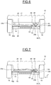
figure 6 représente une partie d'un train arrière d'un véhicule automobile selon un troisième mode de réalisation de l'invention ; - la
figure 7 représente la partie de train arrière selon lafigure 6 , après un effort de traction sur la barre de train ; et - la
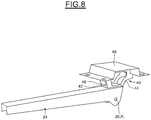
figure 8 est une vue de détails de l'organe de sûreté desfigures 6 et 7 . - Les
figures 1 à 7 représentent une partie d'un train arrière 10 d'un véhicule automobile. - La partie de train arrière 10 comprend une caisse 12, non démontable, un essieu arrière 14 reliant deux roues 16, 18, une barre de train 20 ou bielle comprenant une première extrémité 20a montée à rotation sur l'essieu 14 et une deuxième extrémité 20b montée à rotation sur un organe de sûreté 22 fixé à la caisse 12.
- La barre de train 20 peut être une barre de type « Panhard », consistant en une tige métallique rigide permettant la liaison entre une extrémité de l'essieu et la caisse et permettant un guidage latéral de l'essieu arrière.
- La barre de train 20 travaille en compression pour les chocs à la roue située du côté où ladite barre est fixée à l'essieu (situé à gauche sur les figures) et en traction pour les chocs à la roue située du côté où ladite barre est fixée à la caisse (situé à droite sur les figures).
- La partie de train arrière 10 comprend également une barre de renfort 24 montée en série avec la barre de train 20 et comprenant une première extrémité 24a montée à rotation sur la caisse 12, du côté où la barre de train est fixée à l'essieu, et une deuxième extrémité 24b montée à rotation sur la barre de train 20 et sur l'organe de sûreté 22, du côté où la barre de train est fixée à la caisse. La barre de renfort 24 est fixée de manière à travailler en direction opposée par rapport à la barre de train. En d'autres termes, lorsque la barre de train 20 travaille en traction, la barre de renfort 24 travaille en compression et inversement.
- Une telle barre de renfort 24 entre la caisse 12 et le côté opposé de la structure du soubassement permet de repousser une partie des efforts de traction en cas de choc latéral. Toutefois, une telle barre de renfort ne permet pas d'absorber toute l'énergie du choc latéral.
- La barre de renfort 24 présente, par exemple, une section en forme de U, comprenant deux perçages (non représentés) coaxiaux de réception d'un axe 26. La barre de renfort 24 est montée à rotation sur ledit axe 26. L'extrémité 20b de la barre de train 20 est montée à l'intérieur de la forme en U de ladite barre de renfort et à rotation autour dudit axe 26.
- Tel qu'illustré sur les
figures 1 à 3 , l'organe de sûreté 22 comprend une première extrémité 22a montée à rotation sur la caisse 12 par un premier axe 28 et une deuxième extrémité 22b montée à rotation sur l'axe 26 sur lequel sont montées à rotation les deuxièmes extrémités 20b, 24b de la barre de train 20 et de la barre de renfort 24. Le point de fixation P1 de la barre de train 20 et le point de fixation P2 de la barre de reprise d'effort 24 sur l'organe de sûreté 22 sont ici confondus. L'organe de sûreté 22 a ici la forme d'une bielle ou biellette articulée autour de deux liaisons pivots réalisées respectivement par un assemblage vissé ou par des douilles permettant d'assurer une liberté de déplacement selon la direction latérale du véhicule latéral des points de fixation P1, P2 commun à la barre de train 20 et la barre de renfort 24 en cas de choc latéral à la roue. - Grâce à ce déplacement latéral, en cas de choc latéral à la roue, le point de fixation P1, P2 commun aux deux barres peut se déplacer sans endommager l'organe de sûreté 22.
- Lors d'un effort de traction FT, par exemple, en cas de choc latéral, par exemple sur une roue arrière du côté de la caisse illustré sur la
figure 2 , la biellette 22 pivote par son extrémité 22a fixée à la caisse autour de l'axe 28, permettant au point de fixation commun P1, P2 de se déplacer angulairement autour dudit axe 28 engendrant le déplacement selon la direction latérale de la barre de train 20 et de la barre de renfort 24. La barre de renfort 24 absorbe ainsi l'énergie du choc latéral par flambage. Grâce à la biellette, la caisse 12 et la barre de train 20 ne sont pas endommagées. - Lors d'un effort en compression FC, illustré sur la
figure 3 , la barre de train 20 absorbe les efforts par flambage. La barre de renfort 24 et la biellette 22 ne bougent pas et la caisse 12 est ainsi préservée. - Les modes de réalisation illustrés sur les
figures 4 à 8 diffèrent du mode de réalisation illustré sur lesfigures 1 à 3 uniquement par la forme de l'organe de sûreté 30, 40. Les mêmes éléments portent les mêmes références. - Sur les
figures 4 à 8 , l'organe de sûreté 30, 40 se présente sous la forme d'une pièce mécanique déformable et ductile, c'est-à-dire qu'elle peut être tirée, étirée sans se rompre. - L'organe de sureté 30, 40 est configuré pour se déformer et se déplacer angulairement par rapport à son point de fixation à la caisse en cas de choc latéral à la roue sans détérioration de la caisse.
- Tel qu'illustré sur les
figures 4 et 5 , l'organe de sureté 30 ou chape déformable a une forme en L comprenant une première partie 32 fixée à la caisse 12 par exemple par des vis et une deuxième partie 34 formant un angle compris entre 45° et 90° par rapport à la première partie 32 et s'étendant vers l'essieu 14. L'extrémité 34a de la deuxième partie 34 de la chape déformable 30 comprend un perçage (non référencé) de réception de l'axe 26 sur lequel sont montées à rotation la barre de train 20 et la barre de renfort 24. L'axe 26 peut être sous la forme d'une vis. - Lors d'un effort de traction FT, par exemple, en cas de choc latéral, par exemple sur une roue arrière du côté de la caisse illustré sur la
figure 5 , la deuxième partie 34 de la chape déformable 30 pivote par son extrémité fixée à la première partie 32, permettant au point de fixation commun P1, P2 de se déplacer angulairement autour du même axe engendrant le déplacement selon la direction latérale de la barre de train 20 et de la barre de renfort 24. La barre de renfort 24 absorbe ainsi l'énergie du choc latéral par flambage. Grâce à la chape déformable, la caisse 12 et la barre de train 20 ne sont pas endommagées. - Lors d'un effort en compression FC, non représenté, la barre de train 20 absorbe les efforts par flambage. La barre de renfort 24 et la chape déformable 30 ne bougent pas et la caisse 12 est ainsi préservée.
- Tel qu'illustré en détails sur la
figure 8 , l'organe de sûreté 40 ou chape déformable fait partie de la barre de renfort 24. L'organe de sûreté 40 comprend une partie inférieure 42 fixée à la barre de renfort 24, par exemple, par soudage, deux flancs latéraux 44, 46 s'étendant vers la caisse 12 et une partie supérieure 48 fixée respectivement aux extrémités supérieures des flancs latéraux par exemple par soudage, et à la caisse, par exemple par des moyens de visseries. - L'organe de sûreté est réalisé à partir de tôles métalliques embouties et usinées pour enlever de la matière afin de lui permettre d'être ductile, c'est-à-dire de se déformer sans se rompre lors d'un choc latéral à la roue.
- Dans ce mode de réalisation, la barre de train 20 est fixée à l'ensemble comprenant la barre de renfort 24 et la chape déformable 40.
- Lors d'un effort de traction FT, par exemple, en cas de choc latéral, par exemple sur une roue arrière du côté de la caisse illustré sur la
figure 7 , les flancs latéraux 44, 46 de la chape déformable 40 se déforment permettant au point de fixation P1 de la barre de train 20 de se déplacer angulairement engendrant le déplacement selon la direction latéral de la barre de train 20. L'ensemble barre de renfort 24/chape déformable 40 absorbent ainsi l'énergie du choc latéral respectivement par flambage et déformation. Grâce à la chape déformable, la caisse 12 et la barre de train 20 ne sont pas endommagées. - Lors d'un effort en compression FC, non représenté, la barre de train 20 absorbe les efforts par flambage. La barre de renfort 24 et la chape déformable 40 ne bougent pas et la caisse 12 est ainsi préservée.
- Dans tous les modes de réalisation, l'organe de sûreté 22, 30, 40 et la barre de renfort 24 sont fixés respectivement à la caisse par des vis, des douilles ou de liaisons rotules, ou tout autre moyen permettant à ces pièces d'être interchangeables et ainsi de limiter les frais de réparation.
- Dans tous les modes de réalisation, l'organe de sûreté 22, 30, 40 est réalisé en matériau fortement ductile, tel que par exemple, de l'acier, de l'aluminium avec un allongement à la rupture élevé ou tout autre matériau permettant d'obtenir de fortes déformations sans risque de rupture notamment pour des raisons de sécurité. L'organe de sûreté 22, 30, 40 est par exemple réalisé en acier HE450M.
- Ainsi, grâce à l'invention, l'organe de sûreté intervient comme une pièce fusible lorsque l'énergie d'un choc latéral est transmise à une roue arrière du véhicule automobile. Sa déformation, ainsi que la déformation de la barre de renfort permettent de générer une nuisance sonore alertant le conducteur du véhicule qu'un choc latéral endommageant à la roue s'est produit.
Claims (10)
- Train arrière de véhicule automobile comprenant une caisse (12), un essieu arrière (14) reliant deux roues (16, 18), une barre de train (20) comprenant une première extrémité (20a) montée à rotation sur ledit essieu, caractérisé en ce qu'il comprend un organe de sûreté (22, 30, 40) fixé respectivement à la caisse (12) du véhicule et à une deuxième extrémité (20b) de la barre de train, ledit organe de sûreté étant configuré pour permettre le déplacement angulaire du point de fixation (P1) de la barre de train (20) par rapport audit organe lors d'un choc à la roue située du côté où ladite barre est fixée audit organe.
- Train arrière selon la revendication 1, comprenant une barre de renfort (24) comportant une première extrémité (24a) montée à rotation sur la caisse (12), du côté où la barre de train (20) est fixée à l'essieu (14), et une deuxième extrémité (24b) fixée à l'organe de sûreté (22, 30, 40).
- Train arrière selon la revendication 2, dans lequel la barre de renfort (24) présente une section en forme de U comprenant deux perçages coaxiaux de réception d'un axe (26), la barre de renfort (24) et la barre de train (20) étant montées à rotation autour dudit axe (26).
- Train arrière selon la revendication 3, dans lequel l'organe de sûreté (22, 30) comprend une première extrémité (22a, 30a) fixée à la caisse (12) et une deuxième extrémité (22b, 30b) recevant ledit axe (26).
- Train arrière selon l'une quelconque des revendications précédentes, dans lequel l'organe de sûreté (22) a la forme d'une biellette articulée autour de deux liaisons pivots permettant d'assurer une liberté de déplacement selon la direction latérale du véhicule latéral du point de fixation (P1, P2) commun à la barre de train (20) et la barre de renfort (24) lors d'un choc à la roue située du côté où ladite barre est fixée audit organe.
- Train arrière selon l'une quelconque des revendications précédentes, dans lequel l'organe de sûreté (30, 40) est une pièce mécanique déformable et ductile, configurée pour se déformer et se déplacer angulairement par rapport à son point de fixation à la caisse (12) en cas de choc latéral à la roue.
- Train arrière selon la revendication 6, dans lequel l'organe de sûreté (30) a une forme en L comprenant une première partie (32) fixée à la caisse (12) et une deuxième partie (34) formant un angle compris entre 45° et 90° par rapport à la première partie (32) et s'étendant vers l'essieu (14).
- Train arrière selon la revendication 6, dans lequel l'organe de sûreté (40) fait partie de la barre de renfort (24).
- Train arrière selon la revendication 8, dans lequel l'organe de sûreté (40) comprend une partie inférieure (42) fixée à la barre de renfort (24), deux flancs latéraux (44, 46) s'étendant vers la caisse (12) et une partie supérieure (48) fixée respectivement aux extrémités supérieures des flancs latéraux et à la caisse.
- Véhicule automobile comprenant une caisse (12), un train arrière (10) selon l'une quelconque des revendications précédentes.
Applications Claiming Priority (1)
| Application Number | Priority Date | Filing Date | Title |
|---|---|---|---|
| FR1756287A FR3068669B1 (fr) | 2017-07-04 | 2017-07-04 | Train arriere de vehicule automobile comprenant des moyens d'absorption de l'energie d'un choc lateral |
Publications (2)
| Publication Number | Publication Date |
|---|---|
| EP3424757A1 true EP3424757A1 (fr) | 2019-01-09 |
| EP3424757B1 EP3424757B1 (fr) | 2021-02-17 |
Family
ID=59699925
Family Applications (1)
| Application Number | Title | Priority Date | Filing Date |
|---|---|---|---|
| EP18181255.3A Active EP3424757B1 (fr) | 2017-07-04 | 2018-07-02 | Train arrière de véhicule automobile comprenant des moyens d'absorption de l'énergie d'un choc latéral |
Country Status (2)
| Country | Link |
|---|---|
| EP (1) | EP3424757B1 (fr) |
| FR (1) | FR3068669B1 (fr) |
Citations (4)
| Publication number | Priority date | Publication date | Assignee | Title |
|---|---|---|---|---|
| JPH0379410A (ja) * | 1989-08-23 | 1991-04-04 | Nissan Motor Co Ltd | 車軸式懸架装置 |
| JPH11165518A (ja) * | 1997-12-05 | 1999-06-22 | Nissan Motor Co Ltd | リヤサスペンションのリンク取付け構造 |
| EP0947362A2 (fr) * | 1998-03-30 | 1999-10-06 | Mazda Motor Corporation | Dispositif de suspension arrière pour véhicule automobile |
| CN104442272A (zh) * | 2014-11-21 | 2015-03-25 | 重庆永淳新能源科技有限公司 | 电动汽车防侧撞后桥结构 |
-
2017
- 2017-07-04 FR FR1756287A patent/FR3068669B1/fr active Active
-
2018
- 2018-07-02 EP EP18181255.3A patent/EP3424757B1/fr active Active
Patent Citations (4)
| Publication number | Priority date | Publication date | Assignee | Title |
|---|---|---|---|---|
| JPH0379410A (ja) * | 1989-08-23 | 1991-04-04 | Nissan Motor Co Ltd | 車軸式懸架装置 |
| JPH11165518A (ja) * | 1997-12-05 | 1999-06-22 | Nissan Motor Co Ltd | リヤサスペンションのリンク取付け構造 |
| EP0947362A2 (fr) * | 1998-03-30 | 1999-10-06 | Mazda Motor Corporation | Dispositif de suspension arrière pour véhicule automobile |
| CN104442272A (zh) * | 2014-11-21 | 2015-03-25 | 重庆永淳新能源科技有限公司 | 电动汽车防侧撞后桥结构 |
Also Published As
| Publication number | Publication date |
|---|---|
| FR3068669B1 (fr) | 2019-11-22 |
| FR3068669A1 (fr) | 2019-01-11 |
| EP3424757B1 (fr) | 2021-02-17 |
Similar Documents
| Publication | Publication Date | Title |
|---|---|---|
| CA2121995C (fr) | Dispositif d'amortissement de choc | |
| FR2747633A1 (fr) | Vehicule ferroviaire a cabine de conduite comportant une structure absorbeuse d'energie a deformation progressive | |
| EP2188157B1 (fr) | Impacteur de choc pour groupe motopropulseur automobile | |
| EP2934953A1 (fr) | Dispositif d'absorption de chocs pour la structure avant ou arriere d'un véhicule | |
| EP2303631A1 (fr) | Siege pour vehicule blinde | |
| EP1827943B1 (fr) | Dispositif absorbeur de chocs pour vehicule ferroviaire | |
| WO2019158835A1 (fr) | Vehicule comprenant au moins un deviateur associe a un absorbeur pour repondre a un choc frontal de faible recouvrement | |
| FR3068669B1 (fr) | Train arriere de vehicule automobile comprenant des moyens d'absorption de l'energie d'un choc lateral | |
| FR3092067A1 (fr) | Berceau moteur pour véhicule automobile et véhicule comportant un tel berceau | |
| EP1106467A1 (fr) | Dispositif de déformation contrôlée sous efforts ou d'absorption d'énergie par déformation, notamment déflecteur d'obstacles pour véhicule ferroviaire | |
| EP2130717B1 (fr) | Systéme pour limiter des dommages susceptibles, en cas de choc, d'être causés par une optique à au moins un organe d'un véhicule automobile | |
| EP3362334B1 (fr) | Composant de structure de véhicule automobile, et section de voie basse avant comprenant un tel composant | |
| EP3085554A1 (fr) | Ensemble de pare-chocs comportant un ecrou de remorquage et vehicule comportant un tel ensemble de pare-chocs | |
| EP3427981B1 (fr) | Train arrière de véhicule automobile comprenant des moyens d'absorption de l'énergie d'un choc arrière | |
| FR3055583B1 (fr) | Train arriere de vehicule automobile comprenant des moyens d'absorption de l'energie d'un choc lateral | |
| FR3009255A1 (fr) | Voie basse pour vehicule automobile | |
| FR3093674A1 (fr) | Train de véhicule automobile comportant un bras de suspension assemblé comportant un organe de sureté fusible | |
| FR3071808B1 (fr) | Pied avant renforce de vehicule | |
| FR3022603A1 (fr) | Dispositif absorbeur d'energie et vehicule correspondant | |
| FR3159366A1 (fr) | Dispositif d’absorption de chocs renforcé en traction. | |
| FR3137649A1 (fr) | Structure avant de véhicule automobile et véhicule automobile comportant une telle structure avant | |
| WO2010010276A2 (fr) | Element de carrosserie avec moyens de limitation du recul de cet element lors d'un choc sur celui-ci | |
| FR3030428A1 (fr) | Berceau d'un vehicule automobile | |
| WO2019122310A1 (fr) | Dispositif anti-recul d'un élément de véhicule automobile en cas de choc avant | |
| EP1874592A2 (fr) | Structure de l'avant d'un vehicule automobile |
Legal Events
| Date | Code | Title | Description |
|---|---|---|---|
| PUAI | Public reference made under article 153(3) epc to a published international application that has entered the european phase |
Free format text: ORIGINAL CODE: 0009012 |
|
| STAA | Information on the status of an ep patent application or granted ep patent |
Free format text: STATUS: THE APPLICATION HAS BEEN PUBLISHED |
|
| AK | Designated contracting states |
Kind code of ref document: A1 Designated state(s): AL AT BE BG CH CY CZ DE DK EE ES FI FR GB GR HR HU IE IS IT LI LT LU LV MC MK MT NL NO PL PT RO RS SE SI SK SM TR |
|
| AX | Request for extension of the european patent |
Extension state: BA ME |
|
| STAA | Information on the status of an ep patent application or granted ep patent |
Free format text: STATUS: REQUEST FOR EXAMINATION WAS MADE |
|
| 17P | Request for examination filed |
Effective date: 20190625 |
|
| RBV | Designated contracting states (corrected) |
Designated state(s): AL AT BE BG CH CY CZ DE DK EE ES FI FR GB GR HR HU IE IS IT LI LT LU LV MC MK MT NL NO PL PT RO RS SE SI SK SM TR |
|
| GRAP | Despatch of communication of intention to grant a patent |
Free format text: ORIGINAL CODE: EPIDOSNIGR1 |
|
| STAA | Information on the status of an ep patent application or granted ep patent |
Free format text: STATUS: GRANT OF PATENT IS INTENDED |
|
| INTG | Intention to grant announced |
Effective date: 20200603 |
|
| GRAS | Grant fee paid |
Free format text: ORIGINAL CODE: EPIDOSNIGR3 |
|
| GRAA | (expected) grant |
Free format text: ORIGINAL CODE: 0009210 |
|
| STAA | Information on the status of an ep patent application or granted ep patent |
Free format text: STATUS: THE PATENT HAS BEEN GRANTED |
|
| AK | Designated contracting states |
Kind code of ref document: B1 Designated state(s): AL AT BE BG CH CY CZ DE DK EE ES FI FR GB GR HR HU IE IS IT LI LT LU LV MC MK MT NL NO PL PT RO RS SE SI SK SM TR |
|
| REG | Reference to a national code |
Ref country code: GB Ref legal event code: FG4D Free format text: NOT ENGLISH |
|
| REG | Reference to a national code |
Ref country code: CH Ref legal event code: EP |
|
| REG | Reference to a national code |
Ref country code: DE Ref legal event code: R096 Ref document number: 602018012534 Country of ref document: DE |
|
| REG | Reference to a national code |
Ref country code: AT Ref legal event code: REF Ref document number: 1361017 Country of ref document: AT Kind code of ref document: T Effective date: 20210315 |
|
| REG | Reference to a national code |
Ref country code: IE Ref legal event code: FG4D Free format text: LANGUAGE OF EP DOCUMENT: FRENCH |
|
| REG | Reference to a national code |
Ref country code: LT Ref legal event code: MG9D |
|
| REG | Reference to a national code |
Ref country code: NL Ref legal event code: MP Effective date: 20210217 |
|
| PG25 | Lapsed in a contracting state [announced via postgrant information from national office to epo] |
Ref country code: FI Free format text: LAPSE BECAUSE OF FAILURE TO SUBMIT A TRANSLATION OF THE DESCRIPTION OR TO PAY THE FEE WITHIN THE PRESCRIBED TIME-LIMIT Effective date: 20210217 Ref country code: GR Free format text: LAPSE BECAUSE OF FAILURE TO SUBMIT A TRANSLATION OF THE DESCRIPTION OR TO PAY THE FEE WITHIN THE PRESCRIBED TIME-LIMIT Effective date: 20210518 Ref country code: HR Free format text: LAPSE BECAUSE OF FAILURE TO SUBMIT A TRANSLATION OF THE DESCRIPTION OR TO PAY THE FEE WITHIN THE PRESCRIBED TIME-LIMIT Effective date: 20210217 Ref country code: BG Free format text: LAPSE BECAUSE OF FAILURE TO SUBMIT A TRANSLATION OF THE DESCRIPTION OR TO PAY THE FEE WITHIN THE PRESCRIBED TIME-LIMIT Effective date: 20210517 Ref country code: NO Free format text: LAPSE BECAUSE OF FAILURE TO SUBMIT A TRANSLATION OF THE DESCRIPTION OR TO PAY THE FEE WITHIN THE PRESCRIBED TIME-LIMIT Effective date: 20210517 Ref country code: PT Free format text: LAPSE BECAUSE OF FAILURE TO SUBMIT A TRANSLATION OF THE DESCRIPTION OR TO PAY THE FEE WITHIN THE PRESCRIBED TIME-LIMIT Effective date: 20210617 Ref country code: LT Free format text: LAPSE BECAUSE OF FAILURE TO SUBMIT A TRANSLATION OF THE DESCRIPTION OR TO PAY THE FEE WITHIN THE PRESCRIBED TIME-LIMIT Effective date: 20210217 |
|
| REG | Reference to a national code |
Ref country code: AT Ref legal event code: MK05 Ref document number: 1361017 Country of ref document: AT Kind code of ref document: T Effective date: 20210217 |
|
| PG25 | Lapsed in a contracting state [announced via postgrant information from national office to epo] |
Ref country code: NL Free format text: LAPSE BECAUSE OF FAILURE TO SUBMIT A TRANSLATION OF THE DESCRIPTION OR TO PAY THE FEE WITHIN THE PRESCRIBED TIME-LIMIT Effective date: 20210217 Ref country code: PL Free format text: LAPSE BECAUSE OF FAILURE TO SUBMIT A TRANSLATION OF THE DESCRIPTION OR TO PAY THE FEE WITHIN THE PRESCRIBED TIME-LIMIT Effective date: 20210217 Ref country code: LV Free format text: LAPSE BECAUSE OF FAILURE TO SUBMIT A TRANSLATION OF THE DESCRIPTION OR TO PAY THE FEE WITHIN THE PRESCRIBED TIME-LIMIT Effective date: 20210217 Ref country code: RS Free format text: LAPSE BECAUSE OF FAILURE TO SUBMIT A TRANSLATION OF THE DESCRIPTION OR TO PAY THE FEE WITHIN THE PRESCRIBED TIME-LIMIT Effective date: 20210217 Ref country code: SE Free format text: LAPSE BECAUSE OF FAILURE TO SUBMIT A TRANSLATION OF THE DESCRIPTION OR TO PAY THE FEE WITHIN THE PRESCRIBED TIME-LIMIT Effective date: 20210217 |
|
| PG25 | Lapsed in a contracting state [announced via postgrant information from national office to epo] |
Ref country code: IS Free format text: LAPSE BECAUSE OF FAILURE TO SUBMIT A TRANSLATION OF THE DESCRIPTION OR TO PAY THE FEE WITHIN THE PRESCRIBED TIME-LIMIT Effective date: 20210617 |
|
| PG25 | Lapsed in a contracting state [announced via postgrant information from national office to epo] |
Ref country code: EE Free format text: LAPSE BECAUSE OF FAILURE TO SUBMIT A TRANSLATION OF THE DESCRIPTION OR TO PAY THE FEE WITHIN THE PRESCRIBED TIME-LIMIT Effective date: 20210217 Ref country code: CZ Free format text: LAPSE BECAUSE OF FAILURE TO SUBMIT A TRANSLATION OF THE DESCRIPTION OR TO PAY THE FEE WITHIN THE PRESCRIBED TIME-LIMIT Effective date: 20210217 Ref country code: AT Free format text: LAPSE BECAUSE OF FAILURE TO SUBMIT A TRANSLATION OF THE DESCRIPTION OR TO PAY THE FEE WITHIN THE PRESCRIBED TIME-LIMIT Effective date: 20210217 Ref country code: SM Free format text: LAPSE BECAUSE OF FAILURE TO SUBMIT A TRANSLATION OF THE DESCRIPTION OR TO PAY THE FEE WITHIN THE PRESCRIBED TIME-LIMIT Effective date: 20210217 |
|
| REG | Reference to a national code |
Ref country code: DE Ref legal event code: R097 Ref document number: 602018012534 Country of ref document: DE |
|
| PG25 | Lapsed in a contracting state [announced via postgrant information from national office to epo] |
Ref country code: RO Free format text: LAPSE BECAUSE OF FAILURE TO SUBMIT A TRANSLATION OF THE DESCRIPTION OR TO PAY THE FEE WITHIN THE PRESCRIBED TIME-LIMIT Effective date: 20210217 Ref country code: DK Free format text: LAPSE BECAUSE OF FAILURE TO SUBMIT A TRANSLATION OF THE DESCRIPTION OR TO PAY THE FEE WITHIN THE PRESCRIBED TIME-LIMIT Effective date: 20210217 Ref country code: SK Free format text: LAPSE BECAUSE OF FAILURE TO SUBMIT A TRANSLATION OF THE DESCRIPTION OR TO PAY THE FEE WITHIN THE PRESCRIBED TIME-LIMIT Effective date: 20210217 |
|
| PLBE | No opposition filed within time limit |
Free format text: ORIGINAL CODE: 0009261 |
|
| STAA | Information on the status of an ep patent application or granted ep patent |
Free format text: STATUS: NO OPPOSITION FILED WITHIN TIME LIMIT |
|
| 26N | No opposition filed |
Effective date: 20211118 |
|
| PG25 | Lapsed in a contracting state [announced via postgrant information from national office to epo] |
Ref country code: AL Free format text: LAPSE BECAUSE OF FAILURE TO SUBMIT A TRANSLATION OF THE DESCRIPTION OR TO PAY THE FEE WITHIN THE PRESCRIBED TIME-LIMIT Effective date: 20210217 Ref country code: ES Free format text: LAPSE BECAUSE OF FAILURE TO SUBMIT A TRANSLATION OF THE DESCRIPTION OR TO PAY THE FEE WITHIN THE PRESCRIBED TIME-LIMIT Effective date: 20210217 |
|
| PG25 | Lapsed in a contracting state [announced via postgrant information from national office to epo] |
Ref country code: SI Free format text: LAPSE BECAUSE OF FAILURE TO SUBMIT A TRANSLATION OF THE DESCRIPTION OR TO PAY THE FEE WITHIN THE PRESCRIBED TIME-LIMIT Effective date: 20210217 |
|
| REG | Reference to a national code |
Ref country code: CH Ref legal event code: PL |
|
| PG25 | Lapsed in a contracting state [announced via postgrant information from national office to epo] |
Ref country code: MC Free format text: LAPSE BECAUSE OF FAILURE TO SUBMIT A TRANSLATION OF THE DESCRIPTION OR TO PAY THE FEE WITHIN THE PRESCRIBED TIME-LIMIT Effective date: 20210217 |
|
| REG | Reference to a national code |
Ref country code: BE Ref legal event code: MM Effective date: 20210731 |
|
| PG25 | Lapsed in a contracting state [announced via postgrant information from national office to epo] |
Ref country code: LI Free format text: LAPSE BECAUSE OF NON-PAYMENT OF DUE FEES Effective date: 20210731 Ref country code: IT Free format text: LAPSE BECAUSE OF FAILURE TO SUBMIT A TRANSLATION OF THE DESCRIPTION OR TO PAY THE FEE WITHIN THE PRESCRIBED TIME-LIMIT Effective date: 20210217 Ref country code: CH Free format text: LAPSE BECAUSE OF NON-PAYMENT OF DUE FEES Effective date: 20210731 |
|
| PG25 | Lapsed in a contracting state [announced via postgrant information from national office to epo] |
Ref country code: IS Free format text: LAPSE BECAUSE OF FAILURE TO SUBMIT A TRANSLATION OF THE DESCRIPTION OR TO PAY THE FEE WITHIN THE PRESCRIBED TIME-LIMIT Effective date: 20210617 Ref country code: LU Free format text: LAPSE BECAUSE OF NON-PAYMENT OF DUE FEES Effective date: 20210702 |
|
| PG25 | Lapsed in a contracting state [announced via postgrant information from national office to epo] |
Ref country code: IE Free format text: LAPSE BECAUSE OF NON-PAYMENT OF DUE FEES Effective date: 20210702 Ref country code: BE Free format text: LAPSE BECAUSE OF NON-PAYMENT OF DUE FEES Effective date: 20210731 |
|
| PG25 | Lapsed in a contracting state [announced via postgrant information from national office to epo] |
Ref country code: CY Free format text: LAPSE BECAUSE OF FAILURE TO SUBMIT A TRANSLATION OF THE DESCRIPTION OR TO PAY THE FEE WITHIN THE PRESCRIBED TIME-LIMIT Effective date: 20210217 |
|
| P01 | Opt-out of the competence of the unified patent court (upc) registered |
Effective date: 20230608 |
|
| PG25 | Lapsed in a contracting state [announced via postgrant information from national office to epo] |
Ref country code: HU Free format text: LAPSE BECAUSE OF FAILURE TO SUBMIT A TRANSLATION OF THE DESCRIPTION OR TO PAY THE FEE WITHIN THE PRESCRIBED TIME-LIMIT; INVALID AB INITIO Effective date: 20180702 |
|
| PG25 | Lapsed in a contracting state [announced via postgrant information from national office to epo] |
Ref country code: MK Free format text: LAPSE BECAUSE OF FAILURE TO SUBMIT A TRANSLATION OF THE DESCRIPTION OR TO PAY THE FEE WITHIN THE PRESCRIBED TIME-LIMIT Effective date: 20210217 |
|
| PG25 | Lapsed in a contracting state [announced via postgrant information from national office to epo] |
Ref country code: TR Free format text: LAPSE BECAUSE OF FAILURE TO SUBMIT A TRANSLATION OF THE DESCRIPTION OR TO PAY THE FEE WITHIN THE PRESCRIBED TIME-LIMIT Effective date: 20210217 |
|
| PG25 | Lapsed in a contracting state [announced via postgrant information from national office to epo] |
Ref country code: MT Free format text: LAPSE BECAUSE OF FAILURE TO SUBMIT A TRANSLATION OF THE DESCRIPTION OR TO PAY THE FEE WITHIN THE PRESCRIBED TIME-LIMIT Effective date: 20210217 |
|
| PGFP | Annual fee paid to national office [announced via postgrant information from national office to epo] |
Ref country code: DE Payment date: 20250722 Year of fee payment: 8 |
|
| PGFP | Annual fee paid to national office [announced via postgrant information from national office to epo] |
Ref country code: GB Payment date: 20250722 Year of fee payment: 8 |
|
| PGFP | Annual fee paid to national office [announced via postgrant information from national office to epo] |
Ref country code: FR Payment date: 20250725 Year of fee payment: 8 |