EP3424748A1 - Fahrzeugrad - Google Patents
Fahrzeugrad Download PDFInfo
- Publication number
- EP3424748A1 EP3424748A1 EP18167485.4A EP18167485A EP3424748A1 EP 3424748 A1 EP3424748 A1 EP 3424748A1 EP 18167485 A EP18167485 A EP 18167485A EP 3424748 A1 EP3424748 A1 EP 3424748A1
- Authority
- EP
- European Patent Office
- Prior art keywords
- wall part
- wheel
- wheel disc
- vehicle wheel
- rim
- Prior art date
- Legal status (The legal status is an assumption and is not a legal conclusion. Google has not performed a legal analysis and makes no representation as to the accuracy of the status listed.)
- Granted
Links
Images

Classifications
-
- B—PERFORMING OPERATIONS; TRANSPORTING
- B60—VEHICLES IN GENERAL
- B60B—VEHICLE WHEELS; CASTORS; AXLES FOR WHEELS OR CASTORS; INCREASING WHEEL ADHESION
- B60B3/00—Disc wheels, i.e. wheels with load-supporting disc body
- B60B3/14—Attaching disc body to hub ; Wheel adapters
- B60B3/16—Attaching disc body to hub ; Wheel adapters by bolts or the like
-
- B—PERFORMING OPERATIONS; TRANSPORTING
- B60—VEHICLES IN GENERAL
- B60B—VEHICLE WHEELS; CASTORS; AXLES FOR WHEELS OR CASTORS; INCREASING WHEEL ADHESION
- B60B3/00—Disc wheels, i.e. wheels with load-supporting disc body
- B60B3/04—Disc wheels, i.e. wheels with load-supporting disc body with a single disc body not integral with rim, i.e. disc body and rim being manufactured independently and then permanently attached to each other in a second step, e.g. by welding
- B60B3/041—Disc wheels, i.e. wheels with load-supporting disc body with a single disc body not integral with rim, i.e. disc body and rim being manufactured independently and then permanently attached to each other in a second step, e.g. by welding characterised by the attachment of rim to wheel disc
- B60B3/045—Disc wheels, i.e. wheels with load-supporting disc body with a single disc body not integral with rim, i.e. disc body and rim being manufactured independently and then permanently attached to each other in a second step, e.g. by welding characterised by the attachment of rim to wheel disc characterised by the attachment portions
-
- B—PERFORMING OPERATIONS; TRANSPORTING
- B60—VEHICLES IN GENERAL
- B60B—VEHICLE WHEELS; CASTORS; AXLES FOR WHEELS OR CASTORS; INCREASING WHEEL ADHESION
- B60B19/00—Wheels not otherwise provided for or having characteristics specified in one of the subgroups of this group
- B60B19/10—Wheels not otherwise provided for or having characteristics specified in one of the subgroups of this group with cooling fins
-
- B—PERFORMING OPERATIONS; TRANSPORTING
- B60—VEHICLES IN GENERAL
- B60B—VEHICLE WHEELS; CASTORS; AXLES FOR WHEELS OR CASTORS; INCREASING WHEEL ADHESION
- B60B3/00—Disc wheels, i.e. wheels with load-supporting disc body
- B60B3/002—Disc wheels, i.e. wheels with load-supporting disc body characterised by the shape of the disc
- B60B3/007—Disc wheels, i.e. wheels with load-supporting disc body characterised by the shape of the disc in the intermediate section
Definitions
- the invention relates to a vehicle wheel, comprising a rim tape and a wheel disc, wherein the wheel disc has a center hole for receiving the wheel hub concentrically arranged around the bolt circle arrangement of stud bolts and a Riempel, the wheel hub in one of the hub facing inner wall part and a rim tape subdivided facing outer wall part, wherein in the outer wall part a concentric ventilation hole row is provided.
- the motor vehicle wheel is a safety component and must therefore be able to withstand the high mechanical and dynamic cyclic stresses during operation.
- Conventional motor vehicle wheels in steel-sheet construction consist of a wheel disc, which ensures the connection to the wheel hub and the rim tape which receives the tire.
- the wheel components made of steel are nowadays produced without exception by cold forming in a multi-stage process (deep-drawing, flow-forming, profiling).
- the wheel discs are manufactured on progressive presses with up to eleven stages and the rims by rolling process or profiling.
- Hot rolled and pickled strip material made of microalloyed structural steels and dual-phase steels with a tensile strength of 400-600 MPa is used almost exclusively.
- Joining techniques often involve MIG welding.
- Conventional steel wheels have a series of circular vent holes on the outer wall surface relative to the cradle.
- the invention is based on the object of specifying a motor vehicle wheel made of sheet steel for passenger vehicles, which is characterized by a low weight, lower costs compared to aluminum wheels, high design freedom and attractiveness at the same time high Durability and safety.
- the object is achieved according to the invention with a vehicle wheel having a rim tape and a wheel disc, wherein the wheel disc has a center hole for receiving the wheel hub concentrically arranged around the bolt circle arrangement of stud bolts, as well as a Riempel, the wheel hub in one of the hub facing inner wall part and subdivided into the rim strip outer wall portion, wherein in the outer wall portion a concentric ventilation hole row is provided, characterized in that the wheel is executed with a circumferential flange for connection to the rim and made of a metallic material, in particular steel and that in the inner wall part the wheel disc is formed at least one further concentric ventilation hole row.
- the individual ventilation holes in the inner wall part may be radially aligned relative to the outer wall part or arranged in a gap.
- An advantage of the voltage optimization is also an embodiment of the vehicle wheel in which the individual ventilation holes in the inner wall portion relative to the outer wall portion are arranged offset on a line or at an angle to each other.
- the ventilation holes have a circular or oval shape or are made from wheel center to wheel outside conical with a continuously variable and / or discontinuous cross-section.
- the design of the ventilation holes can serve on the one hand to cover different designs and visual appearances, on the other hand, the arrangement and design of the ventilation holes, individually, optimized for different requirements, performance values and voltages.
- the wheel disc is designed as TailoredWeldedBlank and / or TailoredRolledBlank, wherein the inner wall part has different properties than the outer wall part, in particular by different materials and / or different material thicknesses.
- different required strengths and thicknesses can be used, which lead, for example, in a load case to a voltage reduction and / or better stress distribution.
- the conventional vehicle wheel shown has a rim tape 1 and a wheel disc formed by a cradle 2, that is, a rigidity shaft, in an inner wall surface 7 extending between the center hole 3 and the cradle 2, and an outer wall surface 6 extending between cuvettes 2 and rim tape 1 runs, is divided.
- a hole circle 4 surrounded the center hole 3 is shown, which serves to receive the studs, which connect the wheel or more precisely, the wheel disc with the hub (not shown).
Landscapes
- Engineering & Computer Science (AREA)
- Mechanical Engineering (AREA)
- Body Structure For Vehicles (AREA)
- Heat Treatment Of Articles (AREA)
Abstract
Description
- Die Erfindung betrifft ein Fahrzeugrad, aufweisend ein Felgenband und eine Radschüssel, wobei die Radschüssel ein Mittenloch zur Aufnahme der Radnabe mit konzentrisch darum angeordnetem Lochkreis zur Anordnung der Stehbolzen sowie einen Kümpel aufweist, der die Radschüssel in einen der Nabe zugekehrten inneren Wandteil und einen dem Felgenband zugekehrten äußeren Wandteil unterteilt, wobei im äußeren Wandteil eine konzentrische Belüftungslochreihe vorgesehen ist.
- Das Kraftfahrzeugrad ist ein Sicherheitsbauteil und muss daher die hohen mechanischen und dynamischen Wechselbeanspruchungen im Betrieb dauerfest aufnehmen können. Konventionelle Kraftfahrzeugräder in Stahl-Blechbauweise bestehen aus einer Radschüssel, die die Verbindung zur Radnabe sicherstellt und dem Felgenband, welches den Reifen aufnimmt.
- Die Radkomponenten aus Stahl werden heutzutage ausnahmslos durch Kaltumformung im Mehrstufenverfahren (Tiefziehen, Drückwalzen, Profilieren) hergestellt. Die Radschüsseln werden auf Stufenpressen mit bis zu elf Stufen gefertigt und die Felgen durch Rollverfahren bzw. Profilieren. Dabei kommt fast ausschließlich warmgewalztes und gebeiztes Bandmaterial aus mikrolegierten Baustählen und Dualphasen-Stählen mit einer Zugfestigkeit von 400 - 600 MPa zum Einsatz. Als Fügetechnik wird häufig eine MIG - Schweißung vorgesehen. Konventionelle Stahlräder weisen eine Reihe kreisrunder Belüftungslöcher auf der - bezogen auf den Kümpel - äußeren Wandfläche auf.
- Neben Lebensdauer, Steifigkeit und Gewicht der Räder spielt das Design eine wesentliche Rolle. Die Designfreiheit und Attraktivität konventioneller Stahl-Räder ist mit konventionellen Bauweisen und Werkstoffen stark eingeschränkt. Im Rahmen der Elektromobilität ist es äußerst attraktiv, leichte Fahrzeugräder zu produzieren. Kleinere Fahrzeuge ermöglichen schmalere Räder sowie geringere Radlasten. Letzteres führt zu neuen geometrischen Ausführungen.
- Der Erfindung liegt nun die Aufgabe zugrunde, ein Kraftfahrzeugrad aus Stahlblech für Personenfahrzeuge anzugeben, welches sich durch ein geringes Gewicht, geringere Kosten im Vergleich zu Aluminiumrädern, hohe Gestaltungsfreiheit und Attraktivität bei gleichzeitig hoher Betriebsfestigkeit und Sicherheit auszeichnet.
- Die Aufgabe wird erfindungsgemäß gelöst mit einem Fahrzeugrad aufweisend ein Felgenband und eine Radschüssel, wobei die Radschüssel ein Mittenloch zur Aufnahme der Radnabe mit konzentrisch darum angeordnetem Lochkreis zur Anordnung der Stehbolzen, sowie einen Kümpel aufweist, der die Radschüssel in einen der Nabe zugekehrten inneren Wandteil und einen dem Felgenband zugekehrten äußeren Wandteil unterteilt, wobei im äußeren Wandteil eine konzentrische Belüftungslochreihe vorgesehen ist, dadurch, dass die Radschüssel mit einem umlaufenden Flansch zur Anbindung an die Felge ausgeführt ist und aus einem metallischen Werkstoff, insbesondere aus Stahl besteht und dass in dem inneren Wandteil der Radschüssel mindestens eine weitere konzentrische Belüftungslochreihe ausgebildet ist.
- Die Radschüsseln herkömmlicher Stahlräder besitzen auf der - bezogen auf den Kümpel - äußeren Wandfläche Belüftungslöcher, vorzugsweise in Form einer kreisrunden Aussparung. Diese dienen der Hitzeabfuhr, entstanden durch Bremsvorgänge. Bisher ist es aufgrund der Belastungen auf das Rad und der sehr hoher Spannungswerte nur möglich, Belüftungslöcher in dem äußeren Wandteil der Radschüssel, also auf der Kümpelaußenseite, anzubringen, d.h. der dem Felgenband zugewandten Wandfläche - bezogen auf den Kümpel.
- Durch die Reduzierung des Fahrzeuggewichtes und der damit einhergehenden Reduzierung der Radlasten besteht die Möglichkeit, auch auf der Kümpelinnenseite, also im inneren Wandteil der Radschüssel zwischen dem das Mittenloch umgebenden Lockkreis und Kümpel, Belüftungslöcher einzubringen.
- Die besondere Ausbildung und Anordnung der Belüftungslöcher wird dazu benutzt, die im Belastungsfall auftretenden Spannungen einzustellen und zu optimieren.
So können, gemäß einer Ausgestaltung des Fahrzeugrades, die einzelnen Belüftungslöcher im inneren Wandteil bezogen auf den äußeren Wandteil radial ausgerichtet oder auf Lücke angeordnet sein. - Vorteilhaft für die Spannungsoptimierung ist auch eine Ausgestaltung des Fahrzeugrades bei der die einzelnen Belüftungslöcher im inneren Wandteil bezogen auf den äußeren Wandteil auf einer Linie oder in einem Winkel zueinander versetzt angeordnet sind.
- Gemäß einer weiteren Ausgestaltung des Fahrzeugrades weisen die Belüftungslöcher eine kreisrunde oder ovale Form auf oder sind von Radmitte zu Radaußenseite konisch mit kontinuierlich veränderlichem und/oder diskontinuierlichem Querschnitt ausgeführt. Die Ausgestaltung der Belüftungslöcher kann zum einen dazu dienen, unterschiedliche Designs und optische Anmutungen abzudecken, zum anderen werden über die Anordnung und Ausführung der Belüftungslöcher, individuell, für verschiedene Anforderungen, Performancewerte sowie Spannungen optimiert.
- Gemäß einer weiteren Ausgestaltung des Fahrzeugrades ist die Radschüssel als TailoredWeldedBlank und/oder TailoredRolledBlank ausgeführt, wobei der innere Wandteil andere Eigenschaften aufweist als der äußere Wandteil, insbesondere durch unterschiedliche Werkstoffe und/oder unterschiedliche Materialstärken. Durch diesen Aufbau können unterschiedliche erforderliche Festigkeiten und Blechdicken verwendet werden, welche im Belastungsfall beispielsweise zu einer Spannungsreduktion und/oder besseren Spannungsverteilung führen.
- Die Erfindung soll nachfolgend mit Bezug auf die Zeichnungen erläutert werden. Dabei zeigt:
-
Figur 1 perspektivisch und in der Aufsicht ein erfindungsgemäß gestaltetes Fahrzeugrad und -
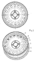
Figur 2 ein herkömmliches Fahrzeugrad, ebenfalls perspektivisch und in der Aufsicht. - Das in der
Figur 2 gezeigte, herkömmliche Fahrzeugrad weist ein Felgenband 1 und eine Radschüssel auf, die durch einen Kümpel 2, also eine Steifigkeitswelle, in eine innere Wandfläche 7, die sich zwischen dem Mittenloch 3 und dem Kümpel 2 erstreckt, und eine äußere Wandfläche 6, die zwischen Kümpel 2 und Felgenband 1 verläuft, unterteilt ist. - Im inneren Wandteil 7 ist ein das Mittenloch 3 umgebener Lochkreis 4 dargestellt, der zur Aufnahme der Stehbolzen dient, die das Rad oder genauer gesagt, die Radschüssel mit der Nabe (nicht dargestellt) verbinden.
- Im äußeren Wandteil 6, also zwischen Kümpel und Felgenband, sind konzentrisch angeordnete Belüftungslöcher 5 vorgesehen.
Ein derartiges Fahrzeugrad ist ausgelegt für die üblichen Lasten und Belastungen. - Vergleicht man diese Darstellung des herkömmlichen Fahrzeugrades mit der Darstellung des Fahrzeugrades in der
Figur 1 , so fällt gleich die wesentlich geringere Felgenbandbreite auf.
Durch die zusätzliche zweite Reihe der Belüftungslöcher 8, die sich in dem inneren Wandteil zwischen Lochkreis 4 und Kümpel 2 befinden, wird der Leichtbaugedanke verfolgt und Gewicht wird eingespart.
Dies wird deutlich, wenn man beispielsweise die Belüftungslochflächen * betrachtet und ein Verhältnis von innen/außen zwischen 0,5 und 0,6 ansetzt, so ergibt sich ein Verhältnis von etwa 0,72, wenn man das Schüsselgewicht ** ohne Belüftungslöcher bzw. mit Belüftungslöchern vergleicht.
Zum Vergleich: Bei einem Standardrad (vgl.Figur 2 ) liegt das Verhältnis bei etwa 0,9. - Weiterhin kann wesentlich mehr Energie (Abwärme) abtransportiert werden. Dies ist ein wichtiger Punkt für viele OEM's, um angrenzende Bauteile vor Überhitzung zu schützen.
- Durch die vorgeschlagene Bauweise ist es somit möglich, die konventionell hergestellte Radschüssel und Felge aus Stahl mit weniger Materialeinsatz zu produzieren.
- * (Belüftungslochfläche der Belüftungslöcher 8 - innen - ca. 29,6 mm2 Belüftungslochfläche der Belüftungslöcher 5 - außen - ca.52,2 mm2)
- ** (Schüsselgewicht ohne Belüftungslöcher 3,6 kg Schüsselgewicht mit Belüftungslöchern 2,6 kg)
Claims (7)
- Fahrzeugrad, aufweisend ein Felgenband (1) und eine Radschüssel (2,6,7), wobei die Radschüssel ein Mittenloch (3) zur Aufnahme einer Radnabe mit konzentrisch darum angeordnetem Lochkreis (4) zur Anordnung der Stehbolzen, sowie einen Kümpel (2) aufweist, der die Radschüssel in einen der Nabe zugekehrten inneren Wandteil (7) und einen dem Felgenband zugekehrten äußeren Wandteil (6) unterteilt, wobei im äußeren Wandteil (6) eine konzentrische Belüftungslochreihe (5) vorgesehen ist,
dadurch gekennzeichnet,
dass die Radschüssel (2,6,7) mit einem umlaufenden Flansch zur Anbindung an das Felgenband (1) ausgeführt ist und aus einem metallischen Werkstoff, insbesondere aus Stahl, besteht und dass in dem inneren Wandteil (7) der Radschüssel mindestens eine weitere konzentrische Belüftungslochreihe (8) ausgebildet ist. - Fahrzeugrad nach Anspruch 1,
dadurch gekennzeichnet,
dass die einzelnen Belüftungslöcher (5,8) im inneren Wandteil (7) bezogen auf den äußeren Wandteil (6) radial ausgerichtet sind. - Fahrzeugrad nach Anspruch 1,
dadurch gekennzeichnet,
dass die einzelnen Belüftungslöcher (5,8) im inneren Wandteil (7) bezogen auf den äußeren Wandteil (6) auf Lücke angeordnet sind. - Fahrzeugrad nach einem der vorstehenden Ansprüche,
dadurch gekennzeichnet,
dass die einzelnen Belüftungslöcher (5,8) im inneren Wandteil (7) bezogen auf den äußeren Wandteil (6) auf einer Linie oder in einem Winkel zueinander versetzt sind. - Fahrzeugrad nach einem der vorstehenden Ansprüche,
dadurch gekennzeichnet,
dass das Verhältnis der Belüftungslochfläche auf dem inneren Wandteil zu der auf dem äußeren Wandteil 0,5 bis 0,6 : 1 ist. - Fahrzeugrad nach den Ansprüchen 1-5,
dadurch gekennzeichnet,
dass die Belüftungslöcher (5,8) eine kreisrunde oder ovale Form aufweisen oder von Radmitte zu Radaußenseite konisch mit kontinuierlich veränderlichem und/oder diskontinuierlichem Querschnitt ausgeführt sind. - Fahrzeugrad nach den Ansprüchen 1-6,
dadurch gekennzeichnet,
dass die Radschüssel als TailoredWeldedBlank und/oder TailoredRolledBlank ausgeführt ist, wobei der innere Wandteil (7) andere Eigenschaften aufweist als der äußere Wandteil (6), insbesondere durch unterschiedliche Werkstoffe und/oder unterschiedliche Materialstärken.
Priority Applications (1)
| Application Number | Priority Date | Filing Date | Title |
|---|---|---|---|
| PL18167485T PL3424748T3 (pl) | 2017-06-22 | 2018-04-16 | Koło pojazdu |
Applications Claiming Priority (1)
| Application Number | Priority Date | Filing Date | Title |
|---|---|---|---|
| DE102017113826.9A DE102017113826A1 (de) | 2017-06-22 | 2017-06-22 | Fahrzeugrad |
Publications (2)
| Publication Number | Publication Date |
|---|---|
| EP3424748A1 true EP3424748A1 (de) | 2019-01-09 |
| EP3424748B1 EP3424748B1 (de) | 2021-06-09 |
Family
ID=62002078
Family Applications (1)
| Application Number | Title | Priority Date | Filing Date |
|---|---|---|---|
| EP18167485.4A Revoked EP3424748B1 (de) | 2017-06-22 | 2018-04-16 | Fahrzeugrad |
Country Status (5)
| Country | Link |
|---|---|
| EP (1) | EP3424748B1 (de) |
| CN (1) | CN109109557A (de) |
| DE (1) | DE102017113826A1 (de) |
| ES (1) | ES2886177T3 (de) |
| PL (1) | PL3424748T3 (de) |
Citations (4)
| Publication number | Priority date | Publication date | Assignee | Title |
|---|---|---|---|---|
| EP1162385A2 (de) * | 2000-06-08 | 2001-12-12 | Otto Sauer Achsenfabrik Keilberg | Radnabenflansch und Radnabe mit einem solchen |
| US20110241413A1 (en) * | 2010-03-30 | 2011-10-06 | Hiroyuki Uchida | Wheel for vehicle |
| DE102013101421A1 (de) * | 2013-02-13 | 2014-08-14 | Thyssenkrupp Steel Europe Ag | Rad mit Abdeckteilen |
| WO2016020890A1 (en) * | 2014-08-08 | 2016-02-11 | Gianetti Ruote S.R.L. | Wheel for industrial and commercial vehicles |
Family Cites Families (2)
| Publication number | Priority date | Publication date | Assignee | Title |
|---|---|---|---|---|
| DE10035187A1 (de) * | 2000-07-20 | 2002-02-07 | Thyssenkrupp Stahl Ag | Aus Stahlblech geformtes Fahrzeugrad |
| JP2015067011A (ja) * | 2013-09-27 | 2015-04-13 | トピー工業株式会社 | ホイールディスク及びそれを用いた車両用ホイール |
-
2017
- 2017-06-22 DE DE102017113826.9A patent/DE102017113826A1/de not_active Withdrawn
-
2018
- 2018-04-16 ES ES18167485T patent/ES2886177T3/es active Active
- 2018-04-16 EP EP18167485.4A patent/EP3424748B1/de not_active Revoked
- 2018-04-16 PL PL18167485T patent/PL3424748T3/pl unknown
- 2018-06-22 CN CN201810650299.3A patent/CN109109557A/zh active Pending
Patent Citations (4)
| Publication number | Priority date | Publication date | Assignee | Title |
|---|---|---|---|---|
| EP1162385A2 (de) * | 2000-06-08 | 2001-12-12 | Otto Sauer Achsenfabrik Keilberg | Radnabenflansch und Radnabe mit einem solchen |
| US20110241413A1 (en) * | 2010-03-30 | 2011-10-06 | Hiroyuki Uchida | Wheel for vehicle |
| DE102013101421A1 (de) * | 2013-02-13 | 2014-08-14 | Thyssenkrupp Steel Europe Ag | Rad mit Abdeckteilen |
| WO2016020890A1 (en) * | 2014-08-08 | 2016-02-11 | Gianetti Ruote S.R.L. | Wheel for industrial and commercial vehicles |
Also Published As
| Publication number | Publication date |
|---|---|
| ES2886177T3 (es) | 2021-12-16 |
| EP3424748B1 (de) | 2021-06-09 |
| PL3424748T3 (pl) | 2022-01-03 |
| CN109109557A (zh) | 2019-01-01 |
| DE102017113826A1 (de) | 2018-12-27 |
Similar Documents
| Publication | Publication Date | Title |
|---|---|---|
| DE102012022148B4 (de) | Zweiteiliger Radstern mit Profilspeichen | |
| EP3019340B1 (de) | Fahrzeugrad und verfahren zur herstellung eines fahrzeugrades | |
| DE102008048389B4 (de) | Felge für ein Kraftfahrzeug | |
| EP3416832B1 (de) | Fahrzeugrad und verwendung | |
| EP1951530B1 (de) | Fahrzeugrad und verfahren zu dessen herstellung | |
| DE102013101421A1 (de) | Rad mit Abdeckteilen | |
| DE102014112755B4 (de) | Verfahren zum Umformen eines Werkstücks, insbesondere einer Platine, aus Stahlblech | |
| DE10323833B4 (de) | Fahrzeugrad in Blechbauweise, insbesondere aus Stahlblech | |
| WO2019201635A1 (de) | Verfahren und werkzeug zur herstellung eines fahrzeug-rades | |
| EP1262333A2 (de) | Fahrzeugrad, insbesondere für Personenkraftwagen | |
| EP3218208B1 (de) | Elastisches rad für ein schienenfahrzeug | |
| DE202020100517U1 (de) | Felge für Fahrzeugrad und Fahrzeugrad hiermit | |
| EP0281903B1 (de) | Mehrteilige Felge | |
| DE102013222448B4 (de) | Rad, insbesondere für ein Kraftfahrzeug | |
| DE2207272A1 (de) | Fahrzeugrad | |
| EP3424748B1 (de) | Fahrzeugrad | |
| DE102014009074A1 (de) | Felge für ein Fahrzeugrad, insbesondere für ein Kraftfahrzeugrad | |
| EP3395744A1 (de) | Laufrad für einen kran | |
| WO2017137310A1 (de) | Nutzfahrzeugrad und verwendung | |
| EP1911604B1 (de) | Stahlrad und Verfahren zu dessen Herstellung | |
| EP3743228A1 (de) | Verfahren zur herstellung einer radschüssel | |
| EP2365190B1 (de) | Lagergehäusedeckel für eine Ladeeinrichtung | |
| DE102021000970B4 (de) | Federbeindomkonsole für einen Kraftwagen | |
| EP1174282A2 (de) | Aus Stahlblech geformtes Fahrzeugrad | |
| DE102013214451A1 (de) | Mehrschalige Statorplatte |
Legal Events
| Date | Code | Title | Description |
|---|---|---|---|
| PUAI | Public reference made under article 153(3) epc to a published international application that has entered the european phase |
Free format text: ORIGINAL CODE: 0009012 |
|
| STAA | Information on the status of an ep patent application or granted ep patent |
Free format text: STATUS: THE APPLICATION HAS BEEN PUBLISHED |
|
| AK | Designated contracting states |
Kind code of ref document: A1 Designated state(s): AL AT BE BG CH CY CZ DE DK EE ES FI FR GB GR HR HU IE IS IT LI LT LU LV MC MK MT NL NO PL PT RO RS SE SI SK SM TR |
|
| AX | Request for extension of the european patent |
Extension state: BA ME |
|
| STAA | Information on the status of an ep patent application or granted ep patent |
Free format text: STATUS: REQUEST FOR EXAMINATION WAS MADE |
|
| 17P | Request for examination filed |
Effective date: 20190221 |
|
| RBV | Designated contracting states (corrected) |
Designated state(s): AL AT BE BG CH CY CZ DE DK EE ES FI FR GB GR HR HU IE IS IT LI LT LU LV MC MK MT NL NO PL PT RO RS SE SI SK SM TR |
|
| RAP1 | Party data changed (applicant data changed or rights of an application transferred) |
Owner name: ACCURIDE WHEELS SOLINGEN GMBH |
|
| GRAP | Despatch of communication of intention to grant a patent |
Free format text: ORIGINAL CODE: EPIDOSNIGR1 |
|
| STAA | Information on the status of an ep patent application or granted ep patent |
Free format text: STATUS: GRANT OF PATENT IS INTENDED |
|
| INTG | Intention to grant announced |
Effective date: 20201202 |
|
| GRAS | Grant fee paid |
Free format text: ORIGINAL CODE: EPIDOSNIGR3 |
|
| GRAA | (expected) grant |
Free format text: ORIGINAL CODE: 0009210 |
|
| STAA | Information on the status of an ep patent application or granted ep patent |
Free format text: STATUS: THE PATENT HAS BEEN GRANTED |
|
| AK | Designated contracting states |
Kind code of ref document: B1 Designated state(s): AL AT BE BG CH CY CZ DE DK EE ES FI FR GB GR HR HU IE IS IT LI LT LU LV MC MK MT NL NO PL PT RO RS SE SI SK SM TR |
|
| REG | Reference to a national code |
Ref country code: GB Ref legal event code: FG4D Free format text: NOT ENGLISH |
|
| REG | Reference to a national code |
Ref country code: CH Ref legal event code: EP Ref country code: AT Ref legal event code: REF Ref document number: 1400152 Country of ref document: AT Kind code of ref document: T Effective date: 20210615 |
|
| REG | Reference to a national code |
Ref country code: DE Ref legal event code: R096 Ref document number: 502018005583 Country of ref document: DE |
|
| REG | Reference to a national code |
Ref country code: IE Ref legal event code: FG4D Free format text: LANGUAGE OF EP DOCUMENT: GERMAN |
|
| REG | Reference to a national code |
Ref country code: RO Ref legal event code: EPE |
|
| REG | Reference to a national code |
Ref country code: LT Ref legal event code: MG9D |
|
| PG25 | Lapsed in a contracting state [announced via postgrant information from national office to epo] |
Ref country code: LT Free format text: LAPSE BECAUSE OF FAILURE TO SUBMIT A TRANSLATION OF THE DESCRIPTION OR TO PAY THE FEE WITHIN THE PRESCRIBED TIME-LIMIT Effective date: 20210609 Ref country code: HR Free format text: LAPSE BECAUSE OF FAILURE TO SUBMIT A TRANSLATION OF THE DESCRIPTION OR TO PAY THE FEE WITHIN THE PRESCRIBED TIME-LIMIT Effective date: 20210609 Ref country code: FI Free format text: LAPSE BECAUSE OF FAILURE TO SUBMIT A TRANSLATION OF THE DESCRIPTION OR TO PAY THE FEE WITHIN THE PRESCRIBED TIME-LIMIT Effective date: 20210609 Ref country code: BG Free format text: LAPSE BECAUSE OF FAILURE TO SUBMIT A TRANSLATION OF THE DESCRIPTION OR TO PAY THE FEE WITHIN THE PRESCRIBED TIME-LIMIT Effective date: 20210909 |
|
| REG | Reference to a national code |
Ref country code: NL Ref legal event code: MP Effective date: 20210609 |
|
| PG25 | Lapsed in a contracting state [announced via postgrant information from national office to epo] |
Ref country code: GR Free format text: LAPSE BECAUSE OF FAILURE TO SUBMIT A TRANSLATION OF THE DESCRIPTION OR TO PAY THE FEE WITHIN THE PRESCRIBED TIME-LIMIT Effective date: 20210910 Ref country code: SE Free format text: LAPSE BECAUSE OF FAILURE TO SUBMIT A TRANSLATION OF THE DESCRIPTION OR TO PAY THE FEE WITHIN THE PRESCRIBED TIME-LIMIT Effective date: 20210609 Ref country code: RS Free format text: LAPSE BECAUSE OF FAILURE TO SUBMIT A TRANSLATION OF THE DESCRIPTION OR TO PAY THE FEE WITHIN THE PRESCRIBED TIME-LIMIT Effective date: 20210609 Ref country code: NO Free format text: LAPSE BECAUSE OF FAILURE TO SUBMIT A TRANSLATION OF THE DESCRIPTION OR TO PAY THE FEE WITHIN THE PRESCRIBED TIME-LIMIT Effective date: 20210909 Ref country code: LV Free format text: LAPSE BECAUSE OF FAILURE TO SUBMIT A TRANSLATION OF THE DESCRIPTION OR TO PAY THE FEE WITHIN THE PRESCRIBED TIME-LIMIT Effective date: 20210609 |
|
| REG | Reference to a national code |
Ref country code: ES Ref legal event code: FG2A Ref document number: 2886177 Country of ref document: ES Kind code of ref document: T3 Effective date: 20211216 |
|
| PG25 | Lapsed in a contracting state [announced via postgrant information from national office to epo] |
Ref country code: EE Free format text: LAPSE BECAUSE OF FAILURE TO SUBMIT A TRANSLATION OF THE DESCRIPTION OR TO PAY THE FEE WITHIN THE PRESCRIBED TIME-LIMIT Effective date: 20210609 Ref country code: SK Free format text: LAPSE BECAUSE OF FAILURE TO SUBMIT A TRANSLATION OF THE DESCRIPTION OR TO PAY THE FEE WITHIN THE PRESCRIBED TIME-LIMIT Effective date: 20210609 Ref country code: SM Free format text: LAPSE BECAUSE OF FAILURE TO SUBMIT A TRANSLATION OF THE DESCRIPTION OR TO PAY THE FEE WITHIN THE PRESCRIBED TIME-LIMIT Effective date: 20210609 Ref country code: NL Free format text: LAPSE BECAUSE OF FAILURE TO SUBMIT A TRANSLATION OF THE DESCRIPTION OR TO PAY THE FEE WITHIN THE PRESCRIBED TIME-LIMIT Effective date: 20210609 Ref country code: PT Free format text: LAPSE BECAUSE OF FAILURE TO SUBMIT A TRANSLATION OF THE DESCRIPTION OR TO PAY THE FEE WITHIN THE PRESCRIBED TIME-LIMIT Effective date: 20211011 |
|
| REG | Reference to a national code |
Ref country code: DE Ref legal event code: R026 Ref document number: 502018005583 Country of ref document: DE |
|
| PLBI | Opposition filed |
Free format text: ORIGINAL CODE: 0009260 |
|
| PLAX | Notice of opposition and request to file observation + time limit sent |
Free format text: ORIGINAL CODE: EPIDOSNOBS2 |
|
| 26 | Opposition filed |
Opponent name: MAXION WHEELS HOLDING GMBH Effective date: 20220309 |
|
| PG25 | Lapsed in a contracting state [announced via postgrant information from national office to epo] |
Ref country code: DK Free format text: LAPSE BECAUSE OF FAILURE TO SUBMIT A TRANSLATION OF THE DESCRIPTION OR TO PAY THE FEE WITHIN THE PRESCRIBED TIME-LIMIT Effective date: 20210609 |
|
| PG25 | Lapsed in a contracting state [announced via postgrant information from national office to epo] |
Ref country code: AL Free format text: LAPSE BECAUSE OF FAILURE TO SUBMIT A TRANSLATION OF THE DESCRIPTION OR TO PAY THE FEE WITHIN THE PRESCRIBED TIME-LIMIT Effective date: 20210609 |
|
| PLBB | Reply of patent proprietor to notice(s) of opposition received |
Free format text: ORIGINAL CODE: EPIDOSNOBS3 |
|
| PGFP | Annual fee paid to national office [announced via postgrant information from national office to epo] |
Ref country code: RO Payment date: 20220408 Year of fee payment: 5 Ref country code: IT Payment date: 20220420 Year of fee payment: 5 Ref country code: GB Payment date: 20220425 Year of fee payment: 5 Ref country code: FR Payment date: 20220421 Year of fee payment: 5 Ref country code: ES Payment date: 20220629 Year of fee payment: 5 Ref country code: DE Payment date: 20220420 Year of fee payment: 5 Ref country code: CZ Payment date: 20220414 Year of fee payment: 5 |
|
| RDAF | Communication despatched that patent is revoked |
Free format text: ORIGINAL CODE: EPIDOSNREV1 |
|
| REG | Reference to a national code |
Ref country code: DE Ref legal event code: R103 Ref document number: 502018005583 Country of ref document: DE Ref country code: DE Ref legal event code: R064 Ref document number: 502018005583 Country of ref document: DE |
|
| PGFP | Annual fee paid to national office [announced via postgrant information from national office to epo] |
Ref country code: PL Payment date: 20220407 Year of fee payment: 5 |
|
| RDAG | Patent revoked |
Free format text: ORIGINAL CODE: 0009271 |
|
| STAA | Information on the status of an ep patent application or granted ep patent |
Free format text: STATUS: PATENT REVOKED |
|
| REG | Reference to a national code |
Ref country code: CH Ref legal event code: PL |
|
| 27W | Patent revoked |
Effective date: 20220811 |
|
| GBPR | Gb: patent revoked under art. 102 of the ep convention designating the uk as contracting state |
Effective date: 20220811 |
|
| REG | Reference to a national code |
Ref country code: BE Ref legal event code: MM Effective date: 20220430 |
|
| PG25 | Lapsed in a contracting state [announced via postgrant information from national office to epo] |
Ref country code: MC Free format text: LAPSE BECAUSE OF FAILURE TO SUBMIT A TRANSLATION OF THE DESCRIPTION OR TO PAY THE FEE WITHIN THE PRESCRIBED TIME-LIMIT Effective date: 20210609 Ref country code: LU Free format text: LAPSE BECAUSE OF NON-PAYMENT OF DUE FEES Effective date: 20220416 |
|
| REG | Reference to a national code |
Ref country code: AT Ref legal event code: MA03 Ref document number: 1400152 Country of ref document: AT Kind code of ref document: T Effective date: 20220811 |
|
| PG25 | Lapsed in a contracting state [announced via postgrant information from national office to epo] |
Ref country code: BE Free format text: LAPSE BECAUSE OF NON-PAYMENT OF DUE FEES Effective date: 20220430 |
|
| PG25 | Lapsed in a contracting state [announced via postgrant information from national office to epo] |
Ref country code: MK Free format text: LAPSE BECAUSE OF FAILURE TO SUBMIT A TRANSLATION OF THE DESCRIPTION OR TO PAY THE FEE WITHIN THE PRESCRIBED TIME-LIMIT Effective date: 20210609 Ref country code: CY Free format text: LAPSE BECAUSE OF FAILURE TO SUBMIT A TRANSLATION OF THE DESCRIPTION OR TO PAY THE FEE WITHIN THE PRESCRIBED TIME-LIMIT Effective date: 20210609 |
|
| PG25 | Lapsed in a contracting state [announced via postgrant information from national office to epo] |
Ref country code: IE Free format text: LAPSE BECAUSE OF NON-PAYMENT OF DUE FEES Effective date: 20220416 |
|
| PG25 | Lapsed in a contracting state [announced via postgrant information from national office to epo] |
Ref country code: TR Free format text: LAPSE BECAUSE OF FAILURE TO SUBMIT A TRANSLATION OF THE DESCRIPTION OR TO PAY THE FEE WITHIN THE PRESCRIBED TIME-LIMIT Effective date: 20210609 Ref country code: IE Free format text: LAPSE BECAUSE OF NON-PAYMENT OF DUE FEES Effective date: 20220416 |
|
| PG25 | Lapsed in a contracting state [announced via postgrant information from national office to epo] |
Ref country code: HU Free format text: LAPSE BECAUSE OF FAILURE TO SUBMIT A TRANSLATION OF THE DESCRIPTION OR TO PAY THE FEE WITHIN THE PRESCRIBED TIME-LIMIT; INVALID AB INITIO Effective date: 20180416 |
|
| PGFP | Annual fee paid to national office [announced via postgrant information from national office to epo] |
Ref country code: AT Payment date: 20260410 Year of fee payment: 5 |