EP3424677A1 - Dispositif de commande pour installation de moulage par injection - Google Patents
Dispositif de commande pour installation de moulage par injection Download PDFInfo
- Publication number
- EP3424677A1 EP3424677A1 EP18176986.0A EP18176986A EP3424677A1 EP 3424677 A1 EP3424677 A1 EP 3424677A1 EP 18176986 A EP18176986 A EP 18176986A EP 3424677 A1 EP3424677 A1 EP 3424677A1
- Authority
- EP
- European Patent Office
- Prior art keywords
- control device
- injection
- jack
- workpiece
- arms
- Prior art date
- Legal status (The legal status is an assumption and is not a legal conclusion. Google has not performed a legal analysis and makes no representation as to the accuracy of the status listed.)
- Granted
Links
Images

Classifications
-
- B—PERFORMING OPERATIONS; TRANSPORTING
- B29—WORKING OF PLASTICS; WORKING OF SUBSTANCES IN A PLASTIC STATE IN GENERAL
- B29C—SHAPING OR JOINING OF PLASTICS; SHAPING OF MATERIAL IN A PLASTIC STATE, NOT OTHERWISE PROVIDED FOR; AFTER-TREATMENT OF THE SHAPED PRODUCTS, e.g. REPAIRING
- B29C45/00—Injection moulding, i.e. forcing the required volume of moulding material through a nozzle into a closed mould; Apparatus therefor
- B29C45/17—Component parts, details or accessories; Auxiliary operations
- B29C45/26—Moulds
- B29C45/27—Sprue channels ; Runner channels or runner nozzles
- B29C45/28—Closure devices therefor
- B29C45/2806—Closure devices therefor consisting of needle valve systems
- B29C45/281—Drive means therefor
-
- B—PERFORMING OPERATIONS; TRANSPORTING
- B29—WORKING OF PLASTICS; WORKING OF SUBSTANCES IN A PLASTIC STATE IN GENERAL
- B29C—SHAPING OR JOINING OF PLASTICS; SHAPING OF MATERIAL IN A PLASTIC STATE, NOT OTHERWISE PROVIDED FOR; AFTER-TREATMENT OF THE SHAPED PRODUCTS, e.g. REPAIRING
- B29C45/00—Injection moulding, i.e. forcing the required volume of moulding material through a nozzle into a closed mould; Apparatus therefor
- B29C45/17—Component parts, details or accessories; Auxiliary operations
- B29C45/26—Moulds
- B29C45/27—Sprue channels ; Runner channels or runner nozzles
- B29C45/28—Closure devices therefor
- B29C45/2806—Closure devices therefor consisting of needle valve systems
- B29C45/281—Drive means therefor
- B29C2045/2813—Common drive means for several needle valves
-
- B—PERFORMING OPERATIONS; TRANSPORTING
- B29—WORKING OF PLASTICS; WORKING OF SUBSTANCES IN A PLASTIC STATE IN GENERAL
- B29C—SHAPING OR JOINING OF PLASTICS; SHAPING OF MATERIAL IN A PLASTIC STATE, NOT OTHERWISE PROVIDED FOR; AFTER-TREATMENT OF THE SHAPED PRODUCTS, e.g. REPAIRING
- B29C45/00—Injection moulding, i.e. forcing the required volume of moulding material through a nozzle into a closed mould; Apparatus therefor
- B29C45/17—Component parts, details or accessories; Auxiliary operations
- B29C45/26—Moulds
- B29C45/27—Sprue channels ; Runner channels or runner nozzles
- B29C45/28—Closure devices therefor
- B29C45/2806—Closure devices therefor consisting of needle valve systems
- B29C45/281—Drive means therefor
- B29C2045/2827—Needle valves driven by an annular piston mounted around the nozzle
-
- B—PERFORMING OPERATIONS; TRANSPORTING
- B29—WORKING OF PLASTICS; WORKING OF SUBSTANCES IN A PLASTIC STATE IN GENERAL
- B29C—SHAPING OR JOINING OF PLASTICS; SHAPING OF MATERIAL IN A PLASTIC STATE, NOT OTHERWISE PROVIDED FOR; AFTER-TREATMENT OF THE SHAPED PRODUCTS, e.g. REPAIRING
- B29C45/00—Injection moulding, i.e. forcing the required volume of moulding material through a nozzle into a closed mould; Apparatus therefor
- B29C45/17—Component parts, details or accessories; Auxiliary operations
- B29C45/26—Moulds
- B29C45/27—Sprue channels ; Runner channels or runner nozzles
- B29C45/2735—Sprue channels ; Runner channels or runner nozzles for non-coaxial gates, e.g. for edge gates
Definitions
- the invention relates to a control device for an injection molding plant.
- the document US 5,855,934 discloses a control device for an injection molding plant comprising an axial nozzle for supplying fluid plastic of molding cavities, a workpiece to be moved axially, an annular actuator coaxial with the nozzle and mechanical means for connecting to the workpiece. move.
- the operation of the shutter is ensured by means of an annular piston which imposes an angular path to the supply channel of the fluid plastic material.
- the document EP 2 427 317 discloses injection tips for injection molding plant, equipped with injection threshold shutters. These shutters must be operated in synchronism to allow or stop the injection simultaneously to all the injection points of the installation. In the exemplary embodiment of a molding installation with four injection points aligned on one side of the fluid plastic distributor block, the shutters must be moved by a control device located behind the distribution block with respect to the spikes. injection. This results in two disadvantages: on the one hand an increase in the size of the molding installation, on the other hand a fragility of the shutters because of their great length.
- the object of the invention is to propose a control device for an injection molding installation which does not have the abovementioned disadvantages.
- the invention relates to a control device for an injection molding installation, comprising an axial hot nozzle for supplying fluid plastics molding cavities by means of a distributor block, and a workpiece to move axially during the molding operations, comprising an annular jack arranged coaxially with the hot nozzle, and mechanical means for connecting the jack to the workpiece, characterized in that the mechanical means for connecting the jack to the workpiece are constituted by arms carried by the jack and hooking rods carried by the part to be moved.
- the arms are four in number and regularly distributed on the upper face of the annular jack.
- the four arms have at their upper end a recessed profile for receiving a fastening rod.
- the attachment rods are two in number and fixed to the base of the part to be moved.
- the part to be moved is a battery of shutters able to close the injection thresholds of the molding cavities.
- an axial hot nozzle for the fluid plastic supply of molding cavities by means of a distributor block. It is also known to use molding cavities that are open and closed by linear movement movements.
- the invention applies to any part to move axially during injection molding operations, and the following description is made, by way of example, with reference to the particular embodiment of a battery of shutters.
- the battery 1 of shutters is composed of a base 2 and a body 3, substantially square shape.
- the body 3 carries on each of its four sides, four shutters 4, of identical length, each able to close an injection threshold.
- Such a battery 1 of shutters 4 is particularly adapted to the case of a lateral injection molding installation, comprising a parallelepipedal shaped distribution block, of substantially square section, providing, on each of its four lateral faces, the power supply. fluid plastic material of four injection points each terminating at an injection threshold.
- the distribution block (not shown) is fed by a hot nozzle 5 of vertical axis.
- the shutter control device is disposed under the distributor block, around the axial hot nozzle 5, so as not to increase the bulk of the injection molding installation. It consists essentially of an annular jack 6, substantially coaxial with the hot nozzle 5, and mechanical means of connection to the battery 1 of shutters 4. In the embodiment shown, these mechanical means are constituted by four arms 7 and two attachment rods 8. The four arms 7 are vertical, regularly distributed on the upper face 9 of the annular jack 6.
- the arms 7 have a hollow profile 10 adapted to receive a rod 8 attachment.
- Two hooking rods 8 are provided, arranged parallel to each other, each clinging to two arms 7.
- the rods 8 are fixed to the base 2 of the battery 1 of shutters.
- the base 2 being substantially square, the rods 8 are each fixed perpendicular to two opposite sides of the base and parallel to the other two sides.
- the arms 7 being hung by two on each rod 8, define in plan a square whose sides are parallel to those of the base 2 of the battery 1 shutters.
- the rotation positioning means of the annular jack 6 are essentially symbolized by two guide rods 11 sliding in ball rings 12 fixed in the carcass of the injection molding plant.
- the operation of the shutter control device proceeds in the following manner, the annular cylinder being initially in the low position, the shutters having released the injection thresholds.
- the injection of fluid plastic material into the molding cavities is performed.
- the control of the annular jack 6 upwards is triggered.
- the shutter battery is lifted by the cylinder 6 and the shutters reach the injection thresholds and seal them.
- the control of the annular cylinder 6 down is triggered and the shutter battery is lowered, releasing the injection thresholds for a new injection.
- the arrangement of the annular jack 6 coaxially with the hot nozzle 5 of the distribution block of the lateral injection molding plant is particularly advantageous because it gives a wide seat to the shutter battery while ensuring a relatively short stroke of shutters, which increases the operational safety.
Landscapes
- Engineering & Computer Science (AREA)
- Manufacturing & Machinery (AREA)
- Mechanical Engineering (AREA)
- Moulds For Moulding Plastics Or The Like (AREA)
- Injection Moulding Of Plastics Or The Like (AREA)
Abstract
Description
- L'invention concerne un dispositif de commande pour installation de moulage par injection.
- Le document
US 5 855 934 décrit un dispositif de commande pour installation de moulage par injection comprenant une buse axiale pour l'alimentation en matière plastique fluide de cavités moulantes, une pièce à déplacer axialement, un vérin annulaire coaxial à la buse et des moyens mécaniques de liaison à la pièce à déplacer. La manoeuvre de l'obturateur est assurée au moyen d'un piston annulaire qui impose un parcours anguleux au canal d'amenée de la matière plastique fluide. - Le document
EP 2 427 317 décrit des pointes d'injection pour installation de moulage par injection, équipées d'obturateurs de seuil d'injection. Ces obturateurs doivent être manoeuvrés en synchronisme pour autoriser ou arrêter l'injection simultanément à toutes les pointes d'injection de l'installation. Dans l'exemple de réalisation d'une installation de moulage à quatre pointes d'injection alignées sur une face du bloc répartiteur de matière plastique fluide, les obturateurs doivent être déplacés par un dispositif de commande situé en arrière du bloc répartiteur par rapport aux pointes d'injection. Il en résulte deux inconvénients : d'une part une augmentation de l'encombrement de l'installation de moulage, d'autre part une fragilité des obturateurs en raison de leur grande longueur. - L'invention a pour but de proposer un dispositif de commande pour installation de moulage par injection qui ne présente pas les inconvénients précités.
- L'invention a pour objet un dispositif de commande pour installation de moulage par injection, comportant une buse chaude axiale pour l'alimentation en matière plastique fluide de cavités moulantes au moyen d'un bloc répartiteur, et une pièce à déplacer axialement au cours des opérations de moulage, comprenant un vérin annulaire disposé coaxialement à la buse chaude, et des moyens mécaniques de liaison du vérin à la pièce à déplacer, caractérisé en ce que les moyens mécaniques de liaison du vérin à la pièce à déplacer sont constitués par des bras portés par le vérin et des tiges d'accrochage portées par la pièce à déplacer.
- Avantageusement, les bras sont au nombre de quatre et régulièrement répartis sur la face supérieure du vérin annulaire.
- De préférence, les quatre bras présentent à leur extrémité supérieure un profil en creux pour la réception d'une tige d'accrochage.
- Avantageusement, les tiges d'accrochage sont au nombre de deux et fixées à la base de la pièce à déplacer.
- Selon un mode de réalisation, la pièce à déplacer est une batterie d'obturateurs aptes à obturer les seuils d'injection des cavités moulantes.
- L'invention est décrite ci-après avec référence aux dessins annexés dans lesquels :
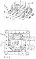
- La
Fig.1 est une vue simplifiée en perspective d'un exemple de réalisation d'une batterie d'obturateurs pour installation de moulage par injection à seize pointes d'injection. - La
Fig.2 est une vue simplifiée de dessus de la batterie d'obturateurs de laFig. 1 en position de fonctionnement. - La
Fig.3 est une vue simplifiée en perspective d'un exemple de réalisation du dispositif de commande selon l'invention en position de fonctionnement. - La
Fig.4 est une vue simplifiée en perspective du dispositif de commande selon laFig.3 montrant la liaison entre ledit dispositif et la batterie d'obturateurs. - La
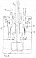
Fig. 5 est une vue simplifiée en coupe axiale de la partie centrale d'une installation de moulage par injection, réalisée dans le plan passant par les axes de deux bras opposés du dispositif de commande selon laFig.3 . - Dans une installation de moulage par injection, il est connu d'utiliser une buse chaude axiale pour l'alimentation en matière plastique fluide de cavités moulantes, au moyen d'un bloc répartiteur. Il est également connu d'utiliser des cavités moulantes qui sont ouvertes et fermées par des mouvements linéaires de déplacement. L'invention s'applique à toute pièce à déplacer axialement au cours des opérations de moulage par injection, et la description qui suit est faite, à titre d'exemple, avec référence au mode de réalisation particulier d'une batterie d'obturateurs.
- Dans l'exemple de réalisation de la
Fig.1 , la batterie 1 d'obturateurs est composée d'une base 2 et d'un corps 3, de forme sensiblement carrée. Le corps 3 porte sur chacun de ses quatre côtés, quatre obturateurs 4, de longueur identique, aptes chacun à obturer un seuil d'injection. Une telle batterie 1 d'obturateurs 4 est particulièrement adaptée au cas d'une installation de moulage par injection latérale, comportant un bloc répartiteur de forme parallélépipédique, de section sensiblement carrée, assurant, sur chacune de ses quatre faces latérales, l'alimentation en matière plastique fluide de quatre pointes d'injection aboutissant chacune à un seuil d'injection. - Le bloc répartiteur (non représenté) est alimenté par une buse chaude 5 d'axe vertical.
- Le dispositif de commande d'obturateurs selon l'invention est disposé sous le bloc répartiteur, autour de la buse chaude axiale 5, de façon à ne pas augmenter l'encombrement de l'installation de moulage par injection. Il est constitué essentiellement d'un vérin annulaire 6, sensiblement coaxial à la buse chaude 5, et de moyens mécaniques de liaison à la batterie 1 d'obturateurs 4. Dans l'exemple de réalisation représenté, ces moyens mécaniques sont constitués par quatre bras 7 et deux tiges d'accrochage 8. Les quatre bras 7 sont verticaux, régulièrement répartis sur la face supérieure 9 du vérin annulaire 6.
- A leur extrémité supérieure, les bras 7 présentent un profil en creux 10 apte à recevoir une tige 8 d'accrochage. Deux tiges 8 d'accrochage sont prévues, disposées parallèlement l'une à l'autre, chacune s'accrochant à deux bras 7. Les tiges 8 sont fixées à la base 2 de la batterie 1 d'obturateurs. La base 2 étant sensiblement carrée, les tiges 8 sont fixées chacune perpendiculairement à deux côtés opposés de la base et parallèlement aux deux autres côtés. Les bras 7 étant accrochés par deux sur chaque tige 8, définissent en plan un carré dont les côtés sont parallèles à ceux de la base 2 de la batterie 1 d'obturateurs.
- Dans l'exemple de réalisation représenté sur la
Fig. 5 , les moyens de positionnement en rotation du vérin annulaire 6 sont symbolisés essentiellement par deux tiges de guidage 11 coulissant dans des bagues à billes 12 fixées dans la carcasse de l'installation de moulage par injection. - Le fonctionnement du dispositif de commande d'obturateurs se déroule de la manière suivante, le vérin annulaire étant initialement en position basse, les obturateurs ayant libéré les seuils d'injection. L'injection de matière plastique fluide dans les cavités moulantes est effectuée. La commande du vérin annulaire 6 vers le haut est déclenchée. La batterie d'obturateurs est soulevée par le vérin 6 et les obturateurs atteignent les seuils d'injection et les obturent. Après libération des pièces moulées, la commande du vérin annulaire 6 vers le bas est déclenchée et la batterie d'obturateurs est descendue, libérant les seuils d'injection pour une nouvelle injection.
- La disposition du vérin annulaire 6 coaxialement à la buse chaude 5 d'alimentation du bloc répartiteur de l'installation de moulage par injection latérale est particulièrement avantageuse car elle donne une assise large à la batterie d'obturateurs tout en assurant une course relativement courte des obturateurs, ce qui augmente la sécurité de fonctionnement.
Claims (5)
- Dispositif de commande pour installation de moulage par injection, comportant une buse chaude axiale pour l'alimentation en matière plastique fluide de cavités moulantes au moyen d'un bloc répartiteur, et une pièce à déplacer axialement au cours des opération de moulage, comprenant un vérin annulaire (6) disposé coaxialement à la buse chaude (5) et des moyens mécaniques de liaison du vérin (6) à la pièce à déplacer, caractérisé en ce que les moyens mécaniques de liaison du vérin (6) à la pièce à déplacer sont constitués par des bras (7) portés par le vérin (6) et des tiges d'accrochage (8) portées par la pièce à déplacer.
- Dispositif de commande selon la revendication 1 caractérisé en ce que les bras (7) sont au nombre de quatre et régulièrement répartis sur la face supérieure (9) du vérin annulaire (6).
- Dispositif de commande selon la revendication 2 caractérisé en ce que les quatre bras (7) présentent à leur extrémité supérieure un profil en creux (10) pour la réception d'une tige (8) d'accrochage.
- Dispositif de commande selon la revendication 1 caractérisé en ce que les tiges (8) d'accrochage sont au nombre de deux et fixées à la base (2) de la pièce à déplacer.
- Dispositif de commande selon l'une des revendications 1 à 4 caractérisé en ce que la pièce à déplacer est une batterie (1) d'obturateurs aptes à obturer les seuils d'injection des cavités moulantes.
Applications Claiming Priority (1)
| Application Number | Priority Date | Filing Date | Title |
|---|---|---|---|
| FR1756363A FR3068638B1 (fr) | 2017-07-06 | 2017-07-06 | Dispositif de commande pour installation de moulage par injection |
Publications (2)
| Publication Number | Publication Date |
|---|---|
| EP3424677A1 true EP3424677A1 (fr) | 2019-01-09 |
| EP3424677B1 EP3424677B1 (fr) | 2020-03-11 |
Family
ID=60020038
Family Applications (1)
| Application Number | Title | Priority Date | Filing Date |
|---|---|---|---|
| EP18176986.0A Active EP3424677B1 (fr) | 2017-07-06 | 2018-06-11 | Dispositif de commande pour installation de moulage par injection |
Country Status (3)
| Country | Link |
|---|---|
| EP (1) | EP3424677B1 (fr) |
| ES (1) | ES2787474T3 (fr) |
| FR (1) | FR3068638B1 (fr) |
Citations (4)
| Publication number | Priority date | Publication date | Assignee | Title |
|---|---|---|---|---|
| US5855934A (en) | 1997-05-27 | 1999-01-05 | Tradesco Mold Limited | Valve pin actuator |
| DE10321355A1 (de) * | 2002-10-15 | 2004-05-06 | Klöckner Desma Elastomertechnik GmbH | Düse |
| EP2427317A2 (fr) | 2009-05-06 | 2012-03-14 | EWIKON Heisskanalsysteme GmbH | Buse à canal chaud pour l'injection latérale sur des objets |
| CN205889750U (zh) * | 2016-06-16 | 2017-01-18 | 喻铁军 | 一种伺服阀针热流道系统 |
Family Cites Families (1)
| Publication number | Priority date | Publication date | Assignee | Title |
|---|---|---|---|---|
| DE19920331B4 (de) * | 1999-05-03 | 2006-04-20 | Yudo Co., Ltd. | Einspritzdüse für Spritzgießmaschinen |
-
2017
- 2017-07-06 FR FR1756363A patent/FR3068638B1/fr not_active Expired - Fee Related
-
2018
- 2018-06-11 ES ES18176986T patent/ES2787474T3/es active Active
- 2018-06-11 EP EP18176986.0A patent/EP3424677B1/fr active Active
Patent Citations (4)
| Publication number | Priority date | Publication date | Assignee | Title |
|---|---|---|---|---|
| US5855934A (en) | 1997-05-27 | 1999-01-05 | Tradesco Mold Limited | Valve pin actuator |
| DE10321355A1 (de) * | 2002-10-15 | 2004-05-06 | Klöckner Desma Elastomertechnik GmbH | Düse |
| EP2427317A2 (fr) | 2009-05-06 | 2012-03-14 | EWIKON Heisskanalsysteme GmbH | Buse à canal chaud pour l'injection latérale sur des objets |
| CN205889750U (zh) * | 2016-06-16 | 2017-01-18 | 喻铁军 | 一种伺服阀针热流道系统 |
Also Published As
| Publication number | Publication date |
|---|---|
| EP3424677B1 (fr) | 2020-03-11 |
| ES2787474T3 (es) | 2020-10-16 |
| FR3068638B1 (fr) | 2020-05-15 |
| FR3068638A1 (fr) | 2019-01-11 |
Similar Documents
| Publication | Publication Date | Title |
|---|---|---|
| EP2714511B1 (fr) | Dispositif d'ouverture d'urgence d'une porte d'aeronef | |
| WO2018215705A1 (fr) | Prehenseur pour manipulateur, muni de bras de prehension comprenant des branches reliees par des organes d'articulation a changement d'etats | |
| FR2972385A1 (fr) | Systeme automatise pour le changement de moule d'une unite de moulage equipant une machine de fabrication de recipients | |
| FR3028836A1 (fr) | Actionneur de gouverne de commande de vol d'un aeronef | |
| FR2958979A1 (fr) | Systeme de commande de type hydraulique pour dispositif d'inversion de poussee | |
| EP3026310B1 (fr) | Vanne électromagnétique pour gaz haute pression cryogénique | |
| FR2934191A1 (fr) | Perfectionnement a un dispositif pour l'insertion et l'extraction d'axes d'articulation de maillons de chaines | |
| CA2744923C (fr) | Systeme d'injection de matiere thermoplastique | |
| EP3424677B1 (fr) | Dispositif de commande pour installation de moulage par injection | |
| FR3032376A1 (fr) | Ensemble de moulage et procede de fabrication d'un corps de seringue. | |
| FR2679480A1 (fr) | Pince pneumatique. | |
| FR2502227A1 (fr) | Dispositif de commande hydraulique d'une porte de capot en particulier pour moteur d'avion avec dispositif de charge antivibration, et ensemble utilisant ces dispositifs | |
| FR2780908A1 (fr) | Dispositif de positionnement et de centrage | |
| EP2011582B1 (fr) | Installation de chargement séquentiel de barres de matériau dans une machine d'usinage | |
| FR3100732A1 (fr) | Dispositif et procédé de clampage d'un effecteur sur une peau. | |
| FR2658587A1 (fr) | Installation pour la manutention de chapeaux de bouteilles a gaz, avant et apres le remplissage de ces bouteilles. | |
| EP3578460A1 (fr) | Atterrisseur d'aeronef muni de moyens de routage de cables et tuyaux | |
| EP2836336A1 (fr) | Dispositif de serrage d'une pièce sur un outillage | |
| FR3098430A1 (fr) | Système de préhension par couplage magnétique | |
| EP2892806B1 (fr) | Boitier a accessoires pour la commande de volets d'un aéronef | |
| FR2913175A1 (fr) | Dispositif de jonction entre un vehicule et un bras articule lateral porteur d'une tete de travail. | |
| FR3089143A1 (fr) | Dispositif de préhension à têtes magnétiques orientables | |
| EP2872784B1 (fr) | Dispositif de commande du déplacement d'un vérin hydraulique, notamment pour machines hydrauliques | |
| FR3128653A1 (fr) | Système de préhension | |
| FR2762887A1 (fr) | Outillage de demontage de l'opercule d'une vanne papillon, procede de demontage mettant en oeuvre un tel outillage et vanne papillon adaptee a la mise en oeuvre dudit procede de demontage |
Legal Events
| Date | Code | Title | Description |
|---|---|---|---|
| PUAI | Public reference made under article 153(3) epc to a published international application that has entered the european phase |
Free format text: ORIGINAL CODE: 0009012 |
|
| STAA | Information on the status of an ep patent application or granted ep patent |
Free format text: STATUS: THE APPLICATION HAS BEEN PUBLISHED |
|
| AK | Designated contracting states |
Kind code of ref document: A1 Designated state(s): AL AT BE BG CH CY CZ DE DK EE ES FI FR GB GR HR HU IE IS IT LI LT LU LV MC MK MT NL NO PL PT RO RS SE SI SK SM TR |
|
| AX | Request for extension of the european patent |
Extension state: BA ME |
|
| STAA | Information on the status of an ep patent application or granted ep patent |
Free format text: STATUS: REQUEST FOR EXAMINATION WAS MADE |
|
| 17P | Request for examination filed |
Effective date: 20190624 |
|
| RBV | Designated contracting states (corrected) |
Designated state(s): AL AT BE BG CH CY CZ DE DK EE ES FI FR GB GR HR HU IE IS IT LI LT LU LV MC MK MT NL NO PL PT RO RS SE SI SK SM TR |
|
| GRAP | Despatch of communication of intention to grant a patent |
Free format text: ORIGINAL CODE: EPIDOSNIGR1 |
|
| STAA | Information on the status of an ep patent application or granted ep patent |
Free format text: STATUS: GRANT OF PATENT IS INTENDED |
|
| INTG | Intention to grant announced |
Effective date: 20200110 |
|
| GRAS | Grant fee paid |
Free format text: ORIGINAL CODE: EPIDOSNIGR3 |
|
| GRAA | (expected) grant |
Free format text: ORIGINAL CODE: 0009210 |
|
| STAA | Information on the status of an ep patent application or granted ep patent |
Free format text: STATUS: THE PATENT HAS BEEN GRANTED |
|
| AK | Designated contracting states |
Kind code of ref document: B1 Designated state(s): AL AT BE BG CH CY CZ DE DK EE ES FI FR GB GR HR HU IE IS IT LI LT LU LV MC MK MT NL NO PL PT RO RS SE SI SK SM TR |
|
| REG | Reference to a national code |
Ref country code: GB Ref legal event code: FG4D Free format text: NOT ENGLISH |
|
| REG | Reference to a national code |
Ref country code: CH Ref legal event code: EP |
|
| REG | Reference to a national code |
Ref country code: AT Ref legal event code: REF Ref document number: 1242575 Country of ref document: AT Kind code of ref document: T Effective date: 20200315 |
|
| REG | Reference to a national code |
Ref country code: IE Ref legal event code: FG4D Free format text: LANGUAGE OF EP DOCUMENT: FRENCH |
|
| REG | Reference to a national code |
Ref country code: DE Ref legal event code: R096 Ref document number: 602018002951 Country of ref document: DE |
|
| PG25 | Lapsed in a contracting state [announced via postgrant information from national office to epo] |
Ref country code: FI Free format text: LAPSE BECAUSE OF FAILURE TO SUBMIT A TRANSLATION OF THE DESCRIPTION OR TO PAY THE FEE WITHIN THE PRESCRIBED TIME-LIMIT Effective date: 20200311 Ref country code: NO Free format text: LAPSE BECAUSE OF FAILURE TO SUBMIT A TRANSLATION OF THE DESCRIPTION OR TO PAY THE FEE WITHIN THE PRESCRIBED TIME-LIMIT Effective date: 20200611 Ref country code: RS Free format text: LAPSE BECAUSE OF FAILURE TO SUBMIT A TRANSLATION OF THE DESCRIPTION OR TO PAY THE FEE WITHIN THE PRESCRIBED TIME-LIMIT Effective date: 20200311 |
|
| REG | Reference to a national code |
Ref country code: NL Ref legal event code: MP Effective date: 20200311 |
|
| PG25 | Lapsed in a contracting state [announced via postgrant information from national office to epo] |
Ref country code: BG Free format text: LAPSE BECAUSE OF FAILURE TO SUBMIT A TRANSLATION OF THE DESCRIPTION OR TO PAY THE FEE WITHIN THE PRESCRIBED TIME-LIMIT Effective date: 20200611 Ref country code: LV Free format text: LAPSE BECAUSE OF FAILURE TO SUBMIT A TRANSLATION OF THE DESCRIPTION OR TO PAY THE FEE WITHIN THE PRESCRIBED TIME-LIMIT Effective date: 20200311 Ref country code: SE Free format text: LAPSE BECAUSE OF FAILURE TO SUBMIT A TRANSLATION OF THE DESCRIPTION OR TO PAY THE FEE WITHIN THE PRESCRIBED TIME-LIMIT Effective date: 20200311 Ref country code: HR Free format text: LAPSE BECAUSE OF FAILURE TO SUBMIT A TRANSLATION OF THE DESCRIPTION OR TO PAY THE FEE WITHIN THE PRESCRIBED TIME-LIMIT Effective date: 20200311 Ref country code: GR Free format text: LAPSE BECAUSE OF FAILURE TO SUBMIT A TRANSLATION OF THE DESCRIPTION OR TO PAY THE FEE WITHIN THE PRESCRIBED TIME-LIMIT Effective date: 20200612 |
|
| REG | Reference to a national code |
Ref country code: LT Ref legal event code: MG4D |
|
| PG25 | Lapsed in a contracting state [announced via postgrant information from national office to epo] |
Ref country code: NL Free format text: LAPSE BECAUSE OF FAILURE TO SUBMIT A TRANSLATION OF THE DESCRIPTION OR TO PAY THE FEE WITHIN THE PRESCRIBED TIME-LIMIT Effective date: 20200311 |
|
| REG | Reference to a national code |
Ref country code: ES Ref legal event code: FG2A Ref document number: 2787474 Country of ref document: ES Kind code of ref document: T3 Effective date: 20201016 |
|
| PG25 | Lapsed in a contracting state [announced via postgrant information from national office to epo] |
Ref country code: PT Free format text: LAPSE BECAUSE OF FAILURE TO SUBMIT A TRANSLATION OF THE DESCRIPTION OR TO PAY THE FEE WITHIN THE PRESCRIBED TIME-LIMIT Effective date: 20200805 Ref country code: SK Free format text: LAPSE BECAUSE OF FAILURE TO SUBMIT A TRANSLATION OF THE DESCRIPTION OR TO PAY THE FEE WITHIN THE PRESCRIBED TIME-LIMIT Effective date: 20200311 Ref country code: IS Free format text: LAPSE BECAUSE OF FAILURE TO SUBMIT A TRANSLATION OF THE DESCRIPTION OR TO PAY THE FEE WITHIN THE PRESCRIBED TIME-LIMIT Effective date: 20200711 Ref country code: SM Free format text: LAPSE BECAUSE OF FAILURE TO SUBMIT A TRANSLATION OF THE DESCRIPTION OR TO PAY THE FEE WITHIN THE PRESCRIBED TIME-LIMIT Effective date: 20200311 Ref country code: EE Free format text: LAPSE BECAUSE OF FAILURE TO SUBMIT A TRANSLATION OF THE DESCRIPTION OR TO PAY THE FEE WITHIN THE PRESCRIBED TIME-LIMIT Effective date: 20200311 Ref country code: RO Free format text: LAPSE BECAUSE OF FAILURE TO SUBMIT A TRANSLATION OF THE DESCRIPTION OR TO PAY THE FEE WITHIN THE PRESCRIBED TIME-LIMIT Effective date: 20200311 Ref country code: CZ Free format text: LAPSE BECAUSE OF FAILURE TO SUBMIT A TRANSLATION OF THE DESCRIPTION OR TO PAY THE FEE WITHIN THE PRESCRIBED TIME-LIMIT Effective date: 20200311 Ref country code: LT Free format text: LAPSE BECAUSE OF FAILURE TO SUBMIT A TRANSLATION OF THE DESCRIPTION OR TO PAY THE FEE WITHIN THE PRESCRIBED TIME-LIMIT Effective date: 20200311 |
|
| REG | Reference to a national code |
Ref country code: AT Ref legal event code: MK05 Ref document number: 1242575 Country of ref document: AT Kind code of ref document: T Effective date: 20200311 |
|
| REG | Reference to a national code |
Ref country code: DE Ref legal event code: R097 Ref document number: 602018002951 Country of ref document: DE |
|
| PLBE | No opposition filed within time limit |
Free format text: ORIGINAL CODE: 0009261 |
|
| STAA | Information on the status of an ep patent application or granted ep patent |
Free format text: STATUS: NO OPPOSITION FILED WITHIN TIME LIMIT |
|
| PG25 | Lapsed in a contracting state [announced via postgrant information from national office to epo] |
Ref country code: IT Free format text: LAPSE BECAUSE OF FAILURE TO SUBMIT A TRANSLATION OF THE DESCRIPTION OR TO PAY THE FEE WITHIN THE PRESCRIBED TIME-LIMIT Effective date: 20200311 Ref country code: AT Free format text: LAPSE BECAUSE OF FAILURE TO SUBMIT A TRANSLATION OF THE DESCRIPTION OR TO PAY THE FEE WITHIN THE PRESCRIBED TIME-LIMIT Effective date: 20200311 Ref country code: DK Free format text: LAPSE BECAUSE OF FAILURE TO SUBMIT A TRANSLATION OF THE DESCRIPTION OR TO PAY THE FEE WITHIN THE PRESCRIBED TIME-LIMIT Effective date: 20200311 Ref country code: MC Free format text: LAPSE BECAUSE OF FAILURE TO SUBMIT A TRANSLATION OF THE DESCRIPTION OR TO PAY THE FEE WITHIN THE PRESCRIBED TIME-LIMIT Effective date: 20200311 |
|
| 26N | No opposition filed |
Effective date: 20201214 |
|
| PG25 | Lapsed in a contracting state [announced via postgrant information from national office to epo] |
Ref country code: PL Free format text: LAPSE BECAUSE OF FAILURE TO SUBMIT A TRANSLATION OF THE DESCRIPTION OR TO PAY THE FEE WITHIN THE PRESCRIBED TIME-LIMIT Effective date: 20200311 Ref country code: SI Free format text: LAPSE BECAUSE OF FAILURE TO SUBMIT A TRANSLATION OF THE DESCRIPTION OR TO PAY THE FEE WITHIN THE PRESCRIBED TIME-LIMIT Effective date: 20200311 |
|
| PG25 | Lapsed in a contracting state [announced via postgrant information from national office to epo] |
Ref country code: LU Free format text: LAPSE BECAUSE OF NON-PAYMENT OF DUE FEES Effective date: 20200611 |
|
| REG | Reference to a national code |
Ref country code: BE Ref legal event code: MM Effective date: 20200630 |
|
| PG25 | Lapsed in a contracting state [announced via postgrant information from national office to epo] |
Ref country code: IE Free format text: LAPSE BECAUSE OF NON-PAYMENT OF DUE FEES Effective date: 20200611 |
|
| PG25 | Lapsed in a contracting state [announced via postgrant information from national office to epo] |
Ref country code: BE Free format text: LAPSE BECAUSE OF NON-PAYMENT OF DUE FEES Effective date: 20200630 |
|
| PG25 | Lapsed in a contracting state [announced via postgrant information from national office to epo] |
Ref country code: TR Free format text: LAPSE BECAUSE OF FAILURE TO SUBMIT A TRANSLATION OF THE DESCRIPTION OR TO PAY THE FEE WITHIN THE PRESCRIBED TIME-LIMIT Effective date: 20200311 Ref country code: MT Free format text: LAPSE BECAUSE OF FAILURE TO SUBMIT A TRANSLATION OF THE DESCRIPTION OR TO PAY THE FEE WITHIN THE PRESCRIBED TIME-LIMIT Effective date: 20200311 Ref country code: CY Free format text: LAPSE BECAUSE OF FAILURE TO SUBMIT A TRANSLATION OF THE DESCRIPTION OR TO PAY THE FEE WITHIN THE PRESCRIBED TIME-LIMIT Effective date: 20200311 |
|
| PG25 | Lapsed in a contracting state [announced via postgrant information from national office to epo] |
Ref country code: MK Free format text: LAPSE BECAUSE OF FAILURE TO SUBMIT A TRANSLATION OF THE DESCRIPTION OR TO PAY THE FEE WITHIN THE PRESCRIBED TIME-LIMIT Effective date: 20200311 Ref country code: AL Free format text: LAPSE BECAUSE OF FAILURE TO SUBMIT A TRANSLATION OF THE DESCRIPTION OR TO PAY THE FEE WITHIN THE PRESCRIBED TIME-LIMIT Effective date: 20200311 |
|
| GBPC | Gb: european patent ceased through non-payment of renewal fee |
Effective date: 20220611 |
|
| PG25 | Lapsed in a contracting state [announced via postgrant information from national office to epo] |
Ref country code: GB Free format text: LAPSE BECAUSE OF NON-PAYMENT OF DUE FEES Effective date: 20220611 |
|
| PGFP | Annual fee paid to national office [announced via postgrant information from national office to epo] |
Ref country code: ES Payment date: 20250728 Year of fee payment: 8 |
|
| PGFP | Annual fee paid to national office [announced via postgrant information from national office to epo] |
Ref country code: CH Payment date: 20250707 Year of fee payment: 8 |
|
| REG | Reference to a national code |
Ref country code: CH Ref legal event code: U11 Free format text: ST27 STATUS EVENT CODE: U-0-0-U10-U11 (AS PROVIDED BY THE NATIONAL OFFICE) Effective date: 20260701 |
|
| PGFP | Annual fee paid to national office [announced via postgrant information from national office to epo] |
Ref country code: DE Payment date: 20260622 Year of fee payment: 9 |
|
| PGFP | Annual fee paid to national office [announced via postgrant information from national office to epo] |
Ref country code: FR Payment date: 20260626 Year of fee payment: 9 |