EP3424435A1 - Ultrasonic endoscope - Google Patents
Ultrasonic endoscope Download PDFInfo
- Publication number
- EP3424435A1 EP3424435A1 EP16892652.5A EP16892652A EP3424435A1 EP 3424435 A1 EP3424435 A1 EP 3424435A1 EP 16892652 A EP16892652 A EP 16892652A EP 3424435 A1 EP3424435 A1 EP 3424435A1
- Authority
- EP
- European Patent Office
- Prior art keywords
- distance
- balloon
- ultrasound
- distal end
- wall portion
- Prior art date
- Legal status (The legal status is an assumption and is not a legal conclusion. Google has not performed a legal analysis and makes no representation as to the accuracy of the status listed.)
- Withdrawn
Links
Images




Classifications
-
- A—HUMAN NECESSITIES
- A61—MEDICAL OR VETERINARY SCIENCE; HYGIENE
- A61B—DIAGNOSIS; SURGERY; IDENTIFICATION
- A61B8/00—Diagnosis using ultrasonic, sonic or infrasonic waves
- A61B8/44—Constructional features of the ultrasonic, sonic or infrasonic diagnostic device
- A61B8/4444—Constructional features of the ultrasonic, sonic or infrasonic diagnostic device related to the probe
- A61B8/4461—Features of the scanning mechanism, e.g. for moving the transducer within the housing of the probe
-
- A—HUMAN NECESSITIES
- A61—MEDICAL OR VETERINARY SCIENCE; HYGIENE
- A61B—DIAGNOSIS; SURGERY; IDENTIFICATION
- A61B1/00—Instruments for performing medical examinations of the interior of cavities or tubes of the body by visual or photographical inspection, e.g. endoscopes; Illuminating arrangements therefor
- A61B1/00064—Constructional details of the endoscope body
- A61B1/00071—Insertion part of the endoscope body
- A61B1/0008—Insertion part of the endoscope body characterised by distal tip features
- A61B1/00082—Balloons
-
- A—HUMAN NECESSITIES
- A61—MEDICAL OR VETERINARY SCIENCE; HYGIENE
- A61B—DIAGNOSIS; SURGERY; IDENTIFICATION
- A61B1/00—Instruments for performing medical examinations of the interior of cavities or tubes of the body by visual or photographical inspection, e.g. endoscopes; Illuminating arrangements therefor
- A61B1/00064—Constructional details of the endoscope body
- A61B1/00071—Insertion part of the endoscope body
- A61B1/0008—Insertion part of the endoscope body characterised by distal tip features
- A61B1/00101—Insertion part of the endoscope body characterised by distal tip features the distal tip features being detachable
-
- A—HUMAN NECESSITIES
- A61—MEDICAL OR VETERINARY SCIENCE; HYGIENE
- A61B—DIAGNOSIS; SURGERY; IDENTIFICATION
- A61B8/00—Diagnosis using ultrasonic, sonic or infrasonic waves
- A61B8/12—Diagnosis using ultrasonic, sonic or infrasonic waves in body cavities or body tracts, e.g. by using catheters
-
- A—HUMAN NECESSITIES
- A61—MEDICAL OR VETERINARY SCIENCE; HYGIENE
- A61B—DIAGNOSIS; SURGERY; IDENTIFICATION
- A61B8/00—Diagnosis using ultrasonic, sonic or infrasonic waves
- A61B8/44—Constructional features of the ultrasonic, sonic or infrasonic diagnostic device
- A61B8/4444—Constructional features of the ultrasonic, sonic or infrasonic diagnostic device related to the probe
- A61B8/445—Details of catheter construction
-
- A—HUMAN NECESSITIES
- A61—MEDICAL OR VETERINARY SCIENCE; HYGIENE
- A61B—DIAGNOSIS; SURGERY; IDENTIFICATION
- A61B8/00—Diagnosis using ultrasonic, sonic or infrasonic waves
- A61B8/44—Constructional features of the ultrasonic, sonic or infrasonic diagnostic device
- A61B8/4444—Constructional features of the ultrasonic, sonic or infrasonic diagnostic device related to the probe
- A61B8/4455—Features of the external shape of the probe, e.g. ergonomic aspects
-
- A—HUMAN NECESSITIES
- A61—MEDICAL OR VETERINARY SCIENCE; HYGIENE
- A61B—DIAGNOSIS; SURGERY; IDENTIFICATION
- A61B1/00—Instruments for performing medical examinations of the interior of cavities or tubes of the body by visual or photographical inspection, e.g. endoscopes; Illuminating arrangements therefor
- A61B1/06—Instruments for performing medical examinations of the interior of cavities or tubes of the body by visual or photographical inspection, e.g. endoscopes; Illuminating arrangements therefor with illuminating arrangements
- A61B1/0661—Endoscope light sources
-
- A—HUMAN NECESSITIES
- A61—MEDICAL OR VETERINARY SCIENCE; HYGIENE
- A61B—DIAGNOSIS; SURGERY; IDENTIFICATION
- A61B8/00—Diagnosis using ultrasonic, sonic or infrasonic waves
- A61B8/42—Details of probe positioning or probe attachment to the patient
- A61B8/4272—Details of probe positioning or probe attachment to the patient involving the acoustic interface between the transducer and the tissue
- A61B8/4281—Details of probe positioning or probe attachment to the patient involving the acoustic interface between the transducer and the tissue characterised by sound-transmitting media or devices for coupling the transducer to the tissue
-
- A—HUMAN NECESSITIES
- A61—MEDICAL OR VETERINARY SCIENCE; HYGIENE
- A61B—DIAGNOSIS; SURGERY; IDENTIFICATION
- A61B8/00—Diagnosis using ultrasonic, sonic or infrasonic waves
- A61B8/44—Constructional features of the ultrasonic, sonic or infrasonic diagnostic device
- A61B8/4483—Constructional features of the ultrasonic, sonic or infrasonic diagnostic device characterised by features of the ultrasound transducer
- A61B8/4488—Constructional features of the ultrasonic, sonic or infrasonic diagnostic device characterised by features of the ultrasound transducer the transducer being a phased array
Definitions
- the present invention relates to an ultrasound endoscope.
- the balloon With the ultrasound endoscope that performs observation by using such a balloon, the balloon needs to be removed from the ultrasound endoscope after the observation.
- Patent Literature 1 Japanese Laid-open Patent Publication No. 2006-204642
- the present invention has been conceived in light of the circumstances described above, and an object thereof is to provide an ultrasound endoscope in which a balloon is easily removed.
- an ultrasound endoscope includes: an ultrasound transducer that is provided at a distal end of an insertion portion configured to be inserted into a subject, the ultrasound transducer being configured to send ultrasound into the subject and receive the ultrasound reflected in the subject; a balloon groove that is provided on at least one side of a distal end side and a proximal end side of the ultrasound transducer and in which a balloon band is fitted, the balloon band being provided at an end portion of a balloon that is attached to cover an outer surface of the ultrasound transducer; a contact portion that constitutes a bottom surface of the balloon groove and that is in contact with the balloon band; a first wall portion that includes a first wall surface being a surface constituting the balloon groove on a ultrasound transducer side and in which a first distance that is a distance from a center of a cross section orthogonal to an extension direction of the insertion portion to an outer circumference of the first wall surface is larger than a second distance
- the first distance of a portion of the first wall portion across the balloon groove from the notch portion is larger than a distance from the center of the cross section to an outer circumference of the surface that is formed on the notch portion.
- the notch portion is formed on the second wall portion of a distal end side of the balloon groove provided on the distal end side of the ultrasound transducer.
- the ultrasound endoscope further includes an acoustic lens configured to cover an outer circumference of the ultrasound transducer.
- an acoustic lens configured to cover an outer circumference of the ultrasound transducer.
- an inclined surface in which the first distance is decreased toward a distal end side along the extension direction of the insertion portion is formed on the first wall portion facing the notch portion in the cross section of the first wall portion.
- the inclined surface is formed on the entire circumference of the first wall portion.
- the balloon band that is fitted into the balloon groove can be visually recognized.
- an ultrasound endoscope in which a balloon is easily removed.
- an ultrasound endoscope according to the present invention will be explained with reference to accompanying drawings. Furthermore, the present invention is not limited to the embodiments.
- an ultrasound endoscope in which a balloon groove is formed on both the proximal end side and the distal end side of an ultrasound transducer is described as an example; however, the ultrasound endoscope according to the present invention can be applied to a typically used ultrasound endoscope in which a balloon groove is formed and also applied to an ultrasound endoscope in which, for example, a balloon groove is formed only on the proximal end side of an ultrasound transducer.
- FIG. 1 is a schematic view illustrating an ultrasound endoscope system that includes an ultrasound endoscope according to an embodiment of the present invention.
- An ultrasound endoscope system 1 illustrated in FIG. 1 includes an ultrasound endoscope 2, an endoscope observation apparatus 3, an ultrasound observation apparatus 4, a display device 5, a light source device 6, a video cable 7 that connects the ultrasound endoscope 2 and the endoscope observation apparatus 3, an ultrasound cable 8 that connects the ultrasound endoscope 2 and the ultrasound observation apparatus 4, and a light source cable 9 that connects the ultrasound endoscope 2 and the light source device 6.
- the ultrasound endoscope 2 is formed by combining an endoscope observation unit, which has observation optical system constituted by lenses or the like and has an image sensor, and an ultrasound transducer and has an endoscope observation function and an ultrasound measurement function.
- the endoscope observation apparatus 3 controls the endoscope observation function and processes an output signal that is output from the ultrasound endoscope 2 obtained from endoscope observation.
- the ultrasound observation apparatus 4 controls the ultrasound measurement function and processes an output signal that is output from the ultrasound endoscope 2 obtained from ultrasound measurement.
- the display device 5 acquires signals output from, for example, the endoscope observation apparatus 3 and the ultrasound observation apparatus 4 and appropriately displays at least one of an endoscope image and an ultrasound tomogram.
- the light source device 6 includes a light source for supplying illumination light that is used to perform endoscope observation.
- the ultrasound endoscope 2 includes an insertion portion 10 that is inserted into the body, that sends an ultrasound signal into the subject, and that receives the ultrasound signal reflected in the subject; an operating unit 11 that is consecutively provided on the proximal end side of the insertion portion 10; and an universal cable 12 extended from a side portion of the operating unit 11.
- the universal cable 12 includes a connector portion 13 that is provided on the end portion located on the different side from the operating unit 11 side and that is connected to each of the video cable 7, the ultrasound cable 8, and the light source cable 9.
- the insertion portion 10 is formed by consecutively connecting, in the order from the distal end side, a distal end portion 10a that is provided with an ultrasound transducer 100, which will be described later; a bending portion 10b that is formed so as to be freely bendable; and a flexible tube portion 10c that has flexibility.
- the proximal end of the flexible tube portion 10c is consecutively connected on the distal end side of the operating unit 11.
- the distal end side along the direction in which the insertion portion 10 is inserted (an upper part along the plane of the drawing in FIG. 1 )
- the proximal end side along the direction in which the insertion portion 10 is inserted (a lower part along the plane of the drawing in FIG. 1 ) is referred to as a proximal end side.
- a treatment instrument insertion port 11a that is used to introduce a puncture needle or the like that is a treatment instrument is provided in the operating unit 11.
- a treatment instrument insertion path is provided inside the insertion portion 10 and the treatment instrument insertion port 11a functions as an insertion port of the treatment instrument insertion path.
- Both the ultrasound endoscope 2 and the endoscope observation apparatus 3 are electrically connected by the video cable 7 that is connected to the connector portion 13. Both the ultrasound endoscope 2 and an ultrasound observation apparatus 4 are electrically connected by the ultrasound cable 8 that is connected to the connector portion 13.
- the light source cable 9 is an optical fiber cable and both the ultrasound endoscope 2 and the light source device 6 introduce, to the ultrasound endoscope 2, illumination light emitted from a light source of the light source device 6 by the light source cable 9 that is connected to the connector portion 13.
- FIG. 2 is a side view illustrating the configuration of the distal end portion of the insertion portion of the ultrasound endoscope illustrated in FIG. 1 .
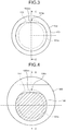
- FIG. 3 is a diagram as viewed from an arrow A illustrated in FIG. 2 .
- FIG. 4 is a cross sectional view associated with a line B-B illustrated in FIG. 2 .
- FIG. 2 illustrates a cross section associated with the cross sectional view of a balloon 111 taken along a line C-C illustrated in FIG. 3 in the state in which the balloon 111 is attached to the distal end portion 10a of the insertion portion 10 so as to cover the outer surface of the ultrasound transducer 100 (cross sectional view taken along a line D-D illustrated in FIG. 4 ).
- the ultrasound transducer 100 is provided at the distal end portion 10a that is located at the distal end of the insertion portion 10 to be inserted into the subject.
- a distal-end-side balloon groove 101 that is a balloon groove is provided on the distal end side of the ultrasound transducer 100.
- the proximal end side of the distal-end-side balloon groove 101 is constituted by a first wall surface that is a surface of a first wall portion 102 on the distal end side.
- the distal end side of the distal-end-side balloon groove 101 is constituted by the second wall surface that is a surface of a second wall portion 103 on the proximal end side.
- a proximal-end-side balloon groove 104 that is a balloon groove is provided on the proximal end side of the ultrasound transducer 100.
- the proximal end side of the proximal-end-side balloon groove 104 is constituted by the first wall surface that is a surface of a first wall portion 105 on the distal end side.
- the distal end side of the proximal-end-side balloon groove 104 is constituted by the second wall surface that is a surface of a second wall portion 106 on the proximal end side.
- the balloon 111 includes a main body 112 that covers the outer surface of the ultrasound transducer 100, a distal-end-side balloon band 113 that is provided on the distal end side of the main body 112, and a proximal-end-side balloon band 114 that is provided on the proximal end side of the main body 112. Then, the distal-end-side balloon band 113 is fitted into the distal-end-side balloon groove 101, whereas the proximal-end-side balloon band 114 is fitted into the proximal-end-side balloon groove 104.
- the ultrasound transducer 100 sends ultrasound into the subject and receives ultrasound (ultrasound echo) reflected in the subject.
- the outer circumference of the ultrasound transducer 100 is covered by the acoustic lens.
- the acoustic lens has a convex shape or a concave shape on one of the surfaces and has a function of diffusing ultrasound when externally emitting the ultrasound received from the ultrasound transducer 100 and extracting the ultrasound when acquiring the ultrasound received from outside into the ultrasound transducer 100.
- a contact portion 101a that constitutes the bottom surface of the distal-end-side balloon groove 101 and that is in contact with the distal-end-side balloon band 113 fitted into the distal-end-side balloon groove 101 has a circular shape.
- each of the directions from the center of the distal-end-side balloon groove 101 having a circular shape toward the outer side along the cross section orthogonal to the extension direction of the insertion portion 10 is referred to as a radial direction.
- the distance from the center to the outer circumference in each of the radial directions is referred to as a radius.
- a radius (a first distance) of a first wall surface of the first wall portion 102 is larger than a radius (a second distance) of the contact portion 101a of the distal-end-side balloon groove 101.
- the outer circumference of the first wall portion 102 has the same center as the contact portion 101a of the distal-end-side balloon groove 101 and has a circular shape with a larger radius than the contact portion 101a.
- the second wall portion 103 has, in each of the radial directions, a wall surface in which a radius (a third distance) of the second wall surface of the second wall portion 103 is larger than the radius (the second distance) of the contact portion 101a of the distal-end-side balloon groove 101. Furthermore, the second wall portion 103 has a notch portion 103a in a D-cut shape, the notch portion 103a being provided with a surface 103aa in which the radius (the third distance) of a one direction (upward along the plane of the drawing in FIG. 3 ) from among the radial directions is reduced.
- the radius (the third distance) of the surface 103aa of the notch portion 103a is equal to or greater than the radius of the contact portion 101a and is smaller than the radius of the second wall portion 103 in the direction in which the radius of the second wall portion 103 is the largest.
- a contact portion 104a that constitutes the bottom surface of the proximal-end-side balloon groove 104 and that is in contact with the proximal-end-side balloon band 114 fitted into the proximal-end-side balloon groove 104 has a circular shape.
- the radius (the first distance) of the first wall surface of the first wall portion 105 is larger than the radius of the contact portion 104a of the proximal-end-side balloon groove 104.
- outer circumference of the first wall portion 105 has the same center as the contact portion 104a of the proximal-end-side balloon groove 104 and has a circular shape with a larger radius than the contact portion 104a.
- the second wall portion 106 has, in each of the radial directions, a wall surface in which the radius (the third distance) of the second wall surface of the second wall portion 106 is larger than the radius (the second distance) of the contact portion 104a of the proximal-end-side balloon groove 104. Furthermore, the second wall portion 106 has a notch portion 106a in a D-cut shape, the notch portion 106a having a surface 106aa in which the radius (the third distance) of a one direction (upward along the plane of the drawing in FIG. 4 ) from among the radial directions is reduced.
- the radius (the third distance) of the surface 106aa of the notch portion 106a is equal to or greater than the radius of the contact portion 104a and is smaller than the radius of the second wall portion 106 in the direction in which the radius of the second wall portion 106 is the largest.
- a user inflates the main body 112 of the balloon 111 by introducing a small amount of liquid, such as water, into the balloon 111.
- a small amount of liquid such as water
- the user holds the main body 112 of the balloon 111 by the user's fingers and removes the proximal-end-side balloon band 114 that is fitted into the proximal-end-side balloon groove 104.
- the user pulls the held balloon 111 toward the distal end side and removes the distal-end-side balloon band 113 that is fitted into the distal-end-side balloon groove 101.
- the balloon 111 is broken and the distal-end-side balloon band 113 is left in the distal-end-side balloon groove 101.
- the ultrasound endoscope 2 it is possible to remove the distal-end-side balloon band 113 from the distal-end-side balloon groove 101 by using a tool with a sharp distal end, such as a toothpick.
- the user inserts the tool with the sharp distal end from the distal end side illustrated in FIG. 2 along the surface 103aa of the notch portion 103a of the second wall portion 103. Then, the distal end of the tool with the sharp distal end abuts against the surface of the first wall portion 102 on the distal end side.
- the user lifts the tool with the sharp distal end in a direction in which the tool with the sharp distal end away from the contact portion 101a of the distal-end-side balloon groove 101 (upward along the plane of the drawing in FIG. 2 ). Then, the user further pulls the tool with the sharp distal end toward for example, the distal end side in a state in which the distal-end-side balloon band 113 is caught by the tool with the sharp distal end and then removes the distal-end-side balloon band 113 from the distal-end-side balloon groove 101.
- the user can remove the distal-end-side balloon band 113 by the user's fingers from the state in which the distal-end-side balloon band 113 is caught by the tool with the sharp distal end or can cut the distal-end-side balloon band 113 by a pair of scissors, a scalpel, or the like.
- the ultrasound endoscope 2 is an ultrasound endoscope in which a balloon is easily removed.
- the distal end of the tool with the sharp distal end is prevented from being damaged caused by being brought into contact with the contact portion 101a of the distal-end-side balloon groove 101. If the contact portion 101a of the distal-end-side balloon groove 101 is damaged, leakage may sometimes occur when liquid, such as water, is introduced into the balloon 111 attached to the ultrasound endoscope 2.
- a radius of a portion of the first wall portion 102 across the distal-end-side balloon groove 101 from the notch portion 103a is larger than the radius of the notch portion 103a.
- the distal end of the tool with the sharp distal end that was inserted along the surface 103aa of the notch portion 103a of the second wall portion 103 abuts against the surface of the distal end side of the first wall portion 102. Consequently, the tool with the sharp distal end is prevented from being damaged caused by being brought into contact with the acoustic lens that covers the ultrasound transducer 100.
- the ultrasound endoscope 2 is an ultrasound endoscope in which the balloon is also easily removed on the proximal end side.
- the ultrasound endoscope 2 it is preferable to visually recognize the distal-end-side balloon band 113 fitted into the distal-end-side balloon groove 101 when viewing the distal end of the insertion portion 10 from the distal end side (direction of the arrow A illustrated in FIG. 2 ) of the extension direction of the insertion portion 10. If the distal-end-side balloon band 113 can be visually recognized, the tool with the sharp distal end can be easily inserted between the distal-end-side balloon band 113 and the distal-end-side balloon groove 101.
- the radius of the surface 103aa of the notch portion 103a be smaller than the sum of the radius of the contact portion 101a and the thickness of the distal-end-side balloon band 113.
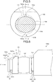
- FIG. 5 is a cross sectional view illustrating another example associated with the line B-B illustrated in FIG. 2 .
- the second wall portion 106 has an oval shape in cross section and has two notch portions 106a having surfaces 106aa in which radii (the third distance) of two directions (upward and downward along the plane of the drawing in FIG. 5 ) from among the radial directions are reduced.
- the surface 103aa of the notch portion 103a of the second wall portion 103 may also be reinforced because the surface 103aa is brought into contact with the tool with the sharp distal end. Furthermore, because the surface 103aa of the notch portion 103a of the second wall portion 103 and the tool with the sharp distal end slide each other, it is preferable to use a material having an excellent sliding property. In order to implement this, the surface 103aa of the notch portion 103a of the second wall portion 103 may also be coated by, for example, Teflon (registered trademark), fluorine, diamond, or the like. Furthermore, the surface 103aa of the notch portion 103a of the second wall portion 103 may also be formed of a material, such as hard titanium.
- FIG. 6 is a side view illustrating the configuration of a distal end portion of an insertion portion of an ultrasound endoscope according to a first modification of the embodiment.
- FIG. 7 is a diagram as viewed from an arrow E illustrated in FIG. 6 .
- the configuration of a distal end portion 10Aa of an ultrasound endoscope according to a first modification will be described with reference to FIG. 6 and FIG. 7 .
- a radius (the first distance) of a first wall surface of a first wall portion 102A that constitutes the proximal end side of the distal-end-side balloon groove 101 is larger than the radius (the second distance) of the contact portion 101a of the distal-end-side balloon groove 101.
- an outer circumference of the first wall portion 102A has the same center as the contact portion 101a of the distal-end-side balloon groove 101 and has a circular shape with a larger radius than the contact portion 101a.
- an inclined surface 102Aa in which a radius (the first distance) is decreased toward the distal end side along the extension direction of the insertion portion 10 is formed on the first wall portion 102A facing the notch portion 103a in the radial direction of the first wall portion 102A.
- the distal end of the tool with the sharp distal end that is inserted along the surface 103aa of the notch portion 103a of the second wall portion 103 moves forward along the inclined surface 102Aa of the first wall portion 102A. Consequently, the tool with the sharp distal end is prevented from being damaged caused by being brought into contact with the acoustic lens that covers the ultrasound transducer 100.
- the inclined surface 102Aa may also be connected to the distal-end-side balloon groove 101 by a smoothly curved surface.
- the ultrasound endoscope according to the first modification when removing the distal-end-side balloon band 113 that is left behind in the distal-end-side balloon groove 101, a user can remove the distal-end-side balloon band 113 from the distal-end-side balloon groove 101 without using any tool by sliding by using the user's fingers the distal-end-side balloon band 113 to the distal end side along the inclined surface 102Aa of the first wall portion 102A.
- each straight line in the case where, in a straight line group where each straight line is obtained by connecting an arbitrary point (for example, a point P1 in FIG. 6 ) on a front surface of the surface 103aa of the notch portion 103a and an arbitrary point (for example, a point P2 in FIG. 6 ) on a front surface of the first wall portion 102A, each straight line (for example, a straight line L in FIG.
- the straight line group 6 included in the straight line group is disposed so as not to intersect the first wall portion 102A and the second wall portion 103 except for the two points, it is preferable that a three-dimensionally spreading area through which the straight line group passes does not intersect the acoustic lens that covers the ultrasound transducer 100. The reason for this is to prevent the tool with the sharp distal end that has moved forward along the inclined surface 102Aa of the first wall portion 102A from being damaged caused by being brought into contact with the acoustic lens that covers the ultrasound transducer 100.
- FIG. 8 is a side view illustrating the configuration of a distal end portion of an insertion portion of an ultrasound endoscope according to a second modification of the embodiment.
- FIG. 9 is a diagram as viewed from an arrow F illustrated in FIG. 8 .
- the configuration of a distal end portion 10Ba of the ultrasound endoscope according to the second modification will be described with reference to FIG. 8 and FIG. 9 .
- a radius (the first distance) of a first wall surface of a first wall portion 102B that constitutes the proximal end side of the distal-end-side balloon groove 101 is larger than the radius (the second distance) of the contact portion 101a of the distal-end-side balloon groove 101.
- an outer circumference of the first wall portion 102B has the same center as the contact portion 101a of the distal-end-side balloon groove 101 and has a circular shape with a larger radius than the contact portion 101a.
- an inclined surface 102Ba in which a radius (the first distance) is decreased toward the distal end side along the extension direction of the insertion portion 10 is formed on the first wall portion 102B facing the notch portion 103a in the radial direction of the first wall portion 102B.
- the inclined surface 102Ba is formed around the entire circumference of the first wall portion 102B.
- the inclined surface 102Ba is connected to a cylindrical portion 102Bb having a constant radius along the extension direction of the insertion portion 10.
- the distal end of the tool with the sharp distal end inserted along the surface 103aa of the notch portion 103a of the second wall portion 103 moves ahead along the inclined surface 102Ba of the first wall portion 102B. Consequently, the tool with the sharp distal end is prevented from being damaged caused by being brought into contact with the acoustic lens that covers the ultrasound transducer 100.
- the inclined surface 102Ba may also be formed around the entire circumference of the radial direction.
- a notch portion is not formed on a second wall portion 106B of the distal end side of the proximal-end-side balloon groove 104. In this way, a notch portion may also be disposed on one side of the distal end side and proximal end side of the ultrasound transducer 100.
- FIG. 10 is a diagram illustrating the configuration of a distal end portion of an insertion portion according to another modification of the embodiment.
- FIG. 10 is a diagram of the ultrasound endoscope associated with FIG. 3 viewed from the distal end side.
- the notch portion 103a is not limited to the D-cut shape, but may also be, for example, a concave portion.
- a cutting instrument such as a pair of scissors, is not able to enter the notch portion 103a. Consequently, the contact portion 101a of the distal-end-side balloon groove 101 is prevented from being damaged by such a cutting instrument.
- the ultrasound endoscope having a radial type ultrasound transducer has been described; however, the embodiment is not limited to this.
- the embodiment can be applied to an ultrasound endoscope having a convex type ultrasound transducer.
Landscapes
- Health & Medical Sciences (AREA)
- Life Sciences & Earth Sciences (AREA)
- Surgery (AREA)
- Nuclear Medicine, Radiotherapy & Molecular Imaging (AREA)
- Medical Informatics (AREA)
- Pathology (AREA)
- Radiology & Medical Imaging (AREA)
- Engineering & Computer Science (AREA)
- Biomedical Technology (AREA)
- Heart & Thoracic Surgery (AREA)
- Physics & Mathematics (AREA)
- Molecular Biology (AREA)
- Biophysics (AREA)
- Animal Behavior & Ethology (AREA)
- General Health & Medical Sciences (AREA)
- Public Health (AREA)
- Veterinary Medicine (AREA)
- Optics & Photonics (AREA)
- Ultra Sonic Daignosis Equipment (AREA)
Abstract
Description
- The present invention relates to an ultrasound endoscope.
- Conventionally, there is a known method of performing observation, in an ultrasound endoscope having an ultrasound transducer at its distal end, by injecting deaerated water into a balloon that is disposed so as to cover an outer circumference of the ultrasound transducer and by bringing the balloon into close contact with an observed region, such as an alimentary canal (for example, see Patent Literature 1). In the ultrasound endoscope, balloon bands provided at both ends of the balloon are fitted into balloon grooves provided at the distal end of the ultrasound endoscope.
- With the ultrasound endoscope that performs observation by using such a balloon, the balloon needs to be removed from the ultrasound endoscope after the observation.
- Patent Literature 1: Japanese Laid-open Patent Publication No.
2006-204642 - With the conventional ultrasound endoscope, in some cases, it is difficult for a user to remove the balloon after observation because the balloon is in close contact with the ultrasound endoscope. In particular, in the case where only the balloon band has been left in the balloon groove, it is extremely difficult to remove the balloon.
- Accordingly, the present invention has been conceived in light of the circumstances described above, and an object thereof is to provide an ultrasound endoscope in which a balloon is easily removed.
- To solve the problem described above and to achieve the object, an ultrasound endoscope according to one aspect of the present invention includes: an ultrasound transducer that is provided at a distal end of an insertion portion configured to be inserted into a subject, the ultrasound transducer being configured to send ultrasound into the subject and receive the ultrasound reflected in the subject; a balloon groove that is provided on at least one side of a distal end side and a proximal end side of the ultrasound transducer and in which a balloon band is fitted, the balloon band being provided at an end portion of a balloon that is attached to cover an outer surface of the ultrasound transducer; a contact portion that constitutes a bottom surface of the balloon groove and that is in contact with the balloon band; a first wall portion that includes a first wall surface being a surface constituting the balloon groove on a ultrasound transducer side and in which a first distance that is a distance from a center of a cross section orthogonal to an extension direction of the insertion portion to an outer circumference of the first wall surface is larger than a second distance that is a distance from the center of the cross section to an outer circumference of the contact portion; and a second wall portion that includes a second wall surface being a surface constituting the balloon groove and facing the first wall surface, in which a third distance that is a distance from the center of the cross section to an outer circumference of the second wall surface is larger than the second distance, and that includes a notch portion provided with a surface in which a distance from the center of the cross section to the surface of the notch portion is larger than the second distance and is smaller than a distance in a direction in which the third distance is the largest.
- In the ultrasound endoscope according to one aspect of the present invention, the first distance of a portion of the first wall portion across the balloon groove from the notch portion is larger than a distance from the center of the cross section to an outer circumference of the surface that is formed on the notch portion.
- In the ultrasound endoscope according to one aspect of the present invention, the notch portion is formed on the second wall portion of a distal end side of the balloon groove provided on the distal end side of the ultrasound transducer.
- The ultrasound endoscope according to one aspect of the present invention, further includes an acoustic lens configured to cover an outer circumference of the ultrasound transducer. In a case where, in a straight line group where each straight line is obtained by connecting an arbitrary point on a front surface of the surface formed on the notch portion and an arbitrary point on a front surface of the first wall portion, each straight line in the straight line group is disposed so as not to intersect the first wall portion and the second wall portion except for the two points, the straight line group does not intersect the acoustic lens.
- In the ultrasound endoscope according to one aspect of the present invention, an inclined surface in which the first distance is decreased toward a distal end side along the extension direction of the insertion portion is formed on the first wall portion facing the notch portion in the cross section of the first wall portion.
- In the ultrasound endoscope according to one aspect of the present invention, the inclined surface is formed on the entire circumference of the first wall portion.
- In the ultrasound endoscope according to one aspect of the present invention, when the distal end of the insertion portion is viewed from a distal end side of the extension direction of the insertion portion, the balloon band that is fitted into the balloon groove can be visually recognized.
- According to an aspect of the present invention, it is possible to implement an ultrasound endoscope in which a balloon is easily removed.
-
-
FIG. 1 is a schematic view illustrating an ultrasound endoscope system that includes an ultrasound endoscope according to an embodiment of the present invention. -
FIG. 2 is a side view illustrating the configuration of a distal end portion of an insertion portion of the ultrasound endoscope illustrated inFIG. 1 . -
FIG. 3 is a diagram as viewed from an arrow A illustrated inFIG. 2 . -
FIG. 4 is a cross sectional view associated with a line B-B illustrated inFIG. 2 . -
FIG. 5 is a cross sectional view illustrating another example associated with the line B-B illustrated inFIG. 2 . -
FIG. 6 is a side view illustrating the configuration of a distal end portion of an insertion portion of an ultrasound endoscope according to a first modification of the embodiment. -
FIG. 7 is a diagram as viewed from an arrow E illustrated inFIG. 6 . -
FIG. 8 is a side view illustrating the configuration of a distal end portion of an insertion portion of an ultrasound endoscope according to a second modification of the embodiment. -
FIG. 9 is a diagram as viewed from an arrow F illustrated inFIG. 8 . -
FIG. 10 is a diagram illustrating the configuration of a distal end portion of an insertion portion according to another modification of the embodiment. - Preferred embodiments of an ultrasound endoscope according to the present invention will be explained with reference to accompanying drawings. Furthermore, the present invention is not limited to the embodiments. In the embodiments described below, an ultrasound endoscope in which a balloon groove is formed on both the proximal end side and the distal end side of an ultrasound transducer is described as an example; however, the ultrasound endoscope according to the present invention can be applied to a typically used ultrasound endoscope in which a balloon groove is formed and also applied to an ultrasound endoscope in which, for example, a balloon groove is formed only on the proximal end side of an ultrasound transducer.
- In the drawings, components that are identical to those in embodiments are assigned the same reference numerals. The drawings used for the descriptions below are only schematic illustrations. The relationship between the thickness and the width of each member, the proportions of each member, and so on are different from those used in practice. The size or reduction in scale of elements may sometimes differ between the drawings.
-
FIG. 1 is a schematic view illustrating an ultrasound endoscope system that includes an ultrasound endoscope according to an embodiment of the present invention. Anultrasound endoscope system 1 illustrated inFIG. 1 includes anultrasound endoscope 2, anendoscope observation apparatus 3, anultrasound observation apparatus 4, adisplay device 5, a light source device 6, avideo cable 7 that connects theultrasound endoscope 2 and theendoscope observation apparatus 3, an ultrasound cable 8 that connects theultrasound endoscope 2 and theultrasound observation apparatus 4, and alight source cable 9 that connects theultrasound endoscope 2 and the light source device 6. - The
ultrasound endoscope 2 is formed by combining an endoscope observation unit, which has observation optical system constituted by lenses or the like and has an image sensor, and an ultrasound transducer and has an endoscope observation function and an ultrasound measurement function. Theendoscope observation apparatus 3 controls the endoscope observation function and processes an output signal that is output from theultrasound endoscope 2 obtained from endoscope observation. Theultrasound observation apparatus 4 controls the ultrasound measurement function and processes an output signal that is output from theultrasound endoscope 2 obtained from ultrasound measurement. Thedisplay device 5 acquires signals output from, for example, theendoscope observation apparatus 3 and theultrasound observation apparatus 4 and appropriately displays at least one of an endoscope image and an ultrasound tomogram. The light source device 6 includes a light source for supplying illumination light that is used to perform endoscope observation. - The
ultrasound endoscope 2 includes aninsertion portion 10 that is inserted into the body, that sends an ultrasound signal into the subject, and that receives the ultrasound signal reflected in the subject; anoperating unit 11 that is consecutively provided on the proximal end side of theinsertion portion 10; and anuniversal cable 12 extended from a side portion of theoperating unit 11. Theuniversal cable 12 includes aconnector portion 13 that is provided on the end portion located on the different side from theoperating unit 11 side and that is connected to each of thevideo cable 7, the ultrasound cable 8, and thelight source cable 9. - The
insertion portion 10 is formed by consecutively connecting, in the order from the distal end side, adistal end portion 10a that is provided with anultrasound transducer 100, which will be described later; abending portion 10b that is formed so as to be freely bendable; and aflexible tube portion 10c that has flexibility. The proximal end of theflexible tube portion 10c is consecutively connected on the distal end side of theoperating unit 11. Furthermore, in the present specification, the distal end side along the direction in which theinsertion portion 10 is inserted (an upper part along the plane of the drawing inFIG. 1 ) is referred to as a distal end side and the proximal end side along the direction in which theinsertion portion 10 is inserted (a lower part along the plane of the drawing inFIG. 1 ) is referred to as a proximal end side. - A treatment
instrument insertion port 11a that is used to introduce a puncture needle or the like that is a treatment instrument is provided in theoperating unit 11. A treatment instrument insertion path is provided inside theinsertion portion 10 and the treatmentinstrument insertion port 11a functions as an insertion port of the treatment instrument insertion path. - Both the
ultrasound endoscope 2 and theendoscope observation apparatus 3 are electrically connected by thevideo cable 7 that is connected to theconnector portion 13. Both theultrasound endoscope 2 and anultrasound observation apparatus 4 are electrically connected by the ultrasound cable 8 that is connected to theconnector portion 13. Thelight source cable 9 is an optical fiber cable and both theultrasound endoscope 2 and the light source device 6 introduce, to theultrasound endoscope 2, illumination light emitted from a light source of the light source device 6 by thelight source cable 9 that is connected to theconnector portion 13. -
FIG. 2 is a side view illustrating the configuration of the distal end portion of the insertion portion of the ultrasound endoscope illustrated inFIG. 1 .FIG. 3 is a diagram as viewed from an arrow A illustrated inFIG. 2 .FIG. 4 is a cross sectional view associated with a line B-B illustrated inFIG. 2 . Furthermore,FIG. 2 illustrates a cross section associated with the cross sectional view of aballoon 111 taken along a line C-C illustrated inFIG. 3 in the state in which theballoon 111 is attached to thedistal end portion 10a of theinsertion portion 10 so as to cover the outer surface of the ultrasound transducer 100 (cross sectional view taken along a line D-D illustrated inFIG. 4 ). - As illustrated in
FIG. 2 , theultrasound transducer 100 is provided at thedistal end portion 10a that is located at the distal end of theinsertion portion 10 to be inserted into the subject. A distal-end-side balloon groove 101 that is a balloon groove is provided on the distal end side of theultrasound transducer 100. The proximal end side of the distal-end-side balloon groove 101 is constituted by a first wall surface that is a surface of afirst wall portion 102 on the distal end side. The distal end side of the distal-end-side balloon groove 101 is constituted by the second wall surface that is a surface of asecond wall portion 103 on the proximal end side. Furthermore, a proximal-end-side balloon groove 104 that is a balloon groove is provided on the proximal end side of theultrasound transducer 100. The proximal end side of the proximal-end-side balloon groove 104 is constituted by the first wall surface that is a surface of afirst wall portion 105 on the distal end side. The distal end side of the proximal-end-side balloon groove 104 is constituted by the second wall surface that is a surface of asecond wall portion 106 on the proximal end side. - The
balloon 111 includes amain body 112 that covers the outer surface of theultrasound transducer 100, a distal-end-side balloon band 113 that is provided on the distal end side of themain body 112, and a proximal-end-side balloon band 114 that is provided on the proximal end side of themain body 112. Then, the distal-end-side balloon band 113 is fitted into the distal-end-side balloon groove 101, whereas the proximal-end-side balloon band 114 is fitted into the proximal-end-side balloon groove 104. - The
ultrasound transducer 100 sends ultrasound into the subject and receives ultrasound (ultrasound echo) reflected in the subject. The outer circumference of theultrasound transducer 100 is covered by the acoustic lens. The acoustic lens has a convex shape or a concave shape on one of the surfaces and has a function of diffusing ultrasound when externally emitting the ultrasound received from theultrasound transducer 100 and extracting the ultrasound when acquiring the ultrasound received from outside into theultrasound transducer 100. - As illustrated in
FIG. 3 , acontact portion 101a that constitutes the bottom surface of the distal-end-side balloon groove 101 and that is in contact with the distal-end-side balloon band 113 fitted into the distal-end-side balloon groove 101 has a circular shape. Furthermore, in the present specification, each of the directions from the center of the distal-end-side balloon groove 101 having a circular shape toward the outer side along the cross section orthogonal to the extension direction of theinsertion portion 10 is referred to as a radial direction. Furthermore, the distance from the center to the outer circumference in each of the radial directions is referred to as a radius. - In each of the radial directions, a radius (a first distance) of a first wall surface of the
first wall portion 102 is larger than a radius (a second distance) of thecontact portion 101a of the distal-end-side balloon groove 101. Namely, the outer circumference of thefirst wall portion 102 has the same center as thecontact portion 101a of the distal-end-side balloon groove 101 and has a circular shape with a larger radius than thecontact portion 101a. - The
second wall portion 103 has, in each of the radial directions, a wall surface in which a radius (a third distance) of the second wall surface of thesecond wall portion 103 is larger than the radius (the second distance) of thecontact portion 101a of the distal-end-side balloon groove 101. Furthermore, thesecond wall portion 103 has anotch portion 103a in a D-cut shape, thenotch portion 103a being provided with a surface 103aa in which the radius (the third distance) of a one direction (upward along the plane of the drawing inFIG. 3 ) from among the radial directions is reduced. The radius (the third distance) of the surface 103aa of thenotch portion 103a is equal to or greater than the radius of thecontact portion 101a and is smaller than the radius of thesecond wall portion 103 in the direction in which the radius of thesecond wall portion 103 is the largest. - As illustrated in
FIG. 4 , acontact portion 104a that constitutes the bottom surface of the proximal-end-side balloon groove 104 and that is in contact with the proximal-end-side balloon band 114 fitted into the proximal-end-side balloon groove 104 has a circular shape. - In each of the radial directions, the radius (the first distance) of the first wall surface of the
first wall portion 105 is larger than the radius of thecontact portion 104a of the proximal-end-side balloon groove 104. Namely, outer circumference of thefirst wall portion 105 has the same center as thecontact portion 104a of the proximal-end-side balloon groove 104 and has a circular shape with a larger radius than thecontact portion 104a. - The
second wall portion 106 has, in each of the radial directions, a wall surface in which the radius (the third distance) of the second wall surface of thesecond wall portion 106 is larger than the radius (the second distance) of thecontact portion 104a of the proximal-end-side balloon groove 104. Furthermore, thesecond wall portion 106 has anotch portion 106a in a D-cut shape, thenotch portion 106a having a surface 106aa in which the radius (the third distance) of a one direction (upward along the plane of the drawing inFIG. 4 ) from among the radial directions is reduced. The radius (the third distance) of the surface 106aa of thenotch portion 106a is equal to or greater than the radius of thecontact portion 104a and is smaller than the radius of thesecond wall portion 106 in the direction in which the radius of thesecond wall portion 106 is the largest. - In the following, an operation performed when the
balloon 111 is removed from theultrasound endoscope 2 will be described. First, a user inflates themain body 112 of theballoon 111 by introducing a small amount of liquid, such as water, into theballoon 111. In this state, the user holds themain body 112 of theballoon 111 by the user's fingers and removes the proximal-end-side balloon band 114 that is fitted into the proximal-end-side balloon groove 104. Furthermore, the user pulls the heldballoon 111 toward the distal end side and removes the distal-end-side balloon band 113 that is fitted into the distal-end-side balloon groove 101. At this time, in some cases, theballoon 111 is broken and the distal-end-side balloon band 113 is left in the distal-end-side balloon groove 101. - Here, in the
ultrasound endoscope 2, it is possible to remove the distal-end-side balloon band 113 from the distal-end-side balloon groove 101 by using a tool with a sharp distal end, such as a toothpick. The user inserts the tool with the sharp distal end from the distal end side illustrated inFIG. 2 along the surface 103aa of thenotch portion 103a of thesecond wall portion 103. Then, the distal end of the tool with the sharp distal end abuts against the surface of thefirst wall portion 102 on the distal end side. Subsequently, the user lifts the tool with the sharp distal end in a direction in which the tool with the sharp distal end away from thecontact portion 101a of the distal-end-side balloon groove 101 (upward along the plane of the drawing inFIG. 2 ). Then, the user further pulls the tool with the sharp distal end toward for example, the distal end side in a state in which the distal-end-side balloon band 113 is caught by the tool with the sharp distal end and then removes the distal-end-side balloon band 113 from the distal-end-side balloon groove 101. Alternatively, the user can remove the distal-end-side balloon band 113 by the user's fingers from the state in which the distal-end-side balloon band 113 is caught by the tool with the sharp distal end or can cut the distal-end-side balloon band 113 by a pair of scissors, a scalpel, or the like. - As described above, because the
notch portion 103a is formed on thesecond wall portion 103, the tool with the sharp distal end is easily inserted between the distal-end-side balloon band 113 and the distal-end-side balloon groove 101; therefore, theultrasound endoscope 2 is an ultrasound endoscope in which a balloon is easily removed. - Furthermore, with the
ultrasound endoscope 2, because the tool with the sharp distal end is inserted along the surface 103aa of thenotch portion 103a of thesecond wall portion 103, the distal end of the tool with the sharp distal end is prevented from being damaged caused by being brought into contact with thecontact portion 101a of the distal-end-side balloon groove 101. If thecontact portion 101a of the distal-end-side balloon groove 101 is damaged, leakage may sometimes occur when liquid, such as water, is introduced into theballoon 111 attached to theultrasound endoscope 2. - Furthermore, in the
ultrasound endoscope 2, it is preferable that a radius of a portion of thefirst wall portion 102 across the distal-end-side balloon groove 101 from thenotch portion 103a is larger than the radius of thenotch portion 103a. In this case, the distal end of the tool with the sharp distal end that was inserted along the surface 103aa of thenotch portion 103a of thesecond wall portion 103 abuts against the surface of the distal end side of thefirst wall portion 102. Consequently, the tool with the sharp distal end is prevented from being damaged caused by being brought into contact with the acoustic lens that covers theultrasound transducer 100. - Furthermore, when the
balloon 111 is removed from theultrasound endoscope 2, the proximal-end-side balloon band 114 fitted into the proximal-end-side balloon groove 104 is sometimes left in the proximal-end-side balloon groove 104. Because thenotch portion 106a is also formed on thesecond wall portion 106, the tool with the sharp distal end is easily inserted between the proximal-end-side balloon band 114 and the proximal-end-side balloon groove 104, theultrasound endoscope 2 is an ultrasound endoscope in which the balloon is also easily removed on the proximal end side. - Furthermore, in the
ultrasound endoscope 2, it is preferable to visually recognize the distal-end-side balloon band 113 fitted into the distal-end-side balloon groove 101 when viewing the distal end of theinsertion portion 10 from the distal end side (direction of the arrow A illustrated inFIG. 2 ) of the extension direction of theinsertion portion 10. If the distal-end-side balloon band 113 can be visually recognized, the tool with the sharp distal end can be easily inserted between the distal-end-side balloon band 113 and the distal-end-side balloon groove 101. Thus, it is preferable that the radius of the surface 103aa of thenotch portion 103a be smaller than the sum of the radius of thecontact portion 101a and the thickness of the distal-end-side balloon band 113. - Furthermore, in the
ultrasound endoscope 2, thesecond wall portion 103 and thesecond wall portion 106 have thenotch portion 103a and thenotch portion 106a, respectively, in a one direction from among the radial directions; however, notch portions may also be included in a plurality of directions in the radial directions.FIG. 5 is a cross sectional view illustrating another example associated with the line B-B illustrated inFIG. 2 . As illustrated inFIG. 5 , thesecond wall portion 106 has an oval shape in cross section and has twonotch portions 106a having surfaces 106aa in which radii (the third distance) of two directions (upward and downward along the plane of the drawing inFIG. 5 ) from among the radial directions are reduced. - Furthermore, in the
ultrasound endoscope 2, the surface 103aa of thenotch portion 103a of thesecond wall portion 103 may also be reinforced because the surface 103aa is brought into contact with the tool with the sharp distal end. Furthermore, because the surface 103aa of thenotch portion 103a of thesecond wall portion 103 and the tool with the sharp distal end slide each other, it is preferable to use a material having an excellent sliding property. In order to implement this, the surface 103aa of thenotch portion 103a of thesecond wall portion 103 may also be coated by, for example, Teflon (registered trademark), fluorine, diamond, or the like. Furthermore, the surface 103aa of thenotch portion 103a of thesecond wall portion 103 may also be formed of a material, such as hard titanium. -
FIG. 6 is a side view illustrating the configuration of a distal end portion of an insertion portion of an ultrasound endoscope according to a first modification of the embodiment.FIG. 7 is a diagram as viewed from an arrow E illustrated inFIG. 6 . The configuration of a distal end portion 10Aa of an ultrasound endoscope according to a first modification will be described with reference toFIG. 6 andFIG. 7 . - As illustrated in
FIG. 7 , in each of the radial directions, a radius (the first distance) of a first wall surface of afirst wall portion 102A that constitutes the proximal end side of the distal-end-side balloon groove 101 is larger than the radius (the second distance) of thecontact portion 101a of the distal-end-side balloon groove 101. Namely, an outer circumference of thefirst wall portion 102A has the same center as thecontact portion 101a of the distal-end-side balloon groove 101 and has a circular shape with a larger radius than thecontact portion 101a. Furthermore, an inclined surface 102Aa in which a radius (the first distance) is decreased toward the distal end side along the extension direction of theinsertion portion 10 is formed on thefirst wall portion 102A facing thenotch portion 103a in the radial direction of thefirst wall portion 102A. - In the ultrasound endoscope according to the first modification, the distal end of the tool with the sharp distal end that is inserted along the surface 103aa of the
notch portion 103a of thesecond wall portion 103 moves forward along the inclined surface 102Aa of thefirst wall portion 102A. Consequently, the tool with the sharp distal end is prevented from being damaged caused by being brought into contact with the acoustic lens that covers theultrasound transducer 100. Furthermore, the inclined surface 102Aa may also be connected to the distal-end-side balloon groove 101 by a smoothly curved surface. - Furthermore, in the ultrasound endoscope according to the first modification, when removing the distal-end-
side balloon band 113 that is left behind in the distal-end-side balloon groove 101, a user can remove the distal-end-side balloon band 113 from the distal-end-side balloon groove 101 without using any tool by sliding by using the user's fingers the distal-end-side balloon band 113 to the distal end side along the inclined surface 102Aa of thefirst wall portion 102A. - Furthermore, in the ultrasound endoscope according to the first modification, in the case where, in a straight line group where each straight line is obtained by connecting an arbitrary point (for example, a point P1 in
FIG. 6 ) on a front surface of the surface 103aa of thenotch portion 103a and an arbitrary point (for example, a point P2 inFIG. 6 ) on a front surface of thefirst wall portion 102A, each straight line (for example, a straight line L inFIG. 6 ) included in the straight line group is disposed so as not to intersect thefirst wall portion 102A and thesecond wall portion 103 except for the two points, it is preferable that a three-dimensionally spreading area through which the straight line group passes does not intersect the acoustic lens that covers theultrasound transducer 100. The reason for this is to prevent the tool with the sharp distal end that has moved forward along the inclined surface 102Aa of thefirst wall portion 102A from being damaged caused by being brought into contact with the acoustic lens that covers theultrasound transducer 100. -
FIG. 8 is a side view illustrating the configuration of a distal end portion of an insertion portion of an ultrasound endoscope according to a second modification of the embodiment.FIG. 9 is a diagram as viewed from an arrow F illustrated inFIG. 8 . The configuration of a distal end portion 10Ba of the ultrasound endoscope according to the second modification will be described with reference toFIG. 8 andFIG. 9 . - As illustrated in
FIG. 9 , in each of the radial directions, a radius (the first distance) of a first wall surface of a first wall portion 102B that constitutes the proximal end side of the distal-end-side balloon groove 101 is larger than the radius (the second distance) of thecontact portion 101a of the distal-end-side balloon groove 101. Namely, an outer circumference of the first wall portion 102B has the same center as thecontact portion 101a of the distal-end-side balloon groove 101 and has a circular shape with a larger radius than thecontact portion 101a. Furthermore, an inclined surface 102Ba in which a radius (the first distance) is decreased toward the distal end side along the extension direction of theinsertion portion 10 is formed on the first wall portion 102B facing thenotch portion 103a in the radial direction of the first wall portion 102B. The inclined surface 102Ba is formed around the entire circumference of the first wall portion 102B. The inclined surface 102Ba is connected to a cylindrical portion 102Bb having a constant radius along the extension direction of theinsertion portion 10. - In the ultrasound endoscope according to the second modification, the distal end of the tool with the sharp distal end inserted along the surface 103aa of the
notch portion 103a of thesecond wall portion 103 moves ahead along the inclined surface 102Ba of the first wall portion 102B. Consequently, the tool with the sharp distal end is prevented from being damaged caused by being brought into contact with the acoustic lens that covers theultrasound transducer 100. In this way, the inclined surface 102Ba may also be formed around the entire circumference of the radial direction. - Furthermore, in the ultrasound endoscope according to the second modification, a notch portion is not formed on a
second wall portion 106B of the distal end side of the proximal-end-side balloon groove 104. In this way, a notch portion may also be disposed on one side of the distal end side and proximal end side of theultrasound transducer 100. -
FIG. 10 is a diagram illustrating the configuration of a distal end portion of an insertion portion according to another modification of the embodiment.FIG. 10 is a diagram of the ultrasound endoscope associated withFIG. 3 viewed from the distal end side. As illustrated inFIG. 10 , thenotch portion 103a is not limited to the D-cut shape, but may also be, for example, a concave portion. By forming thenotch portion 103a as the concave portion illustrated inFIG. 10 , a cutting instrument, such as a pair of scissors, is not able to enter thenotch portion 103a. Consequently, thecontact portion 101a of the distal-end-side balloon groove 101 is prevented from being damaged by such a cutting instrument. - Furthermore, in the embodiment described above, the ultrasound endoscope having a radial type ultrasound transducer has been described; however, the embodiment is not limited to this. For example, the embodiment can be applied to an ultrasound endoscope having a convex type ultrasound transducer.
- Further advantages and modifications can be easily derived by those skilled in the art. Therefore, the invention in its broader aspect is not limited to the specific details and representative embodiments shown and described herein. Accordingly, various modifications may be made without departing from the spirit or scope of the general inventive concept as defined by the appended claims and their equivalents.
-
- 1
- ultrasound endoscope system
- 2
- ultrasound endoscope
- 3
- endoscope observation apparatus
- 4
- ultrasound observation apparatus
- 5
- display device
- 6
- light source device
- 7
- video cable
- 8
- ultrasound cable
- 9
- light source cable
- 10
- insertion portion
- 10a, 10Aa, 10Ba
- distal end portion
- 10b
- bending portion
- 10c
- flexible tube portion
- 11
- operating unit
- 11a
- treatment instrument insertion port
- 12
- universal cable
- 13
- connector portion
- 100
- ultrasound transducer
- 101
- distal-end-side balloon groove
- 101a, 104a
- contact portion
- 102, 102A, 102B, 105
- the first wall portion
- 102Aa, 102Ba
- inclined surface
- 102Bb
- cylindrical portion
- 103, 106, 106B
- the second wall portion
- 103a, 106a
- notch portion
- 103aa, 106aa
- surface
- 104
- proximal-end-side balloon groove
- 111
- balloon
- 112
- main body
- 113
- distal-end-side balloon band
- 114
- proximal-end-side balloon band
- L
- straight line
- P1, P2
- point
Claims (7)
- An ultrasound endoscope comprising:an ultrasound transducer that is provided at a distal end of an insertion portion configured to be inserted into a subject, the ultrasound transducer being configured to send ultrasound into the subject and receive the ultrasound reflected in the subject;a balloon groove that is provided on at least one side of a distal end side and a proximal end side of the ultrasound transducer and in which a balloon band is fitted, the balloon band being provided at an end portion of a balloon that is attached to cover an outer surface of the ultrasound transducer;a contact portion that constitutes a bottom surface of the balloon groove and that is in contact with the balloon band;a first wall portion that includes a first wall surface being a surface constituting the balloon groove on a ultrasound transducer side and in which a first distance that is a distance from a center of a cross section orthogonal to an extension direction of the insertion portion to an outer circumference of the first wall surface is larger than a second distance that is a distance from the center of the cross section to an outer circumference of the contact portion; anda second wall portion that includes a second wall surface being a surface constituting the balloon groove and facing the first wall surface, in which a third distance that is a distance from the center of the cross section to an outer circumference of the second wall surface is larger than the second distance, and that includes a notch portion provided with a surface in which a distance from the center of the cross section to the surface of the notch portion is larger than the second distance and is smaller than a distance in a direction in which the third distance is the largest.
- The ultrasound endoscope according to claim 1, wherein the first distance of a portion of the first wall portion across the balloon groove from the notch portion is larger than a distance from the center of the cross section to an outer circumference of the surface that is formed on the notch portion.
- The ultrasound endoscope according to claim 1 or 2, wherein the notch portion is formed on the second wall portion of a distal end side of the balloon groove provided on the distal end side of the ultrasound transducer.
- The ultrasound endoscope according to claim 3, further comprising an acoustic lens configured to cover an outer circumference of the ultrasound transducer, wherein
in a case where, in a straight line group where each straight line is obtained by connecting an arbitrary point on a front surface of the surface formed on the notch portion and an arbitrary point on a front surface of the first wall portion, each straight line in the straight line group is disposed so as not to intersect the first wall portion and the second wall portion except for the two points, the straight line group does not intersect the acoustic lens. - The ultrasound endoscope according to any one of claims 1 to 4, wherein an inclined surface in which the first distance is decreased toward a distal end side along the extension direction of the insertion portion is formed on the first wall portion facing the notch portion in the cross section of the first wall portion.
- The ultrasound endoscope according to claim 5, wherein the inclined surface is formed on the entire circumference of the first wall portion.
- The ultrasound endoscope according to claim 3, wherein, when the distal end of the insertion portion is viewed from a distal end side of the extension direction of the insertion portion, the balloon band that is fitted into the balloon groove can be visually recognized.
Applications Claiming Priority (2)
| Application Number | Priority Date | Filing Date | Title |
|---|---|---|---|
| JP2016040958 | 2016-03-03 | ||
| PCT/JP2016/078312 WO2017149815A1 (en) | 2016-03-03 | 2016-09-26 | Ultrasonic endoscope |
Publications (2)
| Publication Number | Publication Date |
|---|---|
| EP3424435A1 true EP3424435A1 (en) | 2019-01-09 |
| EP3424435A4 EP3424435A4 (en) | 2019-11-27 |
Family
ID=59743664
Family Applications (1)
| Application Number | Title | Priority Date | Filing Date |
|---|---|---|---|
| EP16892652.5A Withdrawn EP3424435A4 (en) | 2016-03-03 | 2016-09-26 | Ultrasonic endoscope |
Country Status (5)
| Country | Link |
|---|---|
| US (1) | US11259776B2 (en) |
| EP (1) | EP3424435A4 (en) |
| JP (1) | JP6203451B1 (en) |
| CN (1) | CN108697407B (en) |
| WO (1) | WO2017149815A1 (en) |
Families Citing this family (4)
| Publication number | Priority date | Publication date | Assignee | Title |
|---|---|---|---|---|
| US11627870B2 (en) * | 2018-01-05 | 2023-04-18 | Boston Scientific Scimed, Inc. | Fluorophore imaging devices, systems, and methods for an endoscopic procedure |
| WO2020044905A1 (en) * | 2018-08-27 | 2020-03-05 | 富士フイルム株式会社 | Ultrasound endoscope balloon, ultrasound endoscope equipped with same, and production method therefor |
| JP7403969B2 (en) * | 2019-04-15 | 2023-12-25 | オリンパス株式会社 | ultrasound endoscope |
| DE112021001873T5 (en) | 2020-03-26 | 2023-01-12 | Fujifilm Corporation | ULTRASONIC ENDOSCOPE |
Family Cites Families (21)
| Publication number | Priority date | Publication date | Assignee | Title |
|---|---|---|---|---|
| US5000185A (en) * | 1986-02-28 | 1991-03-19 | Cardiovascular Imaging Systems, Inc. | Method for intravascular two-dimensional ultrasonography and recanalization |
| JPH069608A (en) * | 1992-03-05 | 1994-01-18 | Chisso Corp | Optical recording element and optical display element |
| JP2601022Y2 (en) * | 1992-07-14 | 1999-11-02 | 旭光学工業株式会社 | Ultrasound diagnostic equipment |
| JP3696006B2 (en) * | 1999-10-18 | 2005-09-14 | オリンパス株式会社 | Ultrasound endoscope |
| JP3918594B2 (en) * | 2002-03-13 | 2007-05-23 | フジノン株式会社 | Ultrasonic inspection equipment |
| JP3877075B2 (en) * | 2004-01-28 | 2007-02-07 | 有限会社エスアールジェイ | Endoscope device |
| CN101103900B (en) * | 2004-01-30 | 2012-08-15 | 富士胶片株式会社 | Insert assisting appliance of endoscope and endoscope apparatus |
| JP3962999B2 (en) * | 2004-03-29 | 2007-08-22 | 有限会社エスアールジェイ | Endoscope device |
| JP3922284B2 (en) * | 2004-03-31 | 2007-05-30 | 有限会社エスアールジェイ | Holding device |
| JP4484044B2 (en) * | 2004-07-29 | 2010-06-16 | 富士フイルム株式会社 | Ultrasound endoscope |
| US7692364B2 (en) | 2004-09-16 | 2010-04-06 | Olympus Medical Systems Corporation | Ultrasonic probe |
| JP4373347B2 (en) | 2005-01-28 | 2009-11-25 | オリンパスメディカルシステムズ株式会社 | Ultrasonic endoscope apparatus and ultrasonic transducer array |
| JP4000485B2 (en) * | 2005-02-28 | 2007-10-31 | フジノン株式会社 | Endoscope device |
| JP4665262B2 (en) * | 2005-08-31 | 2011-04-06 | 富士フイルム株式会社 | Endoscope hood |
| US20070219446A1 (en) * | 2006-03-14 | 2007-09-20 | Niyazi Beyhan | System and apparatus for imaging and treating hollow body cavities |
| JP2008099745A (en) * | 2006-10-17 | 2008-05-01 | Olympus Medical Systems Corp | Ultrasound endoscope balloon removal device |
| US20140018732A1 (en) * | 2011-01-10 | 2014-01-16 | Spotlight Technology Partners Llc | Apparatus and Methods for Accessing and Treating a Body Cavity, Lumen, or Ostium |
| CN102198024A (en) * | 2011-01-30 | 2011-09-28 | 王嘉贤 | Intravascular stent |
| WO2012160892A1 (en) * | 2011-05-20 | 2012-11-29 | オリンパスメディカルシステムズ株式会社 | Ultrasonic endoscope |
| JP5253693B1 (en) * | 2011-12-08 | 2013-07-31 | オリンパスメディカルシステムズ株式会社 | Ultrasonic probe |
| CN104640507B (en) * | 2013-08-22 | 2017-04-19 | 奥林巴斯株式会社 | Ultrasound endoscope and ultrasound balloon for endoscope |
-
2016
- 2016-09-26 EP EP16892652.5A patent/EP3424435A4/en not_active Withdrawn
- 2016-09-26 JP JP2017508588A patent/JP6203451B1/en active Active
- 2016-09-26 CN CN201680083107.4A patent/CN108697407B/en active Active
- 2016-09-26 WO PCT/JP2016/078312 patent/WO2017149815A1/en not_active Ceased
-
2018
- 2018-08-30 US US16/117,056 patent/US11259776B2/en active Active
Also Published As
| Publication number | Publication date |
|---|---|
| CN108697407A (en) | 2018-10-23 |
| JPWO2017149815A1 (en) | 2018-03-08 |
| US11259776B2 (en) | 2022-03-01 |
| CN108697407B (en) | 2021-12-07 |
| US20190125305A1 (en) | 2019-05-02 |
| WO2017149815A1 (en) | 2017-09-08 |
| EP3424435A4 (en) | 2019-11-27 |
| JP6203451B1 (en) | 2017-09-27 |
Similar Documents
| Publication | Publication Date | Title |
|---|---|---|
| US11259776B2 (en) | Ultrasound endoscope with ultrasound transducer and balloon including a notch provided on outer circumference of distal wall | |
| EP3260050B1 (en) | Biopsy needle | |
| US11925313B2 (en) | Endoscope and endoscope system | |
| JP4648638B2 (en) | Endoscope | |
| JP6579601B2 (en) | Endoscope | |
| US10695029B2 (en) | Ultrasonic endoscope | |
| US20160278694A1 (en) | Device for Visual Vein Location | |
| US9867557B2 (en) | Probe | |
| JP6653668B2 (en) | Ultrasound endoscope | |
| AU2023203468B2 (en) | Endoscope assembly and endoscope system having the same | |
| WO2017217269A1 (en) | Endoscope | |
| US10660510B2 (en) | Liposuction cannula with imaging means | |
| CN111343895B (en) | endoscope | |
| TWI798854B (en) | Combined needle endoscope and endoscope system | |
| JP6523062B2 (en) | Endoscope device | |
| US10244924B2 (en) | Endoscope | |
| HK40025359B (en) | Endoscope | |
| HK40025359A (en) | Endoscope | |
| JP2013063326A (en) | Endoscope apparatus |
Legal Events
| Date | Code | Title | Description |
|---|---|---|---|
| STAA | Information on the status of an ep patent application or granted ep patent |
Free format text: STATUS: THE INTERNATIONAL PUBLICATION HAS BEEN MADE |
|
| PUAI | Public reference made under article 153(3) epc to a published international application that has entered the european phase |
Free format text: ORIGINAL CODE: 0009012 |
|
| STAA | Information on the status of an ep patent application or granted ep patent |
Free format text: STATUS: REQUEST FOR EXAMINATION WAS MADE |
|
| 17P | Request for examination filed |
Effective date: 20180926 |
|
| AK | Designated contracting states |
Kind code of ref document: A1 Designated state(s): AL AT BE BG CH CY CZ DE DK EE ES FI FR GB GR HR HU IE IS IT LI LT LU LV MC MK MT NL NO PL PT RO RS SE SI SK SM TR |
|
| AX | Request for extension of the european patent |
Extension state: BA ME |
|
| DAV | Request for validation of the european patent (deleted) | ||
| DAX | Request for extension of the european patent (deleted) | ||
| A4 | Supplementary search report drawn up and despatched |
Effective date: 20191029 |
|
| RIC1 | Information provided on ipc code assigned before grant |
Ipc: A61B 8/12 20060101AFI20191023BHEP Ipc: A61B 8/00 20060101ALI20191023BHEP Ipc: A61B 1/00 20060101ALI20191023BHEP |
|
| STAA | Information on the status of an ep patent application or granted ep patent |
Free format text: STATUS: THE APPLICATION IS DEEMED TO BE WITHDRAWN |
|
| 18D | Application deemed to be withdrawn |
Effective date: 20200603 |