EP3424231B1 - Verfahren und basisstation zur steuerung des benutzerdatenverkehrs zwischen der drahtlosen vorrichtung und einer lokalen cloud - Google Patents
Verfahren und basisstation zur steuerung des benutzerdatenverkehrs zwischen der drahtlosen vorrichtung und einer lokalen cloud Download PDFInfo
- Publication number
- EP3424231B1 EP3424231B1 EP16892826.5A EP16892826A EP3424231B1 EP 3424231 B1 EP3424231 B1 EP 3424231B1 EP 16892826 A EP16892826 A EP 16892826A EP 3424231 B1 EP3424231 B1 EP 3424231B1
- Authority
- EP
- European Patent Office
- Prior art keywords
- user data
- data traffic
- bearer
- base station
- indicator
- Prior art date
- Legal status (The legal status is an assumption and is not a legal conclusion. Google has not performed a legal analysis and makes no representation as to the accuracy of the status listed.)
- Active
Links
- 238000000034 method Methods 0.000 title claims description 49
- 230000009471 action Effects 0.000 description 62
- 238000004891 communication Methods 0.000 description 35
- 230000006870 function Effects 0.000 description 31
- 238000004590 computer program Methods 0.000 description 12
- 238000010586 diagram Methods 0.000 description 12
- 230000005540 biological transmission Effects 0.000 description 11
- 230000004048 modification Effects 0.000 description 10
- 238000012986 modification Methods 0.000 description 10
- 238000005516 engineering process Methods 0.000 description 6
- 238000007726 management method Methods 0.000 description 5
- 238000013507 mapping Methods 0.000 description 4
- 230000004044 response Effects 0.000 description 4
- 238000012546 transfer Methods 0.000 description 4
- 230000001413 cellular effect Effects 0.000 description 3
- 238000010295 mobile communication Methods 0.000 description 3
- 230000011664 signaling Effects 0.000 description 3
- 230000005641 tunneling Effects 0.000 description 3
- 230000006399 behavior Effects 0.000 description 2
- 239000000969 carrier Substances 0.000 description 2
- 230000003287 optical effect Effects 0.000 description 2
- 230000008569 process Effects 0.000 description 2
- CSRZQMIRAZTJOY-UHFFFAOYSA-N trimethylsilyl iodide Substances C[Si](C)(C)I CSRZQMIRAZTJOY-UHFFFAOYSA-N 0.000 description 2
- 241000760358 Enodes Species 0.000 description 1
- 230000004913 activation Effects 0.000 description 1
- 230000003190 augmentative effect Effects 0.000 description 1
- 230000008901 benefit Effects 0.000 description 1
- 230000010267 cellular communication Effects 0.000 description 1
- 230000008859 change Effects 0.000 description 1
- 230000001419 dependent effect Effects 0.000 description 1
- 230000003993 interaction Effects 0.000 description 1
- 230000007774 longterm Effects 0.000 description 1
- 238000012423 maintenance Methods 0.000 description 1
- 230000007246 mechanism Effects 0.000 description 1
- 238000012544 monitoring process Methods 0.000 description 1
- 238000005457 optimization Methods 0.000 description 1
- 238000012545 processing Methods 0.000 description 1
- 238000011144 upstream manufacturing Methods 0.000 description 1
Images


Classifications
-
- H—ELECTRICITY
- H04—ELECTRIC COMMUNICATION TECHNIQUE
- H04M—TELEPHONIC COMMUNICATION
- H04M15/00—Arrangements for metering, time-control or time indication ; Metering, charging or billing arrangements for voice wireline or wireless communications, e.g. VoIP
- H04M15/83—Notification aspects
- H04M15/85—Notification aspects characterised by the type of condition triggering a notification
- H04M15/852—Low balance or limit reached
-
- H—ELECTRICITY
- H04—ELECTRIC COMMUNICATION TECHNIQUE
- H04L—TRANSMISSION OF DIGITAL INFORMATION, e.g. TELEGRAPHIC COMMUNICATION
- H04L12/00—Data switching networks
- H04L12/02—Details
- H04L12/14—Charging, metering or billing arrangements for data wireline or wireless communications
-
- H—ELECTRICITY
- H04—ELECTRIC COMMUNICATION TECHNIQUE
- H04L—TRANSMISSION OF DIGITAL INFORMATION, e.g. TELEGRAPHIC COMMUNICATION
- H04L12/00—Data switching networks
- H04L12/02—Details
- H04L12/14—Charging, metering or billing arrangements for data wireline or wireless communications
- H04L12/1403—Architecture for metering, charging or billing
- H04L12/1407—Policy-and-charging control [PCC] architecture
-
- H—ELECTRICITY
- H04—ELECTRIC COMMUNICATION TECHNIQUE
- H04L—TRANSMISSION OF DIGITAL INFORMATION, e.g. TELEGRAPHIC COMMUNICATION
- H04L67/00—Network arrangements or protocols for supporting network services or applications
- H04L67/01—Protocols
- H04L67/10—Protocols in which an application is distributed across nodes in the network
- H04L67/1001—Protocols in which an application is distributed across nodes in the network for accessing one among a plurality of replicated servers
- H04L67/1004—Server selection for load balancing
- H04L67/1008—Server selection for load balancing based on parameters of servers, e.g. available memory or workload
-
- H—ELECTRICITY
- H04—ELECTRIC COMMUNICATION TECHNIQUE
- H04L—TRANSMISSION OF DIGITAL INFORMATION, e.g. TELEGRAPHIC COMMUNICATION
- H04L67/00—Network arrangements or protocols for supporting network services or applications
- H04L67/50—Network services
- H04L67/60—Scheduling or organising the servicing of application requests, e.g. requests for application data transmissions using the analysis and optimisation of the required network resources
- H04L67/63—Routing a service request depending on the request content or context
-
- H—ELECTRICITY
- H04—ELECTRIC COMMUNICATION TECHNIQUE
- H04M—TELEPHONIC COMMUNICATION
- H04M15/00—Arrangements for metering, time-control or time indication ; Metering, charging or billing arrangements for voice wireline or wireless communications, e.g. VoIP
- H04M15/82—Criteria or parameters used for performing billing operations
- H04M15/8214—Data or packet based
-
- H—ELECTRICITY
- H04—ELECTRIC COMMUNICATION TECHNIQUE
- H04M—TELEPHONIC COMMUNICATION
- H04M15/00—Arrangements for metering, time-control or time indication ; Metering, charging or billing arrangements for voice wireline or wireless communications, e.g. VoIP
- H04M15/83—Notification aspects
- H04M15/85—Notification aspects characterised by the type of condition triggering a notification
- H04M15/853—Calculate maximum communication time or volume
-
- H—ELECTRICITY
- H04—ELECTRIC COMMUNICATION TECHNIQUE
- H04M—TELEPHONIC COMMUNICATION
- H04M15/00—Arrangements for metering, time-control or time indication ; Metering, charging or billing arrangements for voice wireline or wireless communications, e.g. VoIP
- H04M15/88—Provision for limiting connection, or expenditure
-
- H—ELECTRICITY
- H04—ELECTRIC COMMUNICATION TECHNIQUE
- H04W—WIRELESS COMMUNICATION NETWORKS
- H04W36/00—Hand-off or reselection arrangements
- H04W36/0005—Control or signalling for completing the hand-off
- H04W36/0011—Control or signalling for completing the hand-off for data sessions of end-to-end connection
- H04W36/0022—Control or signalling for completing the hand-off for data sessions of end-to-end connection for transferring data sessions between adjacent core network technologies
-
- H—ELECTRICITY
- H04—ELECTRIC COMMUNICATION TECHNIQUE
- H04W—WIRELESS COMMUNICATION NETWORKS
- H04W4/00—Services specially adapted for wireless communication networks; Facilities therefor
- H04W4/24—Accounting or billing
-
- H—ELECTRICITY
- H04—ELECTRIC COMMUNICATION TECHNIQUE
- H04W—WIRELESS COMMUNICATION NETWORKS
- H04W76/00—Connection management
- H04W76/10—Connection setup
- H04W76/15—Setup of multiple wireless link connections
-
- H—ELECTRICITY
- H04—ELECTRIC COMMUNICATION TECHNIQUE
- H04W—WIRELESS COMMUNICATION NETWORKS
- H04W8/00—Network data management
- H04W8/02—Processing of mobility data, e.g. registration information at HLR [Home Location Register] or VLR [Visitor Location Register]; Transfer of mobility data, e.g. between HLR, VLR or external networks
- H04W8/08—Mobility data transfer
-
- H—ELECTRICITY
- H04—ELECTRIC COMMUNICATION TECHNIQUE
- H04W—WIRELESS COMMUNICATION NETWORKS
- H04W88/00—Devices specially adapted for wireless communication networks, e.g. terminals, base stations or access point devices
- H04W88/08—Access point devices
-
- H—ELECTRICITY
- H04—ELECTRIC COMMUNICATION TECHNIQUE
- H04M—TELEPHONIC COMMUNICATION
- H04M15/00—Arrangements for metering, time-control or time indication ; Metering, charging or billing arrangements for voice wireline or wireless communications, e.g. VoIP
- H04M15/82—Criteria or parameters used for performing billing operations
- H04M15/8207—Time based data metric aspects, e.g. VoIP or circuit switched packet data
Definitions
- Embodiments herein relate to a base station, a wireless device and methods therein. In particular, they relate to controlling user data traffic between the UE and a local cloud.
- Wireless devises for communication are also known as e.g. User Equipments (UEs), mobile terminals, wireless terminals and/or mobile stations.
- Wireless devises are enabled to communicate wirelessly in a communication network such as a mobile network, sometimes also referred to as a wireless communications system, a cellular radio system or cellular networks.
- the communication may be performed e.g. between two mobile terminals, between a mobile terminal and a regular telephone and/or between a mobile terminal and a server, such as server providing video streaming service, via a Radio Access Network (RAN) and possibly one or more core networks, comprised within the communications network.
- RAN Radio Access Network
- a RAN is part of a wireless telecommunication system. It implements a radio access technology and it resides between a wireless device such as a mobile phone, a computer, or any remotely controlled machine and provides connection with its Core Network (CN).
- CN Core Network
- Wireless devises may further be referred to as mobile telephones, cellular telephones, computers, or surf plates with wireless capability, just to mention some further examples.
- the wireless devises in the present context may be, for example, portable, pocket-storable, hand-held, computer-comprised, or vehicle-mounted mobile devices, enabled to communicate voice and/or data, via the RAN, with another entity, such as another wireless device or a server.
- Some cellular communications networks cover a geographical area which is divided into cell areas, wherein each cell area is served by a base station, e.g. a Radio Base Station (RBS), which sometimes may be referred to as e.g. eNodeB (eNB), NodeB, B node, Base Transceiver Station (BTS), or AP (Access Point), depending on the technology and terminology used.
- the base stations may be of different classes such as e.g. macro eNodeB, home eNodeB or pico base station, based on transmission power and thereby also cell size.
- a cell is the geographical area where radio coverage is provided by the base station at a base station site.
- One base station, situated on the base station site may serve one or several cells.
- each base station may support one or several communication technologies.
- the base stations communicate over the air interface operating on radio frequencies with the wireless devices within range of the base stations.
- the base stations and wireless devices involved in communication may also be referred to as transmitter-receiver pairs, where the respective transmitter and receiver in a pair may refer to a base station or a wireless device, depending on the direction of the communication.
- the expression Downlink (DL) is used for the transmission path from the base station to a mobile terminal
- UL Uplink
- Universal Mobile Telecommunications System is a third generation mobile communication system, which evolved from the Global System for Mobile Communications (GSM), and is intended to provide improved mobile communication services based on Wideband Code Division Multiple Access (WCDMA) technology.
- GSM Global System for Mobile Communications
- WCDMA Wideband Code Division Multiple Access
- UTRAN UMTS Terrestrial Radio Access Network
- the 3GPP has undertaken to evolve further the UTRAN and GSM based radio access network technologies.
- base stations which may be referred to as eNodeBs or even eNBs, may be directly connected to one or more core networks.
- Pre-paid and on-line charging is very important for customers buying pre-paid subscriptions for their user equipments.
- the services are paid in advanced for a given bucket size, and the service is valid until the quota of the bucket has been consumed.
- This is known solutions for people skilled in charging/billing systems.
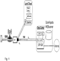
- the Local Cloud has a server that may provide high Quality of Experience (QoE) -streaming to the clients QOE-server, i.e. a local Content Distribution Network (CDN) server or a gaming server.
- QoE Quality of Experience
- CDN is a large distributed system of servers deployed in multiple data centers.
- a Protocol Proxy in the Local Cloud is used to interact with communication between the UE and the application server on Internet, and the Local cloud internal functions such as a QoE server that determines the best way how and when data is to be sent to the UE Terminal.
- An example of an application proxy a protocol proxy such as Transmission Control Protocol (TCP)- or Hypertext Transfer Protocol (HTTP) proxy that is extended with functions that also communicates with the network in order to determine how to achieve an optimal QoE delivery.
- TCP Transmission Control Protocol
- HTTP Hypertext Transfer Protocol
- a Hypervisor in the Local Cloud is used to allow virtualized functions to be deployed and run on the physical computing infrastructure in the Local Cloud.
- R in the Local Cloud is the site Router and it is used to establish a connection path to network node 10, i.e. to the S1-local-end-point function/black small box in the picture.
- S1U represents the GPRS Tunneling Protocol (GTP) Layer 2 tunneling user plane of the 3GPP defined S1 reference point and
- S1C is the control plane of the 3GPP defined S1 reference point that is used to set-up, remove GTP tunnels, as well as transferring mobility events and status in relation to the user terminal movements.
- GTP GPRS Tunneling Protocol
- a problem in a Mobile-Edge Architecture is that a complete core-network need to be deployed to support the charging function.
- One solution is to copy local traffic in a network node 10 that is located in the user plane path between the eNB and the Layer 2 GTP termination of S1 user plane reference point where all user data sent and received in a Radio Access Bearer (RAB) is copied to a more centralized core network where the charging function is located.
- the charging functions may be located in the Serving (S)/PDN (P) S/P-Gateway (GW), S or in a combined node.
- the charging systems may e.g. include Online Charging System (OCS) and Offline Charging System (OFCS).
- the Data Centre in Figure 1 represents a centrally located site where the core network and other network functions are deployed, such as Policy Control and Charging (PCC) functions that defines per user traffic enforcement rules that the PGW shall enforce, and if out of quota take appropriate action according the described policy, e.g. redirect of users traffic to an Out of quota WEB server.
- PCC Policy Control and Charging
- Both directions of the copied traffic is sent upstream so the S/P-GW detects the direction of the copied data such that the interfaces for Lawful Interception (LI) and charging act correctly on the copied streams and indicate appropriate direction to external LI-GW and Policy and Charging Control (PCC) functions.
- LI Lawful Interception
- PCC Policy and Charging Control
- Subscriptions are usually limited by data volume also referred to as data buckets, that the end-user can consume during e.g. a month, i.e. the transferred data volume e.g. in Mbytes over an access network.
- a byte-counter is shown as an entity for counting the consumed data volume for the user, i.e. the subscriber. It may be two different counters, one per direction.
- the user's traffic will be forced routed to Out-of-quota WEB-server.
- the WEB-server will inform the user that the quota is reached, i.e. bucket limit is reached, when the user requests a WEB-page on Internet.
- the breakout function to steer traffic to a Local Cloud may be based on 5-tuple, or parts of it, from the user data packet or be done on L2-parameters such as e.g. Packet Data Convergence Protocol (PDCP) or GPRS Tunneling Protocol (GTP) parameters.
- PDCP Packet Data Convergence Protocol
- GTP GPRS Tunneling Protocol
- S1-control parameters may be used to determine function of the local break-out function.
- S1 is a standardized interface between eNB, also referred to as base station, and the Evolved Packet Core (EPC).
- EPC Evolved Packet Core
- US 9071450 B22 discloses a system for charging and policy for services at the edge of a mobile data network. This document assumes that the optimization function has its own charging GW function. This means that it is multiplying the interfaces to the charging function. In this solution with multiple sources reporting charging data there is a coordination and management problem that require more work in configuring all interfaces and also functional extensions in the charging system to coordinate several sources reporting; in case the user is mobile.
- US 9173081 discloses a system and method for enabling interactions between a policy decision point and a charging system.
- This document relates to a system for managing group-based charging for network usage and spending in a communications network.
- a method may include receiving a charging event that identifies a user equipment from a charging component, applying the charging event, and determining whether the user equipment identified in the charging event is a member of the group of user equipment's identified in a subscription request.
- a problem with this solution is that the policy decision point that communicates with the charging system and policy decision point needs to be distributed. This solution will increase the complexity in data correlation that all distributed points have the same policy for a mobile user, i.e. it is an increased risk of errors.
- EP 2 538 719 A2 discloses a method performed by a base station for controlling user data traffic between a wireless device and a local cloud.
- Impact on lawful interception of Mobile Edge Computing describes a method to support lawful interception (LI) for Mobile Edge Computing (MEC) where uplink and downlink user traffic on the MEC platform is copied to the core network for processing by the existing LI systems.
- LI lawful interception
- MEC Mobile Edge Computing
- US20150156082A1 discloses a Service level agreement (SLA) based monitoring and configuration of a path for transmission of data that is achieved by identifying an SLA associated with the data and determining transmission requirements associated with the SLA.
- SLA Service level agreement
- the invention is defined by a method according to claim 1 and a base station according to claim 9. Further embodiments are defined by the dependent claims .
- Embodiments herein enable online charging control when local cloud deployments are done. This is since since an indicator is sent to the base station such that the base station is enabled to control user data traffic between the wireless device and a local cloud by setting up a split bearer from the base station.
- the split bearer comprises a first bearer to the local cloud.
- the bearer to the gateway node is kept as the second bearer. All user data traffic of the wireless device is routed to the local cloud over the first bearer and a copy is sent in to the gateway node to enable charging control of the traffic.
- a problem that embodiments herein address is to have minimal impact on 3GPP architecture in how to steer user data traffic towards a local cloud such as an Mobile Edge Cloud (MEC) node below the UE IP point of presence in the operators network, and how to disconnect traffic from MEC node.
- MEC Mobile Edge Cloud
- the main benefits to deploy applications on a MEC platform distributed in the network topology is to reduce latency for specific applications as augmented reality or scenarios for remote control of object, industry robots or in case of week and costly transport backhaul where pre-population of media servers in the MEC is done to give users high value user experience in those scenarios.
- MEC may also be referred to as Mobile Edge Computing.
- Another problem is that for on-line charging there is no solution for how traffic policies are enforced in the local cloud such as the MEC, e.g. how to redirect user data traffic due to out of data bucket quota, and how to do this without a major change of the 3GPP architecture, i.e. that is if not moving the S/PGW to the edge, which would drive an increased cost to have EPC distributed at many physical locations.
- MEC Mobility Management Entity
- MEC offers application developers and content providers cloud-computing capabilities and an IT service environment at the edge of a mobile network.
- MEC provides ultra-low latency and high bandwidth as well as real-time access to radio network information that may be leveraged by applications.
- operators can open their RAN edge to authorized third-parties, allowing them to flexibly and rapidly deploy applications and services towards mobile subscribers, enterprises and vertical segments.
- Embodiments herein relate to controlling charging for user data traffic to a local cloud.
- Embodiments herein enable online charging control below the UE IP point of presence in the operators network, also referred to as below a Packet Data Network GW (PDG) and below the Gi reference point, when local cloud deployments are done.
- Embodiments herein set for minimal changes to 3GPP architecture where an indicator such as e.g. a specific QCI value is used to set up a split bearer from the base station that sets up a first bearer to a local cloud, and at the same time keep the bearer to the gateway node such as an S1 bearer to S/P-GW, as a second bearer. All wireless device user data traffic is routed to the local cloud bearer and a copy is sent in the uplink direction to the gateway node such as the S/P-GW to enable charging control of the traffic.
- an indicator such as e.g. a specific QCI value
- a PDG Gi reference point is a IP routing point of UE IP packets and it is above the mobility anchor and IP point of presence for the wireless device. All bearers in 3GPP is layer 2 tunnels below the IP routing point, i.e. Gi.
- the reference point Gi lies between the Packet Data Network GW (PGW) and the external Packet Data Network (PDN). As an example, Gi lies between the PGW and external IP networks.
- GGSN is the GW for 2G-3G systems, from 4G EPC system it is called PGW.
- EPS bearer definition that is defined by Radio bearer, S1 Bearer(RBS to SGW) and a S5/S8 bearer (between SGW and PGW).
- S1 Bearer RBS to SGW
- S5/S8 bearer between SGW and PGW.
- Each node in 3GPP has an EPS bearer context description about the sub bearers described and other session related information including QCI.
- the split bearer has one more leg than any other bearer definitions.
- FIG. 2a depicts an example of a communications network 100 in which embodiments herein may be implemented.
- the communications network 100 may comprise any one or more out of: LTE, 5th generation mobile network (5G), GSM, GSM EDGE Radio Access Network (GERAN), Wi Fi, Wireless Local Area network (WLAN), WiMax, Code Divisional Multiple Access (CDMA) 2000, LTE-NX, Massive MIMO systems etc.
- EDGE is the abbreviation for Enhanced Data Rates for GSM Evolution
- LTE-NX means next-generation mobile radio access technology for 5G and future evolution of mobile systems access networks.
- the a communications network 100 comprises a radio access network 101 and a core network 102.
- the communications network 100 further comprises a local cloud 105.
- the local cloud 105 according to embodiments herein comprises a cloud infrastructure that may be deployed distributed in local areas close to or collocated with a cell site e.g. an RBS site such as the base station 110, an RBS Hub site or central office site.
- the central office site is typically a distributed site to local city areas where operators deploys telephony equipment and in this document also equal a distributed cloud data center.
- the local cloud 105 is a MEC
- the local cloud 105 may be collocated with some parts of the base station 110 such as e.g. in PDCP and S1-end-point termination function.
- S1 is the interface between a base station such as eNB and the core network node Mobility Management Entity (MME) and S-GW.
- MME Mobility Management Entity
- a plurality of network nodes operate in the radio access network 101 comprised in the wireless communications network 100 whereof one, a base station 110 is depicted in Figure 2 .
- the base station 110 may for example be an eNodeB, a NodeB, a Home Node B, a Home eNode B, a WiFi Access Point (AP), future evolved eNodeB or any other network node capable to serve a wireless device in a wireless communications network.
- AP WiFi Access Point
- One or more wireless devices are operable in the communications network 100, whereof one a wireless device 120 is shown in Figure 2a and 2b .
- wireless device when used herein may e.g. refer to a mobile terminal, a wireless device, a mobile wireless terminal or a wireless terminal, a mobile phone, a target device, a computer such as e.g. a laptop, a Personal Digital Assistants (PDAs) or an iPad, a tablet computer, sometimes referred to as a surf plate, with wireless capability, a smart phone, Laptop Embedded Equipment (LEE), Laptop Mounted Equipment (LME), Universal Serial Bus (USB) dongles or any other radio network units capable to communicate over a radio link in a wireless communications network.
- PDAs Personal Digital Assistants
- LME Laptop Mounted Equipment
- USB Universal Serial Bus
- a core network node 130 and a gateway node 140 operate in the core network 102.
- the core network node 130 may e.g. be an MME or Policy and Charging Rules Function (PCRF).
- the gateway node 140 may e.g. be a GGSN, SGSN, PGW and/or an SGW.
- the functionallity of base station 110 may comprise a termination point of the S1 reference point, referred to as an S1 local end-point control in this document.
- the function of the base station 110 such as e.g. the S1 end-point, according to some embodiments herein is that it implements a split-bearer function with the following behavior:
- the function of the gateway node 140 is that when a connection to the local cloud is established and all user data traffic on this first bearer is forwarded to the local cloud, and a copy of the packets are sent in the uplink direction of a second bearer, i.e. the other part of the split-bearer up to the gateway node 140 such as e.g. SGW and PGW, that will handle the wireless device 120 traffic according to a policy defined, e.g. bucket count and Charging Data Record (CDR) reporting to the charging system for the subscription related to the wireless device.
- CDR Charging Data Record
- a gateway policy such as a PGW policy, detects Out of quot" for this subscription related to the wireless device 120, a message such as an update bearer Request is sent to the core network node 130 such as the MEE to modify the Split bearer to a normal bearer e.g. as defined in a subscriber profile of the wireless device 120.
- the normal bearer is in the most cases a default bearer, but also another dedicated bearer with a different indicator, e.g. a different QCI value than local cloud 105 may be used.
- the function of the core network node 130 is to send indicators e.g. by sending a bearer modification request, comprising a QCI value that is same as, or different from the Local Cloud type, to the base station 110 indicating whether or not a user data traffic related to the wireless device shall be routed to the cloud 105. If the bearer modification request is successful the base station 110 may reply to the core network 102 such as the core network node 130 about the successful modification. In case of any error also that is reported to the core network node 130 that may try to make the bearer modification request once more or try to connect to an alternative access if available.
- An optional additional function in the gateway node 140 such as the PGW is to make an Uplink and Downlink mapping, referred to as UL/DL mapping in Figure 2b , so that copied packets are identified in the correct direction.
- UL/DL mapping Uplink and Downlink mapping
- All packets are in the UL direction so a re-mapping may be needed.
- For pure volume based charging where both UL and DL volume are merged there is no need to make a re-mapping of the directions, so it is not mandatory to always do remapping. But for Lawful Interception (LI) it may still be needed to do the remapping, but it also depending on how the LI solution is implemented, if LI reporting is done from the gateway node 140 such as PGW or from the local cloud 105 itself.
- LI Lawful Interception
- LI is a security process in which a service provider or network operator collects and provides law enforcement officials with intercepted communications of private individuals or organizations.
- a method for setting up bearers in a communications network 100 being congested is performed by the base station 110 and the core network node 130.
- DN Distributed Nodes
- functionality e.g. comprised in a cloud may be used for performing the methods.
- the PDN Gateway is an essential point in the network where charging, LI and mobility is anchored for each user attached in the communications network.
- the attachment procedure may comprise the message sequences when a user equipment such as the wireless device 130 detects a new network (e.g. after power on) the device will try to make connection (attach) to the network.
- a new network e.g. after power on
- the security keys between the UE and Network is exchanged and the subscriber identity is also authenticated if allowed to connect to the network. IP address of the device may also be sent to the UE during the attach procedure.
- an indicator such as a pre-defined 3GPP architecture parameter, e.g. a QCI value is used as a selection mechanism to detect that user data traffic shall be routed via a first bearer to the local cloud 105 which is below the UE IP point of presence in the operators network, and the user data traffic is copied into a second bearer 112 such as an EPS bearer in direction up to the gateway node such as e.g. PGW, i.e. a split bearer which may be a EPS split bearer.
- This new bearer may be pre-configured e.g.
- a dynamic bearer establishment is performed which may be UE initiated or network initiated, for a specified set of applications (APP)s that runs in the local cloud such as the MEC node.
- the network initiated request is according to current 3GPP specifications with one addition to use a specific parameter such as e.g. a different value on the QCI parameter so that the base station recognizes that this CQI value is different from other ordinary CQI values and makes use of that to detect and to redirect the user data traffic to the local cloud.
- HTTP Hypertext Transfer Protocol
- the Hypertext Transfer Protocol is an application protocol for distributed, collaborative, WEB based systems and is the foundation of data communication for the World Wide Web
- the HTTP GET method requests a representation of the specified resource used in the process to render a WEB page view visible for the end-user.
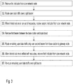
- Example embodiments of method performed by a base station 110, for controlling user data traffic between a wireless device 120 and a local cloud 105 will now be described with reference to a flowchart depicted in Figure 3 .
- the method will first be described in a more general way from the base station 110 perspective, and then from the core network node 130 perspective. The method will then be described more in detail and be exemplified further below.
- the wireless device 120 is associated with a limited volume of resources for user data traffic.
- the local cloud 105 is represented by a Mobile Edge Cloud.
- the local cloud 105 may be located below an UE IP point of presence in an operators network, which operator serves the wireless device 120.
- the user of the wireless device 120 may have purchased a pre-paid subscription for its wireless device 12, which subscription comprises a limited volume of resources for user data traffic.
- the wireless device 120 is thus associated to the limited volume of resources for user data traffic, which also may be referred to as configured for the limited volume of resources for user data traffic.
- Services are thus are paid in advanced for a given bucket size, i.e. limited volume of resources for user data traffic.
- the service is valid until the quota of the bucket has been consumed, i.e. until when the limited volume associated with the wireless device 120 is run out of resources.
- the base station 110 is capable of controlling the routing of user data traffic between a wireless device 120 and a local cloud 105.
- the base station 110 decides whether or not to route the user data traffic to the local cloud 105, which depends on whether it remains resources in the limited volume associated the wireless device 120 or if the wireless device 120 has consumed all resources in the limited volume.
- the decision whether or not to route the user data traffic to the local cloud 105 is based on an indicator such as the QCI value in a message from the core network node 130 such as e.g. an MME. In an exemplary scenario it remains resources in the limited volume when the wireless device 120 starts to send and receive user data traffic.
- the method comprises the following actions, which actions may be taken in any suitable order. Actions that are optional are presented in dashed boxes in Figure 3 .
- the base station 110 When it remains resources in the limited volume associated the wireless device 120, the base station 110 receives a first indicator from the core network node 130.
- the first indicator indicates that said user data traffic shall be routed to the local cloud 105.
- the first indicator may be comprised in a bearer context information.
- the first indicator may e.g. be represented by a QCI with a first value indicating that said user data traffic shall be routed to the local cloud 105 over the first bearer 111, and a copy said user data traffic shall be routed to the gateway node 140 over the second bearer 112.
- the base station 110 When the base station 110 has identified the indication of first indicator the base station 110 accordingly routes the user data traffic over a split bearer.
- the split bearer comprises a first bearer 111 between the base station 110 and the local cloud 105 in which said user data traffic is routed.
- the split bearer further comprises a second bearer 112 from the base station 110 to a gateway node 140.
- a copy of said user data traffic is routed. This is for measuring the volume of the user data traffic between the wireless device 120 and the local cloud 105 in relation to the limited volume for user data traffic associated with the wireless device 120.
- the user data traffic routed over the second bearer 112 from the base station 110 to the gateway node 140, may in some embodiments comprise a fourth indicator.
- the fourth indicator indicates whether or not this is copied user data traffic. So in this case the fourth indicator will indicate that this is a copy wireless device's user data traffic.
- This action is optional.
- all the resources in the limited volume are consumed during the ongoing user data traffic transmissions. This is detected by the gateway node 140 that reports it to the core network node 130 which in turn informs the base station by sending another indicator to the base station 110.
- the base station 110 When the limited volume associated with the wireless device 120 is run out of resources, the base station 110 receives a second indicator from the core network node 130.
- the second indicator indicates that the first bearer 111 between the base station 110 and the local cloud 105 shall be removed.
- the second indicator may be comprised in a bearer context information.
- the second indicator may e.g. be represented by a QCI with a second value indicating that the first bearer 111 between the base station 110 and the local cloud 105 shall be removed, and that the second bearer 112 shall remain.
- the base station 110 When the base station 110 has identified the indication of second indicator, the base station 110 accordingly removes the first bearer 111 between the base station 110 and the local cloud 105.
- the base station 110 may in some embodiments send an indication to the local cloud that the wireless device 120 has disconnected from the local could so that any application referred to as APP in Figure 2b , running in the local cloud 105 knows that wireless device 120 is not connected anymore. However, in some embodiments it is only a timeout in the application side.
- the base station 110 When the base station 110 has identified the indication of second indicator the base station 110 further routes remaining user data traffic only over the second bearer 112 from the base station 110 to the gateway node 140.
- the remaining user data traffic may in some embodiments comprise a fourth indicator.
- the fourth indicator indicates whether or not this is copied user data traffic. So in this case the fourth indicator will indicate that this is not a copy wireless device's user data traffic.
- the fourth indicator indicates that the user data traffic is not copied user data traffic.
- the base station 110 will implicitly know that that the remaining user data traffic on the second bearer 112 will not be further routed out from a core network.
- the fourth indicator may further indicate that the remaining user data traffic on the second bearer 112 will not be further routed out from a core network.
- the fourth indicator may be comprised in a bearer context information.
- the fourth indicator may e.g. be represented by a QCI with a fourth value indicating whether or not this is copied user data traffic.
- the user of the wireless device 120 refills resources e.g. by purchasing some more a pre-paid subscription for its wireless device 120, so that the subscription comprises a further limited volume of resources for user data traffic. This is detected by the core network node 130 which informs the base station 110 by sending a further indicator to the base station 110.
- the base station 110 receives a third indicator from the core network node 130.
- the third indicator indicates that the remaining user data traffic shall be re-routed to the local cloud 105.
- the third indicator may be comprised in a bearer context information.
- the third indicator may e.g. be represented by a QCI with the first value indicating that said user data traffic shall be routed to the local cloud 105.
- This action is optional. This action is optional.
- the base station 110 When the base station 110 has identified the indication of second indicator, the base station 110 accordingly re-routes the remaining user data traffic over the split bearer.
- the split bearer comprises a re-setup first bearer 111 between the base station 110 and the local cloud 105 in which said remaining user data traffic is routed.
- the split bearer further comprises said second bearer 112 from the base station 110 to the gateway node 140.
- the second bearer 112 a copy of said remaining user data traffic is routed. This is for measuring the volume of the user data traffic between the wireless device 120 and the local cloud 105 in relation to the limited volume of resources for user data traffic associated with the wireless device 120.
- the user data traffic routed over the second bearer 112 from the base station 110 to the gateway node 140, may in some embodiments comprise a fourth indicator.
- the fourth indicator indicates whether or not this is copied user data traffic. So in this case the fourth indicator will indicate that this is a copy wireless device's user data traffic.
- any one or more out of the first indicator, the second indicator, the third indicator and the fourth indicator may be comprised in a bearer context information such as e.g. when the indicator is an QCI.
- the bearer context information is build up in each node based on session control messages, for example Attach, Service request, Bearer modification, PDN connection request and release signalling sequences as defined in 3GPP.
- Example embodiments of a method performed by a core network node 130, for controlling user data traffic between a wireless device 120 and a local cloud 105, will now be described with reference to a flowchart depicted in Figure 4 .
- the wireless device 120 is associated with a limited volume of resources for user data traffic, the method comprising.
- the method comprises the following actions, which actions may be taken in any suitable order. Actions that are optional are presented in dashed boxes in Figure 4 .
- the user of the wireless device 120 may have purchased a pre-paid subscription for its wireless device 12, which subscription comprises the limited volume of resources for user data traffic.
- subscription comprises the limited volume of resources for user data traffic.
- it remains resources in the limited volume when the transmission of the user data traffic is initiated and the core network node 130 is notified accordingly.
- the core network node 130 obtains from the gateway node 140, information that it remains resources in the limited volume associated the wireless device 120,
- the base station 110 To enable the base station 110 to control the route the user data traffic between the wireless device 120 and the local cloud 105, the base station 110 is informed that it remains resources in the limited volume associated the wireless device 120. Therefore the core network node 130 sends the first indicator to the base station 110.
- the first indicator indicates that said user data traffic shall be routed to the local cloud 105.
- the indicator instructs the base station 110 to route the user data traffic over a split bearer.
- the split bearer comprises a first bearer 111 between the base station 110 and the local cloud 105 in which said user data traffic is routed.
- the split bearer further comprises a second bearer 112 from the base station 110 to the gateway node 140.
- a copy of said user data traffic is routed, for measuring the volume of the user data traffic between the wireless device 120 and the local cloud 105 in relation to the limited volume for user data traffic associated with the wireless device 120.
- the first indicator may be comprised in a bearer context information.
- the first indicator may e.g. be represented by a QCI with a first value indicating that said user data traffic shall be routed to the local cloud 105 over the first bearer 111, and a copy said user data traffic shall be routed to the gateway node 140 over the second bearer 112.
- the user data traffic routed over the second bearer 112 from the base station 110 to the gateway node 140, may in some embodiments comprise a fourth indicator.
- the fourth indicator indicates whether or not this is copied user data traffic. So in this case the fourth indicator will indicate that this is a copy wireless device's user data traffic.
- the core network node 130 therefore obtains from the gateway node 140, information that the limited volume associated with the wireless device 120 is run out of resources.
- the core network node 130 will in turn inform the base station 110 by sending another indicator to the base station 110. Therefore the core network node 130 sends a second indicator to the base station 110. The second indicator indicates that the first bearer 111 between the base station 110 and the local cloud 105 shall be removed.
- the second indicator instructs the base station 110 to remove the first bearer 111 between the base station 110 and the local cloud 105, and route the remaining user data traffic only over the second bearer 112 from the base station 110 to the Gateway node 140.
- the second indicator may be comprised in a bearer context information.
- the second indicator may e.g. be represented by a QCI with a second value indicating that the first bearer 111 between the base station 110 and the local cloud 105 shall be removed, and that the second bearer 112 shall remain.
- the remaining user data traffic may in some embodiments comprise a fourth indicator.
- the fourth indicator indicates whether or not this is copied user data traffic. So in this case the fourth indicator will indicate that this is not a copy wireless device's user data traffic.
- the fourth indicator indicates that the user data traffic is copied user data traffic.
- the base station 110 will implicitly know that that the remaining user data traffic on the second bearer 112 will not be further routed out from a core network.
- the fourth indicator may further indicate that the remaining user data traffic on the second bearer 112 will not be further routed out from a core network.
- the fourth indicator may be comprised in a bearer context information.
- the fourth indicator may e.g. be represented by a QCI with a fourth value indicating whether or not this is copied user data traffic.
- the user of the wireless device 120 refills resources e.g. by purchasing some more a pre-paid subscription for its wireless device 120, so that the subscription comprises a further limited volume of resources for user data traffic.
- This is detected by the core network node 130 which informs the base station 110 by sending a further indicator to the base station 110. It is detected e.g. by receiving the information from the charging system, alternative implementation may be done, but is not relevant for this document.
- the core network node 130 obtains from the gateway node 140, e.g. implicitly, information that the limited volume associated with the wireless device 120 is refilled with resources and that the received traffic is copied traffic from the split bearer connection to the local cloud 105.
- the core network 102 informs the RAN 101 and GW to setup a split bearer and when that is done the core network 102 gets an implicit indication that this is done. There may also be explicit 3GPP signalling as a response to the bearer modification request that the core network sends to setup the split bearer.
- the core network node 130 sends a third indicator to the base station 110.
- the third indicator indicates that the remaining user data traffic shall be re-routed to the local cloud 105.
- the third indicator instructs the base station 110 to re-route the remaining user data traffic over the split bearer.
- the split bearer comprises a re-setup first bearer 111 between the base station 110 and the local cloud 105 in which said remaining user data traffic is routed.
- the split bearer further comprises said second bearer 112 from the base station 110 to the Gateway node 140, in which second bearer 112 a copy of said remaining user data traffic is routed. This is for measuring the volume of the user data traffic between the wireless device 120 and the local cloud 105 in relation to the limited volume of resources for user data traffic associated with the wireless device 120.
- the third indicator may be comprised in a bearer context information.
- the third indicator may e.g. be represented by a QCI with the first value indicating that said user data traffic shall be routed to the local cloud 105.
- the user data traffic routed over the second bearer 112 from the base station 110 to the gateway node 140, may in some embodiments comprise a fourth indicator.
- the fourth indicator indicates whether or not this is copied user data traffic. So in this case the fourth indicator will indicate that this is a copy wireless device's user data traffic.
- any one or more out of the first indicator, the second indicator, the third indicator and the fourth indicator may be comprised in a bearer context information.
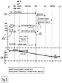
- FIG. 5 is a sequence diagram depicting an example of the method according to embodiments herein.
- the example scenario describes the wireless device 120 attaching to the network when subscriber profile is configured with QCI for the local cloud.
- the attach represent the initial attach to request connectivity to the communications network 100.
- the wireless device 120 referred to as UE in Figure 5-7 . initiates the Attach procedure by transmitting to the base station 110, referred to as eNB in Figure 5-7 , of an Attach Request message that is forwarded to the core network node 130 referred to as MME in Figure 5-7 , as described in TS 23.401.
- the core network node 130 e.g. the MME makes an authentication security procedure with a HSS. If OK the corer network node 130, e.g. the MEE sends an Update Location request to the HSS that replies with an "Update Location acknowledge" that holds the information of the "Subscription Data" comprising one or more PDN subscription contexts.
- the first indicator indicates that said user data traffic shall be routed to the local cloud 105. This relates to Actions 301, 401 and 402 above.
- the MME sends a session request to the SGW which is forwarded to PGW to establish the EPS bearer from the PGW and down to the eNB. If the Create session response is positive the MME sends an Initial connect setup and Attach except to configure the eNB side of the EPS bearer, network side and radio side.
- the QCI value does not need to be pre-defined in the HSS Subscriber data PDN connection context, as it can be provided explisit when a service is requested from an application system in the network .
- the differences is if the split-bearer shall be established at the wireless device 120 attach to have the bearer already established before a service request is done or if the split-bearer is set-up in a later stage when the service request is done from the wireless device 120 or from the core network as described above. If the subscriber is frequent user of local cloud deployed serves it is preferred to have the bearer established already at attach.
- the base station 110 e.g. eNB sends an RRC Connection Reconfiguration to the wireless device 120 to setup the radio bearer, which the first bearer 111.
- the second bearer to the gateway is already done in Action 502 at the message Create session request sent to SGW.
- the gateway node 140 e.g. SGW and PGW
- FIG. 6 is a sequence diagram depicting an example of the method according to embodiments herein.
- all the resources in the limited volume are consumed e.g. during the ongoing user data traffic transmissions, also referred to as the resources in the limited volume associated with the wireless device 120 is out of quota.
- This is detected by the gateway node 140 that reports it to the core network node 130 which in turn informs the base station by sending another indicator to the base station 110.
- Action 601. During the data plane phase when the user data traffic related to the wireless device 120 is copied to the gateway node 140, e.g. SGW and/or PGW and when the gateway policy, e.g.PGW policy detects "Out of quota" for this subscription, an update bearer Request is sent to the core network node 130, e.g. the MEE to modify the Split bearer to a normal bearer, as defined in subscriber profile , in the most cases a default bearer, but also another dedicated bearer with a different QCI value than LC may be used. This refers to action 403 above.
- the core network node 130 e.g. the MME sends a Bearer Modification request to the base station 110, e.g. the eNB and a normal RRC connection Configuration is sent by the base station 110 to the wireless device 120 to modify the bearer e.g. together with the second indicator, e.g. with QCI value corresponding to split bearer value, e.g. 169.
- This relates to Action 304 and 404.
- the base station 110 At reception of the RRC Connection Reconfiguration complete message, the base station 110 such as e.g. the S1 local end point of the base station 110 initiates a Remove split bearer message to the LC. This relates to Action 304.
- FIG. 7 is a sequence diagram depicting an example of the method according to embodiments herein.
- the user data traffic is not routed to the local cloud 105, but the user of the wireless device 120 refills resources e.g. by purchasing some more a pre-paid subscription for its wireless device 120, so that the subscription comprises a further limited volume of resources for user data traffic. This also referred to as new quota is added.
- This is detected by the core network node 130 which informs the base station 110 by sending a further indicator to the base station 110. It is possibly implementation used in that the WEB server sends this information to the core network and in that way the core network node 130 detects it.
- the core network node 130 may also ask for the status to detect.
- Action 702. When new quota is allocated, e.g. the user of the wireless device 120 makes an on-line payment of more quota, a WEB server will update the policy and charging rule functions in the system that sends an policy update to gateway node 140, e.g. the PGW with the new quota also referred to as new data bucket or resources of the limited volume is refilled.
- the gateway node 140 e.g. the PGW will check if the subscriber related to the wireless device 120 has the Split-bearer profile enabled and if so the gateway node 140, e.g. the PGW will send an Update Bearer Request to the core network node 130, e.g. the MME. This relates to Action 405.
- the base station such as the S1 local end point control function in the base station 110, sends a Create LC bearer, i.e. the first bearer 111, to the local cloud 105.
- Action 705. At reception of a positive Response message of the Create LC bearer the user data traffic of the user plane on that bearer will be routed over the first bearer 111 to the Local Cloud 105 and all user plane packets from and to the wireless device is copied in the uplink direction to the gateway node 140, e.g. the SGW/PGW on the second bearer 112, that will handle the user data traffic of the wireless device according to the policy defined, e.g. bucket count and CDR reporting. This relates to Action 307.
- the gateway node 140 e.g. the SGW/PGW on the second bearer 112
- the base station 110 may comprise the following arrangement depicted in Figure 8 .
- the wireless device 120 is configured to be associated with a limited volume of resources for user data traffic.
- the base station 110 is configured to, e.g. by means of a receiving module 810 configured to, when it remains resources in the limited volume associated the wireless device 120, receive a first indicator from a core network node 130.
- the first indicator is configured to indicates that said user data traffic shall be routed to the local cloud 105.
- the base station 110 is further configured to, e.g. by means of a routing module 820 configured to, route the user data traffic over a split bearer.
- the split bearer is configured to comprises a first bearer 111 between the base station 110 and the local cloud 105 in which said user data traffic is to be routed.
- the split bearer is further is configured to comprise a second bearer 112 from the base station 110 to a gateway node 140. In the second bearer 112, a copy of said user data traffic is to be routed for measuring the volume of the user data traffic between the wireless device 120 and the local cloud 105 in relation to the limited volume for user data traffic associated with the wireless device 120.
- the base station 110 may further be configured to, e.g. by means of the receiving module 810 configured to, when the limited volume associated with the wireless device 120 is run out of resources, receive a second indicator from the core network node 130.
- the second indicator is configured to indicate that the first bearer 111 between the base station 110 and the local cloud 105 shall be removed.
- the base station 110 may further be configured to, e.g. by means of a removing module 830 configured to, remove the first bearer 111 between the base station 110 and the local cloud 105.
- the base station 110 may further be configured to, e.g. by means of the routing module 820 configured to, route remaining user data traffic only over the second bearer 112 from the base station 110 to the gateway node 140.
- the base station 110 may further be configured to, e.g. by means of the receiving module 810 configured to, when the limited volume associated with the wireless device 120 is refilled with resources, receive a third indicator from the core network node 130.
- the third indicator is configured to indicate that the remaining user data traffic shall be re-routed to the local cloud 105.
- the base station 110 may further be configured to, e.g. by means of a re-routing module 840 configured to, re-route the remaining user data traffic over the split bearer.
- a re-routing module 840 configured to, re-route the remaining user data traffic over the split bearer.
- the split bearer is configured to comprise a re-setup first bearer 111 between the base station 110 and the local cloud 105 in which said remaining user data traffic is to be routed, and said second bearer 112 from the base station 110 to the gateway node 140.
- a copy of said remaining user data traffic is to be routed for measuring the volume of the user data traffic between the wireless device 120 and the local cloud 105 in relation to the limited volume of resources for user data traffic associated with the wireless device 120.
- the user data traffic or remaining user data traffic is to be routed over the second bearer 112 from the base station 110 to the gateway node 140.
- the user data traffic or remaining user data traffic may comprise a fourth indicator configured to indicate whether or not this is copied user data traffic.
- the fourth indicator may be configured to indicate that the user data traffic is not copied user data traffic, and wherein the fourth indicator further is configured to indicate that the remaining user data traffic on the second bearer 112 will not be further routed out from a core network.
- any one or more out of the first indicator, the second indicator, the third indicator and the fourth indicator may be comprised in a bearer context information.
- the local cloud 105 may be represented by a Mobile Edge Cloud.
- the local cloud 105 may be configured to be located below a User Equipment, UE, Internet Protocol, IP, point of presence in an operators network, which operator serves the wireless device 120.
- UE User Equipment
- IP Internet Protocol
- the embodiments herein may be implemented through one or more processors, such as a processor 850 in the base station 110 depicted in Figure 8 , together with computer program code for performing the functions and actions of the embodiments herein.
- the program code mentioned above may also be provided as a computer program product, for instance in the form of a data carrier carrying computer program code for performing the embodiments herein when being loaded into the base station 110 130.
- a data carrier carrying computer program code for performing the embodiments herein when being loaded into the base station 110 130.
- One such carrier may be in the form of a CD ROM disc. It is however feasible with other data carriers such as a memory stick.
- the computer program code may furthermore be provided as pure program code on a server and downloaded to the base station 110.
- the base station 110 may further comprise a memory 860 comprising one or more memory units.
- the memory 860 comprises instructions executable by the processor 850.
- the memory 860 is arranged to be used to store e.g. indicators, bearers set up for user data traffic, data, and configurations, to perform the methods herein when being executed in the base station 110.
- a computer program comprises instructions, which when executed by the at least one processor 850, cause the at least one processor 850 to perform actions according to any of the Actions 301-307.
- a carrier comprises the computer program, wherein the carrier is one of an electronic signal, an optical signal, an electromagnetic signal, a magnetic signal, an electric signal, a radio signal, a microwave signal, or a computer-readable storage medium.
- modules in the base station 110 may refer to a combination of analog and digital circuits, and/or one or more processors 850 configured with software and/or firmware, e.g. stored in the memory 860, that when executed by the one or more processors such as the processor 850 as described above.
- processors as well as the other digital hardware, may be included in a single Application-Specific Integrated Circuitry (ASIC), or several processors and various digital hardware may be distributed among several separate components, whether individually packaged or assembled into a system-on-a-chip (SoC).
- ASIC Application-Specific Integrated Circuitry
- SoC system-on-a-chip
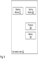
- core network node 130 may comprise the following arrangement depicted in Figure 9 .
- the wireless device 120 is associated with a limited volume of resources for user data traffic.
- the core network node 130 is configured to, e.g. by means of a obtaining module 910 configured to, obtain from a gateway node 140, information that it remains resources in the limited volume configured to be associated with the wireless device 120.
- the core network node 130 is further configured to, e.g. by means of a sending module 920 configured to, send a first indicator to the base station 110, which first indicator is configured to indicate that said user data traffic shall be routed to the local cloud 105, and which first indicator adapted to instructs the base station 110 to route the user data traffic over a split bearer.
- the split bearer is configured to comprise a first bearer 111 between the base station 110 and the local cloud 105 in which said user data traffic is to be routed.
- the split bearer further comprises a second bearer 112 from the base station 110 to the gateway node 140, in which second bearer 112 a copy of said user data traffic is to be routed, for measuring the volume of the user data traffic between the wireless device 120 and the local cloud 105 in relation to the limited volume for user data traffic configured to be associated with the wireless device 120.
- the core network node 130 may further be configured to, e.g. by means of the obtaining module 910 configured to, obtain from the gateway node 140, information that the limited volume configured to be associated with the wireless device 120 is run out of resources.
- the core network node 130 may further be configured to, e.g. by means of the sending module 920 configured to, send a second indicator to the base station 110, which second indicator is configured to indicate that the first bearer 111 between the base station 110 and the local cloud 105 shall be removed.
- the second indicator is configured to instruct the base station 110 to remove the first bearer 111 between the base station 110 and the local cloud 105, and route the remaining user data traffic only over the second bearer 112 from the base station 110 to the gateway node 140.
- the core network node 130 may further be configured to, e.g. by means of the obtaining module 910 configured to, when obtaining from the gateway node 140, information that the limited volume configured to be associated with the wireless device 120 is refilled with resources.
- the core network node 130 may further be configured to, e.g. by means of the sending module 920 configured to, send a third indicator to the base station 110, which third indicator is configured to indicate that the remaining user data traffic shall be re-routed to the local cloud 105.
- the third indicator is configured to instruct the base station 110 to re-route the remaining user data traffic over the split bearer.
- the split bearer is configured to comprise a re-setup first bearer 111 between the base station 110 and the local cloud 105 in which said remaining user data traffic is to be routed, and said second bearer 112 from the base station 110 to the gateway node 140.
- a copy of said remaining user data traffic is to be routed, for measuring the volume of the user data traffic between the wireless device 120 and the local cloud 105 in relation to the limited volume of resources for user data traffic configured to be associated with the wireless device 120.
- the user data traffic or remaining user data traffic is routed over the second bearer 112 from the base station 110 to the gateway node 140.
- the user data traffic or remaining user data traffic comprises a fourth indicator indicating whether or not this is copied user data traffic.
- the fourth indicator may be configured to indicate that the user data traffic is not copied user data traffic, and wherein the fourth indicator further is configured to indicate that the user data traffic on the second bearer 112 will not be further routed out from a core network of the core network node 130.
- any one or more out of the first indicator, the second indicator, the third indicator and the fourth indicator may be comprised in a bearer context information.
- the local cloud 105 may be represented by a Mobile Edge Cloud.
- the local cloud 105 may be configured to be located below a User Equipment, UE, Internet Protocol, IP, point of presence in an operators network, which operator serves the wireless device 120.
- UE User Equipment
- IP Internet Protocol
- the embodiments herein may be implemented through one or more processors, such as a processor 930 in the core network node 130 depicted in Figure 9 , together with computer program code for performing the functions and actions of the embodiments herein.
- the program code mentioned above may also be provided as a computer program product, for instance in the form of a data carrier carrying computer program code for performing the embodiments herein when being loaded into the core network node 130.
- a data carrier carrying computer program code for performing the embodiments herein when being loaded into the core network node 130.
- One such carrier may be in the form of a CD ROM disc. It is however feasible with other data carriers such as a memory stick.
- the computer program code may furthermore be provided as pure program code on a server and downloaded to the core network node 130.
- the core network node 130 may further comprise a memory 940 comprising one or more memory units.
- the memory 940 comprises instructions executable by the processor 930.
- the memory 940 is arranged to be used to store e.g. indicators, bearers set up for user data traffic, data, and configurations, to perform the methods herein when being executed in core network node 130.
- a computer program comprises instructions, which when executed by the at least one processor 930, cause the at least one processor 930 to perform actions according to any of the Actions 401-406.
- a carrier comprises the computer program, wherein the carrier is one of an electronic signal, an optical signal, an electromagnetic signal, a magnetic signal, an electric signal, a radio signal, a microwave signal, or a computer-readable storage medium.
- modules in the core network node 130 may refer to a combination of analog and digital circuits, and/or one or more processors 930 configured with software and/or firmware, e.g. stored in the memory 940, that when executed by the one or more processors such as the processor 930 as described above.
- processors 930 configured with software and/or firmware, e.g. stored in the memory 940, that when executed by the one or more processors such as the processor 930 as described above.
- One or more of these processors, as well as the other digital hardware may be included in a single Application-Specific Integrated Circuitry (ASIC), or several processors and various digital hardware may be distributed among several separate components, whether individually packaged or assembled into a system-on-a-chip (SoC).
- ASIC Application-Specific Integrated Circuitry
- SoC system-on-a-chip
- MEC Mobile Edge Computing
- MEC Mobile Edge Computing
- MME Mobility Management Entity
- MME Code MTC Machine-Type Communications
- M-TMSI M-Temporary Mobile Subscriber Identity
- OMC-ID Operation and Maintenance Centre Identity
- P GW PDN Gateway
- PCC Policy and Charging Control
- PCRF Policy and Charging Rules Function
- PRA Presence Reporting Area PDCP Packet Data Convergence Protocol
- QCI QoS Class Identifier
- S-TMSI S-Temporary Mobile Subscriber Identity
- SIPTO Selected IP Traffic Offload
- TAC Tracking Area Code TAD Traffic Aggregate Description
Landscapes
- Engineering & Computer Science (AREA)
- Computer Networks & Wireless Communication (AREA)
- Signal Processing (AREA)
- Computer Hardware Design (AREA)
- General Engineering & Computer Science (AREA)
- Business, Economics & Management (AREA)
- Accounting & Taxation (AREA)
- Databases & Information Systems (AREA)
- Mobile Radio Communication Systems (AREA)
Claims (15)
- Verfahren, das von einer Basisstation (110) zum Steuern des Benutzerdatenverkehrs zwischen einer drahtlosen Vorrichtung (120) und einer lokalen Cloud (105) durchgeführt wird; wobei die lokale Cloud einen mobilen Edge-Computing-Server umfasst, wobei die drahtlose Vorrichtung (120) einem begrenzten Volumen von Ressourcen für den Benutzerdatenverkehr zugeordnet ist, wobei das Verfahren Folgendes umfasst: wenn die Ressourcen in dem begrenzten Volumen verbleiben, das der drahtlosen Vorrichtung (120) zugeordnet ist, Empfangen (301) eines ersten Indikators von einem Kernnetzwerkknoten (130), wobei der erste Indikator einen Hinweis umfasst, dass der Benutzerdatenverkehr an die lokale Cloud (105) geleitet werden soll;
nach Identifizieren der Anzeige des ersten Indikators, Leiten (302) des Benutzerdatenverkehrs über einen geteilten Träger,
wobei der geteilte Träger einen ersten Träger (111) zwischen der Basisstation (110) und der lokalen Cloud (105) umfasst, in der der Benutzerdatenverkehr von der Basisstation geleitet wird, und
wobei der geteilte Träger ferner einen zweiten Träger (112) von der Basisstation (110) zu einem Gateway-Knoten (140) umfasst, wobei eine Kopie des Benutzerdatenverkehrs in dem zweiten Träger (112) von der Basisstation geleitet wird, um das Volumen des Benutzerdatenverkehrs zwischen der drahtlosen Vorrichtung (120) und der lokalen Cloud (105) in Bezug auf das begrenzte Volumen für den Benutzerdatenverkehr, der der drahtlosen Vorrichtung (120) zugeordnet ist, zu messen, wobei der erste Indikator durch eine Dienstgüten- (Quality of Service, QoS) Klassenkennung (QoS Class Identifier, QCI) dargestellt wird, wobei ein erster Wert anzeigt, dass der Benutzerdatenverkehr über den ersten Träger (111) zur lokalen Cloud (105) geleitet werden soll, und wobei eine Kopie des Benutzerdatenverkehrs über den zweiten Träger (112) zum Gateway-Knoten (140) geleitet wird. - Verfahren nach Anspruch 1, das ferner Folgendes umfasst:
wenn das der drahtlosen Vorrichtung (120) zugeordnete begrenzte Volumen keine Ressourcen mehr aufweist, Empfangen (303) eines zweiten Indikators vom Kernnetzwerkknoten (130), wobei der zweite Indikator anzeigt, dass der erste Träger (111) zwischen der Basisstation (110) und der lokalen Cloud (105) entfernt werden soll,
Entfernen (304) des ersten Trägers (111) zwischen der Basisstation (110) und der lokalen Cloud (105) und
Leiten (305) des verbleibenden Benutzerdatenverkehrs nur über den zweiten Träger (112) von der Basisstation (110) zum Gateway-Knoten (140). - Verfahren nach einem der Ansprüche 1 bis 2, das ferner Folgendes umfasst:wenn das dem drahtlosen Vorrichtung (120) zugeordnete begrenzte Volumen mit Ressourcen aufgefüllt wird, Empfangen (306) eines dritten Indikators vom Kernnetzwerkknoten (130), wobei dieser dritte Indikator anzeigt, dass der verbleibende Benutzerdatenverkehr an die lokale Cloud (105) umgeleitet werden soll;Umleiten (307) des verbleibenden Benutzerdatenverkehrs über den geteilten Träger,wobei der geteilte Träger Folgendes umfasst: einen neu eingerichteten ersten Träger (111) zwischen der Basisstation (110) und der lokalen Cloud (105), in der der verbleibende Benutzerdatenverkehr geleitet wird, und den zweiten Träger (112) von der Basisstation (110) zum Gateway-Knoten (140), wobei in dem zweiten Träger (112) eine Kopie des verbleibenden Benutzerdatenverkehrs geleitet wird, um das Volumen des Benutzerdatenverkehrs zwischen der drahtlosen Vorrichtung (120) und der lokalen Cloud (105) in Bezug auf das begrenzte Volumen von Ressourcen für den Benutzerdatenverkehr, der der drahtlosen Vorrichtung (120) zugeordnet ist, zu messen.
- Verfahren nach einem der Ansprüche 1 bis 3, wobei der Benutzerdatenverkehr oder der verbleibende Benutzerdatenverkehr über den zweiten Träger (112) von der Basisstation (110) zu dem Gateway-Knoten (140) geleitet wird und wobei der Benutzerdatenverkehr oder der verbleibende Benutzerdatenverkehr einen vierten Indikator umfasst, der anzeigt, ob dies kopierter Benutzerdatenverkehr ist oder nicht.
- Verfahren nach Anspruch 4, wobei der vierte Indikator anzeigt, dass der Benutzerdatenverkehr kein kopierter Benutzerdatenverkehr ist, und wobei der vierte Indikator ferner anzeigt, dass der verbleibende Benutzerdatenverkehr auf dem zweiten Träger (112) nicht weiter von einem Kernnetzwerk (102) geleitet wird.
- Verfahren nach einem der Ansprüche 1 bis 5, wobei:
der erste Indikator, der zweite Indikator, der dritte Indikator und/oder der vierte Indikator in einer Trägerkontextinformation enthalten sind. - Verfahren nach einem der Ansprüche 1 bis 6, wobei:der zweite Indikator, der durch eine QCI mit einem zweiten Wert dargestellt wird, anzeigt, dass der erste Träger (111) zwischen der Basisstation (110) und der lokalen Cloud (105) entfernt werden soll und dass der zweite Träger (112) verbleiben soll;der dritte Indikator durch eine QCI dargestellt wird, wobei der erste Wert anzeigt, dass der Benutzerdatenverkehr an die lokale Cloud (105) geleitet werden soll, und/oderder vierte Indikator durch eine QCI dargestellt wird, wobei ein vierter Wert anzeigt, ob dies ein kopierter Benutzerdatenverkehr ist oder nicht.
- Verfahren nach einem der Ansprüche 1 bis 7, das ferner Folgendes umfasst:Erhalten (401), durch den Kernnetzwerkknoten (130) von dem Gateway-Knoten (140), von Informationen, dass es Ressourcen in dem begrenzten Volumen behält, das der drahtlosen Vorrichtung (120) zugeordnet ist,Senden (402), durch den Kernnetzwerkknoten (130), des ersten Indikators an die Basisstation (110).
- Basisstation (110) zum Steuern des Benutzerdatenverkehrs zwischen einer drahtlosen Vorrichtung (120) und einer lokalen Cloud (105), wobei die lokale Cloud einen mobilen Edge-Computing-Server umfasst; wobei die drahtlose Vorrichtung (120) dafür konfiguriert ist, einem begrenzten Volumen von Ressourcen für den Benutzerdatenverkehr zugeordnet zu sein; wobei die Basisstation (110) für Folgendes konfiguriert ist:wenn die Ressourcen in dem begrenzten Volumen verbleiben, das der drahtlosen Vorrichtung (120) zugeordnet ist, Empfangen eines ersten Indikators von einem Kernnetzwerkknoten (130), wobei der erste Indikator einen Hinweis umfasst, dass der Benutzerdatenverkehr an die lokale Cloud (105) geleitet werden soll;nach Identifizieren der Anzeige des ersten Indikators, Leiten des Benutzerdatenverkehrs über einen geteilten Träger,wobei der geteilte Träger einen ersten Träger (111) zwischen der Basisstation (110) und der lokalen Cloud (105) umfasst, in dem der Benutzerdatenverkehr von der Basisstation geleitet werden soll, undwobei der geteilte Träger ferner einen zweiten Träger (112) von der Basisstation (110) zu einem Gateway-Knoten (140) umfasst, wobei eine Kopie des Benutzerdatenverkehrs in dem zweiten Träger (112) von der Basisstation geleitet wird, um das Volumen des Benutzerdatenverkehrs zwischen der drahtlosen Vorrichtung (120) und der lokalen Cloud (105) in Bezug auf das begrenzte Volumen für den Benutzerdatenverkehr, der der drahtlosen Vorrichtung (120) zugeordnet ist, zu messen, wobei der erste Indikator durch eine Dienstgüten- , QoS, Klassenkennung, QCI, dargestellt wird, wobei ein erster Wert anzeigt, dass der Benutzerdatenverkehr über den ersten Träger (111) zur lokalen Cloud (105) geleitet werden soll, und wobei eine Kopie des Benutzerdatenverkehrs über den zweiten Träger (112) zum Gateway-Knoten (140) geleitet wird.
- Basisstation (110) nach Anspruch 9, die ferner für Folgendes konfiguriert ist:wenn das der drahtlosen Vorrichtung (120) zugeordnete begrenzte Volumen keine Ressourcen mehr aufweist, Empfangen eines zweiten Indikators vom Kernnetzwerkknoten (130), wobei der zweite Indikator dafür konfiguriert ist, anzuzeigen, dass der erste Träger (111) zwischen der Basisstation (110) und der lokalen Cloud (105) entfernt werden soll,Entfernen des ersten Trägers (111) zwischen der Basisstation (110) und der lokalen Cloud (105) undLeiten des verbleibenden Benutzerdatenverkehrs nur über den zweiten Träger (112) von der Basisstation (110) zum Gateway-Knoten (140).
- Basisstation (110) nach einem der Ansprüche 9 bis 10, die ferner für Folgendes konfiguriert ist:wenn das der drahtlosen Vorrichtung (120) zugeordnete begrenzte Volumen mit Ressourcen aufgefüllt wird, Empfangen eines dritten Indikators vom Kernnetzwerkknoten (130), wobei der dritte Indikator dafür konfiguriert ist, anzuzeigen, dass der verbleibende Benutzerdatenverkehr in die lokale Cloud umgeleitet werden soll (105),Umleiten des verbleibenden Benutzerdatenverkehrs über den geteilten Träger undwobei der geteilte Träger dafür konfiguriert ist, Folgendes zu umfassen: einen neu eingerichteten ersten Träger (111) zwischen der Basisstation (110) und der lokalen Cloud (105), in der der verbleibende Benutzerdatenverkehr geleitet werden soll, und den zweiten Träger (112) von der Basisstation (110) zum Gateway-Knoten (140), wobei in dem zweiten Träger (112) eine Kopie des verbleibenden Benutzerdatenverkehrs geleitet werden soll, um das Volumen des Benutzerdatenverkehrs zwischen der drahtlosen Vorrichtung (120) und der lokalen Cloud (105) in Bezug auf das begrenzte Volumen von Ressourcen für den Benutzerdatenverkehr, der der drahtlosen Vorrichtung (120) zugeordnet ist, zu messen.
- Basisstation (110) nach einem der Ansprüche 9 bis 11, wobei der Benutzerdatenverkehr oder der verbleibende Benutzerdatenverkehr über den zweiten Träger (112) von der Basisstation (110) zu dem Gateway-Knoten (140) geleitet werden soll und wobei der Benutzerdatenverkehr oder der verbleibende Benutzerdatenverkehr einen vierten Indikator umfasst, der dafür konfiguriert ist, anzuzeigen, ob dies kopierter Benutzerdatenverkehr ist oder nicht.
- Basisstation (110) nach Anspruch 12, wobei der vierte Indikator dafür konfiguriert ist, anzuzeigen, dass der Benutzerdatenverkehr kein kopierter Benutzerdatenverkehr ist, und wobei der vierte Indikator ferner dafür konfiguriert ist, anzuzeigen, dass der verbleibende Benutzerdatenverkehr auf dem zweiten Träger (112) nicht weiter von einem Kernnetzwerk (102) geleitet wird.
- System, das eine Basisstation (110) nach einem der Ansprüche 9 bis 13 umfasst und ferner einen Kernnetzwerkknoten (130) zum Steuern des Benutzerdatenverkehrs zwischen einer drahtlosen Vorrichtung (120) und einer lokalen Cloud (105) umfasst; wobei die drahtlose Vorrichtung (120) einem begrenzten Volumen von Ressourcen für den Benutzerdatenverkehr zugeordnet ist, wobei der Kernnetzwerkknoten (130) für Folgendes konfiguriert ist:Erhalten, von einem Gateway-Knoten (140), von Informationen, dass er Ressourcen in dem begrenzten Volumen bleibt, das für die Zuordnung zur drahtlosen Vorrichtung konfiguriert ist (120),Senden eines ersten Indikators an die Basisstation (110), wobei der erste Indikator eine Anzeige umfasst, dass der Benutzerdatenverkehr an die lokale Cloud (105) geleitet werden soll, wobei der erste Indikator dafür ausgelegt ist, die Basisstation (110) anzuweisen, den Benutzerdatenverkehr über einen geteilten Träger zu leiten,wobei der geteilte Träger einen ersten Träger (111) zwischen der Basisstation (110) und der lokalen Cloud (105) umfasst, in der der Benutzerdatenverkehr geleitet werden soll, undwobei der geteilte Träger ferner einen zweiten Träger (112) von der Basisstation (110) zu einem Gateway-Knoten (140) umfasst, wobei eine Kopie des Benutzerdatenverkehrs in dem zweiten Träger (112) von der Basisstation geleitet wird, um das Volumen des Benutzerdatenverkehrs zwischen der drahtlosen Vorrichtung (120) und der lokalen Cloud (105) in Bezug auf das begrenzte Volumen für den Benutzerdatenverkehr, der dafür konfiguriert ist, der drahtlosen Vorrichtung (120) zugeordnet zu sein, zu messen, wobei der erste Indikator durch eine Dienstgüten- , QoS, Klassenkennung, QCI, dargestellt wird, wobei ein erster Wert anzeigt, dass der Benutzerdatenverkehr über den ersten Träger (111) zur lokalen Cloud (105) geleitet werden soll, und wobei eine Kopie des Benutzerdatenverkehrs über den zweiten Träger (112) zum Gateway-Knoten (140) geleitet wird.
- System nach Anspruch 14, wobei der Kernnetzwerkknoten (130) ferner für Folgendes konfiguriert ist:Erhalten, vom Gateway-Knoten (140), von Informationen, dass das begrenzte Volumen, das dafür konfiguriert ist, der drahtlosen Vorrichtung (120) zugeordnet zu werden, keine mehr Ressourcen aufweist,Senden eines zweiten Indikators an die Basisstation (110), wobei der zweite Indikator dafür konfiguriert ist, anzuzeigen, dass der erste Träger (111) zwischen der Basisstation (110) und der lokalen Cloud (105) entfernt werden soll,wobei der zweite Indikator für Folgendes konfiguriert ist: Anweisen der Basisstation (110), den ersten Träger (111) zwischen der Basisstation (110) und der lokalen Cloud (105) zu entfernen, und Leiten des verbleibenden Benutzerdatenverkehrs nur über den zweiten Träger (112) von der Basisstation (110) zum Gateway-Knoten (140).
Applications Claiming Priority (1)
| Application Number | Priority Date | Filing Date | Title |
|---|---|---|---|
| PCT/SE2016/050164 WO2017151025A1 (en) | 2016-03-02 | 2016-03-02 | A base station, a wireless device, and methods therein for controlling user data traffic between the wireless device and a local cloud |
Publications (3)
| Publication Number | Publication Date |
|---|---|
| EP3424231A1 EP3424231A1 (de) | 2019-01-09 |
| EP3424231A4 EP3424231A4 (de) | 2019-09-11 |
| EP3424231B1 true EP3424231B1 (de) | 2020-06-24 |
Family
ID=59744241
Family Applications (1)
| Application Number | Title | Priority Date | Filing Date |
|---|---|---|---|
| EP16892826.5A Active EP3424231B1 (de) | 2016-03-02 | 2016-03-02 | Verfahren und basisstation zur steuerung des benutzerdatenverkehrs zwischen der drahtlosen vorrichtung und einer lokalen cloud |
Country Status (3)
| Country | Link |
|---|---|
| US (1) | US10652400B2 (de) |
| EP (1) | EP3424231B1 (de) |
| WO (1) | WO2017151025A1 (de) |
Families Citing this family (16)
| Publication number | Priority date | Publication date | Assignee | Title |
|---|---|---|---|---|
| CN105959982B (zh) * | 2016-06-06 | 2019-08-27 | 联想(北京)有限公司 | 网络接入控制方法、服务器及电子设备 |
| EP3556173B1 (de) * | 2016-12-13 | 2021-10-13 | Microsoft Technology Licensing, LLC | Maschine-zu-maschine-netzwerk-optimierung und online-ladung |
| WO2018133956A1 (en) * | 2017-01-18 | 2018-07-26 | Nokia Solutions And Networks Oy | Control mechanism for supporting services in mobile edge computing environment |
| JP7408540B2 (ja) | 2017-09-12 | 2024-01-05 | ジョン メツァリングア アソシエイツ エルエルシー | Lteネットワーク用エッジベースの場所特異性警報システム |
| EP3689090A4 (de) | 2017-09-28 | 2021-05-19 | ZTE Corporation | Interaktions-proxy eines mobilen netzwerks |
| US10772008B2 (en) * | 2018-01-11 | 2020-09-08 | Comcast Cable Communications, Llc | Cell configuration for packet duplication |
| CN108471611A (zh) * | 2018-03-21 | 2018-08-31 | 智慧海派科技有限公司 | 行动边缘计算的数据传送方法 |
| JP7040763B2 (ja) * | 2018-03-28 | 2022-03-23 | 日本電気株式会社 | ゲートウェイ装置、方法、プログラム、及び記録媒体 |
| US10721631B2 (en) | 2018-04-11 | 2020-07-21 | At&T Intellectual Property I, L.P. | 5D edge cloud network design |
| WO2019223861A1 (en) | 2018-05-23 | 2019-11-28 | Nokia Technologies Oy | Increasing number of connected user equipments on radio access network apparatus |
| US11218446B2 (en) * | 2018-06-15 | 2022-01-04 | Orock Technologies, Inc. | Secure on-premise to cloud communication |
| CN108924194A (zh) * | 2018-06-20 | 2018-11-30 | 北京车和家信息技术有限公司 | 车联网通信方法、车联网关及数据传输系统 |
| CN109068297B (zh) * | 2018-09-19 | 2021-09-24 | 中国联合网络通信集团有限公司 | 一种确定v2x业务传输路径的方法及装置 |
| CN111818471B (zh) * | 2019-04-11 | 2021-10-22 | 华为技术有限公司 | 资源计费方法、mec管理系统和mec主机 |
| CN110225475B (zh) * | 2019-05-16 | 2020-07-14 | 中国联合网络通信集团有限公司 | 一种用户接入方法和核心网 |
| US11470017B2 (en) * | 2019-07-30 | 2022-10-11 | At&T Intellectual Property I, L.P. | Immersive reality component management via a reduced competition core network component |
Citations (1)
| Publication number | Priority date | Publication date | Assignee | Title |
|---|---|---|---|---|
| US20150156082A1 (en) * | 2013-11-29 | 2015-06-04 | Cellco Partnership D/B/A Verizon Wireless | Service level agreement (sla) based provisioning and management |
Family Cites Families (9)
| Publication number | Priority date | Publication date | Assignee | Title |
|---|---|---|---|---|
| US8179903B2 (en) | 2008-03-12 | 2012-05-15 | Qualcomm Incorporated | Providing multiple levels of service for wireless communication devices communicating with a small coverage access point |
| US8761727B2 (en) * | 2009-11-06 | 2014-06-24 | Telefonaktiebolaget L M Ericsson (Publ) | Method and apparatus for pre-caching in a telecommunication system |
| EP3703418A3 (de) | 2011-06-24 | 2020-11-18 | Vodafone IP Licensing limited | Telekommunikationsnetzwerke |
| US9173081B2 (en) | 2012-01-27 | 2015-10-27 | Openet Telecom Ltd. | System and method for enabling interactions between a policy decision point and a charging system |
| US9071449B2 (en) | 2012-08-07 | 2015-06-30 | International Business Machines Corporation | Charging and policy for services at the edge of a mobile data network |
| CN103974325B (zh) * | 2013-01-31 | 2018-04-27 | 华为技术有限公司 | 多制式网络融合的方法、设备及系统 |
| EP2852223A1 (de) * | 2013-09-19 | 2015-03-25 | Alcatel Lucent | Zugriff auf lokalen ANDSF-Server mit zugeordnetem Träger |
| US20150181592A1 (en) | 2013-12-20 | 2015-06-25 | Cisco Technology, Inc. | Telecommunications Networks |
| US9787595B2 (en) * | 2014-03-24 | 2017-10-10 | Intel IP Corporation | Evolved node-B and mobility management entity and user equipment and methods for supporting attended and unattended services |
-
2016
- 2016-03-02 EP EP16892826.5A patent/EP3424231B1/de active Active
- 2016-03-02 WO PCT/SE2016/050164 patent/WO2017151025A1/en active Application Filing
- 2016-03-02 US US16/080,817 patent/US10652400B2/en active Active
Patent Citations (1)
| Publication number | Priority date | Publication date | Assignee | Title |
|---|---|---|---|---|
| US20150156082A1 (en) * | 2013-11-29 | 2015-06-04 | Cellco Partnership D/B/A Verizon Wireless | Service level agreement (sla) based provisioning and management |
Also Published As
| Publication number | Publication date |
|---|---|
| EP3424231A4 (de) | 2019-09-11 |
| US10652400B2 (en) | 2020-05-12 |
| WO2017151025A1 (en) | 2017-09-08 |
| US20190082057A1 (en) | 2019-03-14 |
| EP3424231A1 (de) | 2019-01-09 |
Similar Documents
| Publication | Publication Date | Title |
|---|---|---|
| EP3424231B1 (de) | Verfahren und basisstation zur steuerung des benutzerdatenverkehrs zwischen der drahtlosen vorrichtung und einer lokalen cloud | |
| US20230198787A1 (en) | Selecting a User Plane Function Based on a Device Type Received by a Session Management Function | |
| US20220322202A1 (en) | Path selection or path switching and charging for proximity service communication | |
| US9973989B2 (en) | Co-location of application service platform with access node and local gateway | |
| US8874715B2 (en) | Charging method, system and reporting method for terminal accessing through multiple access networks | |
| US20210176327A1 (en) | Policy-driven local offload of selected user data traffic at a mobile edge computing platform | |
| EP3114874B1 (de) | Ran-basierte gateway-funktionen | |
| JP6627980B2 (ja) | コアネットワーク・エンティティ及びそれにより行われる方法、並びにポリシー機能により行われる方法 | |
| JP6406259B2 (ja) | 通信装置、制御装置、通信方法、制御方法およびプログラム | |
| US20130279336A1 (en) | Communication system | |
| US20130097305A1 (en) | Bearer Management And Metrics Gateway | |
| CN111567082A (zh) | Lte与nr之间的业务引导 | |
| US20190089843A1 (en) | Method and device for processing pcc rule | |
| JP6477476B2 (ja) | 通信装置、制御装置、通信システム、通信方法、制御方法およびプログラム | |
| US9705685B2 (en) | Charging control method and system in communication network | |
| JP6849043B2 (ja) | コアネットワーク・エンティティにより行われる方法、ポリシー機能により行われる方法、及びコアネットワーク・エンティティ | |
| EP2940927B1 (de) | System und verfahren zur verwaltung von online-sitzungen | |
| WO2015033581A1 (ja) | 通信装置、制御装置、管理装置、通信方法、制御方法、管理方法およびプログラム | |
| EP2769581B1 (de) | Durch roamingvereinbarung/partnerlöschung ausgelöste roaming-sitzungsbeendigung | |
| JP2015195438A (ja) | Pgw装置、方法およびプログラム | |
| EP2873292B1 (de) | Kolokalisierung einer applikationsdienstleistungsplattform mit zugangsknoten und lokales gateway | |
| WO2023062548A1 (en) | Network slice admission control function (nsacf) triggered ue deregistration | |
| Bokor et al. | A home agent initiated handover solution for fine-grained offloading in future mobile internet architectures: Survey and experimental evaluation |
Legal Events
| Date | Code | Title | Description |
|---|---|---|---|
| STAA | Information on the status of an ep patent application or granted ep patent |
Free format text: STATUS: THE INTERNATIONAL PUBLICATION HAS BEEN MADE |
|
| PUAI | Public reference made under article 153(3) epc to a published international application that has entered the european phase |
Free format text: ORIGINAL CODE: 0009012 |
|
| STAA | Information on the status of an ep patent application or granted ep patent |
Free format text: STATUS: REQUEST FOR EXAMINATION WAS MADE |
|
| 17P | Request for examination filed |
Effective date: 20180828 |
|
| AK | Designated contracting states |
Kind code of ref document: A1 Designated state(s): AL AT BE BG CH CY CZ DE DK EE ES FI FR GB GR HR HU IE IS IT LI LT LU LV MC MK MT NL NO PL PT RO RS SE SI SK SM TR |
|
| AX | Request for extension of the european patent |
Extension state: BA ME |
|
| DAV | Request for validation of the european patent (deleted) | ||
| DAX | Request for extension of the european patent (deleted) | ||
| A4 | Supplementary search report drawn up and despatched |
Effective date: 20190812 |
|
| RIC1 | Information provided on ipc code assigned before grant |
Ipc: H04W 76/15 20180101ALI20190806BHEP Ipc: H04W 8/08 20090101ALI20190806BHEP Ipc: H04M 15/00 20060101ALI20190806BHEP Ipc: H04L 29/08 20060101ALI20190806BHEP Ipc: H04W 88/08 20090101ALI20190806BHEP Ipc: H04W 4/24 20180101AFI20190806BHEP Ipc: H04W 36/00 20090101ALI20190806BHEP Ipc: H04L 12/14 20060101ALI20190806BHEP |
|
| STAA | Information on the status of an ep patent application or granted ep patent |
Free format text: STATUS: EXAMINATION IS IN PROGRESS |
|
| 17Q | First examination report despatched |
Effective date: 20200204 |
|
| GRAP | Despatch of communication of intention to grant a patent |
Free format text: ORIGINAL CODE: EPIDOSNIGR1 |
|
| STAA | Information on the status of an ep patent application or granted ep patent |
Free format text: STATUS: GRANT OF PATENT IS INTENDED |
|
| INTG | Intention to grant announced |
Effective date: 20200417 |
|
| GRAS | Grant fee paid |
Free format text: ORIGINAL CODE: EPIDOSNIGR3 |
|
| GRAA | (expected) grant |
Free format text: ORIGINAL CODE: 0009210 |
|
| STAA | Information on the status of an ep patent application or granted ep patent |
Free format text: STATUS: THE PATENT HAS BEEN GRANTED |
|
| AK | Designated contracting states |
Kind code of ref document: B1 Designated state(s): AL AT BE BG CH CY CZ DE DK EE ES FI FR GB GR HR HU IE IS IT LI LT LU LV MC MK MT NL NO PL PT RO RS SE SI SK SM TR |
|
| REG | Reference to a national code |
Ref country code: GB Ref legal event code: FG4D |
|
| REG | Reference to a national code |
Ref country code: CH Ref legal event code: EP |
|
| REG | Reference to a national code |
Ref country code: AT Ref legal event code: REF Ref document number: 1285124 Country of ref document: AT Kind code of ref document: T Effective date: 20200715 |
|
| REG | Reference to a national code |
Ref country code: DE Ref legal event code: R096 Ref document number: 602016038933 Country of ref document: DE |
|
| REG | Reference to a national code |
Ref country code: IE Ref legal event code: FG4D |
|
| PG25 | Lapsed in a contracting state [announced via postgrant information from national office to epo] |
Ref country code: LT Free format text: LAPSE BECAUSE OF FAILURE TO SUBMIT A TRANSLATION OF THE DESCRIPTION OR TO PAY THE FEE WITHIN THE PRESCRIBED TIME-LIMIT Effective date: 20200624 Ref country code: SE Free format text: LAPSE BECAUSE OF FAILURE TO SUBMIT A TRANSLATION OF THE DESCRIPTION OR TO PAY THE FEE WITHIN THE PRESCRIBED TIME-LIMIT Effective date: 20200624 Ref country code: GR Free format text: LAPSE BECAUSE OF FAILURE TO SUBMIT A TRANSLATION OF THE DESCRIPTION OR TO PAY THE FEE WITHIN THE PRESCRIBED TIME-LIMIT Effective date: 20200925 Ref country code: NO Free format text: LAPSE BECAUSE OF FAILURE TO SUBMIT A TRANSLATION OF THE DESCRIPTION OR TO PAY THE FEE WITHIN THE PRESCRIBED TIME-LIMIT Effective date: 20200924 Ref country code: FI Free format text: LAPSE BECAUSE OF FAILURE TO SUBMIT A TRANSLATION OF THE DESCRIPTION OR TO PAY THE FEE WITHIN THE PRESCRIBED TIME-LIMIT Effective date: 20200624 |
|
| REG | Reference to a national code |
Ref country code: LT Ref legal event code: MG4D |
|
| PG25 | Lapsed in a contracting state [announced via postgrant information from national office to epo] |
Ref country code: RS Free format text: LAPSE BECAUSE OF FAILURE TO SUBMIT A TRANSLATION OF THE DESCRIPTION OR TO PAY THE FEE WITHIN THE PRESCRIBED TIME-LIMIT Effective date: 20200624 Ref country code: LV Free format text: LAPSE BECAUSE OF FAILURE TO SUBMIT A TRANSLATION OF THE DESCRIPTION OR TO PAY THE FEE WITHIN THE PRESCRIBED TIME-LIMIT Effective date: 20200624 Ref country code: HR Free format text: LAPSE BECAUSE OF FAILURE TO SUBMIT A TRANSLATION OF THE DESCRIPTION OR TO PAY THE FEE WITHIN THE PRESCRIBED TIME-LIMIT Effective date: 20200624 Ref country code: BG Free format text: LAPSE BECAUSE OF FAILURE TO SUBMIT A TRANSLATION OF THE DESCRIPTION OR TO PAY THE FEE WITHIN THE PRESCRIBED TIME-LIMIT Effective date: 20200924 |
|
| REG | Reference to a national code |
Ref country code: NL Ref legal event code: MP Effective date: 20200624 |
|
| REG | Reference to a national code |
Ref country code: AT Ref legal event code: MK05 Ref document number: 1285124 Country of ref document: AT Kind code of ref document: T Effective date: 20200624 |
|
| PG25 | Lapsed in a contracting state [announced via postgrant information from national office to epo] |
Ref country code: NL Free format text: LAPSE BECAUSE OF FAILURE TO SUBMIT A TRANSLATION OF THE DESCRIPTION OR TO PAY THE FEE WITHIN THE PRESCRIBED TIME-LIMIT Effective date: 20200624 Ref country code: AL Free format text: LAPSE BECAUSE OF FAILURE TO SUBMIT A TRANSLATION OF THE DESCRIPTION OR TO PAY THE FEE WITHIN THE PRESCRIBED TIME-LIMIT Effective date: 20200624 |
|
| PG25 | Lapsed in a contracting state [announced via postgrant information from national office to epo] |
Ref country code: CZ Free format text: LAPSE BECAUSE OF FAILURE TO SUBMIT A TRANSLATION OF THE DESCRIPTION OR TO PAY THE FEE WITHIN THE PRESCRIBED TIME-LIMIT Effective date: 20200624 Ref country code: ES Free format text: LAPSE BECAUSE OF FAILURE TO SUBMIT A TRANSLATION OF THE DESCRIPTION OR TO PAY THE FEE WITHIN THE PRESCRIBED TIME-LIMIT Effective date: 20200624 Ref country code: PT Free format text: LAPSE BECAUSE OF FAILURE TO SUBMIT A TRANSLATION OF THE DESCRIPTION OR TO PAY THE FEE WITHIN THE PRESCRIBED TIME-LIMIT Effective date: 20201026 Ref country code: RO Free format text: LAPSE BECAUSE OF FAILURE TO SUBMIT A TRANSLATION OF THE DESCRIPTION OR TO PAY THE FEE WITHIN THE PRESCRIBED TIME-LIMIT Effective date: 20200624 Ref country code: IT Free format text: LAPSE BECAUSE OF FAILURE TO SUBMIT A TRANSLATION OF THE DESCRIPTION OR TO PAY THE FEE WITHIN THE PRESCRIBED TIME-LIMIT Effective date: 20200624 Ref country code: SM Free format text: LAPSE BECAUSE OF FAILURE TO SUBMIT A TRANSLATION OF THE DESCRIPTION OR TO PAY THE FEE WITHIN THE PRESCRIBED TIME-LIMIT Effective date: 20200624 Ref country code: AT Free format text: LAPSE BECAUSE OF FAILURE TO SUBMIT A TRANSLATION OF THE DESCRIPTION OR TO PAY THE FEE WITHIN THE PRESCRIBED TIME-LIMIT Effective date: 20200624 Ref country code: EE Free format text: LAPSE BECAUSE OF FAILURE TO SUBMIT A TRANSLATION OF THE DESCRIPTION OR TO PAY THE FEE WITHIN THE PRESCRIBED TIME-LIMIT Effective date: 20200624 |
|
| PG25 | Lapsed in a contracting state [announced via postgrant information from national office to epo] |
Ref country code: PL Free format text: LAPSE BECAUSE OF FAILURE TO SUBMIT A TRANSLATION OF THE DESCRIPTION OR TO PAY THE FEE WITHIN THE PRESCRIBED TIME-LIMIT Effective date: 20200624 Ref country code: SK Free format text: LAPSE BECAUSE OF FAILURE TO SUBMIT A TRANSLATION OF THE DESCRIPTION OR TO PAY THE FEE WITHIN THE PRESCRIBED TIME-LIMIT Effective date: 20200624 Ref country code: IS Free format text: LAPSE BECAUSE OF FAILURE TO SUBMIT A TRANSLATION OF THE DESCRIPTION OR TO PAY THE FEE WITHIN THE PRESCRIBED TIME-LIMIT Effective date: 20201024 |
|
| REG | Reference to a national code |
Ref country code: DE Ref legal event code: R097 Ref document number: 602016038933 Country of ref document: DE |
|
| PG25 | Lapsed in a contracting state [announced via postgrant information from national office to epo] |
Ref country code: DK Free format text: LAPSE BECAUSE OF FAILURE TO SUBMIT A TRANSLATION OF THE DESCRIPTION OR TO PAY THE FEE WITHIN THE PRESCRIBED TIME-LIMIT Effective date: 20200624 |
|
| PLBE | No opposition filed within time limit |
Free format text: ORIGINAL CODE: 0009261 |
|
| STAA | Information on the status of an ep patent application or granted ep patent |
Free format text: STATUS: NO OPPOSITION FILED WITHIN TIME LIMIT |
|
| 26N | No opposition filed |
Effective date: 20210325 |
|
| PG25 | Lapsed in a contracting state [announced via postgrant information from national office to epo] |
Ref country code: SI Free format text: LAPSE BECAUSE OF FAILURE TO SUBMIT A TRANSLATION OF THE DESCRIPTION OR TO PAY THE FEE WITHIN THE PRESCRIBED TIME-LIMIT Effective date: 20200624 |
|
| PG25 | Lapsed in a contracting state [announced via postgrant information from national office to epo] |
Ref country code: MC Free format text: LAPSE BECAUSE OF FAILURE TO SUBMIT A TRANSLATION OF THE DESCRIPTION OR TO PAY THE FEE WITHIN THE PRESCRIBED TIME-LIMIT Effective date: 20200624 |
|
| REG | Reference to a national code |
Ref country code: CH Ref legal event code: PL |
|
| REG | Reference to a national code |
Ref country code: BE Ref legal event code: MM Effective date: 20210331 |
|
| PG25 | Lapsed in a contracting state [announced via postgrant information from national office to epo] |
Ref country code: LI Free format text: LAPSE BECAUSE OF NON-PAYMENT OF DUE FEES Effective date: 20210331 Ref country code: LU Free format text: LAPSE BECAUSE OF NON-PAYMENT OF DUE FEES Effective date: 20210302 Ref country code: CH Free format text: LAPSE BECAUSE OF NON-PAYMENT OF DUE FEES Effective date: 20210331 Ref country code: FR Free format text: LAPSE BECAUSE OF NON-PAYMENT OF DUE FEES Effective date: 20210331 Ref country code: IE Free format text: LAPSE BECAUSE OF NON-PAYMENT OF DUE FEES Effective date: 20210302 |
|
| PG25 | Lapsed in a contracting state [announced via postgrant information from national office to epo] |
Ref country code: BE Free format text: LAPSE BECAUSE OF NON-PAYMENT OF DUE FEES Effective date: 20210331 |
|
| PG25 | Lapsed in a contracting state [announced via postgrant information from national office to epo] |
Ref country code: CY Free format text: LAPSE BECAUSE OF FAILURE TO SUBMIT A TRANSLATION OF THE DESCRIPTION OR TO PAY THE FEE WITHIN THE PRESCRIBED TIME-LIMIT Effective date: 20200624 |
|
| PG25 | Lapsed in a contracting state [announced via postgrant information from national office to epo] |
Ref country code: HU Free format text: LAPSE BECAUSE OF FAILURE TO SUBMIT A TRANSLATION OF THE DESCRIPTION OR TO PAY THE FEE WITHIN THE PRESCRIBED TIME-LIMIT; INVALID AB INITIO Effective date: 20160302 |
|
| PG25 | Lapsed in a contracting state [announced via postgrant information from national office to epo] |
Ref country code: MK Free format text: LAPSE BECAUSE OF FAILURE TO SUBMIT A TRANSLATION OF THE DESCRIPTION OR TO PAY THE FEE WITHIN THE PRESCRIBED TIME-LIMIT Effective date: 20200624 |
|
| PGFP | Annual fee paid to national office [announced via postgrant information from national office to epo] |
Ref country code: DE Payment date: 20240327 Year of fee payment: 9 Ref country code: GB Payment date: 20240327 Year of fee payment: 9 |