EP3424094B1 - Battery pack - Google Patents
Battery pack Download PDFInfo
- Publication number
- EP3424094B1 EP3424094B1 EP17701321.6A EP17701321A EP3424094B1 EP 3424094 B1 EP3424094 B1 EP 3424094B1 EP 17701321 A EP17701321 A EP 17701321A EP 3424094 B1 EP3424094 B1 EP 3424094B1
- Authority
- EP
- European Patent Office
- Prior art keywords
- wall
- battery pack
- pack housing
- housing
- base
- Prior art date
- Legal status (The legal status is an assumption and is not a legal conclusion. Google has not performed a legal analysis and makes no representation as to the accuracy of the status listed.)
- Active
Links
Images

Classifications
-
- H—ELECTRICITY
- H01—ELECTRIC ELEMENTS
- H01M—PROCESSES OR MEANS, e.g. BATTERIES, FOR THE DIRECT CONVERSION OF CHEMICAL ENERGY INTO ELECTRICAL ENERGY
- H01M10/00—Secondary cells; Manufacture thereof
- H01M10/60—Heating or cooling; Temperature control
- H01M10/65—Means for temperature control structurally associated with the cells
- H01M10/658—Means for temperature control structurally associated with the cells by thermal insulation or shielding
-
- H—ELECTRICITY
- H01—ELECTRIC ELEMENTS
- H01M—PROCESSES OR MEANS, e.g. BATTERIES, FOR THE DIRECT CONVERSION OF CHEMICAL ENERGY INTO ELECTRICAL ENERGY
- H01M50/00—Constructional details or processes of manufacture of the non-active parts of electrochemical cells other than fuel cells, e.g. hybrid cells
- H01M50/20—Mountings; Secondary casings or frames; Racks, modules or packs; Suspension devices; Shock absorbers; Transport or carrying devices; Holders
- H01M50/233—Mountings; Secondary casings or frames; Racks, modules or packs; Suspension devices; Shock absorbers; Transport or carrying devices; Holders characterised by physical properties of casings or racks, e.g. dimensions
- H01M50/24—Mountings; Secondary casings or frames; Racks, modules or packs; Suspension devices; Shock absorbers; Transport or carrying devices; Holders characterised by physical properties of casings or racks, e.g. dimensions adapted for protecting batteries from their environment, e.g. from corrosion
-
- H—ELECTRICITY
- H01—ELECTRIC ELEMENTS
- H01M—PROCESSES OR MEANS, e.g. BATTERIES, FOR THE DIRECT CONVERSION OF CHEMICAL ENERGY INTO ELECTRICAL ENERGY
- H01M10/00—Secondary cells; Manufacture thereof
- H01M10/42—Methods or arrangements for servicing or maintenance of secondary cells or secondary half-cells
- H01M10/425—Structural combination with electronic components, e.g. electronic circuits integrated to the outside of the casing
-
- H—ELECTRICITY
- H01—ELECTRIC ELEMENTS
- H01M—PROCESSES OR MEANS, e.g. BATTERIES, FOR THE DIRECT CONVERSION OF CHEMICAL ENERGY INTO ELECTRICAL ENERGY
- H01M10/00—Secondary cells; Manufacture thereof
- H01M10/42—Methods or arrangements for servicing or maintenance of secondary cells or secondary half-cells
- H01M10/425—Structural combination with electronic components, e.g. electronic circuits integrated to the outside of the casing
- H01M10/4257—Smart batteries, e.g. electronic circuits inside the housing of the cells or batteries
-
- H—ELECTRICITY
- H01—ELECTRIC ELEMENTS
- H01M—PROCESSES OR MEANS, e.g. BATTERIES, FOR THE DIRECT CONVERSION OF CHEMICAL ENERGY INTO ELECTRICAL ENERGY
- H01M10/00—Secondary cells; Manufacture thereof
- H01M10/42—Methods or arrangements for servicing or maintenance of secondary cells or secondary half-cells
- H01M10/48—Accumulators combined with arrangements for measuring, testing or indicating the condition of cells, e.g. the level or density of the electrolyte
- H01M10/482—Accumulators combined with arrangements for measuring, testing or indicating the condition of cells, e.g. the level or density of the electrolyte for several batteries or cells simultaneously or sequentially
-
- H—ELECTRICITY
- H01—ELECTRIC ELEMENTS
- H01M—PROCESSES OR MEANS, e.g. BATTERIES, FOR THE DIRECT CONVERSION OF CHEMICAL ENERGY INTO ELECTRICAL ENERGY
- H01M10/00—Secondary cells; Manufacture thereof
- H01M10/60—Heating or cooling; Temperature control
- H01M10/61—Types of temperature control
- H01M10/613—Cooling or keeping cold
-
- H—ELECTRICITY
- H01—ELECTRIC ELEMENTS
- H01M—PROCESSES OR MEANS, e.g. BATTERIES, FOR THE DIRECT CONVERSION OF CHEMICAL ENERGY INTO ELECTRICAL ENERGY
- H01M10/00—Secondary cells; Manufacture thereof
- H01M10/60—Heating or cooling; Temperature control
- H01M10/62—Heating or cooling; Temperature control specially adapted for specific applications
- H01M10/625—Vehicles
-
- H—ELECTRICITY
- H01—ELECTRIC ELEMENTS
- H01M—PROCESSES OR MEANS, e.g. BATTERIES, FOR THE DIRECT CONVERSION OF CHEMICAL ENERGY INTO ELECTRICAL ENERGY
- H01M10/00—Secondary cells; Manufacture thereof
- H01M10/60—Heating or cooling; Temperature control
- H01M10/64—Heating or cooling; Temperature control characterised by the shape of the cells
- H01M10/647—Prismatic or flat cells, e.g. pouch cells
-
- H—ELECTRICITY
- H01—ELECTRIC ELEMENTS
- H01M—PROCESSES OR MEANS, e.g. BATTERIES, FOR THE DIRECT CONVERSION OF CHEMICAL ENERGY INTO ELECTRICAL ENERGY
- H01M10/00—Secondary cells; Manufacture thereof
- H01M10/60—Heating or cooling; Temperature control
- H01M10/65—Means for temperature control structurally associated with the cells
- H01M10/655—Solid structures for heat exchange or heat conduction
- H01M10/6551—Surfaces specially adapted for heat dissipation or radiation, e.g. fins or coatings
-
- H—ELECTRICITY
- H01—ELECTRIC ELEMENTS
- H01M—PROCESSES OR MEANS, e.g. BATTERIES, FOR THE DIRECT CONVERSION OF CHEMICAL ENERGY INTO ELECTRICAL ENERGY
- H01M10/00—Secondary cells; Manufacture thereof
- H01M10/60—Heating or cooling; Temperature control
- H01M10/65—Means for temperature control structurally associated with the cells
- H01M10/655—Solid structures for heat exchange or heat conduction
- H01M10/6554—Rods or plates
-
- H—ELECTRICITY
- H01—ELECTRIC ELEMENTS
- H01M—PROCESSES OR MEANS, e.g. BATTERIES, FOR THE DIRECT CONVERSION OF CHEMICAL ENERGY INTO ELECTRICAL ENERGY
- H01M10/00—Secondary cells; Manufacture thereof
- H01M10/60—Heating or cooling; Temperature control
- H01M10/65—Means for temperature control structurally associated with the cells
- H01M10/655—Solid structures for heat exchange or heat conduction
- H01M10/6556—Solid parts with flow channel passages or pipes for heat exchange
-
- H—ELECTRICITY
- H01—ELECTRIC ELEMENTS
- H01M—PROCESSES OR MEANS, e.g. BATTERIES, FOR THE DIRECT CONVERSION OF CHEMICAL ENERGY INTO ELECTRICAL ENERGY
- H01M50/00—Constructional details or processes of manufacture of the non-active parts of electrochemical cells other than fuel cells, e.g. hybrid cells
- H01M50/20—Mountings; Secondary casings or frames; Racks, modules or packs; Suspension devices; Shock absorbers; Transport or carrying devices; Holders
- H01M50/204—Racks, modules or packs for multiple batteries or multiple cells
- H01M50/207—Racks, modules or packs for multiple batteries or multiple cells characterised by their shape
- H01M50/209—Racks, modules or packs for multiple batteries or multiple cells characterised by their shape adapted for prismatic or rectangular cells
-
- H—ELECTRICITY
- H01—ELECTRIC ELEMENTS
- H01M—PROCESSES OR MEANS, e.g. BATTERIES, FOR THE DIRECT CONVERSION OF CHEMICAL ENERGY INTO ELECTRICAL ENERGY
- H01M50/00—Constructional details or processes of manufacture of the non-active parts of electrochemical cells other than fuel cells, e.g. hybrid cells
- H01M50/20—Mountings; Secondary casings or frames; Racks, modules or packs; Suspension devices; Shock absorbers; Transport or carrying devices; Holders
- H01M50/218—Mountings; Secondary casings or frames; Racks, modules or packs; Suspension devices; Shock absorbers; Transport or carrying devices; Holders characterised by the material
- H01M50/22—Mountings; Secondary casings or frames; Racks, modules or packs; Suspension devices; Shock absorbers; Transport or carrying devices; Holders characterised by the material of the casings or racks
- H01M50/227—Organic material
-
- H—ELECTRICITY
- H01—ELECTRIC ELEMENTS
- H01M—PROCESSES OR MEANS, e.g. BATTERIES, FOR THE DIRECT CONVERSION OF CHEMICAL ENERGY INTO ELECTRICAL ENERGY
- H01M50/00—Constructional details or processes of manufacture of the non-active parts of electrochemical cells other than fuel cells, e.g. hybrid cells
- H01M50/20—Mountings; Secondary casings or frames; Racks, modules or packs; Suspension devices; Shock absorbers; Transport or carrying devices; Holders
- H01M50/233—Mountings; Secondary casings or frames; Racks, modules or packs; Suspension devices; Shock absorbers; Transport or carrying devices; Holders characterised by physical properties of casings or racks, e.g. dimensions
-
- H—ELECTRICITY
- H01—ELECTRIC ELEMENTS
- H01M—PROCESSES OR MEANS, e.g. BATTERIES, FOR THE DIRECT CONVERSION OF CHEMICAL ENERGY INTO ELECTRICAL ENERGY
- H01M50/00—Constructional details or processes of manufacture of the non-active parts of electrochemical cells other than fuel cells, e.g. hybrid cells
- H01M50/20—Mountings; Secondary casings or frames; Racks, modules or packs; Suspension devices; Shock absorbers; Transport or carrying devices; Holders
- H01M50/249—Mountings; Secondary casings or frames; Racks, modules or packs; Suspension devices; Shock absorbers; Transport or carrying devices; Holders specially adapted for aircraft or vehicles, e.g. cars or trains
-
- H—ELECTRICITY
- H01—ELECTRIC ELEMENTS
- H01M—PROCESSES OR MEANS, e.g. BATTERIES, FOR THE DIRECT CONVERSION OF CHEMICAL ENERGY INTO ELECTRICAL ENERGY
- H01M50/00—Constructional details or processes of manufacture of the non-active parts of electrochemical cells other than fuel cells, e.g. hybrid cells
- H01M50/20—Mountings; Secondary casings or frames; Racks, modules or packs; Suspension devices; Shock absorbers; Transport or carrying devices; Holders
- H01M50/262—Mountings; Secondary casings or frames; Racks, modules or packs; Suspension devices; Shock absorbers; Transport or carrying devices; Holders with fastening means, e.g. locks
-
- H—ELECTRICITY
- H01—ELECTRIC ELEMENTS
- H01M—PROCESSES OR MEANS, e.g. BATTERIES, FOR THE DIRECT CONVERSION OF CHEMICAL ENERGY INTO ELECTRICAL ENERGY
- H01M50/00—Constructional details or processes of manufacture of the non-active parts of electrochemical cells other than fuel cells, e.g. hybrid cells
- H01M50/20—Mountings; Secondary casings or frames; Racks, modules or packs; Suspension devices; Shock absorbers; Transport or carrying devices; Holders
- H01M50/267—Mountings; Secondary casings or frames; Racks, modules or packs; Suspension devices; Shock absorbers; Transport or carrying devices; Holders having means for adapting to batteries or cells of different types or different sizes
-
- H—ELECTRICITY
- H01—ELECTRIC ELEMENTS
- H01M—PROCESSES OR MEANS, e.g. BATTERIES, FOR THE DIRECT CONVERSION OF CHEMICAL ENERGY INTO ELECTRICAL ENERGY
- H01M50/00—Constructional details or processes of manufacture of the non-active parts of electrochemical cells other than fuel cells, e.g. hybrid cells
- H01M50/20—Mountings; Secondary casings or frames; Racks, modules or packs; Suspension devices; Shock absorbers; Transport or carrying devices; Holders
- H01M50/269—Mechanical means for varying the arrangement of batteries or cells for different uses, e.g. for changing the number of batteries or for switching between series and parallel wiring
-
- H—ELECTRICITY
- H01—ELECTRIC ELEMENTS
- H01M—PROCESSES OR MEANS, e.g. BATTERIES, FOR THE DIRECT CONVERSION OF CHEMICAL ENERGY INTO ELECTRICAL ENERGY
- H01M50/00—Constructional details or processes of manufacture of the non-active parts of electrochemical cells other than fuel cells, e.g. hybrid cells
- H01M50/20—Mountings; Secondary casings or frames; Racks, modules or packs; Suspension devices; Shock absorbers; Transport or carrying devices; Holders
- H01M50/284—Mountings; Secondary casings or frames; Racks, modules or packs; Suspension devices; Shock absorbers; Transport or carrying devices; Holders with incorporated circuit boards, e.g. printed circuit boards [PCB]
-
- H—ELECTRICITY
- H01—ELECTRIC ELEMENTS
- H01M—PROCESSES OR MEANS, e.g. BATTERIES, FOR THE DIRECT CONVERSION OF CHEMICAL ENERGY INTO ELECTRICAL ENERGY
- H01M50/00—Constructional details or processes of manufacture of the non-active parts of electrochemical cells other than fuel cells, e.g. hybrid cells
- H01M50/20—Mountings; Secondary casings or frames; Racks, modules or packs; Suspension devices; Shock absorbers; Transport or carrying devices; Holders
- H01M50/289—Mountings; Secondary casings or frames; Racks, modules or packs; Suspension devices; Shock absorbers; Transport or carrying devices; Holders characterised by spacing elements or positioning means within frames, racks or packs
-
- H—ELECTRICITY
- H01—ELECTRIC ELEMENTS
- H01M—PROCESSES OR MEANS, e.g. BATTERIES, FOR THE DIRECT CONVERSION OF CHEMICAL ENERGY INTO ELECTRICAL ENERGY
- H01M50/00—Constructional details or processes of manufacture of the non-active parts of electrochemical cells other than fuel cells, e.g. hybrid cells
- H01M50/20—Mountings; Secondary casings or frames; Racks, modules or packs; Suspension devices; Shock absorbers; Transport or carrying devices; Holders
- H01M50/289—Mountings; Secondary casings or frames; Racks, modules or packs; Suspension devices; Shock absorbers; Transport or carrying devices; Holders characterised by spacing elements or positioning means within frames, racks or packs
- H01M50/291—Mountings; Secondary casings or frames; Racks, modules or packs; Suspension devices; Shock absorbers; Transport or carrying devices; Holders characterised by spacing elements or positioning means within frames, racks or packs characterised by their shape
-
- H—ELECTRICITY
- H01—ELECTRIC ELEMENTS
- H01M—PROCESSES OR MEANS, e.g. BATTERIES, FOR THE DIRECT CONVERSION OF CHEMICAL ENERGY INTO ELECTRICAL ENERGY
- H01M50/00—Constructional details or processes of manufacture of the non-active parts of electrochemical cells other than fuel cells, e.g. hybrid cells
- H01M50/20—Mountings; Secondary casings or frames; Racks, modules or packs; Suspension devices; Shock absorbers; Transport or carrying devices; Holders
- H01M50/289—Mountings; Secondary casings or frames; Racks, modules or packs; Suspension devices; Shock absorbers; Transport or carrying devices; Holders characterised by spacing elements or positioning means within frames, racks or packs
- H01M50/293—Mountings; Secondary casings or frames; Racks, modules or packs; Suspension devices; Shock absorbers; Transport or carrying devices; Holders characterised by spacing elements or positioning means within frames, racks or packs characterised by the material
-
- H—ELECTRICITY
- H01—ELECTRIC ELEMENTS
- H01M—PROCESSES OR MEANS, e.g. BATTERIES, FOR THE DIRECT CONVERSION OF CHEMICAL ENERGY INTO ELECTRICAL ENERGY
- H01M10/00—Secondary cells; Manufacture thereof
- H01M10/42—Methods or arrangements for servicing or maintenance of secondary cells or secondary half-cells
- H01M10/425—Structural combination with electronic components, e.g. electronic circuits integrated to the outside of the casing
- H01M2010/4271—Battery management systems including electronic circuits, e.g. control of current or voltage to keep battery in healthy state, cell balancing
-
- H—ELECTRICITY
- H01—ELECTRIC ELEMENTS
- H01M—PROCESSES OR MEANS, e.g. BATTERIES, FOR THE DIRECT CONVERSION OF CHEMICAL ENERGY INTO ELECTRICAL ENERGY
- H01M2220/00—Batteries for particular applications
- H01M2220/20—Batteries in motive systems, e.g. vehicle, ship, plane
-
- Y—GENERAL TAGGING OF NEW TECHNOLOGICAL DEVELOPMENTS; GENERAL TAGGING OF CROSS-SECTIONAL TECHNOLOGIES SPANNING OVER SEVERAL SECTIONS OF THE IPC; TECHNICAL SUBJECTS COVERED BY FORMER USPC CROSS-REFERENCE ART COLLECTIONS [XRACs] AND DIGESTS
- Y02—TECHNOLOGIES OR APPLICATIONS FOR MITIGATION OR ADAPTATION AGAINST CLIMATE CHANGE
- Y02E—REDUCTION OF GREENHOUSE GAS [GHG] EMISSIONS, RELATED TO ENERGY GENERATION, TRANSMISSION OR DISTRIBUTION
- Y02E60/00—Enabling technologies; Technologies with a potential or indirect contribution to GHG emissions mitigation
- Y02E60/10—Energy storage using batteries
Definitions
- the present invention relates to a battery pack for storage of electrochemical cells, including a battery pack housing having passive cooling features as well as features that minimize outer wall stress due to electrochemical cell growth.
- Battery packs provide power for various technologies ranging from portable electronics to renewable power systems and environmentally friendly vehicles.
- hybrid electric vehicles use a battery pack and an electric motor in conjunction with a combustion engine to increase fuel efficiency.
- Battery packs are formed of a plurality of battery modules, where each battery module includes several electrochemical cells. The cells are arranged in stacks and are electrically connected in series or in parallel. Likewise, the battery modules within a battery pack are electrically connected in series or in parallel.
- Some battery packs used with conventional hybrid electric vehicles are designed to provide a relatively high voltage, for example 400 volts (V).
- V volts
- battery packs are relatively large and include hundreds of electrochemical cells.
- the components in the electrical system are relatively expensive and subject to high voltage protection requirements. It is desirable to form a battery pack which has fewer and less expensive components.
- US 2015/280193 A1 describes an energy storage apparatus including one or more energy storage devices, an outer covering arranged outside the one or more energy storage devices, a partition member arranged on a side of any one of the one or more energy storage devices, and a supporter which supports the partition member at a predetermined position.
- US 2015/069829 A1 describes a battery module for use in a vehicle, wherein the battery module includes a housing, a plurality of battery cells disposed within the housing, and solid state pre-charge control circuitry that pre-charges a direct current (DC) bus coupled between the battery module and an electronic component of the vehicle.
- DC direct current
- JP 2005 339925 A describes an inspection method of a unit cell suitable for manufacturing a battery pack and an assembly method of a battery pack.
- US 2015/214570 A1 describes a battery cell for pre-stressed battery modules, wherein the battery cell has a cell housing and a chemicals carrier which is arranged in the cell housing having a bulging design.
- US 2013/288096 A1 describes systems for providing assemblies for containing multi-cell battery systems, and/or multi-cell batteries using such enclosures, wherein a battery case is partitioned into a battery management portion and a cell portion, configured to accept corresponding battery components in a modular fashion.
- US 2013/130087 A1 describes a non-aqueous electrolyte battery module including a plurality of non-aqueous electrolyte batteries, a plurality of heat dissipating members, a plurality of heat insulating members, and an exterior casing housing the non-aqueous electrolyte batteries, the heat dissipating members and the heat insulating members.
- JP 2014 175078 A describes a battery pack.
- JP 2009 238606 A describes a restriction means of a cell stack, a battery apparatus module, and a battery pack
- the invention claims a battery pack housing according to claim 1.
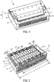
- a battery pack 1 is a power generation and storage device that includes electrochemical cells 2 that are electrically interconnected and stored in an organized manner within a battery pack housing 40.
- the battery housing 40 includes a container 60 and a lid 50 that closes an open end of the container 60.
- the array of cells 2 are electrically connected in series or in parallel to battery pack terminals 54, 55 that protrude from the lid 50.
- the battery pack housing 40 including the lid 50 and container 60 is formed of a non-electrically conductive material.
- the container 60 has passive cooling features as well as features that minimize outer wall stress due to electrochemical cell growth, as discussed in detail below.
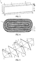
- the cells 2 are lithium-ion cells that include a cell housing 20 that encloses an electrode assembly 4 and an electrolyte to form a power generation and storage unit.
- the electrode assembly 4 includes at least one positive electrode 6, at least one negative electrode 8, a first electrically insulative separator 10 disposed between the positive and negative electrodes 6, 8, and a second electrically insulative separator 12 disposed on the other side of one of the positive electrode 6 and the negative electrode 8.
- the positive and negative electrodes 6, 8 each have a layered structure to facilitate insertion and/or movement of lithium-ions.
- the positive electrode 6 is formed of copper with a graphite coating
- the negative electrode 8 is formed of aluminum with a lithiated metal oxide coating.
- the separators 10, 12 are formed of an electrically insulating material such as a tri-layer polypropylene-polyethylene-polypropylene membrane.
- the electrodes 6, 8 and separators 10, 12 are elongate strips of material that are stacked and then wound about an elliptically shaped mandrel to form an elliptically-shaped or race track-shaped jelly roll assembly 4.
- the term 'strip' refers to a geometry that includes a length l e that is large (e.g., on the order of 1000 x) relative to the height he, and a height he that is large (e.g., on the order of 1000 x) relative to the thickness t e .
- the electrodes 26, 28 may have a thickness t e of 0.03 mm, a height h e of 60 mm and a length l e of 45 m.
- the cell housing 20 has a rectangular prism shape (e.g., prismatic), and includes a first side 22, and a second side 24 opposed to the first side 22, a third side 26 adjoining the first side 22 and the second side24, and a fourth side 28 opposed to the third side 26 and adjoining the first side 22 and the second side 24.
- the first and second sides 22, 24 have the same height as the third and fourth sides 26, 28, but have a larger width.
- the width of the first and second sides 22, 24 is about twice the height, whereas the width of the third and fourth sides 26, 28 is about one-fourth of the height.
- the cell housing 20 includes a first end 30 through which a positive terminal 34 and a negative terminal 36 protrude, and a second end 32 opposed to the first end.
- the electrode assembly 4 is disposed in the cell housing 20 such that the winding axis (e.g., the axis about which the electrodes and separators are wound) 14 extends through the first and second ends 30, 32.
- the electrode assembly 4 experiences dimensional changes during battery charge and discharge. This is due at least in part to expansion of the layered structure of the positive and negative electrodes in the electrode thickness direction due to expansion of the active materials during cycling.
- the expansion of the jelly roll electrode assembly 4 within the cell housing20 results in "cell growth", which corresponds to the outward bowing of the first and second sides 22, 24 of the cell housing 20 in a direction transverse to the winding axis and normal to an outer surface of the first and second sides 22, 24.
- the battery pack housing includes features which accommodate the growth of the cells 2 disposed therein, as discussed further below.
- the array of cells 2 is disposed in the container 60 of the battery pack housing 40.
- the array includes a single row of twelve cells arranged side-by-side such that the second side 24a of one cell 2a faces the first side 22b of the adjacent cell 2b, and such that the first end 30 of each cell faces the lid 50.
- a stacking axis 16 corresponding to the stacking direction of the cell array is transverse to the facing surfaces (e.g., the first and second sides 22, 24) of the cells 2.
- An insulating separator plate 18 is disposed between facing surfaces of adjacent cells 2.
- the array is arranged within the battery pack housing 40 such that the first side 22 of an outermost cell 2 (1) at one end of the array faces and abuts a first inner wall 101 of the container 60, and the second side 24 of an outermost cell 2(12) at the opposed end of the array faces and abuts a second inner wall 121 of the container 60.
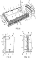
- the container 60 is a box-like structure that includes a base 61, an outer wall 70 that surrounds the base 61 and inner walls 101, 121 disposed between portions of the outer wall 70 and the cells 2.
- the base 61 is rectangular, and has a length dimension that is greater than its width dimension.
- the base 61 includes an inner surface 62 and an outer surface 63 opposed the inner surface 62.
- the outer wall 70 surrounds a peripheral edge of the base 61 and protrudes from the base 61 in a direction that is normal to the base inner surface 62.
- the outer wall 70 forms a rectangular closed section when seen in top plan view, and thus includes four orthogonal outer wall portions.
- the outer wall 70 includes a first portion 71 that extends along the length of the base 61, a second portion 72 adjoining the first portion 71 and extending a long the width of the base 61.
- the outer wall 70 includes a third portion 73 that adjoins the second portion 72 and is opposed to the first portion 71, and a fourth portion 74 that is opposed to the second portion 72 and adjoins the first portion 71 and the third portion 73.
- the first and third portions 71, 73 have a larger area than the second and fourth portions 72, 74, and are parallel to the stacking axis 16 of the cells 2.
- the outer surface 76 of the outer wall 70 includes surface features that enhance cooling of the battery pack.
- the outer surface of the first and third portions 71, 73 includes outwardly protruding cooling ribs 78.
- the cooling ribs 78 extend between the base 61 and a free edge 79 of the outer wall 70, and cover an area that corresponds to the position of the cells 2 disposed within the battery pack 1.
- the first inner wall 101 is disposed inside the outer wall 70, and extends in the width direction. More specifically, the first inner wall 101 is parallel to and spaced apart from both the second portion 72 and the fourth portion 74, and is disposed between a center 64 of the container 60 and the second portion 72 such that a first gap g1 exists between the first inner wall 101 and the second portion 72.
- the first gap g 1 is small relative to an overall length l o of the container 60 as measured between outer surfaces of the second portion 72 and the fourth portion 74, as well as the dimension d of a cell 2 in the stacking direction.
- the first gap g 1 is in a range of 0.5 percent to 2.0 percent of the overall length l o .
- the first gap g 1 is in a range of 5 percent to 30 percent of the dimension d of the cell 2 in the stacking direction.
- the first inner wall 101 includes a pair of parallel, spaced-apart plates 102, 103 that are parallel to the second portion 72 and the fourth portion 74. Angled ribs 106 extend between inner surfaces of the plates 102, 103, resulting in vacancies 107 being formed within the first inner wall 101 that contribute to the ability of the first inner wall 101 to deform under loads applied in a direction normal to the surfaces of the plates 102, 103, such as occurs during cell growth.
- the first inner wall 101 extends between the first portion 71 and the third portion 73.
- the first inner wall 101 abuts and is fixed to each of the first portion 71, the base 61 and the third portion 73.
- the inner wall 101 is formed integrally with outer wall 70 and the base 61. In other embodiments, the inner wall 101 is fixed to the outer wall 70 and the base 61 during manufacture.
- the second inner wall 121 is disposed inside the outer wall 70, and extends in the width direction.
- the second inner wall 121 is parallel to and spaced apart from the second portion 72 and the fourth portion 74.
- the second inner wall 121 is disposed between the center 64 of the container 60 and the fourth portion 74 so as to reside between the first inner wall 101 and the fourth portion 74.
- a second gap g 2 exists between the second inner wall 121 and the fourth portion 74.
- the second gap g 2 is small relative to the overall length l o of the first portion 71, and is larger than the dimension d of a cell 2 in the stacking direction.
- the second gap g 2 is in a range of 10 percent to 20 percent of the overall length l o .
- the second gap g 2 is in a range of 100 percent to 300 percent of the dimension d of the cell 2 in the stacking direction.
- the second inner wall 121 includes a pair of parallel, spaced-apart plates 122, 123 that are parallel to the fourth portion 74.
- Angled structural ribs 126 extend between inner surfaces of the plates 122, 123, resulting in vacancies 127 being formed within the second inner wall 121 that contribute to the ability second inner wall 121 to deform under loads applied in a direction normal to the surfaces of the plates 122, 123, such as occurs during cell growth.
- the second inner wall 121 extends between the first portion 71 and the third portion 73, but is not fixed thereto. Instead, the second inner wall 121 is fixed to the fourth portion 74 via a two pair of arms 132, 142 that extend inward from an inner surface of the fourth portion 74 and serve as a rigid spacer structure that maintains the gap g2 between the second inner wall 121 and the fourth portion 74.
- the first pair of arms 132 is provided along one side edge of the fourth portion 74 so as to be adjacent the first portion 71
- the second pair of arms 142 is provided along the opposed side edge of the fourth portion 74 so as to be adjacent the third portion 73.
- a first catch plate 88 is disposed between the arms 133, 134 of the first pair of arms 132, and a second catch plate 89 is disposed between the arms 143, 144 of the second pair of arms 142.
- the first and second catch plates 88, 89 are parallel to the base 61 and have a catch plate opening 88a, 89a that is disposed between the second inner wall 121 and the fourth portion 74.
- the catch plates 88, 89 are part of a latching structure used to retain the fourth portion 74 in an assembled configuration with the remainder of the outer wall 70, as discussed further below.
- the outer wall 70 is formed as two, separate elements 66, 68 that are configured to detachably engage with each other to form the rectangular closed section described above.
- the first element 66 of the outer wall 70 includes the first, second and third portions 71, 72, 73 that are formed integrally with the base 61 and arranged in a U-shaped configuration when seen in top plan view.
- the second element 68 of the outer wall 70 includes the fourth portion 74, which, when assembled with the first element 66, closes the open end 90 of the U-shaped first element 66 (referred to hereafter as the U open end 90).
- the second element 68, corresponding to fourth portion 74 is formed separately from, and detachably connected to, the first element 66 via the latching structure.
- the latching structure is provided on the inner surface 75 of the outer wall 70, and includes a first pair of eyes 80, 81 that protrude from an inner surface of the first portion 71 at a location adjacent the U open end 90.
- the eyes 80, 81 of the first pair include openings 80a, 81a that are aligned along a first axis 86 that is normal to the base inner surface 62.
- the latching structure includes a second pair of eyes 82, 83 (eye 83 is not visible) that protrude from an inner surface of the third portion 73 at a location adjacent the U open end 90.
- the eyes 82, 83 of the second pair include openings 82a, 83a that are aligned along a second axis 88 that is normal to the base inner surface 62.
- the latching structure also includes the first catch plate 88 that protrudes from the inner surface of the fourth portion 74 at a location adjacent the first portion 71, and the second catch plate 89 that protrudes from an inner surface of the fourth portion 74 at a location adjacent the third portion 73.
- the first catch plate 88 is interposed between the eyes 80, 81 of the first pair such that the first catch plate opening 88a is aligned along the first axis 86 with the openings 80a, 81a of the first pair of eyes.
- the second catch plate 89 is interposed between the eyes 82, 83 of the second pair such that the second catch plate opening 89a is aligned along the second axis 87 with the openings 82a, 83a of the second pair of eyes.
- the latching structure includes a first pin 84 that is aligned with the first axis 86 and passes through the openings 80a, 88a, 81a of the first pair of eyes and the first catch plate 88, and a second pin 85 that is aligned with the second axis 87 and passes through the openings 82a, 89a, 83a of the second pair of eyes and the second catch plate 89.
- the first and second pins 84, 85 cooperate with corresponding eyes and catch plates formed on the outer wall inner surface 75 to detachably connect the first element 66 to the second element 68.
- the lid 50 of the battery pack housing 40 is shaped and dimensioned to close the open end of the container 60.
- a periphery of the container-facing surface 52 of the lid 50 includes openings (not shown) that receive and engage with upright latches 77 provided on the container outer wall 70. The openings and the upright latches cooperate to retain the lid 50 in a closed configuration with respect to the container open end.
- the positive terminal 54 and a negative terminal 55 protrude from an outward-facing surface 51 of the lid 50.
- the battery pack housing 60 is formed of a material that is electrically nonconductive and thermally conductive.
- the battery pack housing 60 may be formed of a molded, high strength plastic with additives that improve thermal conductivity and provide electrical isolation.
- the thermally conductive battery pack housing 60 provides passive cooling of the cells 2 during operation, whereby cell operating efficiency is improved and damage to heat sensitive components of the cell 2 is prevented.
- a seal 56 is provided between a periphery of the container-facing surface 52 of the lid 50 and the free edge 79 of the container outer wall 70.
- the seal may be a gasket or a sealing adhesive or achieved by other conventional techniques.
- the sealing adhesive permits removal of the lid 50 from the container 60, while in other embodiments the sealing adhesive provides a permanent bonding of the lid 50 to the container 60.
- the second element 68 includes the second inner wall 121 that is parallel to and spaced apart from the fourth portion 74 via the two pair of arms 132, 142.
- the gap g 2 between the second inner wall 121 and the fourth portion 74 is used to receive a battery management device 53.
- the battery management device 53 is electrically connected to each cell 2 disposed in the battery pack housing 40, and includes electronics configured to monitor and control function of the electrochemical cells. For example, the battery management device 53 may regulate the battery pack 1 by actively influencing the electric current flow.
- the electronics may include a printed circuit board, a resistance busbar, a relay, a fuse, etc..
- the battery management device 53 is incorporated into the lid structure, and protrudes from the lid container-facing surface 52 and into the vacancy between the second inner wall 121 and the fourth portion of the outer wall 70. In other embodiments, the battery management device 53 is provided separately from the lid 50, and is disposed within the vacancy between the second inner wall 121 and the fourth portion of the outer wall 70.
- the battery pack 1 is assembled as follows.
- the first element 66 is separated from the second element 68, and cells 2 are placed within the first element 66 while the second element 68 is disengaged from the first element 66.
- the cells 2 are arranged side-by-side in a 1 x (number of cells) array with the electrically-insulating separator plates 18 disposed in between adjacent cells 2.
- the number of cells 2 placed within the battery pack 1 and the dimensions of cells 2 are set so that the overall length of the cell array in the stacking direction is greater than the distance d2 between facing surfaces of the first and second inner walls 101, 121.
- the second element 68 is partially assembled with the first element 66 with the second inner wall 121 abutting the outermost cell 2(12) of the cell array.
- the fourth portion 74 does not abut the first and third portions 71, 73 due to the overall length of the cell array.
- the second element 68 including the second inner wall 121 is then pushed toward the first inner wall 101 until the fourth portion 74 abuts the first and third portions 71, 73.
- the openings 80a, 81a, 82a, 83a, 88a, 89a of the latching structure are aligned along the corresponding axes 86, 87.
- a second seal (not shown) may be provided between abutting surfaces of the first element 66 and the second element 68. This method of assembly is achievable since the second element 68 including the second inner wall 121 is movable relative to the first element 66 including the first portion 71, the base 61 and the third portion 73.
- movable refers to movement of the second inner wall 121 as a unit relative to the first and third portions 71, 73, and is considered to be different than the terms “deformation” and “deflection” which are used to refer to changes in the shape of the first and second inner walls 101, 121.
- an alternative embodiment container 260 may be used with the lid 50 to form a battery pack.
- the container 260 is similar to the container 60 described above with respect to Figs. 1-10 , and common elements will be referred to using common reference numbers.
- the container 260 is a box-like structure that includes the base 61, an outer wall 270 that surrounds the base 61 and inner walls 101, 221 disposed between portions of the outer wall 270 and the cells 2.
- the outer wall 270 and the second inner wall 221 of the container 260 differ from the previously-described outer wall 70 and second inner wall 121, as now described.
- the outer wall 270 and the base 61 are a unitary structure that includes four orthogonal outer wall portions 271, 272, 273, 274 that together surround a peripheral edge of the base 61 and protrude from the base 61 in a direction that is normal to the base inner surface 62.
- the outer wall portions 271, 272, 273, 274 are formed integrally (e.g., as a monolithic structure) with each other and the base 61 for example using a molding process.
- the outer wall portions 271, 272, 273, 274 are fixed to each other and the base 61 during manufacture.
- the second inner wall 221 is disposed inside the outer wall 270, and extends in the width direction.
- the second inner wall 221 is parallel to and spaced apart from the second portion 272 and the fourth portion 274.
- the second inner wall 221 is disposed between the first inner wall 101 and the fourth portion 274.
- the second inner wall 221 includes the pair of parallel, spaced-apart plates 122, 123 that are parallel to the fourth portion 274. Angled structural ribs 126 extend between inner surfaces of the plates 122, 123, resulting in vacancies 127 being formed within the second inner wall 221 that contribute to the ability of the second inner wall 221 to deform under loads applied in a direction normal to the surfaces of the plates 122, 123, such as occurs during cell growth.
- the second inner wall 221 extends between the first portion 271 and the third portion 273, but is not fixed to the outer wall 270 or the base 61. As a result, the second inner wall 221 is movable relative to the outer wall 170 such that a spacing of the second inner wall 221 from both the first inner wall 101 and the fourth portion 274 can be changed.
- the second inner wall 221 is free-floating with respect to the outer wall 270 and the base 61. Since the second inner wall 221 is free-floating, assembly of the cells 2 within the container 260 under a compression load in the stacking direction can be accomplished while providing a unitary, four-sided outer wall structure.
- the unitary, four-sided outer wall structure is dimensionally stable due to its unitary structure in combination with use of the inner walls 101, 221, and thus can be reliably sealed.
- the second inner wall 221 is disposed between the array of cells 2 and the fourth portion 274 such that the second gap g 2 exists between the second inner wall 221 and the fourth portion 274.
- the gap g 2 is achieved by providing first and second spacers 232, 242 between the second inner wall 221 and the fourth portion 274.
- the first spacer 232 is provided along one side edge of the fourth portion 274 so as to be adjacent the first portion 271
- the second spacer 242 is provided along the opposed side edge of the fourth portion 274 so as to be adjacent the third portion 273.
- the first and second spacers 232, 242 are rectangular tubes that are dimensioned to provide the desired gap g 2 .
- the first and second spacers 232, 242 are tapered along an axis that is normal to the base inner surface 62, whereby the first and second spacers 232, 242 are used drive the second inner wall 221 and the cell array toward the first inner wall 101 during assembly, and thus apply a compressive force to the cell array in the stacking direction.
- the first and second spacers 232, 242 maintain the gap g 2 between the second inner wall 221 and the fourth portion 274 upon assembly.
- FIG. 13 another alternative embodiment container 360 may be used with the lid 50 to form a battery pack.
- the container 360 is similar to the container 260 described above with respect to Figs. 11-12 , and common elements will be referred to using common reference numbers.
- the container 360 is a box-like structure that includes the base 61, an outer wall 270 that surrounds the base 61 and inner walls 101, 321 disposed between portions of the outer wall 270 and the cells 2.
- the second inner wall 321 of the container 360 differs from the second inner wall 221 of Figs. 11-12 as described in detail below.
- the outer wall 270 and the base 61 are a unitary structure that includes four orthogonal outer wall portions 271, 272, 273, 274 that together surround a peripheral edge of the base 61 and protrude from the base 61 in a direction that is normal to the base inner surface 62.
- the outer wall portions 271, 272, 273, 274 are formed integrally (e.g., as a monolithic structure) with each other and the base 61 for example using a molding process.
- the outer wall portions 271, 272, 273, 274 are fixed to each other and the base 61 during manufacture.
- the second inner wall 321 is disposed inside the outer wall 270, and extends in the width direction.
- the second inner wall 321 is parallel to and spaced apart from the second portion 272 and the fourth portion 274.
- the second inner wall 321 is disposed between the first inner wall 101 and the fourth portion 274.
- the second inner wall 321 is formed having an open cell structure including angled structural ribs 326 that extend in a direction perpendicular to the second inner wall inner face 322, in parallel to the first and third outer wall portions 271, 273, and define rectangular open cells or vacancies 327.
- the vacancies 327 formed within the second inner wall 321 contribute to the ability of the second inner wall 321 to deform under loads applied in a direction normal to the second inner wall 321, such as occurs during cell growth.
- the second inner wall inner face 322 is parallel to the second and fourth portions 272, 274, the opposed second inner wall outer face 323 may not be parallel to the second and fourth portions 272, 274 in order to provide a wall geometry in which wall strength is optimized.
- the illustrated embodiment shows one possible second inner wall 321 configuration, in which the outer face 323 is curved as seen in a top plan view of the container 360.
- the second inner wall outer face 323 is convex so as to protrude toward the second portion, whereby a center portion of the second inner wall 321 has a greater thickness than portions of the second inner wall 321 adjacent the first and third portions 271, 273.
- the second inner wall 321 extends between the first portion 271 and the third portion 273, but is not fixed to the outer wall 270 or the base 61. As a result, the second inner wall 321 is movable relative to the outer wall 270 such that a spacing of the second inner wall 321 from both the first inner wall 101 and the fourth portion 274 can be changed.
- the second inner wall 321 is free-floating with respect to the outer wall 270 and the base 61. Since the second inner wall 321 is free-floating, assembly of the cells 2 within the container 260 under a compression load in the stacking direction can be accomplished while providing a unitary, four-sided outer wall structure.
- the unitary, four-sided outer wall structure is dimensionally stable due to its unitary structure in combination with use of the inner walls 101, 321, and thus can be reliably sealed.
- the second inner wall 321 is disposed between the array of cells 2 and the fourth portion 274 such that the second gap g 2 exists between the second inner wall 321 and the fourth portion 274.
- the gap g 2 is achieved by providing first and second spacers 332, 342 between the second inner wall 321 and the fourth portion 274.
- the first spacer 332 is provided along one side edge of the fourth portion 274 so as to be adjacent the first portion 271
- the second spacer 342 is provided along the opposed side edge of the fourth portion 274 so as to be adjacent the third portion 273.
- the first and second spacers 332, 342 are rigid elements that are dimensioned to provide the desired gap g 2 , and are shaped to correspond to, and cooperate with, the shape of the second inner wall outer face 323.
- the shape of the first and second spacers 332, 342 is optimized together with the shape of the second inner wall 321 to provide optimal strength of the second inner wall 321.
- the first and second spacers 332, 342 may be tapered along an axis that is normal to the base inner surface 62, whereby the first and second spacers 332, 342 are used drive the second inner wall 321 and the cell array toward the first inner wall 101 during assembly, and thus apply a compressive force to the cell array in the stacking direction.
- the first and second spacers 332, 342 maintain the gap g 2 between the second inner wall 321 and the fourth portion 274 upon assembly.
- the containers 60, 260, 360 described herein each include a fixed first inner wall 101 that is separated from the outer wall 70, 270 via a first gap g 1 , it is contemplated that the gap g1 may be eliminated in some embodiments, whereby the inner wall 101 would become the second portion 72, 272 of the outer wall 70, 720, and would have properties that would permit some deformation of the inward facing surface 122 thereof.
- the electrode assembly 4 is not limited to this electrode configuration.
- the electrode assembly 4 may include a stacked or folded arrangement of electrode plates, or other suitable electrode arrangement.
- the cells 2 are described as being lithium ion cells, the cells 2 are not limited to this type of cell.
- the cells 2 may include different combinations of electrode materials and electrolytes, including lead-acid, nickel cadmium (NiCd), nickel metal hydride (NiMH), and lithium ion polymer.
- the battery pack 1 is not limited to having twelve cells 2.
- the number of cells used may be greater or fewer than twelve, and is determined by the requirements of the specific application.
Landscapes
- Chemical & Material Sciences (AREA)
- Chemical Kinetics & Catalysis (AREA)
- Electrochemistry (AREA)
- General Chemical & Material Sciences (AREA)
- Engineering & Computer Science (AREA)
- Manufacturing & Machinery (AREA)
- Microelectronics & Electronic Packaging (AREA)
- Aviation & Aerospace Engineering (AREA)
- Battery Mounting, Suspending (AREA)
- Secondary Cells (AREA)
- Connection Of Batteries Or Terminals (AREA)
Description
- The present invention relates to a battery pack for storage of electrochemical cells, including a battery pack housing having passive cooling features as well as features that minimize outer wall stress due to electrochemical cell growth.
- Battery packs provide power for various technologies ranging from portable electronics to renewable power systems and environmentally friendly vehicles. For example, hybrid electric vehicles (HEV) use a battery pack and an electric motor in conjunction with a combustion engine to increase fuel efficiency. Battery packs are formed of a plurality of battery modules, where each battery module includes several electrochemical cells. The cells are arranged in stacks and are electrically connected in series or in parallel. Likewise, the battery modules within a battery pack are electrically connected in series or in parallel.
- Some battery packs used with conventional hybrid electric vehicles are designed to provide a relatively high voltage, for example 400 volts (V). To achieve the high voltage, battery packs are relatively large and include hundreds of electrochemical cells. Moreover, to accommodate the high voltage, the components in the electrical system are relatively expensive and subject to high voltage protection requirements. It is desirable to form a battery pack which has fewer and less expensive components.
-
US 2015/280193 A1 describes an energy storage apparatus including one or more energy storage devices, an outer covering arranged outside the one or more energy storage devices, a partition member arranged on a side of any one of the one or more energy storage devices, and a supporter which supports the partition member at a predetermined position. -
US 2015/069829 A1 describes a battery module for use in a vehicle, wherein the battery module includes a housing, a plurality of battery cells disposed within the housing, and solid state pre-charge control circuitry that pre-charges a direct current (DC) bus coupled between the battery module and an electronic component of the vehicle. -
JP 2005 339925 A -
US 2015/214570 A1 describes a battery cell for pre-stressed battery modules, wherein the battery cell has a cell housing and a chemicals carrier which is arranged in the cell housing having a bulging design. -
US 2013/288096 A1 describes systems for providing assemblies for containing multi-cell battery systems, and/or multi-cell batteries using such enclosures, wherein a battery case is partitioned into a battery management portion and a cell portion, configured to accept corresponding battery components in a modular fashion. -
US 2013/130087 A1 describes a non-aqueous electrolyte battery module including a plurality of non-aqueous electrolyte batteries, a plurality of heat dissipating members, a plurality of heat insulating members, and an exterior casing housing the non-aqueous electrolyte batteries, the heat dissipating members and the heat insulating members.
JP 2014 175078 A
JP 2009 238606 A - The invention claims a battery pack housing according to
claim 1. -
-
Fig. 1 is top perspective view of a battery pack. -
Fig. 2 is a top perspective view of the battery pack ofFig. 1 with the lid omitted. -
Fig. 3 is a schematic view of the arrangement of electrode and separator strips used to form the electrode assembly of each cell. -
Fig. 4 is a cross-sectional view of the electrode assembly as seen in a direction transverse to the electrode winding axis. -
Fig. 5 is a perspective exploded view of a portion of the cell array illustrating the alternating arrangement between cells and insulative separator plates within the cell array. -
Fig. 6 is a top perspective exploded view of the container of the battery pack housing. -
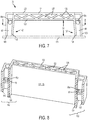
Fig. 7 is a top plan view of the second element of the container. -
Fig. 8 is a cross-sectional view of the container as seen alongline 8—8 ofFig. 7 . -
Fig. 9 is a cross-sectional view of the container as seen alongline 9—9 ofFig. 10 . -
Fig. 10 is a top plan view of one end of the container ofFig. 6 illustrating a battery management device disposed in the container. -
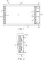
Fig. 11 is a top plan view of an alternative embodiment container. -
Fig. 12 is a top plan view of one end of the container ofFig. 11 illustrating a battery management device disposed in the container. -
Fig. 13 is a perspective view of another alternative embodiment container. - Referring to
Figs. 1-2 , abattery pack 1 is a power generation and storage device that includeselectrochemical cells 2 that are electrically interconnected and stored in an organized manner within abattery pack housing 40. Thebattery housing 40 includes acontainer 60 and alid 50 that closes an open end of thecontainer 60. Within the battery pack housing 40, the array ofcells 2 are electrically connected in series or in parallel tobattery pack terminals lid 50. Thebattery pack housing 40 including thelid 50 andcontainer 60 is formed of a non-electrically conductive material. In addition, thecontainer 60 has passive cooling features as well as features that minimize outer wall stress due to electrochemical cell growth, as discussed in detail below. - Referring to
Figs. 3-5 , thecells 2 are lithium-ion cells that include acell housing 20 that encloses an electrode assembly 4 and an electrolyte to form a power generation and storage unit. The electrode assembly 4 includes at least onepositive electrode 6, at least onenegative electrode 8, a first electricallyinsulative separator 10 disposed between the positive andnegative electrodes insulative separator 12 disposed on the other side of one of thepositive electrode 6 and thenegative electrode 8. - The positive and
negative electrodes positive electrode 6 is formed of copper with a graphite coating, and thenegative electrode 8 is formed of aluminum with a lithiated metal oxide coating. Theseparators - The
electrodes separators electrodes - The
cell housing 20 has a rectangular prism shape (e.g., prismatic), and includes afirst side 22, and asecond side 24 opposed to thefirst side 22, athird side 26 adjoining thefirst side 22 and the second side24, and afourth side 28 opposed to thethird side 26 and adjoining thefirst side 22 and thesecond side 24. The first andsecond sides fourth sides second sides fourth sides cell housing 20 includes afirst end 30 through which apositive terminal 34 and anegative terminal 36 protrude, and asecond end 32 opposed to the first end. The electrode assembly 4 is disposed in thecell housing 20 such that the winding axis (e.g., the axis about which the electrodes and separators are wound) 14 extends through the first andsecond ends - The electrode assembly 4 experiences dimensional changes during battery charge and discharge. This is due at least in part to expansion of the layered structure of the positive and negative electrodes in the electrode thickness direction due to expansion of the active materials during cycling. The expansion of the jelly roll electrode assembly 4 within the cell housing20 results in "cell growth", which corresponds to the outward bowing of the first and
second sides cell housing 20 in a direction transverse to the winding axis and normal to an outer surface of the first andsecond sides cells 2 disposed therein, as discussed further below. - Referring to
Figs. 2 and5 , the array ofcells 2 is disposed in thecontainer 60 of thebattery pack housing 40. For example, in the illustrated embodiment, the array includes a single row of twelve cells arranged side-by-side such that thesecond side 24a of onecell 2a faces thefirst side 22b of theadjacent cell 2b, and such that thefirst end 30 of each cell faces thelid 50. Astacking axis 16 corresponding to the stacking direction of the cell array is transverse to the facing surfaces (e.g., the first andsecond sides 22, 24) of thecells 2. Aninsulating separator plate 18 is disposed between facing surfaces ofadjacent cells 2. The array is arranged within thebattery pack housing 40 such that thefirst side 22 of an outermost cell 2 (1) at one end of the array faces and abuts a firstinner wall 101 of thecontainer 60, and thesecond side 24 of an outermost cell 2(12) at the opposed end of the array faces and abuts a secondinner wall 121 of thecontainer 60. - Referring to
Figs. 2 and6 , thecontainer 60 is a box-like structure that includes abase 61, anouter wall 70 that surrounds thebase 61 andinner walls outer wall 70 and thecells 2. Thebase 61 is rectangular, and has a length dimension that is greater than its width dimension. Thebase 61 includes aninner surface 62 and anouter surface 63 opposed theinner surface 62. Theouter wall 70 surrounds a peripheral edge of thebase 61 and protrudes from the base 61 in a direction that is normal to the baseinner surface 62. - The
outer wall 70 forms a rectangular closed section when seen in top plan view, and thus includes four orthogonal outer wall portions. In particular, theouter wall 70 includes afirst portion 71 that extends along the length of thebase 61, asecond portion 72 adjoining thefirst portion 71 and extending a long the width of thebase 61. Theouter wall 70 includes athird portion 73 that adjoins thesecond portion 72 and is opposed to thefirst portion 71, and afourth portion 74 that is opposed to thesecond portion 72 and adjoins thefirst portion 71 and thethird portion 73. The first andthird portions fourth portions axis 16 of thecells 2. The outer surface 76 of theouter wall 70 includes surface features that enhance cooling of the battery pack. In particular, the outer surface of the first andthird portions ribs 78. The coolingribs 78 extend between the base 61 and afree edge 79 of theouter wall 70, and cover an area that corresponds to the position of thecells 2 disposed within thebattery pack 1. - The first
inner wall 101 is disposed inside theouter wall 70, and extends in the width direction. More specifically, the firstinner wall 101 is parallel to and spaced apart from both thesecond portion 72 and thefourth portion 74, and is disposed between acenter 64 of thecontainer 60 and thesecond portion 72 such that a first gap g1 exists between the firstinner wall 101 and thesecond portion 72. The first gap g1 is small relative to an overall length ℓo of thecontainer 60 as measured between outer surfaces of thesecond portion 72 and thefourth portion 74, as well as the dimension d of acell 2 in the stacking direction. For example, in some embodiments, the first gap g1 is in a range of 0.5 percent to 2.0 percent of the overall length ℓo. Similarly, in some embodiments, the first gap g1 is in a range of 5 percent to 30 percent of the dimension d of thecell 2 in the stacking direction. - The first
inner wall 101 includes a pair of parallel, spaced-apartplates second portion 72 and thefourth portion 74.Angled ribs 106 extend between inner surfaces of theplates vacancies 107 being formed within the firstinner wall 101 that contribute to the ability of the firstinner wall 101 to deform under loads applied in a direction normal to the surfaces of theplates - The first
inner wall 101 extends between thefirst portion 71 and thethird portion 73. In particular, the firstinner wall 101 abuts and is fixed to each of thefirst portion 71, thebase 61 and thethird portion 73. For example, in some embodiments, theinner wall 101 is formed integrally withouter wall 70 and thebase 61. In other embodiments, theinner wall 101 is fixed to theouter wall 70 and the base 61 during manufacture. - The second
inner wall 121 is disposed inside theouter wall 70, and extends in the width direction. The secondinner wall 121 is parallel to and spaced apart from thesecond portion 72 and thefourth portion 74. In addition, the secondinner wall 121 is disposed between thecenter 64 of thecontainer 60 and thefourth portion 74 so as to reside between the firstinner wall 101 and thefourth portion 74. A second gap g2 exists between the secondinner wall 121 and thefourth portion 74. The second gap g2 is small relative to the overall length ℓo of thefirst portion 71, and is larger than the dimension d of acell 2 in the stacking direction. For example, in some embodiments, the second gap g2 is in a range of 10 percent to 20 percent of the overall length ℓo. However, in some embodiments, the second gap g2 is in a range of 100 percent to 300 percent of the dimension d of thecell 2 in the stacking direction. - Like the first
inner wall 101, the secondinner wall 121 includes a pair of parallel, spaced-apartplates fourth portion 74. Angledstructural ribs 126 extend between inner surfaces of theplates vacancies 127 being formed within the secondinner wall 121 that contribute to the ability secondinner wall 121 to deform under loads applied in a direction normal to the surfaces of theplates - Referring to
Figs. 6-8 (battery pack housing not part of the invention as claimed), the secondinner wall 121 extends between thefirst portion 71 and thethird portion 73, but is not fixed thereto. Instead, the secondinner wall 121 is fixed to thefourth portion 74 via a two pair ofarms fourth portion 74 and serve as a rigid spacer structure that maintains the gap g2 between the secondinner wall 121 and thefourth portion 74. The first pair ofarms 132 is provided along one side edge of thefourth portion 74 so as to be adjacent thefirst portion 71, and the second pair ofarms 142 is provided along the opposed side edge of thefourth portion 74 so as to be adjacent thethird portion 73. Afirst catch plate 88 is disposed between thearms arms 132, and asecond catch plate 89 is disposed between thearms arms 142. The first andsecond catch plates base 61 and have a catch plate opening 88a, 89a that is disposed between the secondinner wall 121 and thefourth portion 74. Thecatch plates fourth portion 74 in an assembled configuration with the remainder of theouter wall 70, as discussed further below. - In the embodiment illustrated in
Figs. 1-8 , theouter wall 70 is formed as two,separate elements first element 66 of theouter wall 70 includes the first, second andthird portions base 61 and arranged in a U-shaped configuration when seen in top plan view. Thesecond element 68 of theouter wall 70 includes thefourth portion 74, which, when assembled with thefirst element 66, closes theopen end 90 of the U-shaped first element 66 (referred to hereafter as the U open end 90). Thesecond element 68, corresponding tofourth portion 74, is formed separately from, and detachably connected to, thefirst element 66 via the latching structure. - The latching structure is provided on the
inner surface 75 of theouter wall 70, and includes a first pair ofeyes first portion 71 at a location adjacent the Uopen end 90. Theeyes openings first axis 86 that is normal to the baseinner surface 62. The latching structure includes a second pair ofeyes 82, 83 (eye 83 is not visible) that protrude from an inner surface of thethird portion 73 at a location adjacent the Uopen end 90. Theeyes 82, 83 of the second pair includeopenings 82a, 83a that are aligned along asecond axis 88 that is normal to the baseinner surface 62. The latching structure also includes thefirst catch plate 88 that protrudes from the inner surface of thefourth portion 74 at a location adjacent thefirst portion 71, and thesecond catch plate 89 that protrudes from an inner surface of thefourth portion 74 at a location adjacent thethird portion 73. When thesecond element 68, orfourth portion 74, is assembled with thefirst element 66, thefirst catch plate 88 is interposed between theeyes catch plate opening 88a is aligned along thefirst axis 86 with theopenings second catch plate 89 is interposed between theeyes 82, 83 of the second pair such that the secondcatch plate opening 89a is aligned along thesecond axis 87 with theopenings 82a, 83a of the second pair of eyes. The latching structure includes afirst pin 84 that is aligned with thefirst axis 86 and passes through theopenings first catch plate 88, and asecond pin 85 that is aligned with thesecond axis 87 and passes through theopenings second catch plate 89. In particular, the first andsecond pins inner surface 75 to detachably connect thefirst element 66 to thesecond element 68. - Referring to
Figs. 1 and9 , thelid 50 of thebattery pack housing 40 is shaped and dimensioned to close the open end of thecontainer 60. A periphery of the container-facingsurface 52 of thelid 50 includes openings (not shown) that receive and engage with upright latches 77 provided on the containerouter wall 70. The openings and the upright latches cooperate to retain thelid 50 in a closed configuration with respect to the container open end. Thepositive terminal 54 and anegative terminal 55 protrude from an outward-facingsurface 51 of thelid 50. - The
battery pack housing 60 is formed of a material that is electrically nonconductive and thermally conductive. For example, thebattery pack housing 60 may be formed of a molded, high strength plastic with additives that improve thermal conductivity and provide electrical isolation. When used in conjunction with the coolingribs 78, the thermally conductivebattery pack housing 60 provides passive cooling of thecells 2 during operation, whereby cell operating efficiency is improved and damage to heat sensitive components of thecell 2 is prevented. - A
seal 56 is provided between a periphery of the container-facingsurface 52 of thelid 50 and thefree edge 79 of the containerouter wall 70. The seal may be a gasket or a sealing adhesive or achieved by other conventional techniques. In some embodiments where a sealing adhesive is used, the sealing adhesive permits removal of thelid 50 from thecontainer 60, while in other embodiments the sealing adhesive provides a permanent bonding of thelid 50 to thecontainer 60. - Referring to
Figs. 6 ,7 and10 (battery pack housing not part of the invention as claimed), thesecond element 68 includes the secondinner wall 121 that is parallel to and spaced apart from thefourth portion 74 via the two pair ofarms inner wall 121 and thefourth portion 74 is used to receive abattery management device 53. Thebattery management device 53 is electrically connected to eachcell 2 disposed in thebattery pack housing 40, and includes electronics configured to monitor and control function of the electrochemical cells. For example, thebattery management device 53 may regulate thebattery pack 1 by actively influencing the electric current flow. The electronics may include a printed circuit board, a resistance busbar, a relay, a fuse, etc.. In some embodiments, thebattery management device 53 is incorporated into the lid structure, and protrudes from the lid container-facingsurface 52 and into the vacancy between the secondinner wall 121 and the fourth portion of theouter wall 70. In other embodiments, thebattery management device 53 is provided separately from thelid 50, and is disposed within the vacancy between the secondinner wall 121 and the fourth portion of theouter wall 70. - The
battery pack 1 is assembled as follows. Thefirst element 66 is separated from thesecond element 68, andcells 2 are placed within thefirst element 66 while thesecond element 68 is disengaged from thefirst element 66. Thecells 2 are arranged side-by-side in a 1 x (number of cells) array with the electrically-insulatingseparator plates 18 disposed in betweenadjacent cells 2. The number ofcells 2 placed within thebattery pack 1 and the dimensions ofcells 2 are set so that the overall length of the cell array in the stacking direction is greater than the distance d2 between facing surfaces of the first and secondinner walls second element 68 is partially assembled with thefirst element 66 with the secondinner wall 121 abutting the outermost cell 2(12) of the cell array. In this initial position, thefourth portion 74 does not abut the first andthird portions second element 68 including the secondinner wall 121 is then pushed toward the firstinner wall 101 until thefourth portion 74 abuts the first andthird portions openings axes pins second element 68 is secured to thefirst element 66 and the container is complete, and whereby thecells 2 are disposed within thecontainer 60 under compression in the direction of the stackingaxis 16. In some embodiments, a second seal (not shown) may be provided between abutting surfaces of thefirst element 66 and thesecond element 68. This method of assembly is achievable since thesecond element 68 including the secondinner wall 121 is movable relative to thefirst element 66 including thefirst portion 71, thebase 61 and thethird portion 73. As used herein, the term "movable" refers to movement of the secondinner wall 121 as a unit relative to the first andthird portions inner walls - Referring to
Figs. 11-12 , analternative embodiment container 260 may be used with thelid 50 to form a battery pack. Thecontainer 260 is similar to thecontainer 60 described above with respect toFigs. 1-10 , and common elements will be referred to using common reference numbers. Thecontainer 260 is a box-like structure that includes thebase 61, an outer wall 270 that surrounds thebase 61 andinner walls cells 2. The outer wall 270 and the secondinner wall 221 of thecontainer 260 differ from the previously-describedouter wall 70 and secondinner wall 121, as now described. - In the
container 260, the outer wall 270 and the base 61 are a unitary structure that includes four orthogonalouter wall portions base 61 and protrude from the base 61 in a direction that is normal to the baseinner surface 62. In some embodiments, theouter wall portions base 61 for example using a molding process. In other embodiments, theouter wall portions - As in the previously-described embodiment, the second
inner wall 221 is disposed inside the outer wall 270, and extends in the width direction. The secondinner wall 221 is parallel to and spaced apart from thesecond portion 272 and thefourth portion 274. In addition, the secondinner wall 221 is disposed between the firstinner wall 101 and thefourth portion 274. - The second
inner wall 221 includes the pair of parallel, spaced-apartplates fourth portion 274. Angledstructural ribs 126 extend between inner surfaces of theplates vacancies 127 being formed within the secondinner wall 221 that contribute to the ability of the secondinner wall 221 to deform under loads applied in a direction normal to the surfaces of theplates - The second
inner wall 221 extends between thefirst portion 271 and thethird portion 273, but is not fixed to the outer wall 270 or thebase 61. As a result, the secondinner wall 221 is movable relative to the outer wall 170 such that a spacing of the secondinner wall 221 from both the firstinner wall 101 and thefourth portion 274 can be changed. The secondinner wall 221 is free-floating with respect to the outer wall 270 and thebase 61. Since the secondinner wall 221 is free-floating, assembly of thecells 2 within thecontainer 260 under a compression load in the stacking direction can be accomplished while providing a unitary, four-sided outer wall structure. The unitary, four-sided outer wall structure is dimensionally stable due to its unitary structure in combination with use of theinner walls - When the battery pack 100 is assembled, the second
inner wall 221 is disposed between the array ofcells 2 and thefourth portion 274 such that the second gap g2 exists between the secondinner wall 221 and thefourth portion 274. The gap g2 is achieved by providing first andsecond spacers inner wall 221 and thefourth portion 274. Thefirst spacer 232 is provided along one side edge of thefourth portion 274 so as to be adjacent thefirst portion 271, and thesecond spacer 242 is provided along the opposed side edge of thefourth portion 274 so as to be adjacent thethird portion 273. In the illustrated embodiment, the first andsecond spacers second spacers inner surface 62, whereby the first andsecond spacers inner wall 221 and the cell array toward the firstinner wall 101 during assembly, and thus apply a compressive force to the cell array in the stacking direction. In addition, the first andsecond spacers inner wall 221 and thefourth portion 274 upon assembly. - Referring to
Fig. 13 , anotheralternative embodiment container 360 may be used with thelid 50 to form a battery pack. Thecontainer 360 is similar to thecontainer 260 described above with respect toFigs. 11-12 , and common elements will be referred to using common reference numbers. Thecontainer 360 is a box-like structure that includes thebase 61, an outer wall 270 that surrounds thebase 61 andinner walls cells 2. The secondinner wall 321 of thecontainer 360 differs from the secondinner wall 221 ofFigs. 11-12 as described in detail below. - In the
container 360, the outer wall 270 and the base 61 are a unitary structure that includes four orthogonalouter wall portions base 61 and protrude from the base 61 in a direction that is normal to the baseinner surface 62. In some embodiments, theouter wall portions base 61 for example using a molding process. In other embodiments, theouter wall portions - As in the previously-described embodiment, the second
inner wall 321 is disposed inside the outer wall 270, and extends in the width direction. The secondinner wall 321 is parallel to and spaced apart from thesecond portion 272 and thefourth portion 274. In addition, the secondinner wall 321 is disposed between the firstinner wall 101 and thefourth portion 274. - The second
inner wall 321 is formed having an open cell structure including angled structural ribs 326 that extend in a direction perpendicular to the second inner wallinner face 322, in parallel to the first and thirdouter wall portions vacancies 327. Thevacancies 327 formed within the secondinner wall 321 contribute to the ability of the secondinner wall 321 to deform under loads applied in a direction normal to the secondinner wall 321, such as occurs during cell growth. Although the second inner wallinner face 322 is parallel to the second andfourth portions outer face 323 may not be parallel to the second andfourth portions inner wall 321 configuration, in which theouter face 323 is curved as seen in a top plan view of thecontainer 360. In this example, the second inner wallouter face 323 is convex so as to protrude toward the second portion, whereby a center portion of the secondinner wall 321 has a greater thickness than portions of the secondinner wall 321 adjacent the first andthird portions - The second
inner wall 321 extends between thefirst portion 271 and thethird portion 273, but is not fixed to the outer wall 270 or thebase 61. As a result, the secondinner wall 321 is movable relative to the outer wall 270 such that a spacing of the secondinner wall 321 from both the firstinner wall 101 and thefourth portion 274 can be changed. The secondinner wall 321 is free-floating with respect to the outer wall 270 and thebase 61. Since the secondinner wall 321 is free-floating, assembly of thecells 2 within thecontainer 260 under a compression load in the stacking direction can be accomplished while providing a unitary, four-sided outer wall structure. The unitary, four-sided outer wall structure is dimensionally stable due to its unitary structure in combination with use of theinner walls - When the battery pack 100 is assembled, the second
inner wall 321 is disposed between the array ofcells 2 and thefourth portion 274 such that the second gap g2 exists between the secondinner wall 321 and thefourth portion 274. The gap g2 is achieved by providing first andsecond spacers inner wall 321 and thefourth portion 274. Thefirst spacer 332 is provided along one side edge of thefourth portion 274 so as to be adjacent thefirst portion 271, and thesecond spacer 342 is provided along the opposed side edge of thefourth portion 274 so as to be adjacent thethird portion 273. In the illustrated embodiment, the first andsecond spacers outer face 323. In particular, the shape of the first andsecond spacers inner wall 321 to provide optimal strength of the secondinner wall 321. In some embodiments, the first andsecond spacers inner surface 62, whereby the first andsecond spacers inner wall 321 and the cell array toward the firstinner wall 101 during assembly, and thus apply a compressive force to the cell array in the stacking direction. In addition, the first andsecond spacers inner wall 321 and thefourth portion 274 upon assembly. - Although the
containers inner wall 101 that is separated from theouter wall 70, 270 via a first gap g1, it is contemplated that the gap g1 may be eliminated in some embodiments, whereby theinner wall 101 would become thesecond portion outer wall 70, 720, and would have properties that would permit some deformation of the inward facingsurface 122 thereof. - Although the
cells 2 are described as housing the electrode assembly 4 having a jelly roll electrode configuration, the electrode assembly 4 is not limited to this electrode configuration. For example, the electrode assembly 4 may include a stacked or folded arrangement of electrode plates, or other suitable electrode arrangement. - Although the
cells 2 are described as being lithium ion cells, thecells 2 are not limited to this type of cell. For example, thecells 2 may include different combinations of electrode materials and electrolytes, including lead-acid, nickel cadmium (NiCd), nickel metal hydride (NiMH), and lithium ion polymer. - Although the illustrated embodiment includes twelve
cells 2 in the cell array, thebattery pack 1 is not limited to having twelvecells 2. The number of cells used may be greater or fewer than twelve, and is determined by the requirements of the specific application. - Selective illustrative embodiments of the battery pack and battery pack housing are described above in some detail. It should be understood that only structures considered necessary for clarifying these devices have been described herein. Other conventional structures, and those of ancillary and auxiliary components of the battery pack system, are assumed to be known and understood by those skilled in the art. Moreover, while working examples of the battery pack and battery pack housing been described above, the battery pack and/or battery pack housing is not limited to the working examples described above, but various design alterations may be carried out without departing from the devices as set forth in the claims.
Claims (14)
- A battery pack housing (40) configured to receive a plurality of electrochemical cells (2), the battery pack housing (40) comprising a container (60, 260, 360) that includesa base (61) that includes an inner surface (62), an outer surface (63) opposed to the inner surface (62), and a peripheral edge that joins the inner surface (62) to the outer surface (63),an outer wall (70, 270) that surrounds the peripheral edge and protrudes from the base (61) in a direction that is normal to the inner surface (62) of the base (61), the outer wall (70, 270) including a first portion (71, 271), a second portion (72, 272) adjoining the first portion (71, 271), a third portion (73, 273) adjoining the second portion (72, 272) and opposed to the first portion (71, 271), and a fourth portion (74, 274) opposed to the second portion (72, 272),a first inner wall (101) that extends between the first portion (71, 271) and the third portion (73, 273), the first inner wall (101) being fixed to each of the first portion (71, 271) and the third portion (73, 273), anda second inner wall (121, 221, 321) that extends between the first portion (71, 271) and the third portion (73, 273), is disposed between the first inner wall (101) and the fourth portion (74, 274), the second inner wall (121, 221, 321) being free-floating relative to the outer wall (70, 270) in a stacking direction of the cells (2) such that a spacing of the second inner wall (121, 221, 321) from the first inner wall (101) can be changed.
- The battery pack housing of claim 1, wherein the first inner wall (101) is spaced apart from the second portion (72, 272) and the fourth portion (74, 274), whereby a gap (g1) exists between the first inner wall (101) and the second portion (72, 272).
- The battery pack housing of claim 1, wherein each of the first inner wall (101) and the second inner wall (121, 221, 321) is hollow and includes opposed inner and outer surfaces and ribs that extend between the opposed inner and outer surfaces, the ribs defining vacancies within each of the first inner wall (101) and the second inner wall (121, 221, 321).
- The battery pack housing of claim 1, wherein a spacer (232, 242) is disposed between the second inner wall (121, 221, 321) and the fourth portion (74, 274).
- The battery pack housing of claim 1, wherein the second inner wall (121, 221, 321) has an inner surface (62) that is parallel to and faces the second portion (72, 272), and an outer surface (63) that faces the fourth portion (74, 274), and at least a portion of the outer surface (63) of the second inner wall (121, 221, 321) is not parallel to the fourth portion (74, 274).
- The battery pack housing of claim 1, wherein a portion of an outer surface of the outer wall (70, 270) is formed having outwardly protruding cooling ribs (78).
- The battery pack housing of claim 1, wherein the battery pack housing (40) is formed of a non-electrically conductive material.
- The battery pack housing of claim 1, whereinthe outer wall (70, 270) is formed of a first element (66), a second element (68) formed separately from, and detachably connected to, the first element (66), and a latching member,
whereinthe first element (66) includes the first portion (71, 271), the second portion (72, 272) and the third portion (73, 273) arranged in a U-shape, an inner surface of the first element (66) including first surface features configured to receive the latching member,the second element (68) includes the fourth portion (74, 274), andan inner surface of the second element (68) includes second surface features configured to receive the latching member and cooperate with first surface features to detachably connect the first element (66) to the second element (68). - The battery pack housing of claim 8, wherein the latching member is a pin, wherein the first surface features include a first through opening and the second surface features include a second through opening, and the pin extends through both the first through opening and the second through opening.
- The battery pack housing of claim 9, wherein the second through opening is aligned with the first through opening along an axis normal to the inner surface (62) of the base (61).
- A battery pack comprising a battery pack housing (40) of one of claims 1 to 5 and 8 and electrochemical cells (2) disposed in the housing (40).
- The battery pack of claim 11, comprising a battery management device including electronics configured to monitor and control function of the electrochemical cells (2), the battery management device disposed in the container (60, 260, 360) between the second inner wall (121, 221, 321) and the fourth portion (74, 274).
- The battery pack of claim 11, wherein the electrochemical cells (2) are arranged side-by-side within the housing, and an electrically insulating sheet is disposed between each electrochemical cell.
- The battery pack of claim 11, wherein the electrochemical cells (2) are supported on the base (61) such that an outer surface of the cell housing directly contacts the base inner surface (62).
Priority Applications (1)
| Application Number | Priority Date | Filing Date | Title |
|---|---|---|---|
| PL17701321T PL3424094T3 (en) | 2016-03-03 | 2017-01-24 | Battery pack |
Applications Claiming Priority (2)
| Application Number | Priority Date | Filing Date | Title |
|---|---|---|---|
| US15/059,726 US20170256760A1 (en) | 2016-03-03 | 2016-03-03 | Battery Pack |
| PCT/EP2017/051411 WO2017148622A1 (en) | 2016-03-03 | 2017-01-24 | Battery pack |
Publications (2)
| Publication Number | Publication Date |
|---|---|
| EP3424094A1 EP3424094A1 (en) | 2019-01-09 |
| EP3424094B1 true EP3424094B1 (en) | 2021-11-24 |
Family
ID=57882084
Family Applications (1)
| Application Number | Title | Priority Date | Filing Date |
|---|---|---|---|
| EP17701321.6A Active EP3424094B1 (en) | 2016-03-03 | 2017-01-24 | Battery pack |
Country Status (7)
| Country | Link |
|---|---|
| US (2) | US20170256760A1 (en) |
| EP (1) | EP3424094B1 (en) |
| JP (2) | JP6704060B2 (en) |
| CN (2) | CN113991231B (en) |
| HU (1) | HUE057942T2 (en) |
| PL (1) | PL3424094T3 (en) |
| WO (1) | WO2017148622A1 (en) |
Families Citing this family (16)
| Publication number | Priority date | Publication date | Assignee | Title |
|---|---|---|---|---|
| KR102184368B1 (en) * | 2017-12-11 | 2020-11-30 | 삼성에스디아이 주식회사 | Battery pack |
| TWI658631B (en) * | 2018-01-08 | 2019-05-01 | 車王電子股份有限公司 | Battery pack |
| CN110048038B (en) * | 2018-01-15 | 2022-03-15 | 车王电子股份有限公司 | battery pack |
| DE102019131121B4 (en) * | 2019-02-19 | 2023-09-21 | Panasonic Intellectual Property Management Co., Ltd. | Vehicle propulsion device |
| KR102471939B1 (en) * | 2019-05-15 | 2022-11-29 | 주식회사 엘지에너지솔루션 | Battery pack and energy storage system comprising the battery pack |
| CN210467964U (en) * | 2019-09-23 | 2020-05-05 | 宁德时代新能源科技股份有限公司 | Sampling components, connecting components, battery modules and vehicles |
| KR102868686B1 (en) * | 2020-03-27 | 2025-10-02 | 주식회사 엘지에너지솔루션 | Battery pack and energy storage system comprising the battery pack |
| CN113690526B (en) * | 2020-05-15 | 2023-10-13 | 有量科技股份有限公司 | Uniform temperature heat dissipation container structure of lithium battery and its combined module |
| US11515589B2 (en) * | 2020-06-17 | 2022-11-29 | Amita Technologies Inc. | Temperature equalization and heat dissipation container structure of lithium battery and combination module thereof |
| CN114079127A (en) * | 2020-08-11 | 2022-02-22 | 北京小米移动软件有限公司 | Battery packs and terminals |
| JP7319953B2 (en) * | 2020-10-20 | 2023-08-02 | プライムプラネットエナジー&ソリューションズ株式会社 | power storage device |
| JP7480754B2 (en) * | 2021-07-19 | 2024-05-10 | トヨタ自動車株式会社 | Power storage device |
| CN116941100A (en) * | 2022-01-27 | 2023-10-24 | 宁德时代新能源科技股份有限公司 | Battery, power utilization device, method for preparing battery and device for preparing battery |
| US20230307778A1 (en) * | 2022-03-23 | 2023-09-28 | Ford Global Technologies, Llc | Traction battery pack assembling method |
| US12160011B2 (en) | 2022-06-14 | 2024-12-03 | Beta Air Llc | Battery pack for a carbon fiber pouch cell casing configured to cool battery cells |
| CN120601053B (en) * | 2025-08-06 | 2026-02-27 | 宁德时代新能源科技股份有限公司 | Battery device and electricity utilization device |
Citations (2)
| Publication number | Priority date | Publication date | Assignee | Title |
|---|---|---|---|---|
| JP2009238606A (en) * | 2008-03-27 | 2009-10-15 | Denso Corp | Restriction means of cell stack, battery apparatus module, and battery pack |
| JP2014175078A (en) * | 2013-03-06 | 2014-09-22 | Captex Co Ltd | Battery pack |
Family Cites Families (16)
| Publication number | Priority date | Publication date | Assignee | Title |
|---|---|---|---|---|
| US6087036A (en) | 1997-07-25 | 2000-07-11 | 3M Innovative Properties Company | Thermal management system and method for a solid-state energy storing device |
| JP4892813B2 (en) * | 2004-05-26 | 2012-03-07 | トヨタ自動車株式会社 | Single cell inspection method and assembled battery assembly method |
| US7531270B2 (en) | 2006-10-13 | 2009-05-12 | Enerdel, Inc. | Battery pack with integral cooling and bussing devices |
| JP5288853B2 (en) * | 2008-03-24 | 2013-09-11 | 株式会社東芝 | Battery pack |
| US9065111B2 (en) * | 2010-05-26 | 2015-06-23 | Samsung Sdi Co., Ltd. | Battery pack |
| JP2012160347A (en) * | 2011-01-31 | 2012-08-23 | Sanyo Electric Co Ltd | Power supply and vehicle with power supply |
| JP5451694B2 (en) * | 2011-07-05 | 2014-03-26 | 株式会社日立製作所 | Non-aqueous electrolyte battery module |
| US20130288096A1 (en) * | 2011-09-16 | 2013-10-31 | General Electric Company | Modular battery |
| US8652672B2 (en) * | 2012-03-15 | 2014-02-18 | Aquion Energy, Inc. | Large format electrochemical energy storage device housing and module |
| US8859128B2 (en) | 2012-04-30 | 2014-10-14 | Robert Bosch Gmbh | Enhanced thermal contact |
| DE102012214443A1 (en) * | 2012-08-14 | 2014-02-20 | Robert Bosch Gmbh | Warping of battery cells by a cambered configuration of the battery case |
| US9912019B2 (en) | 2013-05-20 | 2018-03-06 | Hamilton Sundstrand Corporation | Thermal management of electrical storage devices by coolant pool |
| JP5846166B2 (en) | 2013-07-29 | 2016-01-20 | 株式会社デンソー | Battery pack |
| US9496588B2 (en) | 2013-07-30 | 2016-11-15 | Johnson Controls Technology Company | Battery module with cooling features |
| US9831482B2 (en) * | 2013-09-06 | 2017-11-28 | Johnson Controls Technology Company | Battery module lid system and method |
| JP6245038B2 (en) * | 2014-03-31 | 2017-12-13 | 株式会社Gsユアサ | Power storage device |
-
2016
- 2016-03-03 US US15/059,726 patent/US20170256760A1/en not_active Abandoned
-
2017
- 2017-01-24 EP EP17701321.6A patent/EP3424094B1/en active Active
- 2017-01-24 CN CN202111288824.XA patent/CN113991231B/en active Active
- 2017-01-24 JP JP2018545976A patent/JP6704060B2/en active Active
- 2017-01-24 CN CN201780014629.3A patent/CN108701793B/en active Active
- 2017-01-24 WO PCT/EP2017/051411 patent/WO2017148622A1/en not_active Ceased
- 2017-01-24 PL PL17701321T patent/PL3424094T3/en unknown
- 2017-01-24 HU HUE17701321A patent/HUE057942T2/en unknown
-
2020
- 2020-05-11 JP JP2020083391A patent/JP7050849B2/en active Active
- 2020-07-20 US US16/933,795 patent/US11658360B2/en active Active
Patent Citations (2)
| Publication number | Priority date | Publication date | Assignee | Title |
|---|---|---|---|---|
| JP2009238606A (en) * | 2008-03-27 | 2009-10-15 | Denso Corp | Restriction means of cell stack, battery apparatus module, and battery pack |
| JP2014175078A (en) * | 2013-03-06 | 2014-09-22 | Captex Co Ltd | Battery pack |
Also Published As
| Publication number | Publication date |
|---|---|
| CN113991231B (en) | 2025-02-14 |
| JP6704060B2 (en) | 2020-06-03 |
| CN113991231A (en) | 2022-01-28 |
| HUE057942T2 (en) | 2022-06-28 |
| US11658360B2 (en) | 2023-05-23 |
| CN108701793B (en) | 2021-10-08 |
| JP2019511809A (en) | 2019-04-25 |
| EP3424094A1 (en) | 2019-01-09 |
| JP2020126853A (en) | 2020-08-20 |
| WO2017148622A1 (en) | 2017-09-08 |
| PL3424094T3 (en) | 2022-03-21 |
| US20170256760A1 (en) | 2017-09-07 |
| JP7050849B2 (en) | 2022-04-08 |
| US20200350534A1 (en) | 2020-11-05 |
| CN108701793A (en) | 2018-10-23 |
Similar Documents
| Publication | Publication Date | Title |
|---|---|---|
| US11658360B2 (en) | Battery pack | |
| EP2064758B1 (en) | Battery module, and middle or large-sized battery pack containing the same | |
| EP2248207B1 (en) | Assembled battery, and vehicle equipped with the assembled battery | |
| US9780381B2 (en) | Current collectors | |
| EP3459130B1 (en) | Battery module including cover assembly | |
| EP3688826B1 (en) | Battery pack including cell restraint | |
| KR102117076B1 (en) | Battery Module Assembly | |
| JP5344237B2 (en) | Assembled battery | |
| US11196123B2 (en) | Battery pack including cell restraint | |
| KR100904375B1 (en) | Fuse-mounted battery cartridges and battery modules containing them | |
| KR20120079858A (en) | Battery pack having novel structure | |
| CN120109338A (en) | Busbar bracket assembly, battery module including the same, and manufacturing method thereof | |
| EP4672470A1 (en) | BATTERY CELL, BATTERY AND ELECTRICAL DEVICE | |
| EP4379909A1 (en) | Battery module, and battery pack and vehicle comprising same | |
| EP4661203A1 (en) | Battery pack and vehicle including same | |
| EP4567968A1 (en) | Battery module, side cover of battery module and method of manufacturing side cover of battery module | |
| KR20250057291A (en) | Battery module and battery pack including the same | |
| KR20250139014A (en) | Battery cell and battyery module including the same | |
| WO2026040423A1 (en) | Battery cell, battery apparatus, electric apparatus, and energy storage apparatus | |
| KR20260028264A (en) | Battery pack |
Legal Events
| Date | Code | Title | Description |
|---|---|---|---|
| STAA | Information on the status of an ep patent application or granted ep patent |
Free format text: STATUS: UNKNOWN |
|
| STAA | Information on the status of an ep patent application or granted ep patent |
Free format text: STATUS: THE INTERNATIONAL PUBLICATION HAS BEEN MADE |
|
| PUAI | Public reference made under article 153(3) epc to a published international application that has entered the european phase |
Free format text: ORIGINAL CODE: 0009012 |
|
| STAA | Information on the status of an ep patent application or granted ep patent |
Free format text: STATUS: REQUEST FOR EXAMINATION WAS MADE |
|
| 17P | Request for examination filed |
Effective date: 20181004 |
|
| AK | Designated contracting states |
Kind code of ref document: A1 Designated state(s): AL AT BE BG CH CY CZ DE DK EE ES FI FR GB GR HR HU IE IS IT LI LT LU LV MC MK MT NL NO PL PT RO RS SE SI SK SM TR |
|
| AX | Request for extension of the european patent |
Extension state: BA ME |
|
| RIN1 | Information on inventor provided before grant (corrected) |
Inventor name: LORENZ, LISA Inventor name: GRUN, STEFAN Inventor name: NAUGHTON, DAVID Inventor name: SCHULTZ, KYLE Inventor name: NIETLING, DAVID Inventor name: FOITZIK, ALEXANDER Inventor name: BOTADRA, MEHUL Inventor name: JUNG, RUBEN Inventor name: JASCH, WALTER |
|
| DAV | Request for validation of the european patent (deleted) | ||
| DAX | Request for extension of the european patent (deleted) | ||
| STAA | Information on the status of an ep patent application or granted ep patent |
Free format text: STATUS: EXAMINATION IS IN PROGRESS |
|
| 17Q | First examination report despatched |
Effective date: 20190618 |
|
| RAP1 | Party data changed (applicant data changed or rights of an application transferred) |
Owner name: ROBERT BOSCH GMBH |
|
| REG | Reference to a national code |
Ref country code: DE Ref legal event code: R079 Ref document number: 602017049730 Country of ref document: DE Free format text: PREVIOUS MAIN CLASS: H01M0002100000 Ipc: H01M0050209000 |
|
| GRAP | Despatch of communication of intention to grant a patent |
Free format text: ORIGINAL CODE: EPIDOSNIGR1 |
|
| STAA | Information on the status of an ep patent application or granted ep patent |
Free format text: STATUS: GRANT OF PATENT IS INTENDED |
|
| RIC1 | Information provided on ipc code assigned before grant |
Ipc: H01M 50/209 20210101AFI20210527BHEP Ipc: H01M 50/227 20210101ALI20210527BHEP Ipc: H01M 50/233 20210101ALI20210527BHEP Ipc: H01M 50/249 20210101ALI20210527BHEP Ipc: H01M 50/269 20210101ALI20210527BHEP Ipc: H01M 50/267 20210101ALI20210527BHEP Ipc: H01M 50/284 20210101ALI20210527BHEP Ipc: H01M 50/291 20210101ALI20210527BHEP Ipc: H01M 50/293 20210101ALI20210527BHEP |
|
| INTG | Intention to grant announced |
Effective date: 20210623 |
|
| GRAS | Grant fee paid |
Free format text: ORIGINAL CODE: EPIDOSNIGR3 |
|
| GRAA | (expected) grant |
Free format text: ORIGINAL CODE: 0009210 |
|
| STAA | Information on the status of an ep patent application or granted ep patent |
Free format text: STATUS: THE PATENT HAS BEEN GRANTED |
|
| AK | Designated contracting states |
Kind code of ref document: B1 Designated state(s): AL AT BE BG CH CY CZ DE DK EE ES FI FR GB GR HR HU IE IS IT LI LT LU LV MC MK MT NL NO PL PT RO RS SE SI SK SM TR |
|
| REG | Reference to a national code |
Ref country code: GB Ref legal event code: FG4D |
|
| REG | Reference to a national code |
Ref country code: DE Ref legal event code: R096 Ref document number: 602017049730 Country of ref document: DE |
|
| REG | Reference to a national code |
Ref country code: AT Ref legal event code: REF Ref document number: 1450557 Country of ref document: AT Kind code of ref document: T Effective date: 20211215 |
|
| REG | Reference to a national code |
Ref country code: IE Ref legal event code: FG4D |
|
| REG | Reference to a national code |
Ref country code: LT Ref legal event code: MG9D |
|
| REG | Reference to a national code |
Ref country code: NL Ref legal event code: MP Effective date: 20211124 |
|
| REG | Reference to a national code |
Ref country code: AT Ref legal event code: MK05 Ref document number: 1450557 Country of ref document: AT Kind code of ref document: T Effective date: 20211124 |
|
| PG25 | Lapsed in a contracting state [announced via postgrant information from national office to epo] |
Ref country code: RS Free format text: LAPSE BECAUSE OF FAILURE TO SUBMIT A TRANSLATION OF THE DESCRIPTION OR TO PAY THE FEE WITHIN THE PRESCRIBED TIME-LIMIT Effective date: 20211124 Ref country code: LT Free format text: LAPSE BECAUSE OF FAILURE TO SUBMIT A TRANSLATION OF THE DESCRIPTION OR TO PAY THE FEE WITHIN THE PRESCRIBED TIME-LIMIT Effective date: 20211124 Ref country code: FI Free format text: LAPSE BECAUSE OF FAILURE TO SUBMIT A TRANSLATION OF THE DESCRIPTION OR TO PAY THE FEE WITHIN THE PRESCRIBED TIME-LIMIT Effective date: 20211124 Ref country code: BG Free format text: LAPSE BECAUSE OF FAILURE TO SUBMIT A TRANSLATION OF THE DESCRIPTION OR TO PAY THE FEE WITHIN THE PRESCRIBED TIME-LIMIT Effective date: 20220224 Ref country code: AT Free format text: LAPSE BECAUSE OF FAILURE TO SUBMIT A TRANSLATION OF THE DESCRIPTION OR TO PAY THE FEE WITHIN THE PRESCRIBED TIME-LIMIT Effective date: 20211124 |
|
| PG25 | Lapsed in a contracting state [announced via postgrant information from national office to epo] |
Ref country code: IS Free format text: LAPSE BECAUSE OF FAILURE TO SUBMIT A TRANSLATION OF THE DESCRIPTION OR TO PAY THE FEE WITHIN THE PRESCRIBED TIME-LIMIT Effective date: 20220324 Ref country code: SE Free format text: LAPSE BECAUSE OF FAILURE TO SUBMIT A TRANSLATION OF THE DESCRIPTION OR TO PAY THE FEE WITHIN THE PRESCRIBED TIME-LIMIT Effective date: 20211124 Ref country code: PT Free format text: LAPSE BECAUSE OF FAILURE TO SUBMIT A TRANSLATION OF THE DESCRIPTION OR TO PAY THE FEE WITHIN THE PRESCRIBED TIME-LIMIT Effective date: 20220324 Ref country code: NO Free format text: LAPSE BECAUSE OF FAILURE TO SUBMIT A TRANSLATION OF THE DESCRIPTION OR TO PAY THE FEE WITHIN THE PRESCRIBED TIME-LIMIT Effective date: 20220224 Ref country code: NL Free format text: LAPSE BECAUSE OF FAILURE TO SUBMIT A TRANSLATION OF THE DESCRIPTION OR TO PAY THE FEE WITHIN THE PRESCRIBED TIME-LIMIT Effective date: 20211124 Ref country code: LV Free format text: LAPSE BECAUSE OF FAILURE TO SUBMIT A TRANSLATION OF THE DESCRIPTION OR TO PAY THE FEE WITHIN THE PRESCRIBED TIME-LIMIT Effective date: 20211124 Ref country code: HR Free format text: LAPSE BECAUSE OF FAILURE TO SUBMIT A TRANSLATION OF THE DESCRIPTION OR TO PAY THE FEE WITHIN THE PRESCRIBED TIME-LIMIT Effective date: 20211124 Ref country code: GR Free format text: LAPSE BECAUSE OF FAILURE TO SUBMIT A TRANSLATION OF THE DESCRIPTION OR TO PAY THE FEE WITHIN THE PRESCRIBED TIME-LIMIT Effective date: 20220225 Ref country code: ES Free format text: LAPSE BECAUSE OF FAILURE TO SUBMIT A TRANSLATION OF THE DESCRIPTION OR TO PAY THE FEE WITHIN THE PRESCRIBED TIME-LIMIT Effective date: 20211124 |
|
| REG | Reference to a national code |
Ref country code: HU Ref legal event code: AG4A Ref document number: E057942 Country of ref document: HU |
|
| PG25 | Lapsed in a contracting state [announced via postgrant information from national office to epo] |
Ref country code: SM Free format text: LAPSE BECAUSE OF FAILURE TO SUBMIT A TRANSLATION OF THE DESCRIPTION OR TO PAY THE FEE WITHIN THE PRESCRIBED TIME-LIMIT Effective date: 20211124 Ref country code: SK Free format text: LAPSE BECAUSE OF FAILURE TO SUBMIT A TRANSLATION OF THE DESCRIPTION OR TO PAY THE FEE WITHIN THE PRESCRIBED TIME-LIMIT Effective date: 20211124 Ref country code: RO Free format text: LAPSE BECAUSE OF FAILURE TO SUBMIT A TRANSLATION OF THE DESCRIPTION OR TO PAY THE FEE WITHIN THE PRESCRIBED TIME-LIMIT Effective date: 20211124 Ref country code: EE Free format text: LAPSE BECAUSE OF FAILURE TO SUBMIT A TRANSLATION OF THE DESCRIPTION OR TO PAY THE FEE WITHIN THE PRESCRIBED TIME-LIMIT Effective date: 20211124 Ref country code: DK Free format text: LAPSE BECAUSE OF FAILURE TO SUBMIT A TRANSLATION OF THE DESCRIPTION OR TO PAY THE FEE WITHIN THE PRESCRIBED TIME-LIMIT Effective date: 20211124 Ref country code: CZ Free format text: LAPSE BECAUSE OF FAILURE TO SUBMIT A TRANSLATION OF THE DESCRIPTION OR TO PAY THE FEE WITHIN THE PRESCRIBED TIME-LIMIT Effective date: 20211124 |
|
| REG | Reference to a national code |
Ref country code: DE Ref legal event code: R097 Ref document number: 602017049730 Country of ref document: DE |
|
| PG25 | Lapsed in a contracting state [announced via postgrant information from national office to epo] |
Ref country code: MC Free format text: LAPSE BECAUSE OF FAILURE TO SUBMIT A TRANSLATION OF THE DESCRIPTION OR TO PAY THE FEE WITHIN THE PRESCRIBED TIME-LIMIT Effective date: 20211124 |
|
| REG | Reference to a national code |
Ref country code: CH Ref legal event code: PL |
|
| PLBE | No opposition filed within time limit |
Free format text: ORIGINAL CODE: 0009261 |
|
| STAA | Information on the status of an ep patent application or granted ep patent |
Free format text: STATUS: NO OPPOSITION FILED WITHIN TIME LIMIT |
|
| REG | Reference to a national code |
Ref country code: BE Ref legal event code: MM Effective date: 20220131 |
|
| PG25 | Lapsed in a contracting state [announced via postgrant information from national office to epo] |
Ref country code: LU Free format text: LAPSE BECAUSE OF NON-PAYMENT OF DUE FEES Effective date: 20220124 Ref country code: AL Free format text: LAPSE BECAUSE OF FAILURE TO SUBMIT A TRANSLATION OF THE DESCRIPTION OR TO PAY THE FEE WITHIN THE PRESCRIBED TIME-LIMIT Effective date: 20211124 |
|
| 26N | No opposition filed |
Effective date: 20220825 |
|
| PG25 | Lapsed in a contracting state [announced via postgrant information from national office to epo] |
Ref country code: SI Free format text: LAPSE BECAUSE OF FAILURE TO SUBMIT A TRANSLATION OF THE DESCRIPTION OR TO PAY THE FEE WITHIN THE PRESCRIBED TIME-LIMIT Effective date: 20211124 Ref country code: BE Free format text: LAPSE BECAUSE OF NON-PAYMENT OF DUE FEES Effective date: 20220131 |
|
| PG25 | Lapsed in a contracting state [announced via postgrant information from national office to epo] |
Ref country code: LI Free format text: LAPSE BECAUSE OF NON-PAYMENT OF DUE FEES Effective date: 20220131 Ref country code: CH Free format text: LAPSE BECAUSE OF NON-PAYMENT OF DUE FEES Effective date: 20220131 |
|
| PG25 | Lapsed in a contracting state [announced via postgrant information from national office to epo] |
Ref country code: IE Free format text: LAPSE BECAUSE OF NON-PAYMENT OF DUE FEES Effective date: 20220124 |
|
| PG25 | Lapsed in a contracting state [announced via postgrant information from national office to epo] |
Ref country code: IT Free format text: LAPSE BECAUSE OF FAILURE TO SUBMIT A TRANSLATION OF THE DESCRIPTION OR TO PAY THE FEE WITHIN THE PRESCRIBED TIME-LIMIT Effective date: 20211124 |
|
| PG25 | Lapsed in a contracting state [announced via postgrant information from national office to epo] |
Ref country code: MK Free format text: LAPSE BECAUSE OF FAILURE TO SUBMIT A TRANSLATION OF THE DESCRIPTION OR TO PAY THE FEE WITHIN THE PRESCRIBED TIME-LIMIT Effective date: 20211124 Ref country code: CY Free format text: LAPSE BECAUSE OF FAILURE TO SUBMIT A TRANSLATION OF THE DESCRIPTION OR TO PAY THE FEE WITHIN THE PRESCRIBED TIME-LIMIT Effective date: 20211124 |
|
| PG25 | Lapsed in a contracting state [announced via postgrant information from national office to epo] |
Ref country code: TR Free format text: LAPSE BECAUSE OF FAILURE TO SUBMIT A TRANSLATION OF THE DESCRIPTION OR TO PAY THE FEE WITHIN THE PRESCRIBED TIME-LIMIT Effective date: 20211124 |
|
| PG25 | Lapsed in a contracting state [announced via postgrant information from national office to epo] |
Ref country code: MT Free format text: LAPSE BECAUSE OF FAILURE TO SUBMIT A TRANSLATION OF THE DESCRIPTION OR TO PAY THE FEE WITHIN THE PRESCRIBED TIME-LIMIT Effective date: 20211124 |
|
| PGFP | Annual fee paid to national office [announced via postgrant information from national office to epo] |
Ref country code: HU Payment date: 20260116 Year of fee payment: 10 |
|
| PGFP | Annual fee paid to national office [announced via postgrant information from national office to epo] |
Ref country code: GB Payment date: 20260122 Year of fee payment: 10 |
|
| PGFP | Annual fee paid to national office [announced via postgrant information from national office to epo] |
Ref country code: DE Payment date: 20260319 Year of fee payment: 10 |
|
| PGFP | Annual fee paid to national office [announced via postgrant information from national office to epo] |
Ref country code: FR Payment date: 20260127 Year of fee payment: 10 |
|
| PGFP | Annual fee paid to national office [announced via postgrant information from national office to epo] |
Ref country code: PL Payment date: 20260113 Year of fee payment: 10 |