EP3423984B1 - Secure display device - Google Patents
Secure display device Download PDFInfo
- Publication number
- EP3423984B1 EP3423984B1 EP16715089.5A EP16715089A EP3423984B1 EP 3423984 B1 EP3423984 B1 EP 3423984B1 EP 16715089 A EP16715089 A EP 16715089A EP 3423984 B1 EP3423984 B1 EP 3423984B1
- Authority
- EP
- European Patent Office
- Prior art keywords
- display
- screen display
- secure
- output
- screen
- Prior art date
- Legal status (The legal status is an assumption and is not a legal conclusion. Google has not performed a legal analysis and makes no representation as to the accuracy of the status listed.)
- Active
Links
- 238000004891 communication Methods 0.000 claims description 19
- 230000000007 visual effect Effects 0.000 claims description 11
- 230000005389 magnetism Effects 0.000 claims description 2
- 238000010586 diagram Methods 0.000 description 11
- 238000000034 method Methods 0.000 description 7
- BZTYNSQSZHARAZ-UHFFFAOYSA-N 2,4-dichloro-1-(4-chlorophenyl)benzene Chemical compound C1=CC(Cl)=CC=C1C1=CC=C(Cl)C=C1Cl BZTYNSQSZHARAZ-UHFFFAOYSA-N 0.000 description 6
- 230000006870 function Effects 0.000 description 5
- 230000008859 change Effects 0.000 description 4
- 239000000446 fuel Substances 0.000 description 4
- 238000012545 processing Methods 0.000 description 4
- 230000005540 biological transmission Effects 0.000 description 3
- 230000009471 action Effects 0.000 description 2
- 238000013478 data encryption standard Methods 0.000 description 2
- 238000013479 data entry Methods 0.000 description 2
- 230000007246 mechanism Effects 0.000 description 2
- 230000003287 optical effect Effects 0.000 description 2
- 230000003068 static effect Effects 0.000 description 2
- RYGMFSIKBFXOCR-UHFFFAOYSA-N Copper Chemical compound [Cu] RYGMFSIKBFXOCR-UHFFFAOYSA-N 0.000 description 1
- 238000000151 deposition Methods 0.000 description 1
- 239000000835 fiber Substances 0.000 description 1
- 230000002093 peripheral effect Effects 0.000 description 1
- 230000004044 response Effects 0.000 description 1
- 230000011664 signaling Effects 0.000 description 1
- 238000012360 testing method Methods 0.000 description 1
Images


Classifications
-
- G—PHYSICS
- G06—COMPUTING; CALCULATING OR COUNTING
- G06F—ELECTRIC DIGITAL DATA PROCESSING
- G06F21/00—Security arrangements for protecting computers, components thereof, programs or data against unauthorised activity
- G06F21/70—Protecting specific internal or peripheral components, in which the protection of a component leads to protection of the entire computer
- G06F21/86—Secure or tamper-resistant housings
-
- G—PHYSICS
- G06—COMPUTING; CALCULATING OR COUNTING
- G06F—ELECTRIC DIGITAL DATA PROCESSING
- G06F21/00—Security arrangements for protecting computers, components thereof, programs or data against unauthorised activity
- G06F21/30—Authentication, i.e. establishing the identity or authorisation of security principals
- G06F21/31—User authentication
- G06F21/36—User authentication by graphic or iconic representation
-
- G—PHYSICS
- G06—COMPUTING; CALCULATING OR COUNTING
- G06F—ELECTRIC DIGITAL DATA PROCESSING
- G06F21/00—Security arrangements for protecting computers, components thereof, programs or data against unauthorised activity
- G06F21/70—Protecting specific internal or peripheral components, in which the protection of a component leads to protection of the entire computer
- G06F21/71—Protecting specific internal or peripheral components, in which the protection of a component leads to protection of the entire computer to assure secure computing or processing of information
- G06F21/74—Protecting specific internal or peripheral components, in which the protection of a component leads to protection of the entire computer to assure secure computing or processing of information operating in dual or compartmented mode, i.e. at least one secure mode
-
- G—PHYSICS
- G06—COMPUTING; CALCULATING OR COUNTING
- G06F—ELECTRIC DIGITAL DATA PROCESSING
- G06F21/00—Security arrangements for protecting computers, components thereof, programs or data against unauthorised activity
- G06F21/70—Protecting specific internal or peripheral components, in which the protection of a component leads to protection of the entire computer
- G06F21/82—Protecting input, output or interconnection devices
- G06F21/83—Protecting input, output or interconnection devices input devices, e.g. keyboards, mice or controllers thereof
-
- G—PHYSICS
- G06—COMPUTING; CALCULATING OR COUNTING
- G06F—ELECTRIC DIGITAL DATA PROCESSING
- G06F21/00—Security arrangements for protecting computers, components thereof, programs or data against unauthorised activity
- G06F21/70—Protecting specific internal or peripheral components, in which the protection of a component leads to protection of the entire computer
- G06F21/82—Protecting input, output or interconnection devices
- G06F21/84—Protecting input, output or interconnection devices output devices, e.g. displays or monitors
-
- G—PHYSICS
- G06—COMPUTING; CALCULATING OR COUNTING
- G06F—ELECTRIC DIGITAL DATA PROCESSING
- G06F3/00—Input arrangements for transferring data to be processed into a form capable of being handled by the computer; Output arrangements for transferring data from processing unit to output unit, e.g. interface arrangements
- G06F3/01—Input arrangements or combined input and output arrangements for interaction between user and computer
- G06F3/048—Interaction techniques based on graphical user interfaces [GUI]
- G06F3/0481—Interaction techniques based on graphical user interfaces [GUI] based on specific properties of the displayed interaction object or a metaphor-based environment, e.g. interaction with desktop elements like windows or icons, or assisted by a cursor's changing behaviour or appearance
- G06F3/04817—Interaction techniques based on graphical user interfaces [GUI] based on specific properties of the displayed interaction object or a metaphor-based environment, e.g. interaction with desktop elements like windows or icons, or assisted by a cursor's changing behaviour or appearance using icons
-
- G—PHYSICS
- G06—COMPUTING; CALCULATING OR COUNTING
- G06F—ELECTRIC DIGITAL DATA PROCESSING
- G06F3/00—Input arrangements for transferring data to be processed into a form capable of being handled by the computer; Output arrangements for transferring data from processing unit to output unit, e.g. interface arrangements
- G06F3/01—Input arrangements or combined input and output arrangements for interaction between user and computer
- G06F3/048—Interaction techniques based on graphical user interfaces [GUI]
- G06F3/0481—Interaction techniques based on graphical user interfaces [GUI] based on specific properties of the displayed interaction object or a metaphor-based environment, e.g. interaction with desktop elements like windows or icons, or assisted by a cursor's changing behaviour or appearance
- G06F3/0482—Interaction with lists of selectable items, e.g. menus
-
- G—PHYSICS
- G06—COMPUTING; CALCULATING OR COUNTING
- G06F—ELECTRIC DIGITAL DATA PROCESSING
- G06F3/00—Input arrangements for transferring data to be processed into a form capable of being handled by the computer; Output arrangements for transferring data from processing unit to output unit, e.g. interface arrangements
- G06F3/01—Input arrangements or combined input and output arrangements for interaction between user and computer
- G06F3/048—Interaction techniques based on graphical user interfaces [GUI]
- G06F3/0487—Interaction techniques based on graphical user interfaces [GUI] using specific features provided by the input device, e.g. functions controlled by the rotation of a mouse with dual sensing arrangements, or of the nature of the input device, e.g. tap gestures based on pressure sensed by a digitiser
- G06F3/0488—Interaction techniques based on graphical user interfaces [GUI] using specific features provided by the input device, e.g. functions controlled by the rotation of a mouse with dual sensing arrangements, or of the nature of the input device, e.g. tap gestures based on pressure sensed by a digitiser using a touch-screen or digitiser, e.g. input of commands through traced gestures
- G06F3/04883—Interaction techniques based on graphical user interfaces [GUI] using specific features provided by the input device, e.g. functions controlled by the rotation of a mouse with dual sensing arrangements, or of the nature of the input device, e.g. tap gestures based on pressure sensed by a digitiser using a touch-screen or digitiser, e.g. input of commands through traced gestures for inputting data by handwriting, e.g. gesture or text
-
- G—PHYSICS
- G06—COMPUTING; CALCULATING OR COUNTING
- G06F—ELECTRIC DIGITAL DATA PROCESSING
- G06F2221/00—Indexing scheme relating to security arrangements for protecting computers, components thereof, programs or data against unauthorised activity
- G06F2221/21—Indexing scheme relating to G06F21/00 and subgroups addressing additional information or applications relating to security arrangements for protecting computers, components thereof, programs or data against unauthorised activity
- G06F2221/2149—Restricted operating environment
Definitions
- the present disclosure relates generally to display devices.
- a touch screen allows the user of a terminal to enter a menu selection or data by placing a finger or other object at a location on the display screen that corresponds to the menu item, function or data numeral to be entered.
- a touch sensitive element detects the coordinates of the touch event and the meaning of the touch event is determined by the coordinate location and the corresponding menu or data button displayed on the screen associated with the touch sensitive element.
- data such as a secret personal identification (“PIN") number
- PIN personal identification
- International patent applications WO 2011/051757 A1 and WO 2006/034713 A1 disclose secure display devices with different security modes.
- a secure display device that includes hardware that can be positioned between a computing device or a processor, and a display such as a flat panel display (FPD). Display data from the PC/CPU to the FPD is transmitted through the SDD.
- SDD secure display device
- FIG. 1 is a block diagram illustrating an example of a secure display device (SDD) 10.
- the secure display device 10 comprises a SDD input 12, a SDD output 14, a communication interface 16, and a power input 18 coupled with a power supply 20 that are coupled with a secure display logic 22.
- Logic includes but is not limited to hardware, firmware, software and/or combinations of each to perform a function(s) or an action(s), and/or to cause a function or action from another component.
- logic may include a software controlled microprocessor, discrete logic such as an application specific integrated circuit (ASIC), a programmable/programmed logic device, memory device containing instructions, or the like, or combinational logic embodied in hardware. Logic may also be fully embodied as software that performs the desired functionality when executed by a processor.
- the secure display device further comprises a memory 24.
- the secure display device 10 further comprises a removal detector (e.g., a tamper switch) 26.
- the SDD input 12, the SDD output 14, the communication interface 16, the power input 18, power supply 20, the secure display logic 22, the memory 24, and the tamper switch 26 are mounted on a printed circuit board (PCB) 28.
- PCB printed circuit board
- the SDD input 12 obtains display data (such as, for example, graphical data) from an application being executed by a Central Processing Unit (CPU) or a Personal Computer (PC) through a display controller.
- the SDD input 12 may employ any suitable wired or wireless protocol.
- the SDD input 12 supports a LVDS (Low Voltage Differential Signaling) Graphics port and is field programmable for different formats.
- LVDS Low Voltage Differential Signaling
- the SDD output 14 is operable to be coupled with a display.
- the SDD output 14 may employ any suitable wired or wireless protocol to communicate with the display and is field programmable.
- the SDD output 14 can support LVDS.
- the secure display logic 22 is operable to obtain data representative of a screen display via the SDD input 12.
- the secure display logic 22 is operable to selectively output the data representative of the screen display via the screen display output based at least in part on an operational mode. For example, in a first operation mode (which may also be referred to herein as a "partial takeover" mode), the secure display logic 22 passes the data representative of the screen display to the screen display output 14 and also causes data to be passed through the screen display output 14 that is representative of a predefined graphic that will at least partial overlay the screen display.
- FIGs. 6 and 7 described herein infra illustrate examples of a partial overlay of a screen display.
- the secure display logic 22 can operate in a second operational mode where the output of the display coupled with SDD output 14 is controlled (which may be referred to herein as "takeover" mode). In this operational mode, a selected screen is provided to the display. Data representative of a screen display received in this operational mode is ignored or discarded.
- the secure display logic 22 can operate in a third mode where data representative of a screen display is passed to the screen display output 14 to be displayed unmodified (which may also be referred to herein as a "pass through” mode).
- the third display mode may be allowed in limited circumstances. For example, where the display is a touch screen display, the third display mode may be limited to times when inputs to the touch screen display are encrypted. As another example, the third display mode may be limited to times when the touch screen is operating in a "Restricted Touch" mode where the touch screen acts as a virtual key and the location (coordinates) of where a touch screen input was received are not provided.
- the touch screen merely provides an indication that the screen was touched to pause the video, and the secure display logic may switch to another operational mode (e.g.., the first operational mode) while the video is paused.
- the screen display logic 22 may obtain data indicating the current operating mode of a touch screen from the touch screen or a cryptographic screen display element (not shown, see e.g., FIG. 3 ) associated with the touch screen via communication interface 16.
- a Restricted Touch mode may restrict touch locations available on a screen. This can prevent PIN Luring/Phishing attacks during normal application mode. For example, a PIN Luring/Phishing attack may try to change a standard application picture (e.g., graphic) to a false PIN pad picture and thereby pretend to be in a PIN entry mode. This Restricted Touch mode, by restricting screen locations for input, can prevent entry of some of the numbers of the false PIN pad
- the screen output provided to a display via SDD output 12 may include visual representation to indicate whether the touch screen is in a protected or unprotected mode.
- the visual representation may include an icon.
- an unlocked padlock would indicate an unprotected mode while a locked padlock would indicate a secure mode.
- the visual representation may include a color scheme to indicate whether the touch screen is in a secure or insecure operating mode.
- an icon with a green background may indicate a protected mode while an icon with a red background may indicate an unprotected mode.
- the visual representation may include text indicating the mode (e.g., protected mode, unprotected mode , application mode, test mode, etc.).
- the removal detector (or tamper switch) 26 can protect a connection between the SDD output 14 and a display device.
- the removal detector may be operable to detect changes in force, pressure, magnetism, capacitance, and inductance, or any combination thereof, between the SDD output 14 and the display device coupled with the SDD output 14.
- the removal detector 26 comprises a mesh with electrically conductive tracks.
- the secure display logic 22 is operable to ignore data received via the SDD input 12 and provide data representative of a predefined screen output to SDD output 14 responsive to the removal detector 26 detecting tampering.
- the secure display logic 22 is operable to send a message via the SDD input 12, the communication interface 16, or both, to a predefined destination (such as, for example, a host CPU) responsive to the removal detector 26 detecting tampering.
- the communication interface 16 is operable to receive device configuration data, device setup data, graphics, or device initialization commands.
- the communication interface is field programmable and can support I2C (Inter integrated Circuit), SPI (Serial Peripheral Interface), UART (Universal Asynchronous Receiver-Transmitter), 1 wire, or any other suitable protocol.
- communications with the communication interface 16 are cryptographically controlled. For example, wherein commands received by the communication interface are encrypted or authenticated by message authentication code (MAC) or signature schemes.
- MAC message authentication code
- Cryptographic mechanisms could be done by one of a group consisting of Advanced Encryption Standard (AES), Triple Data Encryption Standard (3DES), Rivest, Shamir, and Adleman (RSA), and Elliptical Curve Cryptography (ECC).
- control of the secure display logic 22 may be accomplished by an external device via communication interface 16.
- a secure cryptographic device associated with a display or a trusted application which in an example embodiment may employ cryptographically secure communications, may provide data to the secure display logic 22 to select the operating state, or may send data indicating the operating state of the display.
- secure display logic 22 may be configured to limit the availability of the pass through mode to times when touch inputs are encrypted order restricted touch control. Signals from a secure cryptographic device associated with the screen can indicate whether screen inputs are encrypted.
- FIG. 2 is a block diagram illustrating an example of a secure display device 10 coupled with a flat panel display 30.
- This example illustrates the PCB 28 where components on a first side 42 of the PCB 28 are considered secure.
- the SDD output 14 and input 32 are located on the first side 42 of the PCB 28. This prevents access to the SDD output 14, input 32, and the link (e.g., cable) 40.
- Removal detector (tamper switch 26) protects the first (secure) side 42 of the PCB 28. For example, removal of the PCB 28 from the flat panel display 30 will trigger the removal detector 26.
- the second side 44 of the PCB 28 is considered insecure.
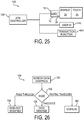
- FIG. 3 is a block diagram illustrating an example of the secure display device 10 coupled with a touch screen 34 receiving display input from an application running on a (host) processor (or computer) 38.
- Input from the touch screen 34 is passes through a secure cryptographic device (SCD) 36.
- the output of SCD 36 may be encrypted data or clear text.
- a universal serial bus (USB) connection is employed to couple the SCD 36 with the processor 38.
- the processor 38 provides data representative of display data (e.g., pictorial or graphical data) to SDD input 12.
- the removal detector 26 is employed to determine if the SDD 10 is securely coupled with the display 30. In an example embodiment, the removal detector is operable to disable the SDD 10 upon detecting removal of the SDD 10 from the display 30 or tampering of the SDD 10
- the SCD 36 may also be coupled with the SDD 10 via the communication interface. This can allow the SDD 10 to determine whether inputs received via the touch screen 34 are being encrypted.
- the SDD 10 and SCD 36, and processor 38 are illustrated as separate components, those skilled in the art should readily appreciate that in at least one embodiment any of the SDD10, SCD 36, and processor 38 may be combined into a single component.
- the SDD 10 and SCD 36 may be combined.
- SDD 10,SCD 36, and processor 38 may be combined.
- SCD 36 can indicate to SDD 10 that it is operating in a clear text mode.
- the SDD will limit operations to the first (partial takeover) mode and the second (takeover) mode while the SCD 36 is operating in clear text mode.
- the SDD 10 may allow operation in the third (pass through) mode when the SCD 36 is operating in either an encrypted mode (where screen coordinates are sent encrypted) or in Restricted mode (where only data indicating whether the touch screen 34 was touched or locations available for touch input on touch screen 34 are limited) .
- a trusted application running on processor 38 may be allowed to select the operational mode of SDD 10, SCD 36 or both SDD 10 and SCD 36.
- FIG. 4 is a block diagram illustrating an example of an alternative configuration of the secure display device 10 being coupled with touch screen 34.
- graphical data is provided to the SDD input 12 by the SCD 36.
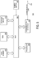
- Fig. 5 is a block diagram that illustrates a computer system 500 upon which an example embodiment may be implemented.
- computer system 500 may be employed to implement the functionality of SDD 10 described in FIGs 1-4 .
- the computer system 500 includes a bus 502 or other communication mechanism for communicating information and a processor 504 coupled with bus 502 for processing information.
- Computer system 500 also includes a main memory 506, such as random access memory (RAM) or other dynamic storage device coupled to bus 502 for storing information and instructions to be executed by processor 504.
- Main memory 506 also may be used for storing a temporary variable or other intermediate information during execution of instructions to be executed by processor 504.
- Computer system 500 further includes a read only memory (ROM) 508 or other static storage device coupled to bus 502 for storing static information and instructions for processor 504.
- a storage device 510 such as Flash disk a magnetic disk or optical disk, is provided and coupled to bus 502 for storing information and instructions.
- communication interface 16 allows for the receipt of configuration data, setup data, commands, or any other suitable communications.
- a communication link 520 may be coupled with any suitable device, such as SCD in FIG. 3
- removal device such as a tamper switch
- bus 502. If the removal detector (or tamper switch) 26 detects tampering (or removal) of the computer system 500 from a display panel, the removal device 26 may send a message to processor 504.
- An aspect of the example embodiment is related to the use of computer system 500 for implementing a secure display device.
- implementing a secure display device is provided by computer system 500 in response to processor 504 executing one or more sequences of one or more instructions contained in main memory 506.
- Such instructions may be read into main memory 506 from another computer-readable medium, such as storage device 510.
- Execution of the sequence of instructions contained in main memory 506 causes processor 504 to perform the process steps described herein.
- processors in a multi-processing arrangement may also be employed to execute the sequences of instructions contained in main memory 506.
- hard-wired circuitry may be used in place of or in combination with software instructions to implement an example embodiment.
- embodiments described herein are not limited to any specific combination of hardware circuitry and software.
- Non-volatile media include for example optical or magnetic disks, such as storage device 510.
- Volatile media include dynamic memory such as main memory 506.
- Transmission media include coaxial cables, copper wire and fiber optics, including the wires that comprise bus 502. Transmission media can also take the form of acoustic or light waves such as those generated during radio frequency (RF) and infrared (IR) data communications.
- RF radio frequency
- IR infrared
- Computer-readable media include for example floppy disk, a flexible disk, hard disk, magnetic cards, paper tape, any other physical medium with patterns of holes, a RAM, a PROM, an EPROM, a FLASHPROM, CD, DVD or any other memory chip or cartridge, or any other medium from which a computer can read.
- FIG. 6 is an example of a screen display 60 for a first security (e.g., secure) state.
- an icon 62 provides a visual representation of the security state.
- the icon 62 may include a background 64.
- the color of the background 64 may be selected (for example green) to indicate that data (e.g., PIN) entry is secure (e.g., a protected mode).
- the icon may also include a locked padlock 66, which in the locked position indicates touch screen inputs are secure. Additional text 68, 69 may also be employed to indicate that the display is in a protected mode.
- FIG. 7 is an example of a screen display 70 for a second (e.g., insecure) state.
- the icon 72 in the unprotected mode is different than the icon in the protected mode.
- the background 74 may be of a different color (for example red) than the color of the background 64 in FIG. 6 .
- the icon 72 comprises an unlocked padlock 76.
- FIGs. 6 and 7 use padlocks 66, 76 to indicate whether the display is in a protected or unprotected state
- padlocks 66, 76 any suitable icon may be employed to indicate secure and unprotected modes.
- the screen displays in FIGs 6 and 7 can be employed to prevent a customer from inadvertently disclosing a PIN to a malicious program. For example, when operating in an unprotected mode, at least a portion of the screen display is not controlled or that touch screen inputs are not being encrypted, or both.
- the icon 72 in FIG. 7 can be employed to indicate an unprotected mode.
- screen displays 60, 70 may vary over time. For example when first changing from a protected mode to an unprotected mode, icon 70 may appear in a popup window in the middle of the screen for a predefined time period, move to the top of the screen, shrink and/or move to another location, such as a corner of the screen display.
- additional information may be obtained from icons 62, 72.
- a help screen may displayed that indicates the current security state, and in particular embodiments may indicate the reason for the current security state (e.g., whether screen inputs are encrypted or restricted).
- FIG. 8 illustrates an example of a display 78 when entering a protected mode.
- the icon 62 appears in the middle of the screen and overlays the output for a short period of time to bring attention to the user that the display 78 is now in a protected (e.g., PIN entry) mode. After a time period, the screen may change to the screen 60 previously illustrated in FIG. 6 .
- a protected e.g., PIN entry
- FIG. 9 illustrates an example of a display 80 when entering an unprotected mode.
- the icon 72 appears in the middle of the screen and overlays the output for a short period of time to bring attention to the user that the display 80 is now in an unprotected (e.g., not a PIN entry) mode. After a time period, the screen may change to the screen 70 previously illustrated in FIG. 7 .
- FIG. 10 illustrates an example of display 82 presented on a display while in an unprotected mode.
- This display 82 employs a colored border 84 around a border to indicate the unprotected mode.
- the border 84 may be a first color (e.g., green) to indicate a protected mode.
- Display 82 may be presented in a partial takeover mode, where a SDD generates the border.
- FIG. 11 illustrates an example of a display 86 in a protected mode.
- the display 86 employs a colored border 88 to indicate the mode.
- the border 88 may be a second color (e.g., red, a color different than the first color employed in FIG. 10 ) to indicate an unprotected mode.
- Display 86 may be presented in a partial takeover mode, where a SDD generates the border.
- FIG. 12 illustrates yet another example of a display 90 employing an icon in a corner 92 of the display 90 to indicate a secure mode.
- the icon is a locked padlock 66, however, those skilled in the art should readily appreciate that any suitable icon may be employed. Moreover, those skilled in the art should readily appreciate that the position of the icon (corner 92) was selected merely for ease of illustration as the icon may be located in any suitable location.
- FIG. 13 illustrates an example of a touch screen display 94 in a Restricted (or Limited) Touch mode. In this mode, inputs are limited to areas 96, 98, 100, 102, 104, 106, 108, 110, 112. Inputs from other areas of the display 94 are ignored.
- the restricted touch screen may be implemented by a SCD, such as SCD 36 described in FIGs 3 and 4 .
- FIGs 14-24 illustrate an example of a sequence of displays that can be used in a fuel pump application.
- the first display 114 in the sequence prompts a user to either buy petrol (fuel) or apply for a petrol (e.g., credit) card via icons 116 and 118 respectively.
- the unlocked padlock 76 icon is displayed to indicate to the user that inputs at the display 114 are not protected.
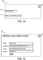
- the display 120 illustrated in FIG. 15 is presented when the user selects icon 118 in the display 114 presented in FIG. 14 .
- the display 120 provides fields for a user to enter their name, address, email address and a phone number.
- the unlocked padlock 76 indicates that data entered into this screen is not protected. After the user enters their data and presses the submit button, the display 122 is presented to the user providing the user with information regarding the processing of the application. The unlocked padlock 76 indicates that any data entered into this screen is unprotected.
- the display 124 illustrated in FIG. 17 is presented when the user selects icon 116 in the display 114 presented in FIG. 14 .
- the display 124 instructs the user to insert their card (e.g., petrol, fuel, credit, or any suitable card) for making the purchase.
- their card e.g., petrol, fuel, credit, or any suitable card
- the icon presented in display 124 shows a card going into a magstripe reader, this is merely or ease of illustration as wireless cards may also be employed.
- the unlocked padlock 76 indicates that data entered into this screen is unprotected.
- the card reader may be an encrypting card reader.
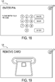
- display 126 in FIG. 18 is displayed. The user is prompted to enter their PIN.
- the icon 66 is presented to indicate that display 126 is protected.
- display 126 is presented by a SDD in takeover mode. If the card entry is a secure card with PIN entry, the user may then see a display similar to display 128 illustrated in FIG. 19 .
- the display 128 prompts the user to remove their card from the card reader.
- the unlocked padlock 76 indicates that the display 128 is unprotected.
- the use may be presented with the display 130 illustrated in FIG. 20 .
- This display indicates that the user should begin fueling.
- the unlocked padlock 76 indicates that the display 130 is unprotected.
- the user may be presented with display 132 illustrated in FIG. 21 .
- the display 132 instructs the user to push the "Done" button when the user has completed refueling.
- the unlocked padlock 76 on the display 132 indicates that the display 132 is unprotected.
- the display 134 in FIG. 22 may be presented to the user prompting the user to input whether they would like to a receipt and/or enter their mileage.
- the unlocked icon on the display 134 indicates that the display 134 is unprotected. If the user elects to enter their mileage, the display 136 is presented to the user.
- the unlocked padlock 76 indicates that the display 136 is unprotected.
- the display 138 is presented to the user if the user elects to print a receipt in the display 134 in FIG. 22 .
- the unlocked padlock 76 indicates that the display 138 is unprotected.
- FIG. 25 is an example of an automated banking machine (such as an automated teller machine or "ATM") 140 with a secure display device 10.
- the ATM 140 comprises display 30 with a touch screen 34 coupled to SDD 10. Removal detector 26 is employed to detect whether SDD 10 is properly coupled with display 30.
- the user identification device 142 may be any satiable device for determining the identity of a customer. Examples of user identification device include, but are not limited to a magnetic stripe (card) reader, a radio frequency identifier (RFID) reader, a wireless (such as WIFI, BLUETOOTH, or near field communication "NFC”) reader, biometric reader, or any combination of the aforementioned user identification devices.
- the ATM 140 also includes a transaction function device 144.
- the transaction function device 84 may include, but is not limited to, a cash dispenser, a cash receiver, a cash recycler, a check depositing device, receipt printer, or any other device or combination of devices for conducting a financial transaction.
- the ATM controller 146 comprises logic for conducting financial transactions.
- the ATM controller 146 may be co-located with the ATM 140, or in particular embodiments, may be located remotely.
- the ATM controller 146 may be considered trusted and thus be allowed to change the operating state of the SDD 10.
- the ATM controller 80 may have the SDD 10 operate in the second (takeover) mode while obtaining PIN inputs, and have the SDD 10 operate in any other mode at other times, such as for example, operating in the pass through mode while no transactions are being conducted to allow advertisements to be presented on the display.
- multiple outputs operating in different modes may be provided to display 30 at the same time.
- a first portion of the display 30 can be used for performing financial transactions and may operate in either the first (partial takeover) or second (takeover) modes, while a second portion of the screen may output advertisements and operate in the third (pass through) mode.
- a methodology 150 in accordance with an example embodiment will be better appreciated with reference to FIG. 26 . While, for purposes of simplicity of explanation, the methodology 150 of FIG. 26 is shown and described as executing serially, it is to be understood and appreciated that the example embodiment is not limited by the illustrated order, as some aspects could occur in different orders and/or concurrently with other aspects from that shown and described herein. Moreover, not all illustrated features may be required.
- the methodology 150 described herein is suitably adapted to be implemented in hardware, software when executed by a processor, or a combination thereof. For example, methodology 150 may be implemented by secure display logic 22 ( Figs. 1-4 ) or processor 508 in FIG. 5 .
- the screen data is received.
- the screen data may include graphical data to be output on a display.
- the operational mode is determined.
- the screen data is processed depending upon the operational mode.
- PASS THROUGH If the current operational mode at 154 is a "pass through" mode, (PASS THROUGH) then all screen data is forwarded to the display unmodified as illustrated at 156. Unlike takeover mode or partial takeover mode, no indication would be provided to indicate whether the touch screen is in a protected or unprotected mode. In an example embodiment, touch inputs in this mode would be encrypted or restricted to prevent PIN luring or phishing attacks.
- the screen data is ignored or discarded as indicated at 158.
- the SDD outputs a selected, predefined display.
- multiple outputs may be provided in a sequence. For example, performing the sequence illustrated in FIGs 13-24 .
- a cash withdrawal transaction at an ATM for example the ATM 140 illustrated in FIG.
- a first screen for requesting user identification e.g., insert a magstripe card, wait for a wireless signal from a device associated with a user, or wait for a biometric input
- a second screen requesting a PIN input may be followed by a third screen requesting the amount of the withdrawal, etc.
- a visual representation such as an icon may be provided to the display to indicate whether the display is secure. For example, if a removal device detects tampering, a message may be output on the display indicating tampering has occurred or that the device is unavailable.
- the screen data is provided to the display, however, other graphical data is provided to overlay at least a portion of the screen data.
- screen data may be forwarded to the display and an overlay with a visual indication, such as an icon may be provided to overlay the screen data to indicate whether the touch screen inputs of an associated display are secure as indicated by 160.
- a visual indication such as an icon may be provided to overlay the screen data to indicate whether the touch screen inputs of an associated display are secure as indicated by 160.
- touch screen inputs are being encrypted or restricted, the touch screen may be considered secure even though some elements on the display are insecure.
- a visual representation may be provided that indicates the display and/or touch screen inputs are insecure.
Description
- The present disclosure relates generally to display devices.
- A touch screen allows the user of a terminal to enter a menu selection or data by placing a finger or other object at a location on the display screen that corresponds to the menu item, function or data numeral to be entered. A touch sensitive element detects the coordinates of the touch event and the meaning of the touch event is determined by the coordinate location and the corresponding menu or data button displayed on the screen associated with the touch sensitive element. When a touch screen is utilized to enter data such as a secret personal identification ("PIN") number, the PIN number should be protected by encryption prior to being communicated to any external resource. International patent applications
WO 2011/051757 A1 andWO 2006/034713 A1 disclose secure display devices with different security modes. - The accompanying drawings incorporated herein and forming a part of the specification illustrate the example embodiments.
-
FIG. 1 is a block diagram illustrating an example of a secure display device. -
FIG. 2 is a block diagram illustrating an example of a secure display device coupled with a flat panel display. -
FIG. 3 is a block diagram illustrating an example of the secure display device coupled with a touch screen receiving display input from an application running on a processor. -
FIG. 4 is a block diagram illustrating an example of the secure display device coupled with a touch screen receiving display input from a secure cryptographic device. -
FIG. 5 is a block diagram that illustrates a computer system upon which an example embodiment may be implemented. -
FIG. 6 is an example of a screen display for a protected data entry mode. -
FIG. 7 is an example of a screen display for an unprotected data entry mode. -
FIG. 8 illustrates an example of a display when entering a protected mode. -
FIG. 9 illustrates an example of a display when entering an unprotected mode. -
FIG. 10 illustrates an example of display in an unprotected mode employs a colored border to indicate the mode. -
FIG. 11 illustrates an example of a display in a protected mode that a colored border to indicate the mode. -
FIG. 12 illustrates yet another example of a display employing an icon to indicate a secure mode. -
FIG. 13 illustrates an example of a touch screen in a Restricted Touch mode. -
FIGs 14-24 illustrate an example of a sequence of displays that can be used in a fuel pump application. -
FIG. 25 is an example of an automated banking machine with a secure display device. -
FIG. 26 is a block diagram illustrating a methodology for handling data for a screen display. - The following presents a simplified overview of the example embodiments in order to provide a basic understanding of some aspects of the example embodiments. This overview is not an extensive overview of the example embodiments. It is intended to neither identify key or critical elements of the example embodiments nor delineate the scope of the appended claims. Its sole purpose is to present some concepts of the example embodiments in a simplified form as a prelude to the more detailed description that is presented later.
- In accordance with an example embodiment, there is disclosed herein, a secure display device (SDD) that includes hardware that can be positioned between a computing device or a processor, and a display such as a flat panel display (FPD). Display data from the PC/CPU to the FPD is transmitted through the SDD.
- This description provides examples not intended to limit the scope of the appended claims. The figures generally indicate the features of the examples, where it is understood and appreciated that like reference numerals are used to refer to like elements. Reference in the specification to "one embodiment" or "an embodiment" or "an example embodiment" means that a particular feature, structure, or characteristic described is included in at least one embodiment described herein and does not imply that the feature, structure, or characteristic is present in all embodiments described herein.
-
FIG. 1 is a block diagram illustrating an example of a secure display device (SDD) 10. Thesecure display device 10 comprises aSDD input 12, aSDD output 14, acommunication interface 16, and apower input 18 coupled with apower supply 20 that are coupled with asecure display logic 22. "Logic", as used herein, includes but is not limited to hardware, firmware, software and/or combinations of each to perform a function(s) or an action(s), and/or to cause a function or action from another component. For example, based on a desired application or need, logic may include a software controlled microprocessor, discrete logic such as an application specific integrated circuit (ASIC), a programmable/programmed logic device, memory device containing instructions, or the like, or combinational logic embodied in hardware. Logic may also be fully embodied as software that performs the desired functionality when executed by a processor. In an example embodiment, the secure display device further comprises amemory 24. In an example embodiment, thesecure display device 10 further comprises a removal detector (e.g., a tamper switch) 26. In the illustrated example, theSDD input 12, theSDD output 14, thecommunication interface 16, thepower input 18,power supply 20, thesecure display logic 22, thememory 24, and thetamper switch 26 are mounted on a printed circuit board (PCB) 28. - In an example embodiment, the
SDD input 12 obtains display data (such as, for example, graphical data) from an application being executed by a Central Processing Unit (CPU) or a Personal Computer (PC) through a display controller. TheSDD input 12 may employ any suitable wired or wireless protocol. For example, in particular embodiments, theSDD input 12 supports a LVDS (Low Voltage Differential Signaling) Graphics port and is field programmable for different formats. - The
SDD output 14 is operable to be coupled with a display. TheSDD output 14 may employ any suitable wired or wireless protocol to communicate with the display and is field programmable. For example, theSDD output 14 can support LVDS. - In an example embodiment, the
secure display logic 22 is operable to obtain data representative of a screen display via theSDD input 12. Thesecure display logic 22 is operable to selectively output the data representative of the screen display via the screen display output based at least in part on an operational mode. For example, in a first operation mode (which may also be referred to herein as a "partial takeover" mode), thesecure display logic 22 passes the data representative of the screen display to thescreen display output 14 and also causes data to be passed through thescreen display output 14 that is representative of a predefined graphic that will at least partial overlay the screen display.FIGs. 6 and 7 described herein infra illustrate examples of a partial overlay of a screen display. - In an example embodiment, the
secure display logic 22 can operate in a second operational mode where the output of the display coupled withSDD output 14 is controlled (which may be referred to herein as "takeover" mode). In this operational mode, a selected screen is provided to the display. Data representative of a screen display received in this operational mode is ignored or discarded. - In an example embodiment, the
secure display logic 22 can operate in a third mode where data representative of a screen display is passed to thescreen display output 14 to be displayed unmodified (which may also be referred to herein as a "pass through" mode). As will be discussed in more detail herein, an example embodiment, the third display mode may be allowed in limited circumstances. For example, where the display is a touch screen display, the third display mode may be limited to times when inputs to the touch screen display are encrypted. As another example, the third display mode may be limited to times when the touch screen is operating in a "Restricted Touch" mode where the touch screen acts as a virtual key and the location (coordinates) of where a touch screen input was received are not provided. For example, while watching a video in full screen ("pass through") mode, if an input is received on the touch screen, the touch screen merely provides an indication that the screen was touched to pause the video, and the secure display logic may switch to another operational mode (e.g.., the first operational mode) while the video is paused. Thescreen display logic 22 may obtain data indicating the current operating mode of a touch screen from the touch screen or a cryptographic screen display element (not shown, see e.g.,FIG. 3 ) associated with the touch screen viacommunication interface 16. - In another example embodiment, a Restricted Touch mode may restrict touch locations available on a screen. This can prevent PIN Luring/Phishing attacks during normal application mode. For example, a PIN Luring/Phishing attack may try to change a standard application picture (e.g., graphic) to a false PIN pad picture and thereby pretend to be in a PIN entry mode. This Restricted Touch mode, by restricting screen locations for input, can prevent entry of some of the numbers of the false PIN pad
- As will be described in more detail herein (see e.g.,
FIGs 6 and 7 infra), the screen output provided to a display viaSDD output 12 may include visual representation to indicate whether the touch screen is in a protected or unprotected mode. The visual representation may include an icon. For example, an unlocked padlock would indicate an unprotected mode while a locked padlock would indicate a secure mode. In addition, the visual representation may include a color scheme to indicate whether the touch screen is in a secure or insecure operating mode. For example, an icon with a green background may indicate a protected mode while an icon with a red background may indicate an unprotected mode. As yet another example, the visual representation may include text indicating the mode (e.g., protected mode, unprotected mode , application mode, test mode, etc.). - As will be illustrated herein infra, the removal detector (or tamper switch) 26 can protect a connection between the
SDD output 14 and a display device. The removal detector may be operable to detect changes in force, pressure, magnetism, capacitance, and inductance, or any combination thereof, between theSDD output 14 and the display device coupled with theSDD output 14. In an example embodiment, theremoval detector 26 comprises a mesh with electrically conductive tracks. - In an example embodiment, the
secure display logic 22 is operable to ignore data received via theSDD input 12 and provide data representative of a predefined screen output toSDD output 14 responsive to theremoval detector 26 detecting tampering. In particular embodiments, thesecure display logic 22 is operable to send a message via theSDD input 12, thecommunication interface 16, or both, to a predefined destination (such as, for example, a host CPU) responsive to theremoval detector 26 detecting tampering. - In an example embodiment, the
communication interface 16 is operable to receive device configuration data, device setup data, graphics, or device initialization commands. The communication interface is field programmable and can support I2C (Inter integrated Circuit), SPI (Serial Peripheral Interface), UART (Universal Asynchronous Receiver-Transmitter), 1 wire, or any other suitable protocol. In particular embodiments, communications with thecommunication interface 16 are cryptographically controlled. For example, wherein commands received by the communication interface are encrypted or authenticated by message authentication code (MAC) or signature schemes. Cryptographic mechanisms could be done by one of a group consisting of Advanced Encryption Standard (AES), Triple Data Encryption Standard (3DES), Rivest, Shamir, and Adleman (RSA), and Elliptical Curve Cryptography (ECC). - In an example embodiment, control of the
secure display logic 22 may be accomplished by an external device viacommunication interface 16. For example, a secure cryptographic device associated with a display or a trusted application, which in an example embodiment may employ cryptographically secure communications, may provide data to thesecure display logic 22 to select the operating state, or may send data indicating the operating state of the display. For example,secure display logic 22 may be configured to limit the availability of the pass through mode to times when touch inputs are encrypted order restricted touch control. Signals from a secure cryptographic device associated with the screen can indicate whether screen inputs are encrypted. -
FIG. 2 is a block diagram illustrating an example of asecure display device 10 coupled with aflat panel display 30. This example illustrates thePCB 28 where components on afirst side 42 of thePCB 28 are considered secure. In the illustrated example, theSDD output 14 andinput 32 are located on thefirst side 42 of thePCB 28. This prevents access to theSDD output 14,input 32, and the link (e.g., cable) 40. Removal detector (tamper switch 26) protects the first (secure)side 42 of thePCB 28. For example, removal of thePCB 28 from theflat panel display 30 will trigger theremoval detector 26. Thesecond side 44 of thePCB 28 is considered insecure. -
FIG. 3 is a block diagram illustrating an example of thesecure display device 10 coupled with atouch screen 34 receiving display input from an application running on a (host) processor (or computer) 38. Input from thetouch screen 34 is passes through a secure cryptographic device (SCD) 36. The output ofSCD 36 may be encrypted data or clear text. A universal serial bus (USB) connection is employed to couple theSCD 36 with theprocessor 38. Theprocessor 38 provides data representative of display data (e.g., pictorial or graphical data) toSDD input 12. Theremoval detector 26 is employed to determine if theSDD 10 is securely coupled with thedisplay 30. In an example embodiment, the removal detector is operable to disable theSDD 10 upon detecting removal of theSDD 10 from thedisplay 30 or tampering of theSDD 10 - In particular embodiments, the
SCD 36 may also be coupled with theSDD 10 via the communication interface. This can allow theSDD 10 to determine whether inputs received via thetouch screen 34 are being encrypted. Although theSDD 10 andSCD 36, andprocessor 38 are illustrated as separate components, those skilled in the art should readily appreciate that in at least one embodiment any of the SDD10,SCD 36, andprocessor 38 may be combined into a single component. For example, in one embodiment, theSDD 10 andSCD 36 may be combined. In another embodiment,SDD 10,SCD 36, andprocessor 38 may be combined. - For example,
SCD 36 can indicate toSDD 10 that it is operating in a clear text mode. The SDD will limit operations to the first (partial takeover) mode and the second (takeover) mode while theSCD 36 is operating in clear text mode. TheSDD 10 may allow operation in the third (pass through) mode when theSCD 36 is operating in either an encrypted mode (where screen coordinates are sent encrypted) or in Restricted mode (where only data indicating whether thetouch screen 34 was touched or locations available for touch input ontouch screen 34 are limited) . In particular embodiments, a trusted application running onprocessor 38 may be allowed to select the operational mode ofSDD 10,SCD 36 or bothSDD 10 andSCD 36. -
FIG. 4 is a block diagram illustrating an example of an alternative configuration of thesecure display device 10 being coupled withtouch screen 34. In this embodiment, graphical data is provided to theSDD input 12 by theSCD 36. -
Fig. 5 is a block diagram that illustrates acomputer system 500 upon which an example embodiment may be implemented. For example,computer system 500 may be employed to implement the functionality ofSDD 10 described inFIGs 1-4 . - In an example embodiment, the
computer system 500 includes abus 502 or other communication mechanism for communicating information and aprocessor 504 coupled withbus 502 for processing information.Computer system 500 also includes amain memory 506, such as random access memory (RAM) or other dynamic storage device coupled tobus 502 for storing information and instructions to be executed byprocessor 504.Main memory 506 also may be used for storing a temporary variable or other intermediate information during execution of instructions to be executed byprocessor 504.Computer system 500 further includes a read only memory (ROM) 508 or other static storage device coupled tobus 502 for storing static information and instructions forprocessor 504. Astorage device 510, such as Flash disk a magnetic disk or optical disk, is provided and coupled tobus 502 for storing information and instructions. - In an example embodiment,
communication interface 16 allows for the receipt of configuration data, setup data, commands, or any other suitable communications. Acommunication link 520 may be coupled with any suitable device, such as SCD inFIG. 3 - In particular embodiments, removal device (such as a tamper switch) 26 is coupled to
bus 502. If the removal detector (or tamper switch) 26 detects tampering (or removal) of thecomputer system 500 from a display panel, theremoval device 26 may send a message toprocessor 504. - An aspect of the example embodiment is related to the use of
computer system 500 for implementing a secure display device. According to an example embodiment, implementing a secure display device is provided bycomputer system 500 in response toprocessor 504 executing one or more sequences of one or more instructions contained inmain memory 506. Such instructions may be read intomain memory 506 from another computer-readable medium, such asstorage device 510. Execution of the sequence of instructions contained inmain memory 506 causesprocessor 504 to perform the process steps described herein. One or more processors in a multi-processing arrangement may also be employed to execute the sequences of instructions contained inmain memory 506. In alternative embodiments, hard-wired circuitry may be used in place of or in combination with software instructions to implement an example embodiment. Thus, embodiments described herein are not limited to any specific combination of hardware circuitry and software. - The term "computer-readable medium" as used herein refers to any medium that participates in providing instructions to
processor 504 for execution. Such a medium may take many forms, including but not limited to non-volatile media, volatile media, and transmission media. Non-volatile media include for example optical or magnetic disks, such asstorage device 510. Volatile media include dynamic memory such asmain memory 506. Transmission media include coaxial cables, copper wire and fiber optics, including the wires that comprisebus 502. Transmission media can also take the form of acoustic or light waves such as those generated during radio frequency (RF) and infrared (IR) data communications. Common forms of computer-readable media include for example floppy disk, a flexible disk, hard disk, magnetic cards, paper tape, any other physical medium with patterns of holes, a RAM, a PROM, an EPROM, a FLASHPROM, CD, DVD or any other memory chip or cartridge, or any other medium from which a computer can read. -
FIG. 6 is an example of ascreen display 60 for a first security (e.g., secure) state. In this example, anicon 62 provides a visual representation of the security state. Theicon 62 may include abackground 64. The color of thebackground 64 may be selected (for example green) to indicate that data (e.g., PIN) entry is secure (e.g., a protected mode). The icon may also include a lockedpadlock 66, which in the locked position indicates touch screen inputs are secure.Additional text -
FIG. 7 is an example of ascreen display 70 for a second (e.g., insecure) state. Theicon 72 in the unprotected mode is different than the icon in the protected mode. For example, thebackground 74 may be of a different color (for example red) than the color of thebackground 64 inFIG. 6 . In addition, theicon 72 comprises anunlocked padlock 76. - Although the examples in
FIGs. 6 and 7 use padlocks 66, 76 to indicate whether the display is in a protected or unprotected state, those skilled in the art should readily appreciate that any suitable icon may be employed to indicate secure and unprotected modes. The screen displays inFIGs 6 and 7 can be employed to prevent a customer from inadvertently disclosing a PIN to a malicious program. For example, when operating in an unprotected mode, at least a portion of the screen display is not controlled or that touch screen inputs are not being encrypted, or both. Theicon 72 inFIG. 7 can be employed to indicate an unprotected mode. - In particular embodiments, screen displays 60, 70 may vary over time. For example when first changing from a protected mode to an unprotected mode,
icon 70 may appear in a popup window in the middle of the screen for a predefined time period, move to the top of the screen, shrink and/or move to another location, such as a corner of the screen display. - In an example embodiment, additional information may be obtained from
icons icon -
FIG. 8 illustrates an example of adisplay 78 when entering a protected mode. Theicon 62 appears in the middle of the screen and overlays the output for a short period of time to bring attention to the user that thedisplay 78 is now in a protected (e.g., PIN entry) mode. After a time period, the screen may change to thescreen 60 previously illustrated inFIG. 6 . -
FIG. 9 illustrates an example of adisplay 80 when entering an unprotected mode. Theicon 72 appears in the middle of the screen and overlays the output for a short period of time to bring attention to the user that thedisplay 80 is now in an unprotected (e.g., not a PIN entry) mode. After a time period, the screen may change to thescreen 70 previously illustrated inFIG. 7 . -
FIG. 10 illustrates an example ofdisplay 82 presented on a display while in an unprotected mode. Thisdisplay 82 employs acolored border 84 around a border to indicate the unprotected mode. For example theborder 84 may be a first color (e.g., green) to indicate a protected mode.Display 82 may be presented in a partial takeover mode, where a SDD generates the border. -
FIG. 11 illustrates an example of adisplay 86 in a protected mode. Thedisplay 86 employs acolored border 88 to indicate the mode. For example, theborder 88 may be a second color (e.g., red, a color different than the first color employed inFIG. 10 ) to indicate an unprotected mode.Display 86 may be presented in a partial takeover mode, where a SDD generates the border. -
FIG. 12 illustrates yet another example of adisplay 90 employing an icon in acorner 92 of thedisplay 90 to indicate a secure mode. In the illustrated example, the icon is a lockedpadlock 66, however, those skilled in the art should readily appreciate that any suitable icon may be employed. Moreover, those skilled in the art should readily appreciate that the position of the icon (corner 92) was selected merely for ease of illustration as the icon may be located in any suitable location. -
FIG. 13 illustrates an example of atouch screen display 94 in a Restricted (or Limited) Touch mode. In this mode, inputs are limited toareas display 94 are ignored. The restricted touch screen may be implemented by a SCD, such asSCD 36 described inFIGs 3 and 4 . -
FIGs 14-24 illustrate an example of a sequence of displays that can be used in a fuel pump application. Thefirst display 114 in the sequence prompts a user to either buy petrol (fuel) or apply for a petrol (e.g., credit) card viaicons unlocked padlock 76 icon is displayed to indicate to the user that inputs at thedisplay 114 are not protected. - The
display 120 illustrated inFIG. 15 is presented when the user selectsicon 118 in thedisplay 114 presented inFIG. 14 . Thedisplay 120 provides fields for a user to enter their name, address, email address and a phone number. Theunlocked padlock 76 indicates that data entered into this screen is not protected. After the user enters their data and presses the submit button, thedisplay 122 is presented to the user providing the user with information regarding the processing of the application. Theunlocked padlock 76 indicates that any data entered into this screen is unprotected. - The
display 124 illustrated inFIG. 17 is presented when the user selectsicon 116 in thedisplay 114 presented inFIG. 14 . Thedisplay 124 instructs the user to insert their card (e.g., petrol, fuel, credit, or any suitable card) for making the purchase. Note that although the icon presented indisplay 124 shows a card going into a magstripe reader, this is merely or ease of illustration as wireless cards may also be employed. Theunlocked padlock 76 indicates that data entered into this screen is unprotected. Although thedisplay 124 is unprotected, in an example embodiment, the card reader may be an encrypting card reader. - After the card is entered,
display 126 inFIG. 18 is displayed. The user is prompted to enter their PIN. Theicon 66 is presented to indicate thatdisplay 126 is protected. In an example embodiment,display 126 is presented by a SDD in takeover mode. If the card entry is a secure card with PIN entry, the user may then see a display similar to display 128 illustrated inFIG. 19 . Thedisplay 128 prompts the user to remove their card from the card reader. Theunlocked padlock 76 indicates that thedisplay 128 is unprotected. - Once the transaction is approved, the use may be presented with the
display 130 illustrated inFIG. 20 . This display indicates that the user should begin fueling. Theunlocked padlock 76 indicates that thedisplay 130 is unprotected. In an example embodiment, the user may be presented withdisplay 132 illustrated inFIG. 21 . Thedisplay 132 instructs the user to push the "Done" button when the user has completed refueling. Theunlocked padlock 76 on thedisplay 132 indicates that thedisplay 132 is unprotected. - In an example embodiment, after the user is fueling, the
display 134 inFIG. 22 may be presented to the user prompting the user to input whether they would like to a receipt and/or enter their mileage. The unlocked icon on thedisplay 134 indicates that thedisplay 134 is unprotected. If the user elects to enter their mileage, thedisplay 136 is presented to the user. Theunlocked padlock 76 indicates that thedisplay 136 is unprotected. - The
display 138 is presented to the user if the user elects to print a receipt in thedisplay 134 inFIG. 22 . Theunlocked padlock 76 indicates that thedisplay 138 is unprotected. -
FIG. 25 is an example of an automated banking machine (such as an automated teller machine or "ATM") 140 with asecure display device 10. TheATM 140 comprisesdisplay 30 with atouch screen 34 coupled toSDD 10.Removal detector 26 is employed to detect whetherSDD 10 is properly coupled withdisplay 30. Theuser identification device 142 may be any satiable device for determining the identity of a customer. Examples of user identification device include, but are not limited to a magnetic stripe (card) reader, a radio frequency identifier (RFID) reader, a wireless (such as WIFI, BLUETOOTH, or near field communication "NFC") reader, biometric reader, or any combination of the aforementioned user identification devices. TheATM 140 also includes atransaction function device 144. Thetransaction function device 84 may include, but is not limited to, a cash dispenser, a cash receiver, a cash recycler, a check depositing device, receipt printer, or any other device or combination of devices for conducting a financial transaction. TheATM controller 146 comprises logic for conducting financial transactions. TheATM controller 146 may be co-located with theATM 140, or in particular embodiments, may be located remotely. - In an example embodiment, the
ATM controller 146 may be considered trusted and thus be allowed to change the operating state of theSDD 10. For example, while conducting a financial transaction theATM controller 80 may have theSDD 10 operate in the second (takeover) mode while obtaining PIN inputs, and have theSDD 10 operate in any other mode at other times, such as for example, operating in the pass through mode while no transactions are being conducted to allow advertisements to be presented on the display. As another example, multiple outputs operating in different modes may be provided to display 30 at the same time. For example, a first portion of thedisplay 30 can be used for performing financial transactions and may operate in either the first (partial takeover) or second (takeover) modes, while a second portion of the screen may output advertisements and operate in the third (pass through) mode. - In view of the foregoing structural and functional features described above, a
methodology 150 in accordance with an example embodiment will be better appreciated with reference toFIG. 26 . While, for purposes of simplicity of explanation, themethodology 150 ofFIG. 26 is shown and described as executing serially, it is to be understood and appreciated that the example embodiment is not limited by the illustrated order, as some aspects could occur in different orders and/or concurrently with other aspects from that shown and described herein. Moreover, not all illustrated features may be required. Themethodology 150 described herein is suitably adapted to be implemented in hardware, software when executed by a processor, or a combination thereof. For example,methodology 150 may be implemented by secure display logic 22 (Figs. 1-4 ) orprocessor 508 inFIG. 5 . - At 152, screen data is received. The screen data may include graphical data to be output on a display.
- At 154, the operational mode is determined. The screen data is processed depending upon the operational mode.
- If the current operational mode at 154 is a "pass through" mode, (PASS THROUGH) then all screen data is forwarded to the display unmodified as illustrated at 156. Unlike takeover mode or partial takeover mode, no indication would be provided to indicate whether the touch screen is in a protected or unprotected mode. In an example embodiment, touch inputs in this mode would be encrypted or restricted to prevent PIN luring or phishing attacks.
- If the current operational mode at 154 is a secure or "takeover" mode (TAKEOVER), the screen data is ignored or discarded as indicated at 158. In this mode, the SDD outputs a selected, predefined display. Depending on the task being performed, multiple outputs may be provided in a sequence. For example, performing the sequence illustrated in
FIGs 13-24 . As another example, for a cash withdrawal transaction at an ATM, (for example theATM 140 illustrated inFIG. 25 ), a first screen for requesting user identification (e.g., insert a magstripe card, wait for a wireless signal from a device associated with a user, or wait for a biometric input) may be followed by a second screen requesting a PIN input that is followed by a third screen requesting the amount of the withdrawal, etc. In particular embodiments, a visual representation such as an icon may be provided to the display to indicate whether the display is secure. For example, if a removal device detects tampering, a message may be output on the display indicating tampering has occurred or that the device is unavailable. - If, at 154, the operation mode is a "partial takeover" mode (PARTIAL TAKEOVER), the screen data is provided to the display, however, other graphical data is provided to overlay at least a portion of the screen data. For example, screen data may be forwarded to the display and an overlay with a visual indication, such as an icon may be provided to overlay the screen data to indicate whether the touch screen inputs of an associated display are secure as indicated by 160. For example, if touch screen inputs are being encrypted or restricted, the touch screen may be considered secure even though some elements on the display are insecure. If touch screen inputs are not secure (e.g., not encrypted or restricted), a visual representation may be provided that indicates the display and/or touch screen inputs are insecure.
- Described above are example embodiments. It is, of course, not possible to describe every conceivable combination of components or methodologies for purposes of describing the example embodiments, but one of ordinary skill in the art will recognize that many further combinations and permutations of the example embodiments are possible. The invention is defined by the appended claims.
Claims (21)
- An apparatus (10), comprising:a screen display input (12);a screen display output (14);and secure display logic (22)coupled with the screen display inputand the screen display output;the secure display logic is configured to obtain datarepresentative of a screen display via the screen display input;the secure display logic is configured to selectively output thedata representative of the screen display via the screen display output based on an operational mode;wherein in a first operational mode, the secure display logic is configured to output an overlay via the screen display output that overlays at least a portion of the screen display with apredefined graphic indicating a security state of the screen display;wherein in a second operational mode, the secure display logic is configured to prevent the data representative of the screen display from being output on the screen display output and instead provides a selected screen output to the screen display output;wherein a third operational mode, the secure display logic is configured to send the data representative of the screen displayto the screen display output unmodified, wherein the screen display input is encrypted or restricted.
- The apparatus set forth in claim 1, wherein the secure display logic is further configured while in the second operational mode to provide a visual indication of a security state of the display.
- The apparatus set forth in claim 2, wherein the secure display logic is further configured to communicate with a secure cryptographic device (36) associated with a display coupled with the screen display output.
- The apparatus set forth in claim 3, wherein the operational mode is based at least in part on an operational mode of the secure cryptographic device; and wherein the secure display logic is configured to operate in the third mode responsive to the secure cryptographic device being in an operational mode that encrypts inputs from the touch screen.
- The apparatus set forth in claim 4, further comprising a removal detector; wherein the secure display logic is configured to send a signal to disable the secure cryptographic device responsive to the removal detector detecting a removal event.
- The apparatus set forth in claim 5, wherein the secure display logic is configured to operate in the second mode responsive to receiving a signal from the secure cryptographic device indicative of a tampering event; and wherein the selected screen output indicates one of a group consisting of the display is not operational and data representative of a tampering event.
- The apparatus set forth in claim 3, wherein the secure display logic is at least in part controlled by the secure cryptographic device; wherein the secure display logic is configured to limit operations to the first operational mode or the second operational mode when the output of the secure cryptographic device is operating in a clear text mode.
- The apparatus set forth in claim 3, wherein the secure display logic is configured to output the data representative of the screen display via the screen display output based on the third operational mode when the output of the secure cryptographic device is operating in an encrypted text mode or in a restricted touch control mode.
- The apparatus set forth in claim 2, wherein the predefined graphic comprises one of a group consisting of a sequence of a plurality of predefined graphics and a video stream.
- The apparatus set forth in claim 2, further comprising a memory for storing the selected screen output and the predefined graphic.
- The apparatus set forth in claim 10, wherein the predefined graphic includes one of a group consisting of a first icon and a second icon corresponding to a security state of the display.
- The apparatus set forth in claim 11, wherein the first icon comprises visual representation of a locked padlock corresponding to a first security state.
- The apparatus set forth in claim 12, wherein the first icon comprises a first color corresponding to the first security state.
- The apparatus set forth in claim 13, wherein the second icon comprises a visual representation of an unlocked padlock corresponding to a second security state.
- The apparatus set forth in claim 14, wherein the second icon comprises a second color corresponding to the second security state.
- The apparatus set forth in claim 1, further comprising a removal detector that protects a connection between the screen display output and a display device coupled with the screen display output.
- The apparatus set forth in claim 16, wherein the removal detector is configured to detect one of a group consisting of force, pressure, magnetism, capacitance, and inductance.
- The apparatus set forth in claim 16, where the removal detector comprises a mesh with electrically conductive tracks.
- The apparatus set forth in claim 18, wherein the secure display logic is configured to operate in the second mode responsive to the removal detector detecting tampering.
- The apparatus set forth in claim 19, wherein the secure display logic is configured to send a message via one of a group consisting of the screen display input and the communication interface to a predefined destination responsive to the removal detector detecting tampering.
- A tangible, non-transitory computer readable medium of execution with instructions encoded thereon for execution by a processor, and when executed configured to:obtain data representative of a screen display; andselectively output the data representative of the screen display based at least in part on an operational mode;wherein in a first operational mode, at least a portion of the screen display is overlaid with a predefined graphic indicating a security state of the screen display;wherein in a second operational mode, the secure display logic is configured to prevent the data representative of the screen display from being output on the screen display output and instead provides a selected screen output to the screen display output;wherein a third operational mode, the secure display logic is configured to send the data representative of the screen display to the screen display output unmodified, wherein screen display input is encrypted or restricted.
Applications Claiming Priority (1)
| Application Number | Priority Date | Filing Date | Title |
|---|---|---|---|
| PCT/IB2016/000388 WO2017149343A1 (en) | 2016-03-02 | 2016-03-02 | Secure display device |
Publications (2)
| Publication Number | Publication Date |
|---|---|
| EP3423984A1 EP3423984A1 (en) | 2019-01-09 |
| EP3423984B1 true EP3423984B1 (en) | 2021-05-19 |
Family
ID=55697242
Family Applications (1)
| Application Number | Title | Priority Date | Filing Date |
|---|---|---|---|
| EP16715089.5A Active EP3423984B1 (en) | 2016-03-02 | 2016-03-02 | Secure display device |
Country Status (5)
| Country | Link |
|---|---|
| US (1) | US10915668B2 (en) |
| EP (1) | EP3423984B1 (en) |
| CN (1) | CN109478224A (en) |
| DK (1) | DK3423984T3 (en) |
| WO (1) | WO2017149343A1 (en) |
Families Citing this family (3)
| Publication number | Priority date | Publication date | Assignee | Title |
|---|---|---|---|---|
| CN208766800U (en) * | 2018-10-11 | 2019-04-19 | 中磊电子(苏州)有限公司 | It can detect and return the electronic device of tampering |
| USD953347S1 (en) * | 2019-09-02 | 2022-05-31 | Huawei Technologies Co., Ltd. | Electronic display for a wearable device presenting a graphical user interface |
| USD958837S1 (en) * | 2019-12-26 | 2022-07-26 | Sony Corporation | Display or screen or portion thereof with animated graphical user interface |
Family Cites Families (27)
| Publication number | Priority date | Publication date | Assignee | Title |
|---|---|---|---|---|
| US5768386A (en) | 1996-05-31 | 1998-06-16 | Transaction Technology, Inc. | Method and system for encrypting input from a touch screen |
| US8840016B1 (en) | 1998-04-17 | 2014-09-23 | Diebold Self-Service Systems Division Of Diebold, Incorporated | Banking system controlled responsive to data bearing records |
| US6317835B1 (en) | 1998-12-23 | 2001-11-13 | Radiant Systems, Inc. | Method and system for entry of encrypted and non-encrypted information on a touch screen |
| US6549194B1 (en) | 1999-10-01 | 2003-04-15 | Hewlett-Packard Development Company, L.P. | Method for secure pin entry on touch screen display |
| US6630928B1 (en) * | 1999-10-01 | 2003-10-07 | Hewlett-Packard Development Company, L.P. | Method and apparatus for touch screen data entry |
| US6715078B1 (en) | 2000-03-28 | 2004-03-30 | Ncr Corporation | Methods and apparatus for secure personal identification number and data encryption |
| AU2001280835A1 (en) | 2000-07-27 | 2002-02-13 | Eft Datalink, Incorporated | Value transfer system for unbanked customers |
| US8100323B1 (en) | 2002-12-26 | 2012-01-24 | Diebold Self-Service Systems Division Of Diebold, Incorporated | Apparatus and method for verifying components of an ATM |
| US7963843B2 (en) | 2003-03-28 | 2011-06-21 | Oneida Indian Nation | Cashless gaming system and method with monitoring |
| WO2006034713A1 (en) * | 2004-09-29 | 2006-04-06 | Sagem Denmark A/S | Secure display for atm |
| US8108317B2 (en) | 2005-08-31 | 2012-01-31 | Hand Held Products, Inc. | System and method for restricting access to a terminal |
| US8833646B1 (en) | 2005-12-20 | 2014-09-16 | Diebold Self-Service Systems Division Of Diebold, Incorporated | Banking system controlled responsive to data bearing records |
| CN101266704B (en) * | 2008-04-24 | 2010-11-10 | 张宏志 | ATM secure authentication and pre-alarming method based on face recognition |
| KR101517967B1 (en) * | 2008-07-07 | 2015-05-06 | 엘지전자 주식회사 | Controlling a Mobile Terminal |
| US8456429B2 (en) | 2009-07-30 | 2013-06-04 | Ncr Corporation | Encrypting touch-sensitive display |
| US20150161600A1 (en) * | 2009-10-26 | 2015-06-11 | Gmx Sas | Transactor for use in connection with transactions involving secure and non-secure information |
| DE102010060862A1 (en) | 2010-11-29 | 2012-05-31 | Wincor Nixdorf International Gmbh | Device for reading magnetic stripe and / or chip cards with touch screen for PIN input |
| JP2014512051A (en) | 2011-04-08 | 2014-05-19 | サーク・コーポレーション | A system for protecting PIN data using a capacitive touch detection terminal or PIN pad |
| WO2013022290A1 (en) | 2011-08-10 | 2013-02-14 | 노틸러스효성 주식회사 | Touch screen having integrated epp, and input information processing method for automated teller machine using same |
| US10102401B2 (en) * | 2011-10-20 | 2018-10-16 | Gilbarco Inc. | Fuel dispenser user interface system architecture |
| US20130145475A1 (en) * | 2011-12-02 | 2013-06-06 | Samsung Electronics Co., Ltd. | Method and apparatus for securing touch input |
| US9436940B2 (en) * | 2012-07-09 | 2016-09-06 | Maxim Integrated Products, Inc. | Embedded secure element for authentication, storage and transaction within a mobile terminal |
| US9268930B2 (en) * | 2012-11-29 | 2016-02-23 | Gilbarco Inc. | Fuel dispenser user interface system architecture |
| US20140195429A1 (en) | 2013-01-08 | 2014-07-10 | Cirque Corporation | Method for protecting cardholder data in a mobile device that performs secure payment transactions and which enables the mobile device to function as a secure payment terminal |
| EP2775421B1 (en) | 2013-03-05 | 2019-07-03 | Wincor Nixdorf International GmbH | Trusted terminal platform |
| CN104143066A (en) * | 2013-05-10 | 2014-11-12 | 中国银联股份有限公司 | Security information exchanging device |
| US20150161579A1 (en) * | 2013-12-11 | 2015-06-11 | Verifone, Inc. | Point of sale system |
-
2016
- 2016-03-02 EP EP16715089.5A patent/EP3423984B1/en active Active
- 2016-03-02 DK DK16715089.5T patent/DK3423984T3/en active
- 2016-03-02 CN CN201680085202.8A patent/CN109478224A/en active Pending
- 2016-03-02 WO PCT/IB2016/000388 patent/WO2017149343A1/en active Application Filing
- 2016-03-02 US US16/081,758 patent/US10915668B2/en active Active
Non-Patent Citations (1)
| Title |
|---|
| None * |
Also Published As
| Publication number | Publication date |
|---|---|
| US20190073493A1 (en) | 2019-03-07 |
| WO2017149343A1 (en) | 2017-09-08 |
| CN109478224A (en) | 2019-03-15 |
| EP3423984A1 (en) | 2019-01-09 |
| US10915668B2 (en) | 2021-02-09 |
| DK3423984T3 (en) | 2021-07-26 |
Similar Documents
| Publication | Publication Date | Title |
|---|---|---|
| AU2019204491B2 (en) | Fuel dispenser user interface system architecture | |
| US20160092877A1 (en) | Secure user authentication interface technologies | |
| US10713904B2 (en) | Secure point of sale terminal and associated methods | |
| US9495524B2 (en) | Secure user authentication using a master secure element | |
| EP3185194A1 (en) | Method and system for enhancing the security of a transaction | |
| US9697513B2 (en) | User terminal and payment system | |
| CN105164694A (en) | Trusted terminal platform | |
| KR20160100151A (en) | Processing for secure information | |
| JP5685739B1 (en) | Portable payment terminal | |
| CN105378773B (en) | Alphanumeric keypad for fuel dispenser system architecture | |
| EP3423984B1 (en) | Secure display device | |
| US20120317410A1 (en) | Protecting data from data leakage or misuse while supporting multiple channels and physical interfaces | |
| US10147090B2 (en) | Validating a transaction with a secure input without requiring pin code entry | |
| CN116097692A (en) | Augmented reality information display and interaction via NFC-based authentication | |
| EP3145115A1 (en) | Input apparatus and controlling method thereof | |
| JP5810329B1 (en) | Payment terminal device | |
| JP2015170314A (en) | Settlement terminal apparatus, settlement processing method, settlement processing program and recording medium | |
| JP2015171105A (en) | Settlement terminal | |
| US9639840B2 (en) | Information processing device and information processing method | |
| KR20140011545A (en) | Method for inputting data and apparatus thereof | |
| US10296902B2 (en) | Payment device with data entry keys | |
| WO2016038060A1 (en) | Method for verifying a personal pin code of a user, corresponding system, wearable smart glasses and trusted server | |
| JP6454175B2 (en) | Portable payment terminal | |
| KR20150072531A (en) | Method and apparatus for inputting password using security channel interface |
Legal Events
| Date | Code | Title | Description |
|---|---|---|---|
| STAA | Information on the status of an ep patent application or granted ep patent |
Free format text: STATUS: THE INTERNATIONAL PUBLICATION HAS BEEN MADE |
|
| PUAI | Public reference made under article 153(3) epc to a published international application that has entered the european phase |
Free format text: ORIGINAL CODE: 0009012 |
|
| STAA | Information on the status of an ep patent application or granted ep patent |
Free format text: STATUS: REQUEST FOR EXAMINATION WAS MADE |
|
| 17P | Request for examination filed |
Effective date: 20180829 |
|
| AK | Designated contracting states |
Kind code of ref document: A1 Designated state(s): AL AT BE BG CH CY CZ DE DK EE ES FI FR GB GR HR HU IE IS IT LI LT LU LV MC MK MT NL NO PL PT RO RS SE SI SK SM TR |
|
| AX | Request for extension of the european patent |
Extension state: BA ME |
|
| DAV | Request for validation of the european patent (deleted) | ||
| DAX | Request for extension of the european patent (deleted) | ||
| GRAP | Despatch of communication of intention to grant a patent |
Free format text: ORIGINAL CODE: EPIDOSNIGR1 |
|
| STAA | Information on the status of an ep patent application or granted ep patent |
Free format text: STATUS: GRANT OF PATENT IS INTENDED |
|
| INTG | Intention to grant announced |
Effective date: 20201210 |
|
| GRAS | Grant fee paid |
Free format text: ORIGINAL CODE: EPIDOSNIGR3 |
|
| GRAA | (expected) grant |
Free format text: ORIGINAL CODE: 0009210 |
|
| STAA | Information on the status of an ep patent application or granted ep patent |
Free format text: STATUS: THE PATENT HAS BEEN GRANTED |
|
| AK | Designated contracting states |
Kind code of ref document: B1 Designated state(s): AL AT BE BG CH CY CZ DE DK EE ES FI FR GB GR HR HU IE IS IT LI LT LU LV MC MK MT NL NO PL PT RO RS SE SI SK SM TR |
|
| REG | Reference to a national code |
Ref country code: GB Ref legal event code: FG4D |
|
| REG | Reference to a national code |
Ref country code: CH Ref legal event code: EP |
|
| REG | Reference to a national code |
Ref country code: DE Ref legal event code: R096 Ref document number: 602016058014 Country of ref document: DE |
|
| REG | Reference to a national code |
Ref country code: AT Ref legal event code: REF Ref document number: 1394685 Country of ref document: AT Kind code of ref document: T Effective date: 20210615 |
|
| REG | Reference to a national code |
Ref country code: IE Ref legal event code: FG4D |
|
| REG | Reference to a national code |
Ref country code: DK Ref legal event code: T3 Effective date: 20210720 |
|
| REG | Reference to a national code |
Ref country code: LT Ref legal event code: MG9D |
|
| REG | Reference to a national code |
Ref country code: AT Ref legal event code: MK05 Ref document number: 1394685 Country of ref document: AT Kind code of ref document: T Effective date: 20210519 |
|
| REG | Reference to a national code |
Ref country code: NL Ref legal event code: MP Effective date: 20210519 |
|
| PG25 | Lapsed in a contracting state [announced via postgrant information from national office to epo] |
Ref country code: AT Free format text: LAPSE BECAUSE OF FAILURE TO SUBMIT A TRANSLATION OF THE DESCRIPTION OR TO PAY THE FEE WITHIN THE PRESCRIBED TIME-LIMIT Effective date: 20210519 Ref country code: BG Free format text: LAPSE BECAUSE OF FAILURE TO SUBMIT A TRANSLATION OF THE DESCRIPTION OR TO PAY THE FEE WITHIN THE PRESCRIBED TIME-LIMIT Effective date: 20210819 Ref country code: HR Free format text: LAPSE BECAUSE OF FAILURE TO SUBMIT A TRANSLATION OF THE DESCRIPTION OR TO PAY THE FEE WITHIN THE PRESCRIBED TIME-LIMIT Effective date: 20210519 Ref country code: FI Free format text: LAPSE BECAUSE OF FAILURE TO SUBMIT A TRANSLATION OF THE DESCRIPTION OR TO PAY THE FEE WITHIN THE PRESCRIBED TIME-LIMIT Effective date: 20210519 Ref country code: LT Free format text: LAPSE BECAUSE OF FAILURE TO SUBMIT A TRANSLATION OF THE DESCRIPTION OR TO PAY THE FEE WITHIN THE PRESCRIBED TIME-LIMIT Effective date: 20210519 |
|
| PG25 | Lapsed in a contracting state [announced via postgrant information from national office to epo] |
Ref country code: LV Free format text: LAPSE BECAUSE OF FAILURE TO SUBMIT A TRANSLATION OF THE DESCRIPTION OR TO PAY THE FEE WITHIN THE PRESCRIBED TIME-LIMIT Effective date: 20210519 Ref country code: IS Free format text: LAPSE BECAUSE OF FAILURE TO SUBMIT A TRANSLATION OF THE DESCRIPTION OR TO PAY THE FEE WITHIN THE PRESCRIBED TIME-LIMIT Effective date: 20210919 Ref country code: GR Free format text: LAPSE BECAUSE OF FAILURE TO SUBMIT A TRANSLATION OF THE DESCRIPTION OR TO PAY THE FEE WITHIN THE PRESCRIBED TIME-LIMIT Effective date: 20210820 Ref country code: NO Free format text: LAPSE BECAUSE OF FAILURE TO SUBMIT A TRANSLATION OF THE DESCRIPTION OR TO PAY THE FEE WITHIN THE PRESCRIBED TIME-LIMIT Effective date: 20210819 Ref country code: PL Free format text: LAPSE BECAUSE OF FAILURE TO SUBMIT A TRANSLATION OF THE DESCRIPTION OR TO PAY THE FEE WITHIN THE PRESCRIBED TIME-LIMIT Effective date: 20210519 Ref country code: PT Free format text: LAPSE BECAUSE OF FAILURE TO SUBMIT A TRANSLATION OF THE DESCRIPTION OR TO PAY THE FEE WITHIN THE PRESCRIBED TIME-LIMIT Effective date: 20210920 Ref country code: RS Free format text: LAPSE BECAUSE OF FAILURE TO SUBMIT A TRANSLATION OF THE DESCRIPTION OR TO PAY THE FEE WITHIN THE PRESCRIBED TIME-LIMIT Effective date: 20210519 Ref country code: SE Free format text: LAPSE BECAUSE OF FAILURE TO SUBMIT A TRANSLATION OF THE DESCRIPTION OR TO PAY THE FEE WITHIN THE PRESCRIBED TIME-LIMIT Effective date: 20210519 |
|
| PG25 | Lapsed in a contracting state [announced via postgrant information from national office to epo] |
Ref country code: NL Free format text: LAPSE BECAUSE OF FAILURE TO SUBMIT A TRANSLATION OF THE DESCRIPTION OR TO PAY THE FEE WITHIN THE PRESCRIBED TIME-LIMIT Effective date: 20210519 |
|
| PG25 | Lapsed in a contracting state [announced via postgrant information from national office to epo] |
Ref country code: CZ Free format text: LAPSE BECAUSE OF FAILURE TO SUBMIT A TRANSLATION OF THE DESCRIPTION OR TO PAY THE FEE WITHIN THE PRESCRIBED TIME-LIMIT Effective date: 20210519 Ref country code: EE Free format text: LAPSE BECAUSE OF FAILURE TO SUBMIT A TRANSLATION OF THE DESCRIPTION OR TO PAY THE FEE WITHIN THE PRESCRIBED TIME-LIMIT Effective date: 20210519 Ref country code: SK Free format text: LAPSE BECAUSE OF FAILURE TO SUBMIT A TRANSLATION OF THE DESCRIPTION OR TO PAY THE FEE WITHIN THE PRESCRIBED TIME-LIMIT Effective date: 20210519 Ref country code: SM Free format text: LAPSE BECAUSE OF FAILURE TO SUBMIT A TRANSLATION OF THE DESCRIPTION OR TO PAY THE FEE WITHIN THE PRESCRIBED TIME-LIMIT Effective date: 20210519 Ref country code: RO Free format text: LAPSE BECAUSE OF FAILURE TO SUBMIT A TRANSLATION OF THE DESCRIPTION OR TO PAY THE FEE WITHIN THE PRESCRIBED TIME-LIMIT Effective date: 20210519 Ref country code: ES Free format text: LAPSE BECAUSE OF FAILURE TO SUBMIT A TRANSLATION OF THE DESCRIPTION OR TO PAY THE FEE WITHIN THE PRESCRIBED TIME-LIMIT Effective date: 20210519 |
|
| REG | Reference to a national code |
Ref country code: DE Ref legal event code: R097 Ref document number: 602016058014 Country of ref document: DE |
|
| PLBE | No opposition filed within time limit |
Free format text: ORIGINAL CODE: 0009261 |
|
| STAA | Information on the status of an ep patent application or granted ep patent |
Free format text: STATUS: NO OPPOSITION FILED WITHIN TIME LIMIT |
|
| 26N | No opposition filed |
Effective date: 20220222 |
|
| PG25 | Lapsed in a contracting state [announced via postgrant information from national office to epo] |
Ref country code: IS Free format text: LAPSE BECAUSE OF FAILURE TO SUBMIT A TRANSLATION OF THE DESCRIPTION OR TO PAY THE FEE WITHIN THE PRESCRIBED TIME-LIMIT Effective date: 20210919 Ref country code: AL Free format text: LAPSE BECAUSE OF FAILURE TO SUBMIT A TRANSLATION OF THE DESCRIPTION OR TO PAY THE FEE WITHIN THE PRESCRIBED TIME-LIMIT Effective date: 20210519 |
|
| PG25 | Lapsed in a contracting state [announced via postgrant information from national office to epo] |
Ref country code: IT Free format text: LAPSE BECAUSE OF FAILURE TO SUBMIT A TRANSLATION OF THE DESCRIPTION OR TO PAY THE FEE WITHIN THE PRESCRIBED TIME-LIMIT Effective date: 20210519 |
|
| PG25 | Lapsed in a contracting state [announced via postgrant information from national office to epo] |
Ref country code: MC Free format text: LAPSE BECAUSE OF FAILURE TO SUBMIT A TRANSLATION OF THE DESCRIPTION OR TO PAY THE FEE WITHIN THE PRESCRIBED TIME-LIMIT Effective date: 20210519 |
|
| REG | Reference to a national code |
Ref country code: CH Ref legal event code: PL |
|
| REG | Reference to a national code |
Ref country code: DE Ref legal event code: R081 Ref document number: 602016058014 Country of ref document: DE Owner name: DIEBOLD NIXDORF SYSTEMS GMBH, DE Free format text: FORMER OWNER: CRYPTERA A/S, GLOSTRUP, DK |
|
| REG | Reference to a national code |
Ref country code: BE Ref legal event code: MM Effective date: 20220331 |
|
| REG | Reference to a national code |
Ref country code: GB Ref legal event code: 732E Free format text: REGISTERED BETWEEN 20221201 AND 20221207 |
|
| PG25 | Lapsed in a contracting state [announced via postgrant information from national office to epo] |
Ref country code: LU Free format text: LAPSE BECAUSE OF NON-PAYMENT OF DUE FEES Effective date: 20220302 Ref country code: LI Free format text: LAPSE BECAUSE OF NON-PAYMENT OF DUE FEES Effective date: 20220331 Ref country code: IE Free format text: LAPSE BECAUSE OF NON-PAYMENT OF DUE FEES Effective date: 20220302 Ref country code: CH Free format text: LAPSE BECAUSE OF NON-PAYMENT OF DUE FEES Effective date: 20220331 |
|
| PG25 | Lapsed in a contracting state [announced via postgrant information from national office to epo] |
Ref country code: BE Free format text: LAPSE BECAUSE OF NON-PAYMENT OF DUE FEES Effective date: 20220331 |
|
| PGFP | Annual fee paid to national office [announced via postgrant information from national office to epo] |
Ref country code: FR Payment date: 20230222 Year of fee payment: 8 Ref country code: DK Payment date: 20230221 Year of fee payment: 8 |
|
| PGFP | Annual fee paid to national office [announced via postgrant information from national office to epo] |
Ref country code: GB Payment date: 20230222 Year of fee payment: 8 Ref country code: DE Payment date: 20230221 Year of fee payment: 8 |
|
| REG | Reference to a national code |
Ref country code: GB Ref legal event code: 732E Free format text: REGISTERED BETWEEN 20230525 AND 20230601 |
|
| PG25 | Lapsed in a contracting state [announced via postgrant information from national office to epo] |
Ref country code: HU Free format text: LAPSE BECAUSE OF FAILURE TO SUBMIT A TRANSLATION OF THE DESCRIPTION OR TO PAY THE FEE WITHIN THE PRESCRIBED TIME-LIMIT; INVALID AB INITIO Effective date: 20160302 |