EP3423911B1 - Verfahren zum aktualisieren einer belegungskarte und autonomes fahrzeug - Google Patents
Verfahren zum aktualisieren einer belegungskarte und autonomes fahrzeug Download PDFInfo
- Publication number
- EP3423911B1 EP3423911B1 EP17706721.2A EP17706721A EP3423911B1 EP 3423911 B1 EP3423911 B1 EP 3423911B1 EP 17706721 A EP17706721 A EP 17706721A EP 3423911 B1 EP3423911 B1 EP 3423911B1
- Authority
- EP
- European Patent Office
- Prior art keywords
- occupancy
- cells
- environment
- map
- correction
- Prior art date
- Legal status (The legal status is an assumption and is not a legal conclusion. Google has not performed a legal analysis and makes no representation as to the accuracy of the status listed.)
- Active
Links
Images



Classifications
-
- G—PHYSICS
- G05—CONTROLLING; REGULATING
- G05D—SYSTEMS FOR CONTROLLING OR REGULATING NON-ELECTRIC VARIABLES
- G05D1/00—Control of position, course, altitude or attitude of land, water, air or space vehicles, e.g. using automatic pilots
- G05D1/02—Control of position or course in two dimensions
- G05D1/021—Control of position or course in two dimensions specially adapted to land vehicles
- G05D1/0231—Control of position or course in two dimensions specially adapted to land vehicles using optical position detecting means
- G05D1/0238—Control of position or course in two dimensions specially adapted to land vehicles using optical position detecting means using obstacle or wall sensors
- G05D1/024—Control of position or course in two dimensions specially adapted to land vehicles using optical position detecting means using obstacle or wall sensors in combination with a laser
-
- G—PHYSICS
- G01—MEASURING; TESTING
- G01C—MEASURING DISTANCES, LEVELS OR BEARINGS; SURVEYING; NAVIGATION; GYROSCOPIC INSTRUMENTS; PHOTOGRAMMETRY OR VIDEOGRAMMETRY
- G01C21/00—Navigation; Navigational instruments not provided for in groups G01C1/00 - G01C19/00
- G01C21/20—Instruments for performing navigational calculations
-
- G—PHYSICS
- G05—CONTROLLING; REGULATING
- G05D—SYSTEMS FOR CONTROLLING OR REGULATING NON-ELECTRIC VARIABLES
- G05D1/00—Control of position, course, altitude or attitude of land, water, air or space vehicles, e.g. using automatic pilots
- G05D1/02—Control of position or course in two dimensions
- G05D1/021—Control of position or course in two dimensions specially adapted to land vehicles
- G05D1/0268—Control of position or course in two dimensions specially adapted to land vehicles using internal positioning means
- G05D1/0274—Control of position or course in two dimensions specially adapted to land vehicles using internal positioning means using mapping information stored in a memory device
Definitions
- the invention relates to a method for updating an occupancy card and an autonomous vehicle.
- the JP 2009 169845 A shows a method for updating an environment map, wherein a previously obtained or self-determined environment map is replaced by a new environment map in order to react to changes in the environment.
- the US 2008/0009966 A1 also shows a method for updating an environment map consisting of cells, wherein an obstacle map is generated relative to the position of a robot and the obstacle map is used as a new environment map.
- the new environment map is compared with the old environment map and a change vector is defined for each changing cell, the change vector having a direction and a distance of the robot to the cell.
- the EP2 473 890 B2 shows a system for the simultaneous location and mapping of the environment of a mobile robot.
- a data acquisition system generates data in the form of cells that record the physical environment of a mobile device. Each of the cells is assigned a probability of whether the cell is occupied or contains empty space.
- a processing means determines whether changes in the occupancy probability of a cell indicate that a cell that was currently identified as empty has been occupied or a cell that has currently been identified as occupied has become empty and marks such cell accordingly to be that cell updated with regard to their likelihood of receiving an obstacle or not while the said probability changes.
- the DE 10 2014 200279 A1 shows a method for detecting objects in the surroundings of a vehicle, the surroundings being subdivided into an occupancy grid containing cells and an occupancy value being assigned to the cells as a function of map data of a digital map. Stationary elements correspond to occupied cells.
- the cells of the occupancy grid are fused with cells of a sensor occupancy grid.
- Occupancy grid maps can be used to model the surrounding area.
- Occupancy cards describe or model the surroundings in discrete cells that are preferably arranged in a square and, in particular, grid-like manner. Depending on whether the area of the surroundings assigned to the individual cells is occupied by objects or free, the corresponding cells on the occupancy card can be characterized as occupied or free.
- Occupancy cards are used, for example, by autonomous vehicles to automatically drive within the vicinity.
- An autonomous vehicle has its own drive so that it can be controlled automatically and guided without contact.
- Autonomous vehicles are e.g. driverless transport vehicles (English: Automated Guided Vehicle (AGV)) or mobile robots.
- AGV Automated Guided Vehicle
- Occupancy cards can be created, for example, using environmental sensors.
- a common method is, for example, SLAM (Simultaneous Localization And Mapping), which is derived from the US 2011/0082585 A1 or the US 8,798,840 B2 is known.
- Occupancy cards only represent a snapshot of the environment. If the environment changes by changing the occupancy changes in certain areas, the individual cells on the occupancy map no longer adequately describe the current environment.
- the object of the invention is to provide an improved way of updating an occupancy card.
- the object of the invention is achieved by a method for updating an occupancy card assigned to an environment according to claim 1.
- Another aspect of the invention relates to an autonomous vehicle, having a vehicle base body, wheels arranged on the vehicle base body, with at least one of the wheels being assigned a drive, at least one sensor set up to scan the environment within which the driverless transport vehicle is to move automatically and an electronic control device that is coupled to the sensor and the drive and is set up to control the drive for automatic driving of the autonomous vehicle based on an occupancy map of the surroundings and which is set up to carry out the method according to the invention.
- the sensor is preferably a laser scanner, in particular a two-dimensional laser scanner.
- the sensor can also be a camera or an ultrasonic sensor.
- the autonomous vehicle is e.g. a driverless transport vehicle or a mobile robot.
- the occupancy card is preferably stored in the autonomous vehicle, e.g. in its electronic control device.
- the autonomous vehicle is set up in particular to move automatically within the surroundings on the basis of the occupancy card.
- an occupancy map of the environment within which the vehicle, in particular the autonomous vehicle, is to move is thus provided.
- the occupancy map comprises the plurality of discrete cells, each of which comprises original occupancy information about the original occupancy of corresponding areas of the surroundings.
- the occupancy card with its original occupancy can be created using a SLAM process, for example.
- the vehicle in particular the autonomous vehicle, scans a partial area of the surroundings with its sensor.
- the sensor can also be several sensors.
- the sub-area of the surroundings is preferably scanned with the sensor of the vehicle while it is moving within the surroundings.
- the scanning of the sub-area of the surroundings can alternatively or additionally also take place while the vehicle is stationary.
- the grouping of discrepancies preferably takes place while driving in order to capture the full spatial extent of the discrepancy.
- the signals generated by the sensor can be evaluated, for example, by an electronic control device of the vehicle or the control device of the autonomous vehicle.
- the signals from the sensor or the scanned sub-area of the environment enable the vehicle or the autonomous vehicle to detect inconsistencies between the current occupancy of the environment or its sub-area and the original occupancy information of the corresponding cells on the occupancy card.
- a discrepancy exists, for example, when discrete scanned points of the scanned sub-area of the surroundings are free, but should be occupied based on the occupancy information of the corresponding cells on the occupancy card.
- Another example of a discrepancy is when discrete scanned points of the scanned sub-area of the surroundings are occupied, but should be free on the basis of the occupancy information of the corresponding cells of the occupancy card.
- the identified discrepancies are then bundled into the correction allocation card.
- the correction occupancy map is assigned to the scanned sub-area and its cells each include occupancy information about the current occupancy of the corresponding sub-area.
- the occupancy map is then updated by updating the occupancy information of the cells assigned to the partial area with the corresponding occupancy information of the cells of the correction occupancy map.
- the updated occupancy card ie the occupancy card with the updated occupancy information, is then preferably used to move the vehicle or the autonomous vehicle.
- the occupancy card or its occupancy information is preferably constantly updated. This is preferably done while the vehicle is moving within the surroundings. The update can also take place when the vehicle is stationary.
- this can include an update of the occupancy map by updating the occupancy information of the cells assigned to the sub-area with the corresponding occupancy information of the cells of the correction occupancy map, as soon as a scanning of the surroundings with the sensor shows that the correction occupancy map with the current occupancy of the Environment again matches.
- this can also include an update of the occupancy map by updating the occupancy information of the cells assigned to the sub-area with the corresponding occupancy information of the cells of the correction occupancy map as soon as a scanning of the surroundings with the sensor shows that part of the correction occupancy map with the current occupancy of the area matches again.
- the Fig. 1 shows a plan view of an autonomous vehicle 1 in a schematic representation.
- the autonomous vehicle 1 is, for example, a driverless transport vehicle or a mobile robot.
- the autonomous vehicle 1 comprises a vehicle base body 2 and a plurality of wheels 3 which are fastened to the vehicle base body 2 by means of suspensions not shown in detail.
- the autonomous vehicle 1 comprises drives 4.
- One of the drives 4 is assigned to each of the wheels 3.
- the drives 4 are in particular electric drives, preferably regulated electric drives.
- the autonomous vehicle 1 has an electronic control device 5 which is arranged, for example, on the vehicle base body 2 and which is connected to the drives 4 in order to control them for automatic movement of the autonomous vehicle 1.
- a suitable computer program runs, for example, on the electronic control device 5.
- the autonomous vehicle 1 comprises at least one sensor 6 which is connected to the electronic control device 5 and which is set up to scan the surroundings or the surroundings of the autonomous vehicle 1.
- the sensor 6 is preferably a laser scanner, in particular a two-dimensional laser scanner.
- the sensor can also be a camera or an ultrasonic sensor.
- the autonomous vehicle 1 is in particular provided to automatically move within a Fig. 2 Environment 20 shown to move.
- a Fig. 2 Environment 20 shown to move for this purpose, in the case of the present exemplary embodiment, one is in the Figure 3
- the occupancy map 30 shown is provided, which is assigned to the surroundings 20 and has a plurality of discrete cells 7, each of which includes occupancy information about the occupancy of corresponding areas of the surroundings 20.
- the occupancy card 30 is stored, for example, in a memory of the electronic control device 5.
- the surroundings 20 are a parking lot, so that areas of the surroundings 20 or the parking lot can be occupied or free by motor vehicles 21.
- the Fig. 4 shows the occupancy of the occupancy card 30 with an original occupancy of the cells 7 corresponding to the occupancy of the environment 20 as in FIG Fig. 2 shown. If cells 7 of the occupancy card 30 are occupied (occupied cells 31), they are shown in black, whereas free cells are shown in white. In the case of the present exemplary embodiment, the occupied cells 31 are assigned to the outlines of the motor vehicles 21.
- the occupancy card 30 with its original occupancy was produced using a SLAM process, for example. It is also possible that parts of the surroundings 20 have not yet been scanned, so that the corresponding cells 7 are neither occupied nor classified as free.
- the occupancy of the surrounding area 20 is generally not constant over time, since, for example, vehicles 21 leave the parking lot or vehicles 21b are additionally parked in the parking lot.
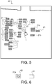
- the Fig. 5 shows the environment 20 with one of that in FIG Fig. 2 Original occupancy shown different later occupancy.
- one of the motor vehicles is no longer parked in the parking lot, so that the corresponding area of the surroundings 20 is now free.
- This motor vehicle is in the Fig. 2 provided with the reference number 21a and the corresponding cells 7 of the occupancy card 30 with the reference number 31a, see Fig. 4 .
- more motor vehicles 21b are now parked in the parking lot, so that compared to the original, in the Fig. 2 Occupancy shown in the area 20 other areas are occupied.
- the autonomous vehicle 1 is shown in addition to the motor vehicles 21, 21b.
- the autonomous vehicle is set up, a sub-area of the surroundings 20 with its sensor 6, in particular while the autonomous vehicle 1 is automatically moving within the surroundings 20.
- the autonomous vehicle 1 is also set up to compare the result of the scanning with the occupancy card 30 in its original occupancy and to detect inconsistencies between the current occupancy of the surroundings 20 and the original occupancy information of the corresponding cells 7 of the occupancy card 30.
- the autonomous vehicle 20 detects a discrepancy between the current occupancy and the original occupancy, since it expects the scanned sub-area to be occupied due to the original occupancy of the surroundings 20, but the corresponding motor vehicle 21 no longer occupies the sub-area.
- the autonomous vehicle 1 is also set up to relate the individual detected discrepancies to one in the Fig. 6 shown first correction allocation card 61 to bundle.
- the first correction occupancy card 61 also comprises a plurality of discrete cells and is assigned to the scanned sub-area.
- the cells of the correction occupancy map 61 each include occupancy information about the current occupancy of the corresponding sub-area of the surroundings 20.
- the cells of the first correction occupancy card 61 are also free and therefore shown in white.
- the Fig. 5 shows the partial occupancy area 62 of the occupancy card 30 assigned to the correction occupancy card 61 in its original occupancy.
- the autonomous vehicle 1 is also set up to update the occupancy map 30 by updating the occupancy information of the cells 7 of the partial occupancy area 62 with the corresponding occupancy information of the cells 7 of the correction occupancy map 61.
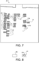
- the Fig. 7 shows an example in which the autonomous vehicle 1 detects one of the newly parked motor vehicles 21b when scanning a further sub-area of the surroundings 20, so that the autonomous vehicle also detects a discrepancy between the current occupancy and the original occupancy card 30. Due to the original occupancy of the surroundings 20, the autonomous vehicle 1 does not expect any occupancy of the further sub-area scanned.
- the autonomous vehicle 1 is also set up to relate the individual detected discrepancies to one in the Fig. 8 second correction allocation card 81 shown.
- the correction occupancy card 81 likewise comprises a plurality of discrete cells and is assigned to the currently scanned sub-area, ie the further sub-area of the complete occupancy card 30.
- the cells of the second correction occupancy map 81 each include occupancy information about the current occupancy of the corresponding sub-area of the surroundings 30.
- the scanned further sub-area is now occupied, the corresponding cells (occupied cells 31b) of the second correction occupancy card 81 are occupied and are therefore shown in black.
- the Fig. 8 shows the partial occupancy area 82 of the occupancy card 30 assigned to the correction occupancy card 81 in its original occupancy.
- the autonomous vehicle 1 is also set up to update the occupancy map 30 by updating the occupancy information of the cells 7 of the partial occupancy area 82 with the corresponding occupancy information of the cells of the second correction occupancy map 81.
- the Fig. 9 shows the occupancy card 30 with its current occupancy.
- the autonomous vehicle 1 is set up to use the occupancy card 30 with its current occupancy.
- the autonomous vehicle 1 is set up in particular to continuously update the occupancy card 30.
- the occupancy card 30 is preferably updated during the automatic movement.
- the occupancy map 30 can also be updated when the autonomous vehicle 1 is stationary.
- the autonomous vehicle 1 is set up in particular to recognize inconsistencies between the current occupancy of the surroundings 20 and the occupancy information of the corresponding cells of the correction occupancy map 61, 81.
- the corresponding correction occupancy card 61, 81 can be deactivated so that the corresponding cells 7 have the occupancy information of the original occupancy.
- the identified discrepancies can be bundled into a further correction occupancy map, the cells of which each contain occupancy information about the current occupancy of corresponding subregions of the surroundings 20.
- the occupancy map can then be updated by updating the occupancy information of the cells of the cells assigned to this sub-area with the corresponding occupancy information of the cells of the further correction occupancy map.
- the autonomous vehicle 1 can also be set up to update the occupancy map by updating the occupancy information of the cells assigned to the sub-area with the corresponding occupancy information of the cells of the correction occupancy map, as soon as a scan of the surroundings with the sensor 6 shows that the correction occupancy map with the current occupancy of the surroundings 20 matches again.
- the autonomous vehicle 1 can also be set up to update the occupancy map 30 by updating the occupancy information of the cells assigned to the sub-area with the corresponding occupancy information of the cells of the correction occupancy map as soon as a scanning of the surroundings 20 with the sensor 6 reveals that part of the correction occupancy map has the current occupancy of the environment 20 again matches.
Landscapes
- Engineering & Computer Science (AREA)
- Radar, Positioning & Navigation (AREA)
- Remote Sensing (AREA)
- Physics & Mathematics (AREA)
- Automation & Control Theory (AREA)
- General Physics & Mathematics (AREA)
- Aviation & Aerospace Engineering (AREA)
- Optics & Photonics (AREA)
- Electromagnetism (AREA)
- Traffic Control Systems (AREA)
- Control Of Position, Course, Altitude, Or Attitude Of Moving Bodies (AREA)
Description
- Die Erfindung betrifft ein Verfahren zum Aktualisieren einer Belegungskarte und ein autonomes Fahrzeug.
- Die
JP 2009 169845 A - Die
US 2008/0009966 A1 zeigt ebenfalls ein Verfahren zur Aktualisierung einer Umgebungskarte bestehend aus Zellen, wobei eine Hinderniskarte relativ zu der Position eines Roboters erzeugt wird und die die Hinderniskarte als neue Umgebungskarte verwendet wird. Die neue Umgebungskarte wird dabei mit der alten Umgebungskarte verglichen und es wird ein Änderungsvektor für jede sich ändernde Zelle definiert, wobei der Änderungsvektor eine Richtung und eine Entfernung des Roboters zu der Zelle aufweist. - Die
EP2 473 890 B2 zeigt ein System zur gleichzeitigen Ortung und Kartierung der Umgebung eines mobilen Roboters. ein Datenerfassungssystem generiert Daten in Form von Zellen, welche die physikalische Umgebung eines mobilen Geräts erfassen. Jeder der Zellen wird eine Wahrscheinlichkeit zugeordnet, ob die Zelle besetzt ist oder leeren Raum beinhaltet. Eine Verarbeitungseinrichtung ermittelt, ob Änderungen in der Besetzungswahrscheinlichkeit einer Zelle anzeigen, dass eine Zelle, die gegenwärtig als leer identifiziert wurde, besetzt worden ist oder eine Zelle, die gegenwärtig als besetzt identifiziert wurde, leer geworden ist und solche Zelle entsprechend markiert, damit diese Zelle im Hinblick auf deren Wahrscheinlichkeit ein Hindernis zu erhalten oder nicht, aktualisiert werden, während sich die besagte Wahrscheinlichkeit ändert. - Die
DE 10 2014 200279 A1 zeigt ein Verfahren zum Detektieren von Objekten in einem Umfeld eines Fahrzeugs, wobei das Umfeld in ein Zellen enthaltendes Belegungsgitter unterteilt ist und den Zellen ein Belegungswert in Abhängigkeit von Kartendaten einer digitalen Karte zugeordnet sind. Stationäre Elemente entsprechen dabei belegten Zellen. Dabei werden die Zellen des Belegungsgitters mit Zellen eines Sensor-Belegungsgitters fusioniert. - Um die Umgebung bzw. das Umfeld zu modellieren, können Belegungskarten (Englisch: occupancy grid maps) verwendet werden. Belegungskarten beschreiben bzw. modellieren das Umfeld in diskreten Zellen, die vorzugsweise quadratisch und insbesondere gitterförmig angeordnet sind. Je nachdem ob der den einzelnen Zellen zugeordnete Bereich des Umfelds durch Objekte belegt oder frei ist, können die entsprechenden Zellen der Belegungskarte als belegt oder frei charakterisiert sein.
- Belegungskarten werden z.B. von autonomen Fahrzeugen verwendet, um automatisch innerhalb des Umfelds zu fahren. Ein autonomes Fahrzeug umfasst einen eigenen Antrieb, um automatisch gesteuert und berührungslos geführt zu werden. Autonome Fahrzeuge sind z.B. fahrerlose Transportfahrzeuge (Englisch: Automated Guided Vehicle (AGV)) oder mobile Roboter.
- Belegungskarten können z.B. durch Umfeldsensorik erstellt werden. Ein gängiges Verfahren ist z.B. das SLAM (Simultanous Localisation And Mapping), das beispielsweise aus der
US 2011/0082585 A1 oder derUS 8,798,840 B2 bekannt ist. - Belegungskarten stellen lediglich eine Momentaufnahme des Umfelds dar. Ändert sich das Umfeld, indem sich die Belegung bestimmter Bereiche ändert, dann beschreiben die einzelnen Zellen der Belegungskarte das aktuelle Umfeld nicht mehr ausreichend.
- Die Aufgabe der Erfindung ist es, eine verbesserte Möglichkeit anzugeben, eine Belegungskarte zu aktualisieren.
- Die Aufgabe der Erfindung wird gelöst durch ein Verfahren zum Aktualisieren einer einem Umfeld zugeordneten Belegungskarte, nach Anspruch 1.
- Ein weiterer Aspekt der Erfindung betrifft ein autonomes Fahrzeug, aufweisend einen Fahrzeuggrundkörper, am Fahrzeuggrundkörper angeordnete Räder, wobei wenigstens einem der Räder ein Antrieb zugeordnet ist, wenigstens einen Sensor, der zum Abtasten des Umfelds, innerhalb dem sich das fahrerlose Transportfahrzeug automatisch bewegen soll, eingerichtet ist, und eine mit dem Sensor und dem Antrieb gekoppelte elektronische Steuervorrichtung, die eingerichtet ist, den Antrieb für ein automatisches Fahren des autonomen Fahrzeugs basierend auf einer Belegungskarte des Umfelds anzusteuern und die eingerichtet ist, das erfindungsgemäße Verfahren durchzuführen. Der Sensor ist vorzugsweise ein Laserscanner, insbesondere ein zweidimensionaler Laserscanner. Der Sensor kann auch eine Kamera oder ein Ultraschallsensor sein.
- Das autonome Fahrzeug ist z.B. ein fahrerloses Transportfahrzeug oder ein mobiler Roboter. Die Belegungskarte ist vorzugsweise im autonomen Fahrzeug, z.B. in dessen elektronischer Steuerungsvorrichtung, gespeichert. Das autonome Fahrzeug ist insbesondere eingerichtet, sich automatisch aufgrund der Belegungskarte innerhalb des Umfelds zu bewegen.
- Erfindungsgemäß wird somit eine Belegungskarte des Umfelds, innerhalb dem sich das Fahrzeug, insbesondere das autonome Fahrzeug bewegen soll, bereitgestellt. Die Belegungskarte umfasst die mehreren diskreten Zellen, welche jeweils eine ursprüngliche Belegungsinformation über die ursprüngliche Belegung entsprechender Bereiche des Umfelds umfassen. Die Belegungskarte mit ihrer ursprünglichen Belegung kann z.B. mittels eines SLAM-Verfahrens erstellt werden.
- Erfindungsgemäß tastet das Fahrzeug, insbesondere das autonome Fahrzeug einen Teilbereich des Umfelds mit seinem Sensor ab. Es können auch mehrere Sensoren vorhanden sein.
- Vorzugsweise erfolgt das diskrete Abtasten des Teilbereichs des Umfelds mit dem Sensor des Fahrzeugs während sich dieses innerhalb des Umfelds bewegt. Das Abtasten des Teilbereichs des Umfelds kann aber alternativ oder zusätzlich auch erfolgend während das Fahrzeug still steht. Das Zusammenfassen von Unstimmigkeiten findet vorzugsweise während der Fahrt statt, um die volle räumliche Ausdehnung der Unstimmigkeit zu erfassen.
- Die vom Sensor erzeugten Signale können z.B. von einer elektronischen Steuervorrichtung des Fahrzeugs bzw. der Steuervorrichtung des autonomen Fahrzeugs ausgewertet werden. Aufgrund der Signale des Sensors bzw. aufgrund des abgetasteten Teilbereichs des Umfelds ist es dem Fahrzeug bzw. dem autonomen Fahrzeug ermöglicht, Unstimmigkeiten zwischen der aktuellen Belegung des Umfelds bzw. dessen Teilbereichs und den ursprünglichen Belegungsinformationen der entsprechenden Zellen der Belegungskarte zu erkennen.
- Eine Unstimmigkeit liegt z.B. vor, wenn diskrete abgetastete Punkte des abgetasteten Teilbereichs des Umfelds frei sind, jedoch aufgrund der Belegungsinformationen der entsprechenden Zellen der Belegungskarte belegt sein sollten. Ein weiteres Beispiel einer Unstimmigkeit ist, wenn diskrete abgetastete Punkte des abgetasteten Teilbereichs des Umfelds belegt sind, jedoch aufgrund der Belegungsinformationen der entsprechenden Zellen der Belegungskarte frei sein sollten.
- Erfindungsgemäß werden anschließend die erkannten Unstimmigkeiten zur Korrekturbelegungskarte gebündelt. Die Korrekturbelegungskarte ist dem abgetasteten Teilbereich zugeordnet und deren Zellen umfassen jeweils eine Belegungsinformation über die aktuelle Belegung des entsprechenden Teilbereichs.
- Anschließend wird die Belegungskarte durch Aktualisieren der Belegungsinformationen der dem Teilbereich zugeordneten Zellen durch die entsprechenden Belegungsinformationen der Zellen der Korrekturbelegungskarte aktualisiert.
- Anschließend wird vorzugsweise die aktualisierte Belegungskarte, d.h. die Belegungskarte mit den aktualisierten Belegungsinformationen zum Bewegen des Fahrzeugs bzw. des autonomen Fahrzeugs verwendet.
- Vorzugsweise wird die Belegungskarte bzw. deren Belegungsinformationen ständig aktualisiert. Dies erfolgt vorzugsweise während sich das Fahrzeug innerhalb des Umfelds bewegt. Das Aktualisieren kann auch erfolgen, wenn das Fahrzeug still steht.
- Ändert sich nach dem Aktualisieren der Belegungskarte diese derart wieder, sodass die Belegungsinformationen der Korrekturbelegungskarte nicht mehr aktuell sind, dann können gemäß einer Ausführungsform des erfindungsgemäßen Verfahrens folgende Verfahrensschritte durchgeführt werden:
- diskretes Abtasten des Teilbereichs des Umfelds mit dem Sensor während sich das Fahrzeug innerhalb des Umfelds bewegt,
- aufgrund des abgetasteten Teilbereichs des Umfelds, Erkennen von Unstimmigkeiten zwischen der aktuellen Belegung des Umfelds und der Belegungsinformationen der entsprechenden Zellen der Korrekturbelegungskarte, und
- Deaktivieren der Korrekturbelegungskarte, sodass die entsprechenden Zellen die ursprünglichen Belegungsinformationen aufweisen.
- Es ist aber auch möglich, dass das erfindungsgemäße Verfahren folgende Verfahrensschritte aufweist:
- diskretes Abtasten des Teilbereichs des Umfelds mit dem Sensor während sich das Fahrzeug innerhalb des Umfelds bewegt,
- aufgrund des abgetasteten Teilbereichs des Umfelds, Erkennen von Unstimmigkeiten zwischen der aktuellen Belegung des Umfelds und der Belegungsinformationen der entsprechenden Zellen der Korrekturbelegungskarte,
- Deaktivieren der Korrekturbelegungskarte,
- Bündeln der erkannten Unstimmigkeiten zu einer weiteren Korrekturbelegungskarte, deren Zellen jeweils eine Belegungsinformation über die aktuelle Belegung des Teilbereiche des Umfelds umfasst, und
- Aktualisieren der Belegungskarte durch Aktualisieren der Belegungsinformationen der Zellen des Teilbereichs durch die entsprechenden Belegungsinformationen der Zellen der weiteren Korrekturbelegungskarte.
- Nach einer bevorzugten Ausführungsform des erfindungsgemäßen Verfahrens kann dieses ein Aktualisieren der Belegungskarte durch Aktualisieren der Belegungsinformationen der dem Teilbereich zugeordneten Zellen durch die entsprechenden Belegungsinformationen der Zellen der Korrekturbelegungskarte aufweisen, sobald ein Abtasten des Umfelds mit dem Sensor ergibt, dass die Korrekturbelegungskarte mit der aktuellen Belegung des Umfelds wieder übereinstimmt.
- Nach einer weiteren Variante des erfindungsgemäßen Verfahren kann dieses auch ein Aktualisieren der Belegungskarte durch Aktualisieren der Belegungsinformationen der dem Teilbereich zugeordneten Zellen durch die entsprechenden Belegungsinformationen der Zellen der Korrekturbelegungskarte aufweisen, sobald ein Abtasten des Umfelds mit dem Sensor ergibt, dass ein Teil der Korrekturbelegungskarte mit der aktuellen Belegung des Umfelds wieder übereinstimmt.
- Ein Ausführungsbeispiel der Erfindung ist exemplarisch in den beigefügten schematischen Figuren dargestellt. Es zeigen:
- Fig. 1
- ein autonomes Fahrzeug,
- Fig. 2
- eine Draufsicht eines Umfelds mit einer ursprünglichen Belegung,
- Fig. 3
- eine mehrere diskrete Zellen aufweisende Belegungskarte für das Umfeld,
- Fig. 4
- die Belegungskarte, die die Belegung des Umfelds der
Fig. 2 darstellt, - Fig. 5
- eine Draufsicht des Umfelds, in dem sich das autonome Fahrzeug bewegt und das eine von der Belegung der
Fig. 2 unterschiedliche Belegung aufweist, - Fig. 6
- eine erste Korrekturbelegungskarte,
- Fig. 7
- eine weitere Draufsicht des Umfelds, in dem sich das autonome Fahrzeug bewegt und das eine von der Belegung der
Fig. 2 unterschiedliche Belegung aufweist, - Fig. 8
- eine zweite Korrekturbelegungskarte, und
- Fig. 9
- die Belegungskarte, die die Belegung des Umfelds der
Figuren 5 und7 darstellt. - Die
Fig. 1 zeigt eine Draufsicht eines autonomen Fahrzeugs 1 in einer schematischen Darstellung. Das autonome Fahrzeug 1 ist z.B. ein fahrerloses Transportfahrzeug oder ein mobiler Roboter. - Im Falle des vorliegenden Ausführungsbeispiels umfasst das autonome Fahrzeug 1 einen Fahrzeuggrundkörper 2 und mehrere Räder 3, welche am Fahrzeuggrundkörper 2 mittels nicht näher dargestellten Aufhängungen befestigt sind.
- Des Weiteren umfasst im Falle des vorliegenden Ausführungsbeispiels das autonome Fahrzeug 1 Antriebe 4. Jedem der Räder 3 ist einer der Antriebe 4 zugeordnet. Die Antriebe 4 sind insbesondere elektrische Antriebe, vorzugsweise geregelte elektrische Antriebe.
- Das autonome Fahrzeug 1 weist eine z.B. am Fahrzeuggrundkörper 2 angeordnete elektronische Steuervorrichtung 5 auf, die mit den Antrieben 4 verbunden ist, um diese für eine automatische Bewegung des autonomen Fahrzeugs 1 anzusteuern. Dazu läuft z.B. auf der elektronischen Steuervorrichtung 5 ein geeignetes Rechnerprogramm.
- Das autonome Fahrzeug 1 umfasst wenigstens einen mit der elektronischen Steuervorrichtung 5 verbundenen Sensor 6, der zum Abtasten der Umgebung bzw. des Umfelds des autonomen Fahrzeugs 1 eingerichtet ist. Der Sensor 6 ist vorzugsweise ein Laserscanner, insbesondere ein zweidimensionaler Laserscanner. Der Sensor kann auch eine Kamera oder ein Ultraschallsensor sein.
- Das autonome Fahrzeug 1 ist insbesondere vorgesehen, sich automatisch innerhalb eines in der
Fig. 2 gezeigten Umfelds 20 zu bewegen. Dazu ist im Falle des vorliegenden Ausführungsbeispiels eine in derFigur 3 gezeigte Belegungskarte 30 vorgesehen, welche dem Umfeld 20 zugeordnet und mehrere diskrete Zellen 7 aufweist, welche jeweils eine Belegungsinformation über die Belegung entsprechender Bereiche des Umfelds 20 umfassen. Die Belegungskarte 30 ist z.B. in einem Speicher der elektronischen Steuervorrichtung 5 gespeichert. - Im Falle des vorliegenden Ausführungsbeispiels handelt es sich bei dem Umfeld 20 um einen Parkplatz, sodass Bereiche des Umfelds 20 bzw. des Parkplatzes mit Kraftfahrzeugen 21 belegt oder frei sein können.
- In der
Fig. 2 ist das Umfeld 20 mit seiner ursprünglichen Belegung gezeigt. DieFig. 4 zeigt die Belegung der Belegungskarte 30 mit einer ursprünglichen Belegung der Zellen 7 entsprechend der Belegung des Umfelds 20 wie in derFig. 2 dargestellt. Sind Zellen 7 der Belegungskarte 30 belegt (belegte Zellen 31), so sind diese schwarz dargestellt, freie Zellen dagegen weiß. Die belegten Zellen 31 sind im Falle des vorliegenden Ausführungsbeispiels den Umrissen der Kraftfahrzeuge 21 zugeordnet. Die Belegungskarte 30 mit ihrer ursprünglichen Belegung wurde z.B. mit einem SLAM-Verfahren hergestellt. Es ist auch möglich, dass Teile des Umfelds 20 noch nicht abgetastet wurden, sodass die entsprechenden Zellen 7 weder als belegt noch als frei eingeteilt sind. - Die Belegung des Umfelds 20 ist in der Regel nicht zeitlich konstant, da z.B. Kraftfahrzeuge 21 den Parkplatz verlassen oder zusätzlich Kraftfahrzeuge 21b auf dem Parkplatz parken.
- Die
Fig. 5 zeigt das Umfeld 20 mit einer von der in derFig. 2 gezeigten ursprünglichen Belegung unterschiedlichen späteren Belegung. - Im Falle des vorliegenden Ausführungsbeispiels parkt eines der Kraftfahrzeuge nicht mehr auf dem Parkplatz, sodass der entsprechende Bereich des Umfelds 20 nun frei ist. Dieses Kraftfahrzeug ist in der
Fig. 2 mit dem Bezugszeichen 21a versehen und die entsprechenden Zellen 7 der Belegungskarte 30 mit dem Bezugszeichen 31a, sieheFig. 4 . Außerdem parken nun weitere Kraftfahrzeuge 21b auf dem Parkplatz, sodass nun im Vergleich zur ursprünglichen, in derFig. 2 gezeigten Belegung des Umfelds 20 weitere Bereiche belegt sind. - In der
Fig. 5 ist zusätzlich zu den Kraftfahrzeugen 21, 21b das autonome Fahrzeug 1 gezeigt. - Im Falle des vorliegenden Ausführungsbeispiels ist das autonome Fahrzeug eingerichtet, einen Teilbereich des Umfelds 20 mit seinem Sensor 6 abzutasten, insbesondere während sich das autonome Fahrzeugs 1 automatisch innerhalb des Umfelds 20 bewegt.
- Das autonome Fahrzeug 1 ist im Falle des vorliegenden Ausführungsbeispiels ferner eingerichtet, das Ergebnis des Abtastens mit der Belegungskarte 30 in ihrer ursprünglichen Belegung zu vergleichen und Unstimmigkeiten zwischen der aktuellen Belegung des Umfelds 20 und der ursprünglichen Belegungsinformation der entsprechenden Zellen 7 der Belegungskarte 30 zu erkennen.
- In dem in de
Fig. 5 gezeigten Beispiels erkennt das autonome Fahrzeug 20 eine Unstimmigkeit zwischen der aktuellen Belegung und der ursprünglichen Belegung, da es aufgrund der ursprünglichen Belegung des Umfelds 20 eine Belegung des abgetasteten Teilbereichs erwartet, das entsprechende Kraftfahrzeug 21 jedoch nicht mehr den Teilbereich belegt. - Das autonome Fahrzeug 1 ist im Falle des vorliegenden Ausführungsbeispiels ferner eingerichtet, die einzelnen erkannten Unstimmigkeiten zu einer in der
Fig. 6 gezeigten ersten Korrekturbelegungskarte 61 zu bündeln. Die erste Korrekturbelegungskarte 61 umfasst ebenfalls mehrere diskrete Zellen und ist dem abgetasteten Teilbereich zugeordnet. Die Zellen der Korrekturbelegungskarte 61 umfassen jeweils eine Belegungsinformation über die aktuelle Belegung des entsprechenden Teilbereichs des Umfelds 20. - Da in dem in der
Fig. 5 gezeigten Beispiel der abgetastete Teilbereich frei ist, sind die Zellen der ersten Korrekturbelegungskarte 61 ebenfalls frei und deshalb weiß dargestellt. - Die
Fig. 5 zeigt noch den der Korrekturbelegungskarte 61 zugeordnete Teilbelegungsbereich 62 der Belegungskarte 30 in ihrer ursprünglichen Belegung. - Das autonome Fahrzeug 1 ist im Falle des vorliegenden Ausführungsbeispiels ferner eingerichtet, die Belegungskarte 30 durch Aktualisieren der Belegungsinformationen der Zellen 7 des Teilbelegungsbereichs 62 durch die entsprechenden Belegungsinformationen der Zellen 7 der Korrekturbelegungskarte 61 zu aktualisieren.
- Die
Fig. 7 zeigt ein Beispiel, bei dem das autonome Fahrzeug 1 beim Abtasten eines weiteren Teilbereichs des Umfelds 20 eines der neu parkenden Kraftfahrzeuge 21b erkennt, sodass das autonome Fahrzeug ebenfalls eine Unstimmigkeit zwischen der aktuellen Belegung und der ursprünglichen Belegungskarte 30 erkennt. Aufgrund der ursprünglichen Belegung des Umfelds 20 erwartet das autonome Fahrzeug 1 keine Belegung des abgetasteten weiteren Teilbereichs. - Das autonome Fahrzeug 1 ist im Falle des vorliegenden Ausführungsbeispiels ferner eingerichtet, die einzelnen erkannten Unstimmigkeiten zu einer in der
Fig. 8 gezeigten zweiten Korrekturbelegungskarte 81 zu bündeln. Die Korrekturbelegungskarte 81 umfasst ebenfalls mehrere diskrete Zellen und ist dem aktuell abgetasteten Teilbereich, d.h. dem weiteren Teilbereich der kompletten Belegungskarte 30 zugeordnet. Die Zellen der zweiten Korrekturbelegungskarte 81 umfassen jeweils eine Belegungsinformation über die aktuelle Belegung des entsprechenden Teilbereichs des Umfelds 30. - Da in dem in der
Fig. 7 gezeigten Beispiel der abgetastete weitere Teilbereich nun belegt ist, sind die entsprechenden Zellen (belegte Zellen 31b) der zweiten Korrekturbelegungskarte 81 belegt und deshalb schwarz dargestellt. - Die
Fig. 8 zeigt noch den der Korrekturbelegungskarte 81 zugeordnete Teilbelegungsbereich 82 der Belegungskarte 30 in ihrer ursprünglichen Belegung. - Das autonome Fahrzeug 1 ist im Falle des vorliegenden Ausführungsbeispiels ferner eingerichtet, die Belegungskarte 30 durch Aktualisieren der Belegungsinformationen der Zellen 7 des Teilbelegungsbereichs 82 durch die entsprechenden Belegungsinformationen der Zellen der zweiten Korrekturbelegungskarte 81 zu aktualisieren.
- Die
Fig. 9 zeigt die Belegungskarte 30 mit ihrer aktuellen Belegung. - Das autonome Fahrzeug 1 ist im Falle des vorliegenden Ausführungsbeispiels eingerichtet, die Belegungskarte 30 mit ihrer aktuellen Belegung zu verwenden.
- Das autonome Fahrzeug 1 ist insbesondere eingerichtet, die Belegungskarte 30 kontinuierlich zu aktualisieren. Die Belegungskarte 30 wird vorzugsweise während des automatischen Bewegens aktualisiert. Die Belegungskarte 30 kann auch im Stillstand des autonomen Fahrzeugs 1 aktualisiert werden.
- Das autonome Fahrzeug 1 ist insbesondere eingerichtet, Unstimmigkeiten zwischen der aktuellen Belegung des Umfelds 20 und der Belegungsinformation der entsprechenden Zellen der Korrekturbelegungskarte 61, 81 zu erkennen.
- Wird eine solche Unstimmigkeit erkannt, dann kann die entsprechende Korrekturbelegungskarte 61, 81 deaktiviert werden, sodass die entsprechenden Zellen 7 die Belegungsinformationen der ursprünglichen Belegung aufweisen.
- Es ist aber auch möglich, dass die erkannten Unstimmigkeiten zu einer weiteren Korrekturbelegungskarte gebündelt werden, deren Zellen jeweils eine Belegungsinformation über die aktuelle Belegung entsprechender Teilbereiche des Umfelds 20 umfasst. Danach kann die Belegungskarte durch Aktualisieren der Belegungsinformationen der Zellen diesen Teilbereich zugeordneten Zellen durch die entsprechenden Belegungsinformationen der Zellen der weiteren Korrekturbelegungskarte aktualisiert werden.
- Das autonome Fahrzeug 1 kann auch eingerichtet sein, die Belegungskarte durch Aktualisieren der Belegungsinformationen dem Teilbereich zugeordnete Zellen durch die entsprechenden Belegungsinformationen der Zellen der Korrekturbelegungskarte zu aktualisieren, sobald ein Abtasten des Umfelds mit dem Sensor 6 ergibt, dass die Korrekturbelegungskarte mit der aktuellen Belegung des Umfelds 20 wieder übereinstimmt.
- Das autonome Fahrzeug 1 kann auch eingerichtet sein, die Belegungskarte 30 durch Aktualisieren der Belegungsinformationen der dem Teilbereich zugeordneten Zellen durch die entsprechenden Belegungsinformationen der Zellen der Korrekturbelegungskarte zu aktualisieren, sobald ein Abtasten des Umfelds 20 mit dem Sensor 6 ergibt, dass ein Teil der Korrekturbelegungskarte mit der aktuellen Belegung des Umfelds 20 wieder übereinstimmt.
Claims (5)
- Verfahren zum Aktualisieren einer einem Umfeld (20) zugeordneten Belegungskarte (30), aufweisend folgende Verfahrensschritte:- Bereitstellen einer Belegungskarte (30) mit mehreren diskreten Zellen (7), welche jeweils eine ursprüngliche Belegungsinformation über die ursprüngliche Belegung entsprechender Bereiche des Umfelds (20) umfassen,- diskretes Abtasten eines Teilbereichs des Umfelds (20) mit einem Sensor (6) eines Fahrzeugs (1),- aufgrund des abgetasteten Teilbereichs des Umfelds (20), Erkennen von Unstimmigkeiten zwischen der aktuellen Belegung des Teilbereichs und der ursprünglichen Belegungsinformationen der entsprechenden Zellen (7) der Belegungskarte (30),- Bündeln der erkannten Unstimmigkeiten zu einer Korrekturbelegungskarte (61, 81), die dem abgetasteten Teilbereich des Umfelds (20) zugeordnet ist und deren Zellen jeweils eine Belegungsinformation über die aktuelle Belegung des Teilbereichs umfassen, und- Aktualisieren der Belegungskarte (30) durch Aktualisieren der Belegungsinformationen der dem Teilbereich zugeordneten Zellen (7) durch die entsprechenden Belegungsinformationen der Zellen der Korrekturbelegungskarte (61, 81),gekennzeichnet durch folgende weitere Verfahrensschritte:- diskretes Abtasten des Teilbereichs des Umfelds (20) mit dem Sensor (6) während sich das Fahrzeug (1) innerhalb des Umfelds (20) bewegt,- aufgrund des abgetasteten Teilbereichs (61, 81) des Umfelds (20), Erkennen von Unstimmigkeiten zwischen der aktuellen Belegung des Umfelds (20) und der Belegungsinformation der entsprechenden Zellen (7) der Korrekturbelegungskarte (61, 81), und- Deaktivieren der Korrekturbelegungskarte (61, 81),- Bündeln der erkannten Unstimmigkeiten zu einer weiteren Korrekturbelegungskarte, deren Zellen (7) jeweils eine Belegungsinformation über die aktuelle Belegung entsprechender Bereiche des Umfelds (20) umfasst, und- Aktualisieren der Belegungskarte (30) durch Aktualisieren der Belegungsinformationen der dem weiteren Teilbereich zugeordneten Zellen (7) durch die entsprechenden Belegungsinformationen der Zellen (7) der weiteren Korrekturbelegungskarte.
- Verfahren nach Anspruch 1, aufweisend: Aktualisieren der Belegungskarte (30) durch Aktualisieren der Belegungsinformationen der dem Teilbereich zugeordneten Zellen (7) durch die entsprechenden Belegungsinformationen der Zellen (7) der Korrekturbelegungskarte (61, 81), sobald ein Abtasten des Umfelds (20) mit dem Sensor (6) ergibt, dass die Korrekturbelegungskarte (61, 81) mit der aktuellen Belegung des Umfelds (20) wieder übereinstimmt.
- Verfahren nach Anspruch 1, aufweisend: Aktualisieren der Belegungskarte (30) durch Aktualisieren der Belegungsinformationen der dem Teilbereich zugeordneten Zellen (7) durch die entsprechenden Belegungsinformationen der Zellen (7) der Korrekturbelegungskarte (61, 81), sobald ein Abtasten des Umfelds (20) mit dem Sensor (6) ergibt, dass ein Teil der Korrekturbelegungskarte (30) mit der aktuellen Belegung des Umfelds (20) wieder übereinstimmt.
- Verfahren nach einem der Ansprüche 1 bis 3, wobei der Sensor (6) ein Laserscanner, insbesondere ein zweidimensionaler Sensor ist.
- Autonomes Fahrzeug, aufweisend einen Fahrzeuggrundkörper (2), am Fahrzeuggrundkörper (2) angeordnete Räder, von denen wenigstens einem der Räder (3) ein Antrieb (4) zugeordnet ist, wenigstens einen Sensor (6), der zum Abtasten des Umfelds (20), innerhalb sich das fahrerlose Transportfahrzeug automatisch bewegen soll, eingerichtet ist, und eine mit dem Sensor (6) und dem Antrieb (4) gekoppelte elektronische Steuervorrichtung (5), die eingerichtet ist, den Antrieb (4) für ein automatisches Bewegen des autonomen Fahrzeugs (1) basierend auf einer Belegungskarte (3) des Umfelds (20) anzusteuern und die eingerichtet ist, das Verfahren nach einem der Ansprüche 1 bis 4 durchzuführen.
Applications Claiming Priority (2)
| Application Number | Priority Date | Filing Date | Title |
|---|---|---|---|
| DE102016203547.9A DE102016203547A1 (de) | 2016-03-03 | 2016-03-03 | Verfahren zum Aktualisieren einer Belegungskarte und autonomes Fahrzeug |
| PCT/EP2017/053843 WO2017148730A1 (de) | 2016-03-03 | 2017-02-21 | Verfahren zum aktualisieren einer belegungskarte und autonomes fahrzeug |
Publications (2)
| Publication Number | Publication Date |
|---|---|
| EP3423911A1 EP3423911A1 (de) | 2019-01-09 |
| EP3423911B1 true EP3423911B1 (de) | 2021-01-20 |
Family
ID=58108597
Family Applications (1)
| Application Number | Title | Priority Date | Filing Date |
|---|---|---|---|
| EP17706721.2A Active EP3423911B1 (de) | 2016-03-03 | 2017-02-21 | Verfahren zum aktualisieren einer belegungskarte und autonomes fahrzeug |
Country Status (3)
| Country | Link |
|---|---|
| EP (1) | EP3423911B1 (de) |
| DE (1) | DE102016203547A1 (de) |
| WO (1) | WO2017148730A1 (de) |
Cited By (1)
| Publication number | Priority date | Publication date | Assignee | Title |
|---|---|---|---|---|
| DE102024002676A1 (de) | 2024-08-17 | 2026-02-19 | Mercedes-Benz Group AG | Computerimplementiertes Verfahren zur Bewertung der Güte von Belegungsprädiktionsmodellen, Trainingsverfahren für Belegungsprädiktionsmodelle, Verfahren zum Betrieb eines Fahrzeugs sowie Fahrzeug |
Families Citing this family (1)
| Publication number | Priority date | Publication date | Assignee | Title |
|---|---|---|---|---|
| DE202018102171U1 (de) * | 2018-04-19 | 2019-07-22 | Kuka Deutschland Gmbh | Sensorhalter und Vorrichtung mit einem solchen Sensorhalter |
Citations (4)
| Publication number | Priority date | Publication date | Assignee | Title |
|---|---|---|---|---|
| US20080009966A1 (en) * | 2006-07-05 | 2008-01-10 | Battelle Energy Alliance, Llc | Occupancy Change Detection System and Method |
| JP2009169845A (ja) * | 2008-01-18 | 2009-07-30 | Toyota Motor Corp | 自律移動ロボット及び地図更新方法 |
| EP2473890A2 (de) * | 2009-08-31 | 2012-07-11 | Neato Robotics, Inc. | Verfahren und vorrichtung zur simultanen ortung und kartierung (slam) der umgebung eines mobilen roboters |
| DE102014200279A1 (de) * | 2014-01-10 | 2015-07-16 | Robert Bosch Gmbh | Verfahren und Vorrichtung zum Detektieren von Objekten in einem Umfeld eines Fahrzeugs |
Family Cites Families (3)
| Publication number | Priority date | Publication date | Assignee | Title |
|---|---|---|---|---|
| US8798840B2 (en) | 2011-09-30 | 2014-08-05 | Irobot Corporation | Adaptive mapping with spatial summaries of sensor data |
| DE102012207269A1 (de) * | 2012-05-02 | 2013-11-07 | Kuka Laboratories Gmbh | Fahrerloses Transportfahrzeug und Verfahren zum Betreiben eines fahrerlosen Transportfahrzeugs |
| DE102013211109A1 (de) * | 2013-06-14 | 2014-12-31 | Robert Bosch Gmbh | Assistenzvorrichtung und Verfahren zum Unterstützen eines Fahrers des Fahrzeugs |
-
2016
- 2016-03-03 DE DE102016203547.9A patent/DE102016203547A1/de not_active Ceased
-
2017
- 2017-02-21 WO PCT/EP2017/053843 patent/WO2017148730A1/de not_active Ceased
- 2017-02-21 EP EP17706721.2A patent/EP3423911B1/de active Active
Patent Citations (4)
| Publication number | Priority date | Publication date | Assignee | Title |
|---|---|---|---|---|
| US20080009966A1 (en) * | 2006-07-05 | 2008-01-10 | Battelle Energy Alliance, Llc | Occupancy Change Detection System and Method |
| JP2009169845A (ja) * | 2008-01-18 | 2009-07-30 | Toyota Motor Corp | 自律移動ロボット及び地図更新方法 |
| EP2473890A2 (de) * | 2009-08-31 | 2012-07-11 | Neato Robotics, Inc. | Verfahren und vorrichtung zur simultanen ortung und kartierung (slam) der umgebung eines mobilen roboters |
| DE102014200279A1 (de) * | 2014-01-10 | 2015-07-16 | Robert Bosch Gmbh | Verfahren und Vorrichtung zum Detektieren von Objekten in einem Umfeld eines Fahrzeugs |
Cited By (1)
| Publication number | Priority date | Publication date | Assignee | Title |
|---|---|---|---|---|
| DE102024002676A1 (de) | 2024-08-17 | 2026-02-19 | Mercedes-Benz Group AG | Computerimplementiertes Verfahren zur Bewertung der Güte von Belegungsprädiktionsmodellen, Trainingsverfahren für Belegungsprädiktionsmodelle, Verfahren zum Betrieb eines Fahrzeugs sowie Fahrzeug |
Also Published As
| Publication number | Publication date |
|---|---|
| DE102016203547A1 (de) | 2017-09-07 |
| WO2017148730A1 (de) | 2017-09-08 |
| EP3423911A1 (de) | 2019-01-09 |
Similar Documents
| Publication | Publication Date | Title |
|---|---|---|
| EP2981951B1 (de) | Automatisches befahren einer strecke | |
| EP3482622B1 (de) | Verfahren zur automatischen führung eines fahrzeugs entlang eines virtuellen schienensystems | |
| DE102014111125B4 (de) | Verfahren zum Erkennen eines Objekts in einem Umgebungsbereich eines Kraftfahrzeugs mittels eines Ultraschallsensors, Fahrerassistenzsystem sowie Kraftfahrzeug | |
| DE102015203016B4 (de) | Verfahren und Vorrichtung zur optischen Selbstlokalisation eines Kraftfahrzeugs in einem Umfeld | |
| EP2943910A1 (de) | Erstellung einer hinderniskarte | |
| EP3454084B1 (de) | Verfahren zum betreiben eines fahrerassistenzsystems für ein kraftfahrzeug unter verwendung einer vektorbasierten und einer gitterbasierten umgebungskarte sowie fahrerassistenzsystem | |
| DE102014111126A1 (de) | Verfahren zum Erzeugen einer Umgebungskarte eines Umgebungsbereichs eines Kraftfahrzeugs, Fahrerassistenzsystem sowie Kraftfahrzeug | |
| DE102017208385A1 (de) | Verfahren zum Unterstützen eines Einparkvorgangs eines Kraftfahrzeugs, elektronisches Einparkhilfesystem sowie Kraftfahrzeug | |
| DE102016224212A1 (de) | Automatisierte Freiraumerkennung mittels Differenzanalyse für Fahrzeuge | |
| DE102016102065A1 (de) | Verfahren zum Unterstützen einer autonomen Fahrt eines Kraftfahrzeugs, Steuereinrichtung sowie Parkassistenzsystem | |
| EP3655936A1 (de) | Verfahren und system zum detektieren eines freien bereiches innerhalb eines parkplatzes | |
| DE102020107941A1 (de) | Verfahren zum Bereitstellen von unterschiedlichen Fahrerassistenzfunktionen für ein Fahrzeug zum automatisierten Abfahren von zuvor aufgezeichneten Wegstrecken, Recheneinrichtung sowie Fahrerassistenzvorrichtung | |
| DE102021001282A1 (de) | Mobiles System und Verfahren zum Betreiben eines mobilen Systems | |
| DE102016223072B4 (de) | Bestimmen einer Eigenbewegung eines Fahrzeugs anhand von ortsfesten Objekten | |
| DE102022202739A1 (de) | Verfahren zum Lokalisieren eines Kraftfahrzeugs | |
| DE102016203547A1 (de) | Verfahren zum Aktualisieren einer Belegungskarte und autonomes Fahrzeug | |
| DE102018104963A1 (de) | Verfahren zum Unterstützen eines Benutzers eines Kraftfahrzeugs beim Einparken auf einem Parkplatz, entsprechendes Computerprogrammprodukt, Unterstützungssystem und Kraftfahrzeug | |
| DE102019128253B4 (de) | Verfahren zum Navigieren eines Flurförderzeugs | |
| DE102018003086A1 (de) | Verfahren zum automatischen Anfahren eines Parkplatzes | |
| WO2018172240A1 (de) | Verfahren und auswertevorrichtung zum erfassen einer umgebung eines fahrzeugs und fahrzeug | |
| DE102018210361B4 (de) | Verfahren zum Ermitteln einer Relativpose zwischen einem Fahrzeug und einem Zielobjekt | |
| DE102022208059B3 (de) | Verfahren zum Ermitteln einer eine Parklücke beschreibenden Umfeldinformation mithilfe eines faltenden neuronalen Netzes | |
| DE102023202394A1 (de) | Verfahren und eine Vorrichtung zur Umfeldmodellierung | |
| WO2022135930A1 (de) | Verfahren zum bestimmen eines freiraums in einer fahrzeugumgebung | |
| DE102016111878A1 (de) | Verfahren zum Bestimmen einer Ausrichtung eines auf einer Parkfläche geparkten Kraftfahrzeugs, Steuergerät, Fahrerassistenzsystem sowie Kraftfahrzeug |
Legal Events
| Date | Code | Title | Description |
|---|---|---|---|
| STAA | Information on the status of an ep patent application or granted ep patent |
Free format text: STATUS: UNKNOWN |
|
| STAA | Information on the status of an ep patent application or granted ep patent |
Free format text: STATUS: THE INTERNATIONAL PUBLICATION HAS BEEN MADE |
|
| PUAI | Public reference made under article 153(3) epc to a published international application that has entered the european phase |
Free format text: ORIGINAL CODE: 0009012 |
|
| STAA | Information on the status of an ep patent application or granted ep patent |
Free format text: STATUS: REQUEST FOR EXAMINATION WAS MADE |
|
| 17P | Request for examination filed |
Effective date: 20180921 |
|
| AK | Designated contracting states |
Kind code of ref document: A1 Designated state(s): AL AT BE BG CH CY CZ DE DK EE ES FI FR GB GR HR HU IE IS IT LI LT LU LV MC MK MT NL NO PL PT RO RS SE SI SK SM TR |
|
| AX | Request for extension of the european patent |
Extension state: BA ME |
|
| DAV | Request for validation of the european patent (deleted) | ||
| DAX | Request for extension of the european patent (deleted) | ||
| GRAP | Despatch of communication of intention to grant a patent |
Free format text: ORIGINAL CODE: EPIDOSNIGR1 |
|
| STAA | Information on the status of an ep patent application or granted ep patent |
Free format text: STATUS: GRANT OF PATENT IS INTENDED |
|
| INTG | Intention to grant announced |
Effective date: 20200911 |
|
| GRAS | Grant fee paid |
Free format text: ORIGINAL CODE: EPIDOSNIGR3 |
|
| GRAA | (expected) grant |
Free format text: ORIGINAL CODE: 0009210 |
|
| STAA | Information on the status of an ep patent application or granted ep patent |
Free format text: STATUS: THE PATENT HAS BEEN GRANTED |
|
| AK | Designated contracting states |
Kind code of ref document: B1 Designated state(s): AL AT BE BG CH CY CZ DE DK EE ES FI FR GB GR HR HU IE IS IT LI LT LU LV MC MK MT NL NO PL PT RO RS SE SI SK SM TR |
|
| REG | Reference to a national code |
Ref country code: GB Ref legal event code: FG4D Free format text: NOT ENGLISH |
|
| REG | Reference to a national code |
Ref country code: CH Ref legal event code: EP |
|
| REG | Reference to a national code |
Ref country code: DE Ref legal event code: R096 Ref document number: 502017009116 Country of ref document: DE |
|
| REG | Reference to a national code |
Ref country code: AT Ref legal event code: REF Ref document number: 1356965 Country of ref document: AT Kind code of ref document: T Effective date: 20210215 |
|
| REG | Reference to a national code |
Ref country code: IE Ref legal event code: FG4D Free format text: LANGUAGE OF EP DOCUMENT: GERMAN |
|
| REG | Reference to a national code |
Ref country code: NL Ref legal event code: MP Effective date: 20210120 |
|
| REG | Reference to a national code |
Ref country code: LT Ref legal event code: MG9D |
|
| PG25 | Lapsed in a contracting state [announced via postgrant information from national office to epo] |
Ref country code: LT Free format text: LAPSE BECAUSE OF FAILURE TO SUBMIT A TRANSLATION OF THE DESCRIPTION OR TO PAY THE FEE WITHIN THE PRESCRIBED TIME-LIMIT Effective date: 20210120 Ref country code: BG Free format text: LAPSE BECAUSE OF FAILURE TO SUBMIT A TRANSLATION OF THE DESCRIPTION OR TO PAY THE FEE WITHIN THE PRESCRIBED TIME-LIMIT Effective date: 20210420 Ref country code: FI Free format text: LAPSE BECAUSE OF FAILURE TO SUBMIT A TRANSLATION OF THE DESCRIPTION OR TO PAY THE FEE WITHIN THE PRESCRIBED TIME-LIMIT Effective date: 20210120 Ref country code: HR Free format text: LAPSE BECAUSE OF FAILURE TO SUBMIT A TRANSLATION OF THE DESCRIPTION OR TO PAY THE FEE WITHIN THE PRESCRIBED TIME-LIMIT Effective date: 20210120 Ref country code: GR Free format text: LAPSE BECAUSE OF FAILURE TO SUBMIT A TRANSLATION OF THE DESCRIPTION OR TO PAY THE FEE WITHIN THE PRESCRIBED TIME-LIMIT Effective date: 20210421 Ref country code: NO Free format text: LAPSE BECAUSE OF FAILURE TO SUBMIT A TRANSLATION OF THE DESCRIPTION OR TO PAY THE FEE WITHIN THE PRESCRIBED TIME-LIMIT Effective date: 20210420 Ref country code: PT Free format text: LAPSE BECAUSE OF FAILURE TO SUBMIT A TRANSLATION OF THE DESCRIPTION OR TO PAY THE FEE WITHIN THE PRESCRIBED TIME-LIMIT Effective date: 20210520 |
|
| PG25 | Lapsed in a contracting state [announced via postgrant information from national office to epo] |
Ref country code: PL Free format text: LAPSE BECAUSE OF FAILURE TO SUBMIT A TRANSLATION OF THE DESCRIPTION OR TO PAY THE FEE WITHIN THE PRESCRIBED TIME-LIMIT Effective date: 20210120 Ref country code: RS Free format text: LAPSE BECAUSE OF FAILURE TO SUBMIT A TRANSLATION OF THE DESCRIPTION OR TO PAY THE FEE WITHIN THE PRESCRIBED TIME-LIMIT Effective date: 20210120 Ref country code: LV Free format text: LAPSE BECAUSE OF FAILURE TO SUBMIT A TRANSLATION OF THE DESCRIPTION OR TO PAY THE FEE WITHIN THE PRESCRIBED TIME-LIMIT Effective date: 20210120 Ref country code: SE Free format text: LAPSE BECAUSE OF FAILURE TO SUBMIT A TRANSLATION OF THE DESCRIPTION OR TO PAY THE FEE WITHIN THE PRESCRIBED TIME-LIMIT Effective date: 20210120 |
|
| PG25 | Lapsed in a contracting state [announced via postgrant information from national office to epo] |
Ref country code: IS Free format text: LAPSE BECAUSE OF FAILURE TO SUBMIT A TRANSLATION OF THE DESCRIPTION OR TO PAY THE FEE WITHIN THE PRESCRIBED TIME-LIMIT Effective date: 20210520 |
|
| REG | Reference to a national code |
Ref country code: DE Ref legal event code: R097 Ref document number: 502017009116 Country of ref document: DE |
|
| REG | Reference to a national code |
Ref country code: BE Ref legal event code: MM Effective date: 20210228 |
|
| PG25 | Lapsed in a contracting state [announced via postgrant information from national office to epo] |
Ref country code: EE Free format text: LAPSE BECAUSE OF FAILURE TO SUBMIT A TRANSLATION OF THE DESCRIPTION OR TO PAY THE FEE WITHIN THE PRESCRIBED TIME-LIMIT Effective date: 20210120 Ref country code: CZ Free format text: LAPSE BECAUSE OF FAILURE TO SUBMIT A TRANSLATION OF THE DESCRIPTION OR TO PAY THE FEE WITHIN THE PRESCRIBED TIME-LIMIT Effective date: 20210120 Ref country code: MC Free format text: LAPSE BECAUSE OF FAILURE TO SUBMIT A TRANSLATION OF THE DESCRIPTION OR TO PAY THE FEE WITHIN THE PRESCRIBED TIME-LIMIT Effective date: 20210120 Ref country code: LU Free format text: LAPSE BECAUSE OF NON-PAYMENT OF DUE FEES Effective date: 20210221 Ref country code: SM Free format text: LAPSE BECAUSE OF FAILURE TO SUBMIT A TRANSLATION OF THE DESCRIPTION OR TO PAY THE FEE WITHIN THE PRESCRIBED TIME-LIMIT Effective date: 20210120 |
|
| PLBE | No opposition filed within time limit |
Free format text: ORIGINAL CODE: 0009261 |
|
| STAA | Information on the status of an ep patent application or granted ep patent |
Free format text: STATUS: NO OPPOSITION FILED WITHIN TIME LIMIT |
|
| PG25 | Lapsed in a contracting state [announced via postgrant information from national office to epo] |
Ref country code: RO Free format text: LAPSE BECAUSE OF FAILURE TO SUBMIT A TRANSLATION OF THE DESCRIPTION OR TO PAY THE FEE WITHIN THE PRESCRIBED TIME-LIMIT Effective date: 20210120 Ref country code: SK Free format text: LAPSE BECAUSE OF FAILURE TO SUBMIT A TRANSLATION OF THE DESCRIPTION OR TO PAY THE FEE WITHIN THE PRESCRIBED TIME-LIMIT Effective date: 20210120 Ref country code: DK Free format text: LAPSE BECAUSE OF FAILURE TO SUBMIT A TRANSLATION OF THE DESCRIPTION OR TO PAY THE FEE WITHIN THE PRESCRIBED TIME-LIMIT Effective date: 20210120 |
|
| 26N | No opposition filed |
Effective date: 20211021 |
|
| PG25 | Lapsed in a contracting state [announced via postgrant information from national office to epo] |
Ref country code: IE Free format text: LAPSE BECAUSE OF NON-PAYMENT OF DUE FEES Effective date: 20210221 Ref country code: AL Free format text: LAPSE BECAUSE OF FAILURE TO SUBMIT A TRANSLATION OF THE DESCRIPTION OR TO PAY THE FEE WITHIN THE PRESCRIBED TIME-LIMIT Effective date: 20210120 Ref country code: ES Free format text: LAPSE BECAUSE OF FAILURE TO SUBMIT A TRANSLATION OF THE DESCRIPTION OR TO PAY THE FEE WITHIN THE PRESCRIBED TIME-LIMIT Effective date: 20210120 |
|
| PG25 | Lapsed in a contracting state [announced via postgrant information from national office to epo] |
Ref country code: SI Free format text: LAPSE BECAUSE OF FAILURE TO SUBMIT A TRANSLATION OF THE DESCRIPTION OR TO PAY THE FEE WITHIN THE PRESCRIBED TIME-LIMIT Effective date: 20210120 |
|
| PG25 | Lapsed in a contracting state [announced via postgrant information from national office to epo] |
Ref country code: IT Free format text: LAPSE BECAUSE OF FAILURE TO SUBMIT A TRANSLATION OF THE DESCRIPTION OR TO PAY THE FEE WITHIN THE PRESCRIBED TIME-LIMIT Effective date: 20210120 |
|
| PG25 | Lapsed in a contracting state [announced via postgrant information from national office to epo] |
Ref country code: IS Free format text: LAPSE BECAUSE OF FAILURE TO SUBMIT A TRANSLATION OF THE DESCRIPTION OR TO PAY THE FEE WITHIN THE PRESCRIBED TIME-LIMIT Effective date: 20210520 |
|
| PG25 | Lapsed in a contracting state [announced via postgrant information from national office to epo] |
Ref country code: BE Free format text: LAPSE BECAUSE OF NON-PAYMENT OF DUE FEES Effective date: 20210228 |
|
| REG | Reference to a national code |
Ref country code: AT Ref legal event code: MM01 Ref document number: 1356965 Country of ref document: AT Kind code of ref document: T Effective date: 20220221 |
|
| PG25 | Lapsed in a contracting state [announced via postgrant information from national office to epo] |
Ref country code: AT Free format text: LAPSE BECAUSE OF NON-PAYMENT OF DUE FEES Effective date: 20220221 |
|
| PG25 | Lapsed in a contracting state [announced via postgrant information from national office to epo] |
Ref country code: NL Free format text: LAPSE BECAUSE OF NON-PAYMENT OF DUE FEES Effective date: 20210120 Ref country code: CY Free format text: LAPSE BECAUSE OF FAILURE TO SUBMIT A TRANSLATION OF THE DESCRIPTION OR TO PAY THE FEE WITHIN THE PRESCRIBED TIME-LIMIT Effective date: 20210120 |
|
| P01 | Opt-out of the competence of the unified patent court (upc) registered |
Effective date: 20230528 |
|
| PG25 | Lapsed in a contracting state [announced via postgrant information from national office to epo] |
Ref country code: HU Free format text: LAPSE BECAUSE OF FAILURE TO SUBMIT A TRANSLATION OF THE DESCRIPTION OR TO PAY THE FEE WITHIN THE PRESCRIBED TIME-LIMIT; INVALID AB INITIO Effective date: 20170221 |
|
| REG | Reference to a national code |
Ref country code: DE Ref legal event code: R079 Ref document number: 502017009116 Country of ref document: DE Free format text: PREVIOUS MAIN CLASS: G05D0001020000 Ipc: G05D0001430000 |
|
| PG25 | Lapsed in a contracting state [announced via postgrant information from national office to epo] |
Ref country code: MK Free format text: LAPSE BECAUSE OF FAILURE TO SUBMIT A TRANSLATION OF THE DESCRIPTION OR TO PAY THE FEE WITHIN THE PRESCRIBED TIME-LIMIT Effective date: 20210120 |
|
| PG25 | Lapsed in a contracting state [announced via postgrant information from national office to epo] |
Ref country code: MT Free format text: LAPSE BECAUSE OF FAILURE TO SUBMIT A TRANSLATION OF THE DESCRIPTION OR TO PAY THE FEE WITHIN THE PRESCRIBED TIME-LIMIT Effective date: 20210120 |
|
| PGFP | Annual fee paid to national office [announced via postgrant information from national office to epo] |
Ref country code: FR Payment date: 20241209 Year of fee payment: 9 |
|
| PGFP | Annual fee paid to national office [announced via postgrant information from national office to epo] |
Ref country code: DE Payment date: 20241224 Year of fee payment: 9 |
|
| PGFP | Annual fee paid to national office [announced via postgrant information from national office to epo] |
Ref country code: CH Payment date: 20250301 Year of fee payment: 9 |
|
| PGFP | Annual fee paid to national office [announced via postgrant information from national office to epo] |
Ref country code: GB Payment date: 20250102 Year of fee payment: 9 |
|
| PG25 | Lapsed in a contracting state [announced via postgrant information from national office to epo] |
Ref country code: TR Free format text: LAPSE BECAUSE OF FAILURE TO SUBMIT A TRANSLATION OF THE DESCRIPTION OR TO PAY THE FEE WITHIN THE PRESCRIBED TIME-LIMIT Effective date: 20210120 |