EP3423870B1 - Amélioration d'image au moyen d'images de partition sismique - Google Patents
Amélioration d'image au moyen d'images de partition sismique Download PDFInfo
- Publication number
- EP3423870B1 EP3423870B1 EP17760561.5A EP17760561A EP3423870B1 EP 3423870 B1 EP3423870 B1 EP 3423870B1 EP 17760561 A EP17760561 A EP 17760561A EP 3423870 B1 EP3423870 B1 EP 3423870B1
- Authority
- EP
- European Patent Office
- Prior art keywords
- image
- partition
- partition images
- subterranean formation
- images
- Prior art date
- Legal status (The legal status is an assumption and is not a legal conclusion. Google has not performed a legal analysis and makes no representation as to the accuracy of the status listed.)
- Active
Links
- 238000005192 partition Methods 0.000 title claims description 164
- 230000015572 biosynthetic process Effects 0.000 claims description 87
- 238000000034 method Methods 0.000 claims description 73
- 238000005553 drilling Methods 0.000 claims description 45
- 238000007598 dipping method Methods 0.000 claims description 15
- 230000009471 action Effects 0.000 claims description 11
- 230000015654 memory Effects 0.000 claims description 8
- 230000000644 propagated effect Effects 0.000 claims description 7
- 230000005012 migration Effects 0.000 claims description 6
- 238000013508 migration Methods 0.000 claims description 6
- 230000003247 decreasing effect Effects 0.000 claims description 5
- 230000001965 increasing effect Effects 0.000 claims description 5
- 238000005755 formation reaction Methods 0.000 description 78
- 239000012530 fluid Substances 0.000 description 18
- RZVAJINKPMORJF-UHFFFAOYSA-N Acetaminophen Chemical compound CC(=O)NC1=CC=C(O)C=C1 RZVAJINKPMORJF-UHFFFAOYSA-N 0.000 description 17
- 238000004519 manufacturing process Methods 0.000 description 16
- 238000005259 measurement Methods 0.000 description 14
- 238000012545 processing Methods 0.000 description 13
- 238000003860 storage Methods 0.000 description 13
- 230000004044 response Effects 0.000 description 9
- 230000003068 static effect Effects 0.000 description 9
- 238000004891 communication Methods 0.000 description 8
- 230000004931 aggregating effect Effects 0.000 description 7
- 238000004458 analytical method Methods 0.000 description 5
- 239000011435 rock Substances 0.000 description 5
- XLYOFNOQVPJJNP-UHFFFAOYSA-N water Substances O XLYOFNOQVPJJNP-UHFFFAOYSA-N 0.000 description 5
- 239000000203 mixture Substances 0.000 description 4
- 238000005516 engineering process Methods 0.000 description 3
- 238000005286 illumination Methods 0.000 description 3
- 238000009745 resin transfer moulding Methods 0.000 description 3
- 241000191291 Abies alba Species 0.000 description 2
- BVKZGUZCCUSVTD-UHFFFAOYSA-L Carbonate Chemical compound [O-]C([O-])=O BVKZGUZCCUSVTD-UHFFFAOYSA-L 0.000 description 2
- 230000002776 aggregation Effects 0.000 description 2
- 238000004220 aggregation Methods 0.000 description 2
- 230000007423 decrease Effects 0.000 description 2
- 230000000694 effects Effects 0.000 description 2
- 230000006870 function Effects 0.000 description 2
- 230000005251 gamma ray Effects 0.000 description 2
- 230000007246 mechanism Effects 0.000 description 2
- 238000012986 modification Methods 0.000 description 2
- 230000004048 modification Effects 0.000 description 2
- 230000003287 optical effect Effects 0.000 description 2
- 230000035699 permeability Effects 0.000 description 2
- 230000008569 process Effects 0.000 description 2
- 238000012360 testing method Methods 0.000 description 2
- 241001025261 Neoraja caerulea Species 0.000 description 1
- 230000008901 benefit Effects 0.000 description 1
- 230000005540 biological transmission Effects 0.000 description 1
- 230000008859 change Effects 0.000 description 1
- 238000006243 chemical reaction Methods 0.000 description 1
- 238000013480 data collection Methods 0.000 description 1
- 230000001066 destructive effect Effects 0.000 description 1
- 230000002708 enhancing effect Effects 0.000 description 1
- 238000011156 evaluation Methods 0.000 description 1
- 239000002360 explosive Substances 0.000 description 1
- 238000001914 filtration Methods 0.000 description 1
- 229930195733 hydrocarbon Natural products 0.000 description 1
- 150000002430 hydrocarbons Chemical class 0.000 description 1
- 230000010365 information processing Effects 0.000 description 1
- 238000002347 injection Methods 0.000 description 1
- 239000007924 injection Substances 0.000 description 1
- 238000012544 monitoring process Methods 0.000 description 1
- 230000000704 physical effect Effects 0.000 description 1
- 239000011148 porous material Substances 0.000 description 1
- 238000003672 processing method Methods 0.000 description 1
- 238000004549 pulsed laser deposition Methods 0.000 description 1
- 230000002285 radioactive effect Effects 0.000 description 1
- 238000011084 recovery Methods 0.000 description 1
- 230000009467 reduction Effects 0.000 description 1
- 239000004576 sand Substances 0.000 description 1
- 239000004065 semiconductor Substances 0.000 description 1
- 238000012795 verification Methods 0.000 description 1
Images


Classifications
-
- G—PHYSICS
- G06—COMPUTING; CALCULATING OR COUNTING
- G06T—IMAGE DATA PROCESSING OR GENERATION, IN GENERAL
- G06T11/00—2D [Two Dimensional] image generation
- G06T11/60—Editing figures and text; Combining figures or text
-
- E—FIXED CONSTRUCTIONS
- E21—EARTH OR ROCK DRILLING; MINING
- E21B—EARTH OR ROCK DRILLING; OBTAINING OIL, GAS, WATER, SOLUBLE OR MELTABLE MATERIALS OR A SLURRY OF MINERALS FROM WELLS
- E21B44/00—Automatic control systems specially adapted for drilling operations, i.e. self-operating systems which function to carry out or modify a drilling operation without intervention of a human operator, e.g. computer-controlled drilling systems; Systems specially adapted for monitoring a plurality of drilling variables or conditions
-
- E—FIXED CONSTRUCTIONS
- E21—EARTH OR ROCK DRILLING; MINING
- E21B—EARTH OR ROCK DRILLING; OBTAINING OIL, GAS, WATER, SOLUBLE OR MELTABLE MATERIALS OR A SLURRY OF MINERALS FROM WELLS
- E21B41/00—Equipment or details not covered by groups E21B15/00 - E21B40/00
-
- E—FIXED CONSTRUCTIONS
- E21—EARTH OR ROCK DRILLING; MINING
- E21B—EARTH OR ROCK DRILLING; OBTAINING OIL, GAS, WATER, SOLUBLE OR MELTABLE MATERIALS OR A SLURRY OF MINERALS FROM WELLS
- E21B7/00—Special methods or apparatus for drilling
-
- G—PHYSICS
- G06—COMPUTING; CALCULATING OR COUNTING
- G06T—IMAGE DATA PROCESSING OR GENERATION, IN GENERAL
- G06T11/00—2D [Two Dimensional] image generation
-
- G—PHYSICS
- G06—COMPUTING; CALCULATING OR COUNTING
- G06T—IMAGE DATA PROCESSING OR GENERATION, IN GENERAL
- G06T5/00—Image enhancement or restoration
- G06T5/50—Image enhancement or restoration using two or more images, e.g. averaging or subtraction
-
- G—PHYSICS
- G06—COMPUTING; CALCULATING OR COUNTING
- G06T—IMAGE DATA PROCESSING OR GENERATION, IN GENERAL
- G06T5/00—Image enhancement or restoration
- G06T5/70—Denoising; Smoothing
-
- G—PHYSICS
- G06—COMPUTING; CALCULATING OR COUNTING
- G06T—IMAGE DATA PROCESSING OR GENERATION, IN GENERAL
- G06T2207/00—Indexing scheme for image analysis or image enhancement
- G06T2207/20—Special algorithmic details
- G06T2207/20212—Image combination
- G06T2207/20221—Image fusion; Image merging
-
- G—PHYSICS
- G06—COMPUTING; CALCULATING OR COUNTING
- G06T—IMAGE DATA PROCESSING OR GENERATION, IN GENERAL
- G06T2207/00—Indexing scheme for image analysis or image enhancement
- G06T2207/30—Subject of image; Context of image processing
- G06T2207/30181—Earth observation
Definitions
- Interpretation guided image enhancement is a method for enhancing or optimizing an image.
- IGIE may include receiving a plurality of partition images that, when aggregated (i.e., "stacked"), produce a raw image of a subterranean formation.
- the partition images may be taken in different directions.
- the partition images may illuminate different dipping directions.
- a target dipping direction may have a majority of its illumination from a specific (e.g., narrow) direction. This may be the case for a high dipping event or a complicated velocity model in a subsalt area.
- the partition images that do not illuminate the target dipping direction result in noise that makes the illumination of the target dipping direction more difficult.
- Embodiments of the present disclosure may provide a method for generating an image of a subterranean formation.
- the method includes receiving seismic data that was collected from seismic waves that propagated in the subterranean formation.
- Partition images are generated using the seismic data.
- a geological model of the subterranean formation is generated. Dip fields in the partition images are determined.
- a target dip field in the geological model is determined.
- a degree of correlation between the respective dip fields and the target dip field is determined.
- Weights are assigned to the partition images based upon the degrees of correlation to produce weighted partition images.
- the image of the subterranean formation is generated by stacking the weighted partition images.
- the partition images produce a raw image when stacked.
- the raw image represents a reverse time migration of the subterranean formation.
- the geological model includes the raw image and one or more interpreted horizons.
- the partition images illuminate different dipping directions in the subterranean formation.
- a first of the partition images includes vector image partitions, and the vector image partitions produce the first partition image when stacked.
- assigning weights to the partition images includes increasing a percentage that a first partition image of the partition images contributes to the image when the weighted partition images are stacked.
- the degree of correlation of the first partition image is greater than or equal to a predetermined amount.
- assigning weights to the partition images includes decreasing a percentage that a second partition image of the partition images contributes to the image when the weighted partition images are stacked.
- the degree of correlation of the second partition image is less than the predetermined amount.
- the method also includes comparing the image of the subterranean formation to the geological model, and performing another iteration of at least a portion of the method using the image as the geological model when similarities between the image of the subterranean formation and the geological model are less than a predetermined amount.
- the method also includes performing a drilling action using the image of the subterranean formation.
- Embodiments of the disclosure may also provide a non-transitory computer-readable medium.
- the medium stores instructions that, when executed by a processor of a computing system, cause the computing system to perform operations.
- the operations include receiving seismic data that was collected from seismic waves that propagated in the subterranean formation.
- Partition images are generated using the seismic data.
- a geological model of the subterranean formation is generated. Dip fields in the partition images are determined.
- a target dip field in the geological model is determined.
- a degree of correlation between the respective dip fields and the target dip field is determined.
- Weights are assigned to the partition images based upon the degrees of correlation to produce weighted partition images.
- the image of the subterranean formation is generated by stacking the weighted partition images.
- the partition images produce a raw image when stacked.
- the raw image represents a reverse time migration of the subterranean formation.
- the geological model includes the raw image and one or more interpreted horizons.
- the partition images illuminate different dipping directions in the subterranean formation.
- Embodiments of the disclosure may also provide a computing system.
- the computing system includes a processor and a memory system.
- the memory system includes a non-transitory computer-readable medium storing instructions that, when executed by the processor, cause the computing system to perform operations.
- the operations include receiving seismic data that was collected from seismic waves that propagated in the subterranean formation.
- Partition images are generated using the seismic data.
- a geological model of the subterranean formation is generated. Dip fields in the partition images are determined.
- a target dip field in the geological model is determined.
- a degree of correlation between the respective dip fields and the target dip field is determined.
- Weights are assigned to the partition images based upon the degrees of correlation to produce weighted partition images.
- the image of the subterranean formation is generated by stacking the weighted partition images.
- a first partition image of the partition images includes vector image partitions, and the vector image partitions produce the first partition image when stacked.
- assigning weights to the partition images includes increasing a percentage that a first of the partition images contributes to the image when the weighted partition images are stacked.
- the degree of correlation of the first partition image is greater than or equal to a predetermined amount.
- assigning weights to the partition images includes decreasing a percentage that a second partition image of the partition images contributes to the image when the weighted partition images are stacked.
- the degree of correlation of the second partition image is less than the predetermined amount.
- the operations also include comparing the image of the subterranean formation to the geological model, and performing another iteration of at least a portion of the operations using the image as the geological model when similarities between the image of the subterranean formation and the geological model are less than a predetermined amount.
- first, second, etc. may be used herein to describe various elements, these elements should not be limited by these terms. These terms are only used to distinguish one element from another.
- a first object or step could be termed a second object or step, and, similarly, a second object or step could be termed a first object or step, without departing from the scope of the invention.
- the first object or step, and the second object or step are both, objects or steps, respectively, but they are not to be considered the same object or step.
- FIGS 1A-1D illustrate simplified, schematic views of oilfield 100 having subterranean formation 102 containing reservoir 104 therein in accordance with implementations of various technologies and techniques described herein.
- Figure 1A illustrates a survey operation being performed by a survey tool, such as seismic truck 106.1, to measure properties of the subterranean formation.
- the survey operation is a seismic survey operation for producing sound vibrations.
- one such sound vibration e.g., sound vibration 112 generated by source 110
- sensors such as geophone-receivers 118, situated on the earth's surface.
- the data received 120 is provided as input data to a computer 122.1 of a seismic truck 106.1, and responsive to the input data, computer 122.1 generates seismic data output 124.
- This seismic data output may be stored, transmitted or further processed as desired, for example, by data reduction.
- Figure 1B illustrates a drilling operation being performed by drilling tools 106.2 suspended by rig 128 and advanced into subterranean formations 102 to form wellbore 136.
- Mud pit 130 is used to draw drilling mud into the drilling tools via flow line 132 for circulating drilling mud down through the drilling tools, then up wellbore 136 and back to the surface.
- the drilling mud is typically filtered and returned to the mud pit.
- a circulating system may be used for storing, controlling, or filtering the flowing drilling mud.
- the drilling tools are advanced into subterranean formations 102 to reach reservoir 104. Each well may target one or more reservoirs.
- the drilling tools are adapted for measuring downhole properties using logging while drilling tools.
- the logging while drilling tools may also be adapted for taking core sample 133 as shown.
- Computer facilities may be positioned at various locations about the oilfield 100 (e.g., the surface unit 134) and/or at remote locations.
- Surface unit 134 may be used to communicate with the drilling tools and/or offsite operations, as well as with other surface or downhole sensors.
- Surface unit 134 is capable of communicating with the drilling tools to send commands to the drilling tools, and to receive data therefrom.
- Surface unit 134 may also collect data generated during the drilling operation and produce data output 135, which may then be stored or transmitted.
- Sensors (S), such as gauges, may be positioned about oilfield 100 to collect data relating to various oilfield operations as described previously. As shown, sensor (S) is positioned in one or more locations in the drilling tools and/or at rig 128 to measure drilling parameters, such as weight on bit, torque on bit, pressures, temperatures, flow rates, compositions, rotary speed, and/or other parameters of the field operation. Sensors (S) may also be positioned in one or more locations in the circulating system.
- Drilling tools 106.2 may include a bottom hole assembly (BHA) (not shown), generally referenced, near the drill bit (e.g., within several drill collar lengths from the drill bit).
- BHA bottom hole assembly
- the bottom hole assembly includes capabilities for measuring, processing, and storing information, as well as communicating with surface unit 134.
- the bottom hole assembly further includes drill collars for performing various other measurement functions.
- the bottom hole assembly may include a communication subassembly that communicates with surface unit 134.
- the communication subassembly is adapted to send signals to and receive signals from the surface using a communications channel such as mud pulse telemetry, electro-magnetic telemetry, or wired drill pipe communications.
- the communication subassembly may include, for example, a transmitter that generates a signal, such as an acoustic or electromagnetic signal, which is representative of the measured drilling parameters. It will be appreciated by one of skill in the art that a variety of telemetry systems may be employed, such as wired drill pipe, electromagnetic or other known telemetry systems.
- the wellbore is drilled according to a drilling plan that is established prior to drilling.
- the drilling plan typically sets forth equipment, pressures, trajectories and/or other parameters that define the drilling process for the wellsite.
- the drilling operation may then be performed according to the drilling plan. However, as information is gathered, the drilling operation may need to deviate from the drilling plan. Additionally, as drilling or other operations are performed, the subsurface conditions may change.
- the earth model may also need adjustment as new information is collected
- the data gathered by sensors (S) may be collected by surface unit 134 and/or other data collection sources for analysis or other processing.
- the data collected by sensors (S) may be used alone or in combination with other data.
- the data may be collected in one or more databases and/or transmitted on or offsite.
- the data may be historical data, real time data, or combinations thereof.
- the real time data may be used in real time, or stored for later use.
- the data may also be combined with historical data or other inputs for further analysis.
- the data may be stored in separate databases, or combined into a single database.
- Surface unit 134 may include transceiver 137 to allow communications between surface unit 134 and various portions of the oilfield 100 or other locations.
- Surface unit 134 may also be provided with or functionally connected to one or more controllers (not shown) for actuating mechanisms at oilfield 100.
- Surface unit 134 may then send command signals to oilfield 100 in response to data received.
- Surface unit 134 may receive commands via transceiver 137 or may itself execute commands to the controller.
- a processor may be provided to analyze the data (locally or remotely), make the decisions and/or actuate the controller. In this manner, oilfield 100 may be selectively adjusted based on the data collected. This technique may be used to optimize (or improve) portions of the field operation, such as controlling drilling, weight on bit, pump rates, or other parameters. These adjustments may be made automatically based on computer protocol, and/or manually by an operator. In some cases, well plans may be adjusted to select optimum (or improved) operating conditions, or to avoid problems.
- Figure 1C illustrates a wireline operation being performed by wireline tool 106.3 suspended by rig 128 and into wellbore 136 of Figure 1B .
- Wireline tool 106.3 is adapted for deployment into wellbore 136 for generating well logs, performing downhole tests and/or collecting samples.
- Wireline tool 106.3 may be used to provide another method and apparatus for performing a seismic survey operation.
- Wireline tool 106.3 may, for example, have an explosive, radioactive, electrical, or acoustic energy source 144 that sends and/or receives electrical signals to surrounding subterranean formations 102 and fluids therein.
- Wireline tool 106.3 may be operatively connected to, for example, geophones 118 and a computer 122.1 of a seismic truck 106.1 of Figure 1A .
- Wireline tool 106.3 may also provide data to surface unit 134.
- Surface unit 134 may collect data generated during the wireline operation and may produce data output 135 that may be stored or transmitted.
- Wireline tool 106.3 may be positioned at various depths in the wellbore 136 to provide a survey or other information relating to the subterranean formation 102.
- Sensors such as gauges, may be positioned about oilfield 100 to collect data relating to various field operations as described previously. As shown, sensor S is positioned in wireline tool 106.3 to measure downhole parameters which relate to, for example porosity, permeability, fluid composition and/or other parameters of the field operation.
- Figure 1D illustrates a production operation being performed by production tool 106.4 deployed from a production unit or Christmas tree 129 and into completed wellbore 136 for drawing fluid from the downhole reservoirs into surface facilities 142.
- the fluid flows from reservoir 104 through perforations in the casing (not shown) and into production tool 106.4 in wellbore 136 and to surface facilities 142 via gathering network 146.
- Sensors such as gauges, may be positioned about oilfield 100 to collect data relating to various field operations as described previously. As shown, the sensor (S) may be positioned in production tool 106.4 or associated equipment, such as Christmas tree 129, gathering network 146, surface facility 142, and/or the production facility, to measure fluid parameters, such as fluid composition, flow rates, pressures, temperatures, and/or other parameters of the production operation.
- production tool 106.4 or associated equipment, such as Christmas tree 129, gathering network 146, surface facility 142, and/or the production facility, to measure fluid parameters, such as fluid composition, flow rates, pressures, temperatures, and/or other parameters of the production operation.
- Production may also include injection wells for added recovery.
- One or more gathering facilities may be operatively connected to one or more of the wellsites for selectively collecting downhole fluids from the wellsite(s).
- Figures 1B-1D illustrate tools used to measure properties of an oilfield
- the tools may be used in connection with non-oilfield operations, such as gas fields, mines, aquifers, storage or other subterranean facilities.
- non-oilfield operations such as gas fields, mines, aquifers, storage or other subterranean facilities.
- various measurement tools capable of sensing parameters, such as seismic two-way travel time, density, resistivity, production rate, etc., of the subterranean formation and/or its geological formations may be used.
- Various sensors (S) may be located at various positions along the wellbore and/or the monitoring tools to collect and/or monitor the desired data. Other sources of data may also be provided from offsite locations.
- Figures 1A-1D are intended to provide a brief description of an example of a field usable with oilfield application frameworks.
- Part of, or the entirety, of oilfield 100 may be on land, water and/or sea.
- oilfield applications may be utilized with any combination of one or more oilfields, one or more processing facilities and one or more wellsites.
- Figure 2 illustrates a schematic view, partially in cross section of oilfield 200 having data acquisition tools 202.1, 202.2, 202.3 and 202.4 positioned at various locations along oilfield 200 for collecting data of subterranean formation 204 in accordance with implementations of various technologies and techniques described herein.
- Data acquisition tools 202.1-202.4 may be the same as data acquisition tools 106.1-106.4 of Figures 1A-1D , respectively, or others not depicted.
- data acquisition tools 202.1-202.4 generate data plots or measurements 208.1-208.4, respectively. These data plots are depicted along oilfield 200 to demonstrate the data generated by the various operations.
- Data plots 208.1-208.3 are examples of static data plots that may be generated by data acquisition tools 202.1-202.3, respectively; however, it should be understood that data plots 208.1-208.3 may also be data plots that are updated in real time. These measurements may be analyzed to better define the properties of the formation(s) and/or determine the accuracy of the measurements and/or for checking for errors. The plots of each of the respective measurements may be aligned and scaled for comparison and verification of the properties.
- Static data plot 208.1 is a seismic two-way response over a period of time.
- Static plot 208.2 is core sample data measured from a core sample of the formation 204.
- the core sample may be used to provide data, such as a graph of the density, porosity, permeability, or some other physical property of the core sample over the length of the core. Tests for density and viscosity may be performed on the fluids in the core at varying pressures and temperatures.
- Static data plot 208.3 is a logging trace that typically provides a resistivity or other measurement of the formation at various depths.
- a production decline curve or graph 208.4 is a dynamic data plot of the fluid flow rate over time.
- the production decline curve typically provides the production rate as a function of time.
- measurements are taken of fluid properties, such as flow rates, pressures, composition, etc.
- Other data may also be collected, such as historical data, user inputs, economic information, and/or other measurement data and other parameters of interest.
- the static and dynamic measurements may be analyzed and used to generate models of the subterranean formation to determine characteristics thereof. Similar measurements may also be used to measure changes in formation aspects over time.
- the subterranean structure 204 has a plurality of geological formations 206.1-206.4. As shown, this structure has several formations or layers, including a shale layer 206.1, a carbonate layer 206.2, a shale layer 206.3 and a sand layer 206.4. A fault 207 extends through the shale layer 206.1 and the carbonate layer 206.2.
- the static data acquisition tools are adapted to take measurements and detect characteristics of the formations.
- oilfield 200 may contain a variety of geological structures and/or formations, sometimes having extreme complexity. In some locations, typically below the water line, fluid may occupy pore spaces of the formations.
- Each of the measurement devices may be used to measure properties of the formations and/or its geological features. While each acquisition tool is shown as being in specific locations in oilfield 200, it will be appreciated that one or more types of measurement may be taken at one or more locations across one or more fields or other locations for comparison and/or analysis.
- seismic data displayed in static data plot 208.1 from data acquisition tool 202.1 is used by a geophysicist to determine characteristics of the subterranean formations and features.
- the core data shown in static plot 208.2 and/or log data from well log 208.3 are typically used by a geologist to determine various characteristics of the subterranean formation.
- the production data from graph 208.4 is typically used by the reservoir engineer to determine fluid flow reservoir characteristics.
- the data analyzed by the geologist, geophysicist and the reservoir engineer may be analyzed using modeling techniques.
- Figure 3A illustrates an oilfield 300 for performing production operations in accordance with implementations of various technologies and techniques described herein.
- the oilfield has a plurality of wellsites 302 operatively connected to central processing facility 354.
- the oilfield configuration of Figure 3A is not intended to limit the scope of the oilfield application system. Part, or all, of the oilfield may be on land and/or sea. Also, while a single oilfield with a single processing facility and a plurality of wellsites is depicted, any combination of one or more oilfields, one or more processing facilities and one or more wellsites may be present.
- Each wellsite 302 has equipment that forms wellbore 336 into the earth.
- the wellbores extend through subterranean formations 306 including reservoirs 304.
- These reservoirs 304 contain fluids, such as hydrocarbons.
- the wellsites draw fluid from the reservoirs and pass them to the processing facilities via surface networks 344.
- the surface networks 344 have tubing and control mechanisms for controlling the flow of fluids from the wellsite to processing facility 354.
- Subsurface 362 includes seafloor surface 364.
- Seismic sources 366 may include marine sources such as vibroseis or airguns, which may propagate seismic waves 368 (e.g., energy signals) into the Earth over an extended period of time or at a nearly instantaneous energy provided by impulsive sources.
- the seismic waves may be propagated by marine sources as a frequency sweep signal.
- marine sources of the vibroseis type may initially emit a seismic wave at a low frequency (e.g., 5 Hz) and increase the seismic wave to a high frequency (e.g., 80-90Hz) over time.
- the component(s) of the seismic waves 368 may be reflected and converted by seafloor surface 364 (i.e., reflector), and seismic wave reflections 370 may be received by a plurality of seismic receivers 372.
- Seismic receivers 372 may be disposed on a plurality of streamers (i.e., streamer array 374).
- the seismic receivers 372 may generate electrical signals representative of the received seismic wave reflections 370.
- the electrical signals may be embedded with information regarding the subsurface 362 and captured as a record of seismic data.
- each streamer may include streamer steering devices such as a bird, a deflector, a tail buoy and the like, which are not illustrated in this application.
- the streamer steering devices may be used to control the position of the streamers in accordance with the techniques described herein.
- seismic wave reflections 370 may travel upward and reach the water/air interface at the water surface 376, a portion of reflections 370 may then reflect downward again (i.e., sea-surface ghost waves 378) and be received by the plurality of seismic receivers 372.
- the sea-surface ghost waves 378 may be referred to as surface multiples.
- the point on the water surface 376 at which the wave is reflected downward is generally referred to as the downward reflection point.
- the electrical signals may be transmitted to a vessel 380 via transmission cables, wireless communication or the like.
- the vessel 380 may then transmit the electrical signals to a data processing center.
- the vessel 380 may include an onboard computer capable of processing the electrical signals (i.e., seismic data).
- seismic data i.e., seismic data
- surveys may be of formations deep beneath the surface.
- the formations may typically include multiple reflectors, some of which may include dipping events, and may generate multiple reflections (including wave conversion) for receipt by the seismic receivers 372.
- the seismic data may be processed to generate a seismic image of the subsurface 362.
- marine seismic acquisition systems tow each streamer in streamer array 374 at the same depth (e.g., 5-10m).
- marine based survey 360 may tow each streamer in streamer array 374 at different depths such that seismic data may be acquired and processed in a manner that avoids the effects of destructive interference due to sea-surface ghost waves.
- marine-based survey 360 of Figure 3B illustrates eight streamers towed by vessel 380 at eight different depths. The depth of each streamer may be controlled and maintained using the birds disposed on each streamer.
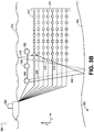
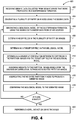
- Figure 4 illustrates a flowchart of a method 400 for generating an image of a subterranean formation, according to an embodiment. More particularly, the method 400 may enhance a raw image of the subterranean formation.
- the method 400 may generate the image using interpreted guided image enhancement ("IGIE").
- IGIE interpreted guided image enhancement
- the method 400 may begin by receiving seismic data collected from seismic waves that were propagated in a subterranean formation, as at 402.
- the method 400 may then include generating a plurality of partition images using the seismic data, as at 404.
- a "partition image” refers to an image generated by summation over selected sources (e.g., a subset of the sources) rather than every source, and the selection is based on the relative positions of the sources to the image point.
- data is obtained from many sources (i.e., shots, a source is a seismic wave emitted by vibroseis or airgun).
- the data for the respective sources may be processed to generate an image.
- the images of the sources may be summed to obtain a full image. If the summation is not over every source, but merely a subset of the sources, selected according to the relative positions of the sources to the image point, then a partition image is generated. The selection is according to the relative position of sources, not the absolute position of the sources, which means different points in a partition image may select different sources to sum.
- the rule of selection for the partition image 1 (2) is that sources are on the left (right) side of the image point.
- its partition 2 is the sum of the other 5 sources
- the selected sources for point A and B in partition 1 are different.
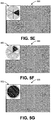
- FIGS 5A-5F illustrate a plurality of partition images of the subterranean formation (six are shown: 510, 520, 530, 540, 550, 560), according to an embodiment.
- the partition images 510, 520, 530, 540, 550, 560 may represent reverse time migrations ("RTMs") of the subterranean formation.
- RTMs reverse time migrations
- the relative azimuth directions of the sources with respect to the image point in partition images 510, 520, 530, 540, 550, 560 are represented by the shaded area in the boxes 512, 522, 532, 542, 552, 562. It may be seen that the partition images 510, 520, 530, 540, 550, 560 illuminate different dipping directions. In practice, a greater or fewer number of partition images 510, 520, 530, 540, 550, 560 may be used.
- the respective partition images 510, 520, 530, 540, 550, 560 may include one or more vector image partitions ("VIPs").
- VIPs vector image partitions
- a "vector image partition” or “VIP” refers to the direct output of RTMs formed during the process of collection and summation over seismic sources, in which each output location collects a portion of the sources based on a particular criterion of its relative position to the sources.
- the respective partition images 510, 520, 530, 540, 550, 560 may include eight VIPs, represented by the eight concentric rings inside the boxes 512, 522, 532, 542, 552, 562.
- the first partition image 510 may be produced by aggregating (e.g., stacking) its corresponding eight VIPS
- the second partition image 520 may be produced by aggregating (e.g., stacking) its corresponding eight VIPS
- the VIPs are also a type of partition image, and different VIPs may illuminate different dipping directions.
- Figure 5G illustrates a raw image 570 of the subterranean formation that is generated using the seismic data, according to an embodiment.
- the partition images 510, 520, 530, 540, 550, 560 may be aggregated (e.g., stacked) to produce the raw image 570.
- the raw image 570 may represent a reverse time migration ("RTM") of the subterranean formation.
- RTM reverse time migration
- the method 400 may also include generating a geological model of the subterranean formation using the seismic data and/or data from other sources (e.g., a downhole tool in a wellbore), as at 406.
- the geological model may include a target area 852 (see Figure 6 ).
- a target area refers to a portion of the subterranean formation identified by a user where the user intends to increase the accuracy.
- the geological model may be or include the raw image 570 having one or more interpreted horizons overlaid thereon.
- Figure 6 illustrates the raw image 570 of the subterranean formation (e.g., from Figure 5G ) with one or more interpreted horizons (five are shown: 571-575) overlaid thereon, according to an embodiment.
- an "interpreted horizon" refers to a model or prediction of a surface in a rock, a surface of rock, a distinctive layer of rock, or an interface between two rocks that is represented by a reflection in seismic data.
- the interface may be or include the contact between two bodies of rock having different seismic velocity, density, porosity, fluid content, or a combination thereof.
- the interpreted horizons 571-575 may be generated using the seismic data and/or data obtained from a downhole tool in a wellbore.
- the downhole tool may be or include a measurement-while-drilling ("MWD”) tool, a logging-while-drilling (“LWD”) tool, or the like.
- the data obtained by the downhole tool may be or include pressure, temperature, wellbore trajectory, resistivity, porosity, sonic velocity, gamma ray, or a combination thereof.
- the geological model may be or include a reference image (e.g., the raw image 570) with a clear skeleton of the geologic structure of the subterranean formation, such as a post-processed enhanced image.
- a reference image e.g., the raw image 570
- a clear skeleton of the geologic structure of the subterranean formation such as a post-processed enhanced image.
- the method 400 may also include determining dip fields in the plurality of partition images 510, 520, 530, 540, 550, 560, as at 408.
- Figures 7A and 7B illustrate the partition images 510, 550 from Figures 5A and 5E , respectively, with circles around their (determined) dip fields 514, 554, according to an embodiment.
- a "dip field” refers to a local trend of the slope of the geologic structure at respective points in the subterranean formation. The dip fields may be determined by differentiating the depth of the geologic structure along the two horizontal directions.
- determining the dip fields for the plurality of partition images 510, 520, 530, 540, 550, 560 may include determining dip fields for the VIPs that make up the partition images 510, 520, 530, 540, 550, 560.
- the respective partition images 510, 520, 530, 540, 550, 560 may illuminate different dipping directions.
- the respective partition images 510, 520, 530, 540, 550, 560 may have their own (e.g., unique) three-dimensional ("3D") dip fields.
- the term "illuminate” refers to seismic wave energy falling on or bouncing off of a reflector and the reflecting being detected.
- the term "dipping direction” refers to a direction that is normal (i.e., perpendicular) to the surface of the reflector.
- the method 400 may also include determining a target dip field 580 in the geological model (e.g., in the raw image 570 with the interpreted horizons 571-575), as at 410.
- a target dip field refers to a dip field in the geological model that the user wants to illuminate. As shown, a circle is placed around the target dip field 580. A majority of the illumination of the target dip field 580 may come from a subset of the partition images 510, 520, 530, 540, 550, 560. This may be the case, for example, for a high dipping event or a complicated velocity model in the subsalt area.
- the method 400 may also include determining a degree of correlation between the dip fields (e.g., dip fields 514, 554) in the partition images 510, 520, 530, 540, 550, 560 and the target dip field 580 in the geological model (e.g., in the raw image 570 with the interpreted horizons 571-575), as at 412.
- the dip fields 514, 554 in the partition images 510, 550 may have a higher degree of correlation (i.e., be "closer") to the target dip field 580 in the geological model (e.g., in the raw image 570 with the interpreted horizons 571-575) than the dip fields in the other partition images 520, 530, 540, 560.
- the seismic event(s) in the dip fields 514, 554 in the partition images 510, 550 may have a higher degree of correlation with the horizons 571-575 in the target dip field 580 in the geological model than the seismic event(s) in the dip fields in the other partition images 520, 530, 540, 560.
- Dip fields with higher degrees of correlation may better illuminate the target dip field 580, whereas dip fields with lower degrees of correlation may introduce noise to the target dip field 580.
- “noise” refers to disturbances in the seismic data that make the seismic event in the target dip field 580 more difficult to observe. The noise may be caused by unwanted seismic energy, such as shot generation ground roll, surface waves, multiples, or a combination thereof.
- the degree of correlation in the partition images 510, 550 may be greater than or equal to a predetermined amount, and the degree of correlation in the partition images 520, 530, 540, 560 may be less than the predetermined amount.
- the degree of correlation may be determined by the relative angle between the dip field in the partition images 510, 520, 530, 540, 550, 560 and the target dip field 580. Smaller angles result in greater degrees of correlation. Similarly, larger angles results in lesser degrees of correlation.
- the method 400 may also include assigning weights to the partition images 510, 520, 530, 540, 550, 560 based upon the degrees of correlation to produce weighted partition images, as at 414. In at least one embodiment, this may include assigning weights to the VIPs that make up the partition images 510, 520, 530, 540, 550, 560 (e.g., based upon the degrees of correlation in the VIPs). The weights may depend (e.g., directly) upon the degrees of correlation. In other words, higher weights may be assigned to partition images 510, 550 with higher degrees of correlation, and lower weights may be assigned to partition images 520, 530, 540, 560 with lower degrees of correlation.
- the method 400 may also include aggregating (e.g., stacking) the weighted partition images 510, 520, 530, 540, 550, 560 to produce an image, as at 416.
- Figure 8 illustrates an image 800 of the subterranean formation produced by aggregating the weighted partition images 510, 520, 530, 540, 550, 560, according to an embodiment.
- the raw image 570 in Figure 5G and the image 800 in Figure 8 may be produced by aggregating (e.g., stacking) the partition images 510, 520, 530, 540, 550, 560.
- the raw image 570 in Figure 5G is produced by aggregating (e.g., stacking) unweighted partition images 510, 520, 530, 540, 550, 560
- the image 800 in Figure 8 may be produced by aggregating (e.g., stacking) weighted partition images 510, 520, 530, 540, 550, 560.
- unweighted refers to partition images and/or VIPs that are factored into the aggregation (e.g., stacking) evenly.
- a percentage that the respective partition images 510, 520, 530, 540, 550, 560 contribute to the image 570 may be the same.
- the respective unweighted partition images 510, 520, 530, 540, 550, 560 may account for 1/6 of the raw image 570.
- the respective unweighted VIPs in the partition images 510, 520, 530, 540, 550, 560 may account for 1/48 of the raw image 570.
- the term "weighted” refers to partition images or VIPS that may be factored into the aggregation (e.g., stacking) unevenly, depending upon the degrees of correlation.
- a percentage that the respective partition images 510, 520, 530, 540, 550, 560 contribute to the image 570 may not be the same (e.g., when the degrees of correlation are not the same).
- the partition images 510, 550 may have their percentages increased because they have degrees of correlation greater than a predetermined amount
- the partition images 520, 530, 540, 560 may have their percentages decreased because they have degrees of correlation less than the predetermined amount.
- the partition image 510 may account for 1/3 of the image 800
- the partition image 550 may account for 1/3 of the image 800
- the respective partition images 520, 530, 540, 560 may account for 1/12 of the image 800.
- This may have the effect of amplifying or boosting the seismic signals in the directions that illuminate the target dip field 580 (i.e., the directions that produced partition images 510, 550), and reducing or suppressing the seismic signals in the directions that introduced noise to the target dip field 580 (i.e., the directions that produced partition images 520, 530, 540, 560).
- the partition image 510 may have contribute a greater percentage to the image 800 than the partition image 550.
- the VIPs that make up the respective partition images 510, 520, 530, 540, 550, 560 may have the same weights/percentages, or the VIPs may have different weights/percentages (e.g., when the VIPs in the respective 510, 520, 530, 540, 550, 560 have different degrees of correlation).
- the method 400 may also include comparing the geological model (e.g., in the raw image 570 with the interpreted horizons 571-575) to the image 800, as at 418. Another iteration of at least a portion of the method 400 may be performed using the image 800 as the raw image when similarities between the geological model and the image 800 are less than a predetermined amount (i.e., not a match).
- the method 400 may also include performing a drilling action using the image 800, as at 420.
- the drilling action may be performed when the similarities between the geological model and the image 800 are greater than or equal to than the predetermined amount (i.e., a match).
- the drilling action may include drilling a wellbore at a predetermined location in response to the data in the image 800 (e.g., the target dip field 580).
- the drilling action may include varying a trajectory of a downhole tool to vary a trajectory of the wellbore in response to the data in the image 800 (e.g., the target dip field 580).
- the drilling action may include varying a weight-on-bit ("WOB") of the downhole tool at one or more locations in the subterranean formation in response to the data in the image 800 (e.g., the target dip field 580).
- WB weight-on-bit
- the drilling action may include varying a flow rate of fluid being pumped into the wellbore in response to the data in the image 800 (e.g., the target dip field 580).
- the drilling action may include measuring one or more parameters in the subterranean formation using the downhole tool in response to the data in the image 800 (e.g., the target dip field 580).
- the downhole tool may be or include a measurement-while-drilling ("MWD”) tool, a logging-while-drilling (“LWD”) tool, or the like.
- the parameters measured by the downhole tool may be or include pressure, temperature, wellbore trajectory, resistivity, porosity, sonic velocity, gamma ray, or a combination thereof.
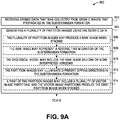
- FIGS 9A and 9B illustrate another flowchart of a method 900 for generating an image of a subterranean formation, according to an embodiment.
- the method 900 may include receiving seismic data that was collected from seismic waves that propagated in the subterranean formation, as at 902.
- the method 900 may also include generating a plurality of partition images using the seismic data, as at 904.
- the plurality of partition images may produce a raw image when stacked, as at 906.
- the raw image may represent a reverse time migration of the subterranean formation, as at 908.
- the geological model may include the raw image and one or more interpreted horizons, as at 910.
- the partition images may illuminate different dipping directions in the subterranean formation, as at 912.
- a first of the partition images may include a plurality of vector image partitions, and the vector image partitions produce the first partition image when stacked, as at 914.
- the method 900 may also include generating a geological model of the subterranean formation using the seismic data, data from a downhole tool in a wellbore, or a combination thereof, as at 916.
- the method 900 may also include determining dip fields in the plurality of partition images, as at 918.
- the method 900 may also include determining a target dip field in the geological model, as at 920.
- the method 900 may also include determining a degree of correlation between the respective dip fields and the target dip field, as at 922.
- the method 900 may also include assigning weights to the partition images based upon the degrees of correlation to produce weighted partition images, as at 924.
- Assigning weights to the partition images may include increasing a percentage that a first of the partition images contributes to the image when the weighted partition images are stacked, where the degree of correlation of the first partition image is greater than or equal to a predetermined amount, as at 926. Assigning weights to the partition images may also include decreasing a percentage that a second of the partition images contributes to the image when the weighted partition images are stacked, where the degree of correlation of the second partition image is less than the predetermined amount, as at 928.
- the method 900 may also include generating the image of the subterranean formation by stacking the weighted partition images, as at 930.
- the method 900 may also include comparing the image of the subterranean formation to the geological model, and performing another iteration of at least a portion of the method 900 using the image as the geological model when similarities between the image of the subterranean formation and the geological model are less than a predetermined amount, as at 932.
- the method 900 may also include performing a drilling action using the image of the subterranean formation, as at 934.
- FIG. 10 illustrates a schematic view of a computing or processor system for performing the method, according to an embodiment.
- the computing system 1000 may include a computer or computer system 1001A, which may be an individual computer system 1001A or an arrangement of distributed computer systems.
- the computer system 1001A includes one or more analysis modules 1002 that are configured to perform various tasks according to some embodiments, such as one or more methods disclosed herein. To perform these various tasks, the analysis module 1002 executes independently, or in coordination with, one or more processors 1004, which is (or are) connected to one or more storage media 1006.
- the processor(s) 1004 is (or are) also connected to a network interface 1007 to allow the computer system 1001A to communicate over a data network 1009 with one or more additional computer systems and/or computing systems, such as 1001B, 1001C, and/or 1001D (note that computer systems 1001B, 1001C and/or 1001D may or may not share the same architecture as computer system 1001A, and may be located in different physical locations, e.g., computer systems 1001A and 1001B may be located in a processing facility, while in communication with one or more computer systems such as 1001C and/or 1001D that are located in one or more data centers, and/or located in varying countries on different continents).
- a processor can include a microprocessor, microcontroller, processor module or subsystem, programmable integrated circuit, programmable gate array, or another control or computing device.
- the storage media 1006 can be implemented as one or more computer-readable or machine-readable storage media. Note that while in some example embodiments of Figure 10 storage media 1006 is depicted as within computer system 1001A, in some embodiments, storage media 1006 may be distributed within and/or across multiple internal and/or external enclosures of computing system 1001A and/or additional computing systems.
- Storage media 1006 may include one or more different forms of memory including semiconductor memory devices such as dynamic or static random access memories (DRAMs or SRAMs), erasable and programmable read-only memories (EPROMs), electrically erasable and programmable read-only memories (EEPROMs) and flash memories, magnetic disks such as fixed, floppy and removable disks, other magnetic media including tape, optical media such as compact disks (CDs) or digital video disks (DVDs), BLUERAY® disks, or other types of optical storage, or other types of storage devices.
- semiconductor memory devices such as dynamic or static random access memories (DRAMs or SRAMs), erasable and programmable read-only memories (EPROMs), electrically erasable and programmable read-only memories (EEPROMs) and flash memories
- magnetic disks such as fixed, floppy and removable disks, other magnetic media including tape
- optical media such as compact disks (CDs) or digital video disks (DVDs), BLUERAY® disks, or other
- Such computer-readable or machine-readable storage medium or media is (are) considered to be part of an article (or article of manufacture).
- An article or article of manufacture can refer to any manufactured single component or multiple components.
- the storage medium or media can be located either in the machine running the machine-readable instructions, or located at a remote site from which machine-readable instructions can be downloaded over a network for execution.
- computing system 1000 contains one or more IGIE module(s) 1008.
- computer system 1001A includes the IGIE module 1008.
- a single IGIE module may be used to perform at least some aspects of one or more embodiments of the method 400 disclosed herein.
- a plurality of IGIE modules may be used to perform at least some aspects of method 400 disclosed herein.
- computing system 1000 is but one example of a computing system, and that computing system 1000 may have more or fewer components than shown, may combine additional components not depicted in the example embodiment of Figure 10 , and/or computing system 1000 may have a different configuration or arrangement of the components depicted in Figure 10 .
- the various components shown in Figure 10 may be implemented in hardware, software, or a combination of both hardware and software, including one or more signal processing and/or application specific integrated circuits.
- steps in the processing methods described herein may be implemented by running one or more functional modules in information processing apparatus such as general purpose processors or application specific chips, such as ASICs, FPGAs, PLDs, or other appropriate devices.
- ASICs general purpose processors or application specific chips, such as ASICs, FPGAs, PLDs, or other appropriate devices.
- Geologic interpretations, models and/or other interpretation aids may be refined in an iterative fashion; this concept is applicable to methods as discussed herein.
- This can include use of feedback loops executed on an algorithmic basis, such as at a computing device (e.g., computing system 1000, Figure 10 ), and/or through manual control by a user who may make determinations regarding whether a given step, action, template, model, or set of curves has become sufficiently accurate for the evaluation of the subsurface three-dimensional geologic formation under consideration.
Landscapes
- Engineering & Computer Science (AREA)
- Physics & Mathematics (AREA)
- Geology (AREA)
- Life Sciences & Earth Sciences (AREA)
- Mining & Mineral Resources (AREA)
- General Physics & Mathematics (AREA)
- Theoretical Computer Science (AREA)
- Fluid Mechanics (AREA)
- Environmental & Geological Engineering (AREA)
- General Life Sciences & Earth Sciences (AREA)
- Geochemistry & Mineralogy (AREA)
- Geophysics And Detection Of Objects (AREA)
- General Engineering & Computer Science (AREA)
- Operations Research (AREA)
Claims (12)
- Procédé (400) destiné à générer une image d'une formation souterraine (306), comprenant :
la réception (402) des données sismiques qui étaient recueillies à partir d'ondes sismiques propagées dans la formation souterraine ;
la génération (404) d'une pluralité d'images de partition (510-560) à l'aide des données sismiques ; la génération (406) d'un modèle géologique de la formation souterraine ;
la détermination (408) des champs d'inclinaison (514,554) dans la pluralité d'images de partition (510-560) ; la détermination (410) d'un champ d'inclinaison cible (580) dans le modèle géologique ;
la détermination (412) d'un degré de corrélation entre les champs d'inclinaison respectifs (514, 554) et le champ d'inclinaison cible (580) ;
l'attribution de poids (414) aux images de partition (510-560) en fonction des degrés de corrélation pour produire des images de partition pondérées ; et
la génération (416) de l'image (800) de la formation souterraine en empilant les images de partition pondérées. - Procédé selon la revendication 1, dans lequel la pluralité d'images de partition produit une image brute (570) lorsqu'elles sont empilées.
- Procédé selon la revendication 2, dans lequel l'image brute (570) représente une migration temporelle inverse de la formation souterraine (306).
- Procédé selon la revendication 3, dans lequel le modèle géologique comprend l'image brute (570) et un ou plusieurs horizons interprétés (571-575).
- Procédé selon une quelconque revendication précédente, dans lequel les images de partition (510-560) éclairent différentes directions d'inclinaison dans la formation souterraine (306).
- Procédé selon une quelconque revendication précédente, dans lequel une première image de partition des images de partition (510-560) comprend une pluralité de partitions d'image vectorielle et dans laquelle les partitions d'image vectorielle produisent la première image de partition (570) lorsqu'elles sont empilées.
- Procédé selon une quelconque revendication précédente, dans lequel l'attribution de poids (414) aux images de partition (510-560) comprend l'augmentation d'un pourcentage qu'une première image de partition des images de partition contribue à l'image lorsque les images de partition pondérées sont empilées, dans lequel le degré de corrélation de la première image de partition est supérieur ou égal à une quantité prédéfinie.
- Procédé selon la revendication 7, dans lequel l'attribution de poids (414) aux images de partition (510-560) comprend la diminution d'un pourcentage qu'une seconde image de partition des images de partition (510-560) contribue à l'image lorsque les images de partition pondérées sont empilées, dans lequel le degré de corrélation de la seconde image de partition est inférieur à la quantité prédéfinie.
- Procédé selon une quelconque revendication précédente, comprenant en outre :la comparaison de (418) l'image de la formation souterraine (306) au modèle géologique ; etla réalisation d'une autre itération d'au moins une partie du procédé à l'aide de l'image comme modèle géologique lorsque les similitudes entre l'image de la formation souterraine (306) et le modèle géologique sont inférieures à une quantité prédéfinie.
- Procédé selon une quelconque revendication précédente, comprenant en outre la réalisation (420) d'une action de forage à l'aide de l'image de la formation souterraine.
- Instruction de stockage de support non transitoire lisible par ordinateur qui, lorsqu'elle est exécutée par un ou plusieurs processeurs (1004) d'un système informatique (1000), amène le système informatique à réaliser le procédé selon une quelconque revendication précédente.
- Système informatique (1000), comprenant :un ou plusieurs processeurs (1004) ; etun système de mémoire (1006) comprenant une ou plusieurs instructions de stockage de supports non transitoires lisibles par ordinateur qui, lorsqu'elles sont exécutées par au moins parmi le ou les processeurs (1004), amènent le système informatique à réaliser le procédé selon l'une quelconque des revendications 1 à 10.
Applications Claiming Priority (2)
| Application Number | Priority Date | Filing Date | Title |
|---|---|---|---|
| US15/059,078 US10535168B2 (en) | 2016-03-02 | 2016-03-02 | Image enhancement using seismic partition images |
| PCT/US2017/019800 WO2017151529A1 (fr) | 2016-03-02 | 2017-02-28 | Amélioration d'image au moyen d'images de partition sismique |
Publications (3)
| Publication Number | Publication Date |
|---|---|
| EP3423870A1 EP3423870A1 (fr) | 2019-01-09 |
| EP3423870A4 EP3423870A4 (fr) | 2019-11-13 |
| EP3423870B1 true EP3423870B1 (fr) | 2020-11-18 |
Family
ID=59723752
Family Applications (1)
| Application Number | Title | Priority Date | Filing Date |
|---|---|---|---|
| EP17760561.5A Active EP3423870B1 (fr) | 2016-03-02 | 2017-02-28 | Amélioration d'image au moyen d'images de partition sismique |
Country Status (3)
| Country | Link |
|---|---|
| US (1) | US10535168B2 (fr) |
| EP (1) | EP3423870B1 (fr) |
| WO (1) | WO2017151529A1 (fr) |
Families Citing this family (3)
| Publication number | Priority date | Publication date | Assignee | Title |
|---|---|---|---|---|
| US11899151B2 (en) * | 2017-12-18 | 2024-02-13 | Pgs Geophysical As | Surveying techniques using multiple different types of sources |
| US11062511B2 (en) * | 2019-05-02 | 2021-07-13 | Deere & Company | Controlling mobile construction equipment for subterranean mapping |
| US11531131B2 (en) * | 2020-01-16 | 2022-12-20 | Schlumberger Technology Corporation | Seismic interpretation using flow fields |
Family Cites Families (8)
| Publication number | Priority date | Publication date | Assignee | Title |
|---|---|---|---|---|
| US8463551B2 (en) * | 2009-11-17 | 2013-06-11 | Schlumberger Technology Corporation | Consistent dip estimation for seismic imaging |
| US8760967B2 (en) | 2010-10-15 | 2014-06-24 | Westerngeco L.L.C. | Generating an angle domain common image gather |
| WO2012107792A1 (fr) | 2011-02-08 | 2012-08-16 | Total Sa | Procédé d'analyse de données sismiques |
| US10162070B2 (en) | 2012-04-05 | 2018-12-25 | Westerngeco L.L.C. | Converting a first acquired data subset to a second acquired data subset |
| EP2885656B1 (fr) | 2012-08-17 | 2018-09-26 | Landmark Graphics Corporation | Procédés permettant d'imager des données sismiques |
| US9134452B2 (en) * | 2012-12-10 | 2015-09-15 | Schlumberger Technology Corporation | Weighting function for inclination and azimuth computation |
| US9726772B2 (en) | 2013-10-17 | 2017-08-08 | Westerngeco L.L.C. | Iterative stacking of seismic image partitions |
| US20160291183A1 (en) * | 2015-04-01 | 2016-10-06 | Chevron U.S.A. Inc. | System and method for seismic imaging of complex subsurface volumes |
-
2016
- 2016-03-02 US US15/059,078 patent/US10535168B2/en active Active
-
2017
- 2017-02-28 EP EP17760561.5A patent/EP3423870B1/fr active Active
- 2017-02-28 WO PCT/US2017/019800 patent/WO2017151529A1/fr active Application Filing
Non-Patent Citations (1)
| Title |
|---|
| None * |
Also Published As
| Publication number | Publication date |
|---|---|
| US10535168B2 (en) | 2020-01-14 |
| EP3423870A1 (fr) | 2019-01-09 |
| US20170256080A1 (en) | 2017-09-07 |
| EP3423870A4 (fr) | 2019-11-13 |
| WO2017151529A1 (fr) | 2017-09-08 |
Similar Documents
| Publication | Publication Date | Title |
|---|---|---|
| EP3058169B1 (fr) | Sommation itérative de partitions d'images sismiques | |
| US9983323B2 (en) | Performing tomography to build orthorhombic models | |
| US20170176228A1 (en) | Drilling fluid loss rate prediction | |
| EP4147075A1 (fr) | Interprétation de défauts sismiques avec des techniques d'apprentissage machine | |
| WO2016161096A1 (fr) | Traitement de données sismiques | |
| WO2020009850A1 (fr) | Flux de travail d'apprentissage automatique en cascade permettant une interprétation sismique du sel | |
| US20220066061A1 (en) | Combining noise attenuation and wavefield reconstruction in seismic processing | |
| EP3423870B1 (fr) | Amélioration d'image au moyen d'images de partition sismique | |
| US11531131B2 (en) | Seismic interpretation using flow fields | |
| US20220121987A1 (en) | Differential multi model training for multiple interpretation options | |
| US10514475B2 (en) | Post-critical reflection muting in seismic migration | |
| WO2023086396A1 (fr) | Prédiction de corps de volute de co2 dans des opérations de séquestration | |
| US11774620B2 (en) | Interpolation of seismic data with time variant locations | |
| WO2023043925A1 (fr) | Systèmes et procédés de modélisation d'un volume de subsurface à l'aide de données par intervalles de temps | |
| WO2021142406A1 (fr) | Estimation de propriétés de subsurface dans une zone d'étude sismique avec des diagraphies de puits rares | |
| WO2021174178A1 (fr) | Inversion de forme d'onde complète correspondant à un gabarit | |
| WO2022147410A1 (fr) | Apprentissage d'apprentissage machine basé sur des fonctions de double perte | |
| WO2023200696A1 (fr) | Quantification de la diversité dans des ensembles de données sismiques |
Legal Events
| Date | Code | Title | Description |
|---|---|---|---|
| STAA | Information on the status of an ep patent application or granted ep patent |
Free format text: STATUS: THE INTERNATIONAL PUBLICATION HAS BEEN MADE |
|
| PUAI | Public reference made under article 153(3) epc to a published international application that has entered the european phase |
Free format text: ORIGINAL CODE: 0009012 |
|
| STAA | Information on the status of an ep patent application or granted ep patent |
Free format text: STATUS: REQUEST FOR EXAMINATION WAS MADE |
|
| 17P | Request for examination filed |
Effective date: 20180928 |
|
| AK | Designated contracting states |
Kind code of ref document: A1 Designated state(s): AL AT BE BG CH CY CZ DE DK EE ES FI FR GB GR HR HU IE IS IT LI LT LU LV MC MK MT NL NO PL PT RO RS SE SI SK SM TR |
|
| AX | Request for extension of the european patent |
Extension state: BA ME |
|
| RIN1 | Information on inventor provided before grant (corrected) |
Inventor name: HEGAZY, MOHAMMED Inventor name: GU, RUOYU Inventor name: BUZZELL, STACEY Inventor name: ZDRAVEVA, OLGA |
|
| DAV | Request for validation of the european patent (deleted) | ||
| DAX | Request for extension of the european patent (deleted) | ||
| A4 | Supplementary search report drawn up and despatched |
Effective date: 20191010 |
|
| RIC1 | Information provided on ipc code assigned before grant |
Ipc: G01V 1/34 20060101ALI20191004BHEP Ipc: G06T 5/00 20060101AFI20191004BHEP Ipc: G06T 5/50 20060101ALI20191004BHEP |
|
| REG | Reference to a national code |
Ref country code: DE Ref legal event code: R079 Ref document number: 602017027843 Country of ref document: DE Free format text: PREVIOUS MAIN CLASS: G01V0001340000 Ipc: G06T0011000000 |
|
| RIC1 | Information provided on ipc code assigned before grant |
Ipc: G06T 5/00 20060101ALI20200519BHEP Ipc: G06T 11/00 20060101AFI20200519BHEP Ipc: G01V 1/34 20060101ALI20200519BHEP Ipc: G06T 5/50 20060101ALI20200519BHEP |
|
| GRAP | Despatch of communication of intention to grant a patent |
Free format text: ORIGINAL CODE: EPIDOSNIGR1 |
|
| STAA | Information on the status of an ep patent application or granted ep patent |
Free format text: STATUS: GRANT OF PATENT IS INTENDED |
|
| INTG | Intention to grant announced |
Effective date: 20200708 |
|
| RIN1 | Information on inventor provided before grant (corrected) |
Inventor name: ZDRAVEVA, OLGA Inventor name: BUZZELL, STACEY Inventor name: HEGAZY, MOHAMMED Inventor name: GU, RUOYU |
|
| GRAS | Grant fee paid |
Free format text: ORIGINAL CODE: EPIDOSNIGR3 |
|
| GRAA | (expected) grant |
Free format text: ORIGINAL CODE: 0009210 |
|
| STAA | Information on the status of an ep patent application or granted ep patent |
Free format text: STATUS: THE PATENT HAS BEEN GRANTED |
|
| AK | Designated contracting states |
Kind code of ref document: B1 Designated state(s): AL AT BE BG CH CY CZ DE DK EE ES FI FR GB GR HR HU IE IS IT LI LT LU LV MC MK MT NL NO PL PT RO RS SE SI SK SM TR |
|
| REG | Reference to a national code |
Ref country code: GB Ref legal event code: FG4D |
|
| REG | Reference to a national code |
Ref country code: CH Ref legal event code: EP |
|
| REG | Reference to a national code |
Ref country code: IE Ref legal event code: FG4D |
|
| REG | Reference to a national code |
Ref country code: DE Ref legal event code: R096 Ref document number: 602017027843 Country of ref document: DE |
|
| REG | Reference to a national code |
Ref country code: AT Ref legal event code: REF Ref document number: 1336602 Country of ref document: AT Kind code of ref document: T Effective date: 20201215 |
|
| REG | Reference to a national code |
Ref country code: AT Ref legal event code: MK05 Ref document number: 1336602 Country of ref document: AT Kind code of ref document: T Effective date: 20201118 |
|
| REG | Reference to a national code |
Ref country code: NL Ref legal event code: MP Effective date: 20201118 |
|
| PG25 | Lapsed in a contracting state [announced via postgrant information from national office to epo] |
Ref country code: NO Free format text: LAPSE BECAUSE OF FAILURE TO SUBMIT A TRANSLATION OF THE DESCRIPTION OR TO PAY THE FEE WITHIN THE PRESCRIBED TIME-LIMIT Effective date: 20210218 Ref country code: PT Free format text: LAPSE BECAUSE OF FAILURE TO SUBMIT A TRANSLATION OF THE DESCRIPTION OR TO PAY THE FEE WITHIN THE PRESCRIBED TIME-LIMIT Effective date: 20210318 Ref country code: RS Free format text: LAPSE BECAUSE OF FAILURE TO SUBMIT A TRANSLATION OF THE DESCRIPTION OR TO PAY THE FEE WITHIN THE PRESCRIBED TIME-LIMIT Effective date: 20201118 Ref country code: GR Free format text: LAPSE BECAUSE OF FAILURE TO SUBMIT A TRANSLATION OF THE DESCRIPTION OR TO PAY THE FEE WITHIN THE PRESCRIBED TIME-LIMIT Effective date: 20210219 Ref country code: FI Free format text: LAPSE BECAUSE OF FAILURE TO SUBMIT A TRANSLATION OF THE DESCRIPTION OR TO PAY THE FEE WITHIN THE PRESCRIBED TIME-LIMIT Effective date: 20201118 |
|
| PG25 | Lapsed in a contracting state [announced via postgrant information from national office to epo] |
Ref country code: AT Free format text: LAPSE BECAUSE OF FAILURE TO SUBMIT A TRANSLATION OF THE DESCRIPTION OR TO PAY THE FEE WITHIN THE PRESCRIBED TIME-LIMIT Effective date: 20201118 Ref country code: LV Free format text: LAPSE BECAUSE OF FAILURE TO SUBMIT A TRANSLATION OF THE DESCRIPTION OR TO PAY THE FEE WITHIN THE PRESCRIBED TIME-LIMIT Effective date: 20201118 Ref country code: IS Free format text: LAPSE BECAUSE OF FAILURE TO SUBMIT A TRANSLATION OF THE DESCRIPTION OR TO PAY THE FEE WITHIN THE PRESCRIBED TIME-LIMIT Effective date: 20210318 Ref country code: PL Free format text: LAPSE BECAUSE OF FAILURE TO SUBMIT A TRANSLATION OF THE DESCRIPTION OR TO PAY THE FEE WITHIN THE PRESCRIBED TIME-LIMIT Effective date: 20201118 Ref country code: SE Free format text: LAPSE BECAUSE OF FAILURE TO SUBMIT A TRANSLATION OF THE DESCRIPTION OR TO PAY THE FEE WITHIN THE PRESCRIBED TIME-LIMIT Effective date: 20201118 Ref country code: BG Free format text: LAPSE BECAUSE OF FAILURE TO SUBMIT A TRANSLATION OF THE DESCRIPTION OR TO PAY THE FEE WITHIN THE PRESCRIBED TIME-LIMIT Effective date: 20210218 |
|
| REG | Reference to a national code |
Ref country code: LT Ref legal event code: MG9D |
|
| PG25 | Lapsed in a contracting state [announced via postgrant information from national office to epo] |
Ref country code: HR Free format text: LAPSE BECAUSE OF FAILURE TO SUBMIT A TRANSLATION OF THE DESCRIPTION OR TO PAY THE FEE WITHIN THE PRESCRIBED TIME-LIMIT Effective date: 20201118 |
|
| PG25 | Lapsed in a contracting state [announced via postgrant information from national office to epo] |
Ref country code: RO Free format text: LAPSE BECAUSE OF FAILURE TO SUBMIT A TRANSLATION OF THE DESCRIPTION OR TO PAY THE FEE WITHIN THE PRESCRIBED TIME-LIMIT Effective date: 20201118 Ref country code: SK Free format text: LAPSE BECAUSE OF FAILURE TO SUBMIT A TRANSLATION OF THE DESCRIPTION OR TO PAY THE FEE WITHIN THE PRESCRIBED TIME-LIMIT Effective date: 20201118 Ref country code: LT Free format text: LAPSE BECAUSE OF FAILURE TO SUBMIT A TRANSLATION OF THE DESCRIPTION OR TO PAY THE FEE WITHIN THE PRESCRIBED TIME-LIMIT Effective date: 20201118 Ref country code: EE Free format text: LAPSE BECAUSE OF FAILURE TO SUBMIT A TRANSLATION OF THE DESCRIPTION OR TO PAY THE FEE WITHIN THE PRESCRIBED TIME-LIMIT Effective date: 20201118 Ref country code: CZ Free format text: LAPSE BECAUSE OF FAILURE TO SUBMIT A TRANSLATION OF THE DESCRIPTION OR TO PAY THE FEE WITHIN THE PRESCRIBED TIME-LIMIT Effective date: 20201118 Ref country code: SM Free format text: LAPSE BECAUSE OF FAILURE TO SUBMIT A TRANSLATION OF THE DESCRIPTION OR TO PAY THE FEE WITHIN THE PRESCRIBED TIME-LIMIT Effective date: 20201118 |
|
| REG | Reference to a national code |
Ref country code: DE Ref legal event code: R097 Ref document number: 602017027843 Country of ref document: DE |
|
| PG25 | Lapsed in a contracting state [announced via postgrant information from national office to epo] |
Ref country code: DK Free format text: LAPSE BECAUSE OF FAILURE TO SUBMIT A TRANSLATION OF THE DESCRIPTION OR TO PAY THE FEE WITHIN THE PRESCRIBED TIME-LIMIT Effective date: 20201118 |
|
| REG | Reference to a national code |
Ref country code: DE Ref legal event code: R119 Ref document number: 602017027843 Country of ref document: DE |
|
| PLBE | No opposition filed within time limit |
Free format text: ORIGINAL CODE: 0009261 |
|
| STAA | Information on the status of an ep patent application or granted ep patent |
Free format text: STATUS: NO OPPOSITION FILED WITHIN TIME LIMIT |
|
| PG25 | Lapsed in a contracting state [announced via postgrant information from national office to epo] |
Ref country code: MC Free format text: LAPSE BECAUSE OF FAILURE TO SUBMIT A TRANSLATION OF THE DESCRIPTION OR TO PAY THE FEE WITHIN THE PRESCRIBED TIME-LIMIT Effective date: 20201118 |
|
| 26N | No opposition filed |
Effective date: 20210819 |
|
| REG | Reference to a national code |
Ref country code: BE Ref legal event code: MM Effective date: 20210228 |
|
| PG25 | Lapsed in a contracting state [announced via postgrant information from national office to epo] |
Ref country code: NL Free format text: LAPSE BECAUSE OF FAILURE TO SUBMIT A TRANSLATION OF THE DESCRIPTION OR TO PAY THE FEE WITHIN THE PRESCRIBED TIME-LIMIT Effective date: 20201118 Ref country code: AL Free format text: LAPSE BECAUSE OF FAILURE TO SUBMIT A TRANSLATION OF THE DESCRIPTION OR TO PAY THE FEE WITHIN THE PRESCRIBED TIME-LIMIT Effective date: 20201118 Ref country code: CH Free format text: LAPSE BECAUSE OF NON-PAYMENT OF DUE FEES Effective date: 20210228 Ref country code: LU Free format text: LAPSE BECAUSE OF NON-PAYMENT OF DUE FEES Effective date: 20210228 Ref country code: IT Free format text: LAPSE BECAUSE OF FAILURE TO SUBMIT A TRANSLATION OF THE DESCRIPTION OR TO PAY THE FEE WITHIN THE PRESCRIBED TIME-LIMIT Effective date: 20201118 Ref country code: LI Free format text: LAPSE BECAUSE OF NON-PAYMENT OF DUE FEES Effective date: 20210228 |
|
| PG25 | Lapsed in a contracting state [announced via postgrant information from national office to epo] |
Ref country code: SI Free format text: LAPSE BECAUSE OF FAILURE TO SUBMIT A TRANSLATION OF THE DESCRIPTION OR TO PAY THE FEE WITHIN THE PRESCRIBED TIME-LIMIT Effective date: 20201118 |
|
| PG25 | Lapsed in a contracting state [announced via postgrant information from national office to epo] |
Ref country code: IE Free format text: LAPSE BECAUSE OF NON-PAYMENT OF DUE FEES Effective date: 20210228 Ref country code: ES Free format text: LAPSE BECAUSE OF FAILURE TO SUBMIT A TRANSLATION OF THE DESCRIPTION OR TO PAY THE FEE WITHIN THE PRESCRIBED TIME-LIMIT Effective date: 20201118 Ref country code: DE Free format text: LAPSE BECAUSE OF NON-PAYMENT OF DUE FEES Effective date: 20210901 |
|
| PG25 | Lapsed in a contracting state [announced via postgrant information from national office to epo] |
Ref country code: IS Free format text: LAPSE BECAUSE OF FAILURE TO SUBMIT A TRANSLATION OF THE DESCRIPTION OR TO PAY THE FEE WITHIN THE PRESCRIBED TIME-LIMIT Effective date: 20210318 |
|
| PG25 | Lapsed in a contracting state [announced via postgrant information from national office to epo] |
Ref country code: BE Free format text: LAPSE BECAUSE OF NON-PAYMENT OF DUE FEES Effective date: 20210228 |
|
| PGFP | Annual fee paid to national office [announced via postgrant information from national office to epo] |
Ref country code: FR Payment date: 20230110 Year of fee payment: 7 |
|
| PG25 | Lapsed in a contracting state [announced via postgrant information from national office to epo] |
Ref country code: CY Free format text: LAPSE BECAUSE OF FAILURE TO SUBMIT A TRANSLATION OF THE DESCRIPTION OR TO PAY THE FEE WITHIN THE PRESCRIBED TIME-LIMIT Effective date: 20201118 |
|
| PG25 | Lapsed in a contracting state [announced via postgrant information from national office to epo] |
Ref country code: HU Free format text: LAPSE BECAUSE OF FAILURE TO SUBMIT A TRANSLATION OF THE DESCRIPTION OR TO PAY THE FEE WITHIN THE PRESCRIBED TIME-LIMIT; INVALID AB INITIO Effective date: 20170228 |
|
| P01 | Opt-out of the competence of the unified patent court (upc) registered |
Effective date: 20231208 |
|
| PG25 | Lapsed in a contracting state [announced via postgrant information from national office to epo] |
Ref country code: MK Free format text: LAPSE BECAUSE OF FAILURE TO SUBMIT A TRANSLATION OF THE DESCRIPTION OR TO PAY THE FEE WITHIN THE PRESCRIBED TIME-LIMIT Effective date: 20201118 |
|
| PGFP | Annual fee paid to national office [announced via postgrant information from national office to epo] |
Ref country code: GB Payment date: 20240108 Year of fee payment: 8 |