EP3423706B1 - Wind turbine with improved rotor blade screw connection - Google Patents
Wind turbine with improved rotor blade screw connection Download PDFInfo
- Publication number
- EP3423706B1 EP3423706B1 EP17706468.0A EP17706468A EP3423706B1 EP 3423706 B1 EP3423706 B1 EP 3423706B1 EP 17706468 A EP17706468 A EP 17706468A EP 3423706 B1 EP3423706 B1 EP 3423706B1
- Authority
- EP
- European Patent Office
- Prior art keywords
- ring
- segment
- stiffening
- power plant
- wind power
- Prior art date
- Legal status (The legal status is an assumption and is not a legal conclusion. Google has not performed a legal analysis and makes no representation as to the accuracy of the status listed.)
- Active
Links
- 230000001747 exhibiting effect Effects 0.000 claims 1
- 238000009420 retrofitting Methods 0.000 description 5
- 239000003351 stiffener Substances 0.000 description 5
- 230000006378 damage Effects 0.000 description 3
- 239000000463 material Substances 0.000 description 3
- 230000003014 reinforcing effect Effects 0.000 description 3
- 230000015572 biosynthetic process Effects 0.000 description 2
- 239000002131 composite material Substances 0.000 description 2
- 238000010276 construction Methods 0.000 description 2
- 238000005096 rolling process Methods 0.000 description 2
- 229920000049 Carbon (fiber) Polymers 0.000 description 1
- 208000027418 Wounds and injury Diseases 0.000 description 1
- 238000004026 adhesive bonding Methods 0.000 description 1
- 238000005452 bending Methods 0.000 description 1
- 239000004917 carbon fiber Substances 0.000 description 1
- 230000001419 dependent effect Effects 0.000 description 1
- 230000000694 effects Effects 0.000 description 1
- 239000000835 fiber Substances 0.000 description 1
- 208000014674 injury Diseases 0.000 description 1
- 238000004519 manufacturing process Methods 0.000 description 1
- VNWKTOKETHGBQD-UHFFFAOYSA-N methane Chemical compound C VNWKTOKETHGBQD-UHFFFAOYSA-N 0.000 description 1
- 238000000034 method Methods 0.000 description 1
- 230000002093 peripheral effect Effects 0.000 description 1
- 238000010079 rubber tapping Methods 0.000 description 1
- 238000010008 shearing Methods 0.000 description 1
Images
Classifications
-
- F—MECHANICAL ENGINEERING; LIGHTING; HEATING; WEAPONS; BLASTING
- F03—MACHINES OR ENGINES FOR LIQUIDS; WIND, SPRING, OR WEIGHT MOTORS; PRODUCING MECHANICAL POWER OR A REACTIVE PROPULSIVE THRUST, NOT OTHERWISE PROVIDED FOR
- F03D—WIND MOTORS
- F03D1/00—Wind motors with rotation axis substantially parallel to the air flow entering the rotor
- F03D1/06—Rotors
- F03D1/065—Rotors characterised by their construction elements
- F03D1/0658—Arrangements for fixing wind-engaging parts to a hub
-
- F—MECHANICAL ENGINEERING; LIGHTING; HEATING; WEAPONS; BLASTING
- F05—INDEXING SCHEMES RELATING TO ENGINES OR PUMPS IN VARIOUS SUBCLASSES OF CLASSES F01-F04
- F05B—INDEXING SCHEME RELATING TO WIND, SPRING, WEIGHT, INERTIA OR LIKE MOTORS, TO MACHINES OR ENGINES FOR LIQUIDS COVERED BY SUBCLASSES F03B, F03D AND F03G
- F05B2260/00—Function
- F05B2260/70—Adjusting of angle of incidence or attack of rotating blades
- F05B2260/79—Bearing, support or actuation arrangements therefor
-
- F—MECHANICAL ENGINEERING; LIGHTING; HEATING; WEAPONS; BLASTING
- F05—INDEXING SCHEMES RELATING TO ENGINES OR PUMPS IN VARIOUS SUBCLASSES OF CLASSES F01-F04
- F05B—INDEXING SCHEME RELATING TO WIND, SPRING, WEIGHT, INERTIA OR LIKE MOTORS, TO MACHINES OR ENGINES FOR LIQUIDS COVERED BY SUBCLASSES F03B, F03D AND F03G
- F05B2280/00—Materials; Properties thereof
- F05B2280/70—Treatments or modification of materials
- F05B2280/702—Reinforcements
-
- Y—GENERAL TAGGING OF NEW TECHNOLOGICAL DEVELOPMENTS; GENERAL TAGGING OF CROSS-SECTIONAL TECHNOLOGIES SPANNING OVER SEVERAL SECTIONS OF THE IPC; TECHNICAL SUBJECTS COVERED BY FORMER USPC CROSS-REFERENCE ART COLLECTIONS [XRACs] AND DIGESTS
- Y02—TECHNOLOGIES OR APPLICATIONS FOR MITIGATION OR ADAPTATION AGAINST CLIMATE CHANGE
- Y02E—REDUCTION OF GREENHOUSE GAS [GHG] EMISSIONS, RELATED TO ENERGY GENERATION, TRANSMISSION OR DISTRIBUTION
- Y02E10/00—Energy generation through renewable energy sources
- Y02E10/70—Wind energy
- Y02E10/72—Wind turbines with rotation axis in wind direction
Definitions
- the present invention relates to a wind turbine with a rotor hub and at least one rotor blade, which is fastened by means of a arranged between the rotor hub and the rotor blade bearing on the rotor hub.
- the outer ring is connected by means of a plurality of fastening bolts with the rotor hub, wherein end-side threaded portions of the fastening bolts are screwed into threaded bores of the rotor hub, and wherein fastening nuts are screwed onto protruding from the outer ring threaded portions of the fastening bolts.
- the rotor blade is therefore rotatably mounted with respect to the rotor hub about the longitudinal axis of the rotor blade.
- wind energy plants are known from the state of the art, in which the outer rings of the blade bearings are each connected to the rotor blades and the inner rings of the blade bearings are each connected to the rotor hubs of the wind energy plant.
- the connecting bolts for connecting the rotor blades to the blade bearing are usually designed as expansion bolts.
- an expansion region with a reduced outer diameter is arranged between end-side threaded sections of the expansion bolts.
- the respective fastening nuts For a reliable attachment of the rotor blade to the rotor hub, the respective fastening nuts must be tightened with predetermined torques or mounted with biasing forces, so that a self-locking between the threaded portions and the fastening nuts used, whereby a loosening of the fastening nuts is prevented by the respective threaded portions.
- a cause of the self-loosening of screws and fastening nuts may be too elastic a construction of rotor hub, blade bearing and rotor blade.
- One remedy might be to form a stiffer overall design, which, however, can only be implemented in the field with significant development, manufacturing, certification, and logistics costs and would add significant cost.
- the US 2014/0377069 A1 describes a wind turbine with a rotor color and a plurality of rotor blades, which are connected via a ball bearing device with the rotor color.
- the ball bearing device has an inner ring and an outer ring, wherein each rotor blade are connected by means of fastening screws with the inner ring, and wherein the outer ring is connected via fastening screws with the rotor color.
- a stiffening device which may comprise a plurality of ring segments, each having mounting holes through which the fastening bolts are passed, so that the inner ring between the rotor blade and the stiffening device is arranged.
- the WO 2007/003866 A1 also shows a wind turbine with a rotor color and a plurality of rotor blades which are connected via an inner ring and an outer ring bearing ball bearing device with the rotor color. Further, the wind turbine on an outer plate and an inner plate, wherein the outer plate is connected to the outer ring such that the outer ring between the rotor and the outer plate is arranged, and wherein the inner plate is connected to the inner ring such that the inner ring between the inner plate and the rotor blade is arranged. Both the outer plate and the inner plate have a plurality of through holes through which fastening screws protrude.
- the EP 2045464 A2 also describes a wind turbine with a rotor color, a blade bearing having an outer ring and an inner ring, and a plurality of rotor blades, which are connected via the blade bearings with the rotor color.
- the present invention has for its object to provide a wind turbine with an improved rotor blade.
- the object underlying the present invention is achieved by a wind turbine with a rotor hub, at least one blade bearing and at least one rotor blade, wherein the blade bearing has a first ring and a second ring which are concentric to each other rotatable.
- the first ring is connected to the rotor blade by means of at least one first connecting bolt passing through a first through-bore of the first ring.
- the second ring is connected to the rotor hub by means of at least one second connecting bolt passing through a respective second through-bore of the second ring.
- the wind power plant according to the invention is characterized in that it comprises at least one stiffening device with at least one through opening through which the first connecting bolt and / or the second connecting bolt protrude, wherein the stiffening device by means of at least one fastening nut, which protrudes on a protruding from the stiffening threaded portion of first connecting bolt and / or the second connecting bolt is screwed, is subjected to force in the direction of the sheet bearing.
- the stiffening device through which the first connecting bolt and / or the second connecting bolt protrude, the transverse forces and bending moments, which acts on the connection bolts when the rotor blades are loaded, compared with a larger moment of resistance.
- slippage of the rotor blade with respect to the first ring and / or slippage of the second ring with respect to the rotor hub is counteracted.
- the blade bearing can also be referred to as a bearing unit.
- the first ring and the second ring are thus arranged concentrically with each other and rotatable relative to each other. Since the first ring is rotatable with respect to the second ring, the rotor blade is rotatable about its longitudinal axis with respect to the rotor hub.
- Both the first connecting bolt and the second connecting bolt can each be designed as stud bolts and / or as expansion bolts.
- the first connecting bolt has at each end a threaded portion.
- a second end-side threaded portion of the first connecting bolt may be screwed into a threaded bore of the rotor blade.
- a first end threaded portion of the first connecting bolt may protrude from the first ring and a fastening nut may be threaded onto the first threaded portion. Consequently, at least one of the first through-holes of the first ring passing through first connecting bolt is connected by means of a second end-side threaded portion with the rotor blade and a first fastening nut is screwed onto a first end threaded portion.
- the second connecting bolt has at its end in each case a threaded portion.
- a second end-side threaded portion of the second connecting bolt may be screwed into a threaded bore of the rotor hub.
- a first end threaded portion of the second connecting bolt may protrude from the second ring and a fastening nut may be threaded onto the first threaded portion. Consequently, at least one second connecting bolt passing through in each case second through-holes of the second ring is connected to the rotor hub by means of a second end-side threaded section, and a second fastening nut is screwed onto a first end-side threaded section.
- first ring is connected to the rotor blade by means of a plurality of first connecting pins, which are each passed through first through holes of the first ring, which are arranged angularly offset from each other in the first ring and preferably extend over the entire circumference of the first ring.
- the second ring is connected to the rotor hub by means of a plurality of second connecting bolts, each passed through second through-holes of the second ring, angularly offset from one another in the second ring and preferably extending over the entire circumference of the second ring.
- the number of first through holes thus corresponds to the number of first connecting bolts.
- the second connecting bolt is preferably connected to the rotor hub by means of the first threaded portion of the connecting bolt, characterized in that the second threaded portion is screwed into a threaded bore of the rotor hub.
- the stiffening device has at least one first stiffening segment, and the first ring of the blade bearing is arranged between the first stiffening segment and the rotor blade, wherein the first stiffening segment is subjected to a force in the direction of the first ring by means of a fastening nut.
- the first stiffening segment is formed as a first partial ring segment, which has a radius of curvature which corresponds to a radius of curvature of the first ring.
- stiffening device has the advantage that retrofitting a wind turbine with the stiffening device is simplified, since not all fastening nuts, by means of which the rotor blade are attached to the first ring of the blade bearing, must be solved at the same time. This reduces the cost of upgrading a wind turbine.
- the first stiffening segment has a multiplicity of passage openings, each of which is aligned with first through-holes of the first ring and in each case penetrated by first connecting pins.
- the first stiffening segment is formed as a first ring segment.
- the moment of resistance increases again and it can form a positive connection between the bearing ring and the rotor blade, so that slippage of the rotor blade with respect to the first ring of the blade bearing is further improved counteracted.
- the first ring segment has a number of through holes corresponding to the number of through holes in the first ring, each aligned with first through holes of the first ring and each interspersed by first connecting pin.
- the stiffening device has at least one clip, which is connected to the first stiffening segment and to the rotor blade, so that forces exerted on the rotor blade can be transmitted at least partially to the first stiffening element via the clip.
- An appropriate design of the wind turbine has the advantage that an additional load path between the rotor blade and the first ring is formed, so that forces exerted on the rotor blade forces are transmitted not only only by the first connecting bolt on the bearing ring, but also on the bracket / the brackets be transferred from the rotor blade to the first ring of the blade bearing. As a result, the stability of the wind turbine is increased again. Because the respective first connecting bolts are relieved, so that the load of the fastening nuts, by means of which the rotor blade is secured to the bearing ring is reduced.
- the attachment of the respective retaining clips on the first stiffening segment can be done for example by a screw.
- the first stiffening device preferably has a threaded bore and the respective brackets each have a through opening through which respective connecting bolts are passed, wherein the respective brackets are fastened by means of fastening nuts to the first stiffening segments.
- the connection between the respective brackets and the rotor blade can also be realized by a screw. Furthermore, it is also possible that the connection of the respective clamps with the rotor blade takes place by means of a bond.
- the stiffening device preferably has at least one second stiffening segment, the second ring of the blade bearing being arranged between the second stiffening segment and the rotor hub, and the second stiffening segment being subjected to a force in the direction of the second ring (120) by means of a fastening nut.
- the second stiffening segment is formed as a second partial ring segment, which has a radius of curvature which corresponds to a radius of curvature of the second ring.
- stiffening device has the advantage that retrofitting a wind turbine with the stiffening device is simplified, since not all fastening nuts, by means of which the blade bearings are attached to the rotor hub, must be solved at the same time. This reduces the cost of upgrading a wind turbine.
- the second stiffening segment has a plurality of through openings, each in alignment with second through holes of the second ring and are interspersed in each case by second connecting pin.
- the second stiffening segment is formed as a second ring segment.
- the second ring segment has a number of through holes corresponding to the number of second through holes in the second ring, each aligned with second through holes of the second ring and each interspersed with second connecting bolts.
- the first ring as the inner ring and the second ring formed as an outer ring of the blade bearing.
- first ring as the outer ring and the second ring formed as an inner ring of the blade bearing.
- the outer ring can also be referred to as outer connection ring or as (first) connection element.
- the inner ring can also referred to as inner terminal ring or as (second) connection element.
- a rotor blade 20 is usually formed from a fiber composite material and designed in the manner of a wing. To save weight, the rotor blade 20 is formed as a peripheral surface surrounding an inner cavity, which merges at a rear end of the rotor blade 20 in a cylinder jacket-shaped course with a diameter of usually 2 to 3 m. As a result, a plane rear face of the rotor blade 20 has a circular outline.
- this connection surface which is also referred to as a connection flange, a plurality of annularly arranged threaded holes 21 are provided, by means of which the rotor blade 20 is attached to a blade bearing 100.
- connection flange In a rotor hub 10 of the wind turbine 1, a circular connection surface is formed, which is also referred to as a connection flange, which encloses a circular opening in the rotor hub 10.
- connection flange of the rotor hub 10 In the connection flange of the rotor hub 10 a plurality of annularly arranged threaded bores 11 is provided.
- the blade bearing 100 is arranged between the connecting flange of the rotor blade 20 and the connecting flange of the rotor hub 10, the blade bearing 100 is arranged.
- the blade bearing 100 has two annular, mutually concentric and mutually rotatable ring elements 110, 120 on.
- a first ring 110, which is formed in the illustrated embodiment as an inner ring 110, of the blade bearing 100 is connected to the rotor blade 20 by means of a plurality of first through holes 111 of the inner ring passing through the first connecting pin 140.
- second threaded portions 142 of the first connecting bolt 140 are screwed into the respective threaded bores 21 of the rotor blade 20.
- the rotor blade 20 is connected to the inner ring 110 in that protruding from the inner ring 110 first threaded portions 141 of the first connecting bolt 140 by means of fastening nuts 143 are attached to the inner ring 110.
- a second ring 110 which is formed in the illustrated embodiment as an outer ring 120 of the blade bearing 100 is connected by means of a plurality of respective second through holes 121 of the outer ring 120 passing through the second connecting pin 150 with the rotor hub 10.
- second threaded portions 152 of the second connecting bolt 150 are screwed into respective threaded bores 11 of the rotor hub 10.
- the outer ring 120 is connected to the rotor hub 10 in that out of the outer ring 120 projecting threaded portions 151 of the second connecting bolt 150 are secured by means of fastening nuts 153 on the outer ring 120.
- the inner ring 110 is rotatable with respect to the outer ring 120, wherein between the inner ring 110 and the outer ring 120 a rolling body set 130 is arranged. Since a longitudinal axis of the rotor blade 20 coincides with the longitudinal axes of the inner ring 110 and the outer ring 120, the rotor blade 20 with respect to the rotor hub 10 about the longitudinal axis of the rotor blade 20 is rotatable.
- the wind power plant 1 has a stiffening device, which in the illustrated embodiment comprises a first stiffening segment 210 and a second stiffening segment 220.
- the first stiffening segment 210 in this case has through openings 211, which are aligned with the first through holes 111 of the inner ring 110.
- the respective first threaded portions 141 of the first connecting pins 140 protrude out of the first stiffening segment 210, and the first stiffening segment 210 is urged toward the inner ring 110 by means of fastening nuts 143. Consequently, the inner ring 110 of the blade bearing 100 is disposed between the first stiffening segment 210 and the rotor blade 20, more specifically the connecting flange of the rotor blade 20.
- the stiffening device 200 has at least one clamp 230, but preferably a plurality of clamps 230, which is connected both to the first stiffening segment 210 and to the rotor blade 20.
- the connection of the clip 230 with the first stiffening element 210 is effected by means of a connecting bolt, which projects through a through hole in the bracket 230 and is screwed into a threaded hole provided in the first stiffening segment.
- the connection between the bracket 230 and the first stiffening segment 210 by means of a fastening nut.
- the clamp 230 is in direct contact with the rotor blade 20.
- the connection of the bracket 230 with the rotor blade 20 can also be done via a screw. In the illustrated embodiment, however, the connection between the bracket 230 and the rotor blade 20 is realized by gluing.
- a second load path is formed, so that forces exerted on the rotor blade 20 are transmitted not only to the inner ring 110 only via the first connecting bolt 140, but also via the clamp 230 can, if the frictional engagement in the screw is affected, for example, by dirty flange surfaces, the additional existing positive locking of the clamp 230 to ensure the load transfer.
- the second stiffening segment 220 has through holes 221 that are aligned with the second through holes 121 of the outer ring 120.
- the respective first threaded portions 151 of the second connecting bolts 150 protrude out of the second reinforcing segment 220, and the second reinforcing segment 220 is urged toward the outer ring 120 by fastening nuts 153. Consequently, the outer ring 120 of the blade bearing 100 is disposed between the second reinforcing segment 220 and the rotor hub 10, more specifically, the connecting flange of the rotor hub 10.
- the stiffening device can only be formed from the first stiffening element 210. Furthermore, it is possible for the stiffening device to be formed from the first stiffening segment 210 and the clip 230. Furthermore, it is also possible that the stiffening device is formed only from the second stiffening segment 220. However, an optimal effect of the stiffener is achieved if it has both the first stiffener segment 210, the second stiffener segment 220, and a plurality of brackets 230 connected to the first stiffener segment 210, respectively.
Landscapes
- Engineering & Computer Science (AREA)
- Life Sciences & Earth Sciences (AREA)
- Sustainable Development (AREA)
- Sustainable Energy (AREA)
- Chemical & Material Sciences (AREA)
- Combustion & Propulsion (AREA)
- Mechanical Engineering (AREA)
- General Engineering & Computer Science (AREA)
- Wind Motors (AREA)
Description
Die vorliegende Erfindung betrifft eine Windkraftanlage mit einer Rotornabe und zumindest einem Rotorblatt, das mittels eines zwischen der Rotornabe und dem Rotorblatt angeordneten Blattlager an der Rotornabe befestigt ist.The present invention relates to a wind turbine with a rotor hub and at least one rotor blade, which is fastened by means of a arranged between the rotor hub and the rotor blade bearing on the rotor hub.
Aus dem Stand der Technik gemäß der
Aus dem Stand der Technik sind ferner Windenergieanlagen bekannt, bei denen die Außenringe der Blattlager jeweils mit den Rotorblättern und die Innenringe der Blattlager jeweils mit den Rotornaben der Windenergieanlage verbunden sind.Furthermore, wind energy plants are known from the state of the art, in which the outer rings of the blade bearings are each connected to the rotor blades and the inner rings of the blade bearings are each connected to the rotor hubs of the wind energy plant.
Die Verbindungsbolzen zum Verbinden der Rotorblätter mit dem Blattlager sind üblicherweise als Dehnungsbolzen ausgebildet.The connecting bolts for connecting the rotor blades to the blade bearing are usually designed as expansion bolts.
Zwischen endseitigen Gewindeabschnitten der Dehnungsbolzen ist dabei jeweils ein Dehnungsbereich mit einem verminderten Außendurchmesser angeordnet.In each case, an expansion region with a reduced outer diameter is arranged between end-side threaded sections of the expansion bolts.
Für eine zuverlässige Befestigung des Rotorflügels an der Rotornabe müssen die jeweiligen Befestigungsmuttern mit vorbestimmten Drehmomenten angezogen bzw. mit Vorspannkräften montiert werden, sodass eine Selbsthemmung zwischen den Gewindeabschnitten und den Befestigungsmuttern einsetzt, wodurch ein Losdrehen der Befestigungsmuttern von den jeweiligen Gewindeabschnitten verhindert wird.For a reliable attachment of the rotor blade to the rotor hub, the respective fastening nuts must be tightened with predetermined torques or mounted with biasing forces, so that a self-locking between the threaded portions and the fastening nuts used, whereby a loosening of the fastening nuts is prevented by the respective threaded portions.
Trotz Selbsthemmung der Befestigungsmuttern können sich diese im Laufe der Zeit von den Gewindeabschnitten lösen, sodass eine zuverlässige Verbindung des Rotorblattes an der Rotornabe nicht mehr gewährleistet ist. Beispielsweise kann es durch die Materialauswahl für die Rotorflügel notwendig sein, die Befestigungsmuttern mit einem verminderten Drehmoment anzuziehen, damit das Material des Rotorflügels nicht beschädigt wird. Wenn beispielsweise kohlefaserverstärkte Verbundstoffe für den Rotorflügel verwendet werden, können die Befestigungsmuttern nur mit einem verminderten Drehmoment angezogen werden.Despite self-locking of the fastening nuts, these can over time loosen from the threaded sections, so that a reliable connection of the rotor blade to the rotor hub is no longer guaranteed. For example, due to the material selection for the rotor blades, it may be necessary to tighten the fastening nuts with a reduced torque so that the material of the rotor blade is not damaged. For example, if carbon fiber reinforced composites are used for the rotor blade, the fastening nuts can only be tightened with a reduced torque.
Bei hochbelasteten Schraubverbindungen kann es zur Selbstlösung von Schrauben und Muttern kommen, in deren Folge die gesamte Schraubverbindung versagen kann, wodurch entsprechend große materielle Schäden verursacht werden. Üblicherweise startet ein entsprechender Selbstlösungsvorgang mit dem Lösen einzelner Schrauben bzw. einzelner Befestigungsmuttern, die beim Herunterfallen erhebliche Sach- und schwerwiegende Personenschäden verursachen können.Highly stressed screw connections can lead to self-loosening of nuts and bolts, as a result of which the entire screw connection can fail, which causes correspondingly great material damage. Usually, a corresponding Selbstlösungsvorgang starts with the release of individual screws or individual fastening nuts, which can cause considerable damage to property and serious injury if dropped.
Eine Ursache der Selbstlösung von Schrauben und Befestigungsmuttern kann eine zu elastische Konstruktion aus Rotornabe, Blattlager und Rotorblatt sein. Eine Abhilfemaßnahme könnte sein, eine steifere Gesamtkonstruktion zu bilden, die jedoch nur mit großen Entwicklungs-, Herstellungs-, Zertifizierungs- und Logistikaufwand im Feld implementiert werden kann und zu erheblichen Kosten beitragen würde.A cause of the self-loosening of screws and fastening nuts may be too elastic a construction of rotor hub, blade bearing and rotor blade. One remedy might be to form a stiffer overall design, which, however, can only be implemented in the field with significant development, manufacturing, certification, and logistics costs and would add significant cost.
Eine weitere Ursache einer Selbstlösung von Schrauben und Befestigungsmuttern kann ein Verrutschen der miteinander in Kontakt stehenden Flansche des Rotorblatts und des Blattlagers bzw. des Blattlagers und der Rotornabe aufeinander sein. So ist es bekannt, dass es bei einer größeren Anzahl von errichteten Windkraftanlagen Verschraubungen von Rotorblättern nicht richtig ausgeführt wurden. Die miteinander in Kontakt stehenden Flanschflächen wurden nicht gereinigt, sodass sich in der Trendfuge zwischen den Flanschflächen ein zu geringer Reibungskoeffizient ergibt. Aufgrund der geringen Reibung muss davon ausgegangen werden, dass bei extremen Lasten oder höheren Betriebslasten die miteinander in Kontakt stehenden Flansche verrutschen. Dies hätte zur Folge, dass es zu unzulässigen Scherbelastungen der Verschraubungselemente kommt. Zusätzlich ist dann davon auszugehen, dass das Blattlager einer verrückten Verbindung verspannt ist und sich möglicherweise nicht mehr drehen lässt.Another cause of self-loosening of screws and fastening nuts may be slippage of the mutually contacting flanges of the rotor blade and the blade bearing or the blade hub and the rotor hub. Thus it is known that in a larger number of erected wind turbines bolted rotor blades were not performed properly. The flange surfaces that are in contact with each other have not been cleaned, resulting in too low a friction coefficient in the trend joint between the flange surfaces. Due to the low friction, it must be assumed that under extreme loads or higher operating loads, the flanges in contact with each other slip. This would have the consequence that it comes to impermissible shearing loads of the screwing. In addition, it is then assumed that the leaf bearing of a crazy connection is braced and may not turn.
Dies hätte zur Folge, dass die Windenergieanlage stillgelegt und das betroffene Rotorblatt abgenommen werden muss, die miteinander in Kontakt stehenden Flanschflächen gereinigt werden müssen und anschließend das Rotorblatt wieder montiert werden muss. Eine entsprechende Vorgehensweise würde zu erheblichen Kosten und darüber hinaus zu einem erheblichen Ertragsausfall der Windenergieanlage führen.This would mean that the wind energy plant had to be shut down and the affected rotor blade had to be removed, the flange surfaces in contact with one another had to be cleaned and then the rotor blade had to be reassembled. A corresponding procedure would lead to considerable costs and, in addition, to a considerable yield loss of the wind energy plant.
Die
Die
Die
Der vorliegenden Erfindung liegt die Aufgabe zugrunde, eine Windkraftanlage mit einer verbesserten Rotorblattverschraubung bereitzustellen.The present invention has for its object to provide a wind turbine with an improved rotor blade.
Die der vorliegenden Erfindung zugrundeliegende Aufgabe wird durch eine Windkraftanlage mit den Merkmalen des Anspruchs 1 gelöst. Vorteilhafte Ausgestaltungen der Windkraftanlage sind in den abhängigen Ansprüchen beschrieben.The object underlying the present invention is achieved by a wind turbine with the features of
Im Genaueren wird die der vorliegenden Erfindung zugrundeliegende Aufgabe durch eine Windkraftanlage mit einer Rotornabe, zumindest einem Blattlager und zumindest einem Rotorblatt gelöst, wobei das Blattlager einen ersten Ring und einen zweiten Ring aufweist, die konzentrisch zueinander verdrehbar sind. Der erste Ring ist mittels zumindest einem jeweils eine erste Durchgangsbohrung des ersten Rings durchsetzenden ersten Verbindungsbolzen mit dem Rotorblatt verbunden. Der zweite Ring ist mittels zumindest einem jeweils eine zweite Durchgangsbohrung des zweiten Rings durchsetzenden zweiten Verbindungsbolzen mit der Rotornabe verbunden. Die erfindungsgemäße Windkraftanlage ist dadurch gekennzeichnet, dass diese zumindest eine Versteifungseinrichtung mit zumindest einer Durchgangsöffnung aufweist, durch die der erste Verbindungsbolzen und/oder der zweite Verbindungsbolzen hindurchragt / hindurchragen, wobei die Versteifungseinrichtung mittels zumindest einer Befestigungsmutter, die auf einen aus der Versteifungseinrichtung herausragenden Gewindeabschnitt des ersten Verbindungsbolzens und/oder des zweiten Verbindungsbolzens aufgeschraubt ist, in Richtung des Blattlagers kraftbeaufschlagt ist.More specifically, the object underlying the present invention is achieved by a wind turbine with a rotor hub, at least one blade bearing and at least one rotor blade, wherein the blade bearing has a first ring and a second ring which are concentric to each other rotatable. The first ring is connected to the rotor blade by means of at least one first connecting bolt passing through a first through-bore of the first ring. The second ring is connected to the rotor hub by means of at least one second connecting bolt passing through a respective second through-bore of the second ring. The wind power plant according to the invention is characterized in that it comprises at least one stiffening device with at least one through opening through which the first connecting bolt and / or the second connecting bolt protrude, wherein the stiffening device by means of at least one fastening nut, which protrudes on a protruding from the stiffening threaded portion of first connecting bolt and / or the second connecting bolt is screwed, is subjected to force in the direction of the sheet bearing.
Durch die Bereitstellung der Versteifungseinrichtung, durch die der erste Verbindungsbolzen und/oder der zweite Verbindungsbolzen hindurchragen, wird den Querkräften und Biegemomenten, die bei der Belastung der Rotorblätter auf die Verbindungsbolzen wirkt, ein größeres Widerstandsmoment gegenübergestellt. Dadurch wird einem Verrutschen des Rotorblatts bezüglich des ersten Rings und/oder einem Verrutschen des zweiten Rings bezüglich der Rotornabe entgegengewirkt. Ferner ist es möglich, bereits bestehende und sich im Betrieb befindliche Windkraftanlagen mit der Versteifungseinrichtung nachzurüsten, sodass die Ertüchtigung einer Windkraftanlage mit erheblich geringeren Kosten und kürzeren Ausfallzeiten ermöglicht ist.By providing the stiffening device, through which the first connecting bolt and / or the second connecting bolt protrude, the transverse forces and bending moments, which acts on the connection bolts when the rotor blades are loaded, compared with a larger moment of resistance. As a result, slippage of the rotor blade with respect to the first ring and / or slippage of the second ring with respect to the rotor hub is counteracted. Furthermore, it is possible to retrofit already existing and in-service wind turbines with the stiffening device, so that the retrofitting of a wind turbine with significantly lower costs and shorter downtime is possible.
Das Blattlager kann auch als Lagereinheit bezeichnet werden. Der erste Ring und der zweite Ring sind folglich konzentrisch zueinander angeordnet und zueinander verdrehbar. Da der erste Ring bezüglich des zweiten Rings verdrehbar ist, ist das Rotorblatt um dessen Längsachse bezüglich der Rotornabe drehbar.The blade bearing can also be referred to as a bearing unit. The first ring and the second ring are thus arranged concentrically with each other and rotatable relative to each other. Since the first ring is rotatable with respect to the second ring, the rotor blade is rotatable about its longitudinal axis with respect to the rotor hub.
Sowohl der erste Verbindungsbolzen als auch der zweite Verbindungsbolzen können jeweils als Stehbolzen und/oder als Dehnungsbolzen ausgebildet sein.Both the first connecting bolt and the second connecting bolt can each be designed as stud bolts and / or as expansion bolts.
Der erste Verbindungsbolzen weist endseitig jeweils einen Gewindeabschnitt auf. Ein zweiter endseitiger Gewindeabschnitt des ersten Verbindungsbolzens kann in eine Gewindebohrung des Rotorblatts eingeschraubt sein. Ein erster endseitiger Gewindeabschnitt des ersten Verbindungsbolzens kann aus dem ersten Ring hervorragen und eine Befestigungsmutter kann auf den ersten Gewindeabschnitt aufgeschraubt sein. Folglich ist zumindest ein die jeweils ersten Durchgangsbohrungen des ersten Ringes durchsetzender erster Verbindungsbolzen mittels eines zweiten endseitigen Gewindeabschnitts mit dem Rotorblatt verbunden und eine erste Befestigungsmutter ist auf einen ersten endseitigen Gewindeabschnitt aufgeschraubt.The first connecting bolt has at each end a threaded portion. A second end-side threaded portion of the first connecting bolt may be screwed into a threaded bore of the rotor blade. A first end threaded portion of the first connecting bolt may protrude from the first ring and a fastening nut may be threaded onto the first threaded portion. Consequently, at least one of the first through-holes of the first ring passing through first connecting bolt is connected by means of a second end-side threaded portion with the rotor blade and a first fastening nut is screwed onto a first end threaded portion.
Der zweite Verbindungsbolzen weist endseitig jeweils einen Gewindeabschnitt auf. Ein zweiter endseitiger Gewindeabschnitt des zweiten Verbindungsbolzens kann in eine Gewindebohrung der Rotornabe eingeschraubt sein. Ein erster endseitiger Gewindeabschnitt des zweiten Verbindungsbolzens kann aus dem zweiten Ring hervorragen und eine Befestigungsmutter kann auf den ersten Gewindeabschnitt aufgeschraubt sein. Folglich ist zumindest ein die jeweils zweiten Durchgangsbohrungen des zweiten Ringes durchsetzender zweiter Verbindungsbolzen mittels eines zweiten endseitigen Gewindeabschnitts mit der Rotornabe verbunden und eine zweite Befestigungsmutter ist auf einen ersten endseitigen Gewindeabschnitt aufgeschraubt.The second connecting bolt has at its end in each case a threaded portion. A second end-side threaded portion of the second connecting bolt may be screwed into a threaded bore of the rotor hub. A first end threaded portion of the second connecting bolt may protrude from the second ring and a fastening nut may be threaded onto the first threaded portion. Consequently, at least one second connecting bolt passing through in each case second through-holes of the second ring is connected to the rotor hub by means of a second end-side threaded section, and a second fastening nut is screwed onto a first end-side threaded section.
Selbstverständlich ist der erste Ring mittels einer Vielzahl von ersten Verbindungsbolzen, die jeweils durch erste Durchgangsbohrungen des ersten Rings hindurchgeführt sind, die winkelversetzt zueinander im ersten Ring angeordnet sind und sich vorzugsweise über den gesamten Umfang des ersten Rings erstrecken, mit dem Rotorblatt verbunden.Of course, the first ring is connected to the rotor blade by means of a plurality of first connecting pins, which are each passed through first through holes of the first ring, which are arranged angularly offset from each other in the first ring and preferably extend over the entire circumference of the first ring.
Selbstverständlich ist der zweite Ring mittels einer Vielzahl von zweiten Verbindungsbolzen, die jeweils durch zweite Durchgangsbohrungen des zweiten Rings hindurchgeführt sind, die winkelversetzt zueinander im zweiten Ring angeordnet sind und sich vorzugsweise über den gesamten Umfang des zweiten Rings erstrecken, mit der Rotornabe verbunden.Of course, the second ring is connected to the rotor hub by means of a plurality of second connecting bolts, each passed through second through-holes of the second ring, angularly offset from one another in the second ring and preferably extending over the entire circumference of the second ring.
Die Anzahl der ersten Durchgangsbohrungen entspricht also der Anzahl der ersten Verbindungsbolzen.The number of first through holes thus corresponds to the number of first connecting bolts.
Der zweite Verbindungsbolzen ist mit der Rotornabe mittels des ersten Gewindeabschnitts des Verbindungsbolzens vorzugsweise dadurch verbunden, dass der zweite Gewindeabschnitt in eine Gewindebohrung der Rotornabe eingeschraubt ist.The second connecting bolt is preferably connected to the rotor hub by means of the first threaded portion of the connecting bolt, characterized in that the second threaded portion is screwed into a threaded bore of the rotor hub.
Vorzugsweise weist die Versteifungseinrichtung zumindest ein erstes Versteifungssegment auf, und der erste Ring des Blattlagers ist zwischen dem ersten Versteifungssegment und dem Rotorblatt angeordnet, wobei das erste Versteifungssegment mittels eine Befestigungsmutter in Richtung des ersten Rings kraftbeaufschlagt ist.Preferably, the stiffening device has at least one first stiffening segment, and the first ring of the blade bearing is arranged between the first stiffening segment and the rotor blade, wherein the first stiffening segment is subjected to a force in the direction of the first ring by means of a fastening nut.
Durch eine entsprechende Ausbildung der Windkraftanlage wird einem Verrutschen des Rotorblatts bezüglich des ersten Rings besonders effektiv entgegengewirkt. Auch bei einer entsprechenden Ausbildung der Versteifungseinrichtung ist es möglich, bereits bestehende und sich im Betrieb befindliche Windkraftanlagen mit der Versteifungseinrichtung nachzurüsten, sodass die Ertüchtigung einer Windkraftanlage mit erheblich geringeren Kosten und kürzeren Ausfallzeiten ermöglicht ist.By a corresponding design of the wind turbine slipping of the rotor blade with respect to the first ring is particularly effectively counteracted. Even with a corresponding design of the stiffening device, it is possible to retrofit existing and operating in the wind turbines with the stiffening device, so that the retrofitting of a wind turbine is possible with significantly lower costs and shorter downtime.
Vorzugsweise ist das erste Versteifungssegment als erstes Teilringsegment ausgebildet, das einen Krümmungsradius aufweist, der einem Krümmungsradius des ersten Rings entspricht.Preferably, the first stiffening segment is formed as a first partial ring segment, which has a radius of curvature which corresponds to a radius of curvature of the first ring.
Eine entsprechende Ausbildung der Versteifungseinrichtung bietet den Vorteil, dass ein Nachrüsten einer Windkraftanlage mit der Versteifungseinrichtung vereinfacht möglich ist, da nicht sämtliche Befestigungsmuttern, mittels denen das Rotorblatt an dem ersten Ring des Blattlagers befestigt sind, zur gleichen Zeit gelöst werden müssen. Dadurch reduzieren sich die Kosten für die Ertüchtigung einer Windkraftanlage.An appropriate design of the stiffening device has the advantage that retrofitting a wind turbine with the stiffening device is simplified, since not all fastening nuts, by means of which the rotor blade are attached to the first ring of the blade bearing, must be solved at the same time. This reduces the cost of upgrading a wind turbine.
Weiter vorzugsweise weist das erste Versteifungssegment eine Vielzahl von Durchgangsöffnungen auf, die jeweils in Flucht mit ersten Durchgangsbohrungen des ersten Rings stehen und jeweils durch erste Verbindungsbolzen durchsetzt sind.Further preferably, the first stiffening segment has a multiplicity of passage openings, each of which is aligned with first through-holes of the first ring and in each case penetrated by first connecting pins.
Durch ein entsprechend ausgebildetes Versteifungssegment mit einer Vielzahl von Durchgangsöffnungen wird das Widerstandsmoment nochmals erhöht, sodass sich die Konstruktion weniger stark elastisch verform und somit die Gefahr des Losdrehens reduziert wirdBy an appropriately trained stiffening segment with a plurality of through holes, the moment of resistance is increased again, so that the construction deforms less elastic and thus the risk of Losdrehens is reduced
Weiter vorzugsweise ist das erste Versteifungssegment als erstes Ringsegment ausgebildet.Further preferably, the first stiffening segment is formed as a first ring segment.
Auch bei einer entsprechenden Ausbildung der Versteifungseinrichtung erhöht sich das Widerstandsmoment nochmals und es kann ein Formschluss zwischen dem Lagerring und dem Rotorblatt entstehen, sodass einem Verrutschen des Rotorblatts bezüglich des ersten Rings des Blattlagers nochmals verbessert entgegengewirkt wird.Even with a corresponding design of the stiffening device, the moment of resistance increases again and it can form a positive connection between the bearing ring and the rotor blade, so that slippage of the rotor blade with respect to the first ring of the blade bearing is further improved counteracted.
Vorzugsweise weist das erste Ringsegment eine der Anzahl der Durchgangsbohren im ersten Ring entsprechende Anzahl von Durchgangsöffnungen auf, die jeweils in Flucht mit ersten Durchgangsbohrungen des ersten Rings stehen und jeweils durch erste Verbindungsbolzen durchsetzt sind.Preferably, the first ring segment has a number of through holes corresponding to the number of through holes in the first ring, each aligned with first through holes of the first ring and each interspersed by first connecting pin.
Die Kombination der aus Bildung des Versteifungssegments als Ringsegment mit dem Merkmal, dass das Ringsegment von sämtlichen ersten Befestigungsbolzen durchsetzt ist, erhöht das Widerstandsmoment nochmals, sodass die Windkraftanlage erhöhten Belastungen standhalten kann, ohne dass ein Verrutschen des Rotorblatts bezüglich des Innenlagers zu befürchten ist.The combination of the formation of the stiffening segment as a ring segment with the feature that the ring segment is interspersed by all the first mounting bolt, increases the moment of resistance again, so that the wind turbine can withstand increased loads without slippage of the rotor blade with respect to the inner bearing is to be feared.
Vorzugsweise weist die Versteifungseinrichtung zumindest eine Klammer auf, die mit dem ersten Versteifungssegment und mit dem Rotorblatt verbunden ist, so dass auf das Rotorblatt ausgeübte Kräfte über die Klammer auf das erste Versteifungselement zumindest teilweise übertragbar sind.Preferably, the stiffening device has at least one clip, which is connected to the first stiffening segment and to the rotor blade, so that forces exerted on the rotor blade can be transmitted at least partially to the first stiffening element via the clip.
Eine entsprechende Ausbildung der Windkraftanlage hat den Vorteil, dass ein zusätzlicher Lastpfad zwischen dem Rotorblatt und dem ersten Ring gebildet ist, sodass auf das Rotorblatt ausgeübte Kräfte nicht lediglich nur durch die ersten Verbindungsbolzen auf den Lagerring übertragen werden, sondern auch über die Klammer/die Klammern von dem Rotorblatt auf den ersten Ring des Blattlagers übertragen werden. Hierdurch wird die Stabilität der Windkraftanlage nochmals erhöht. Denn die jeweiligen ersten Verbindungsbolzen werden entlastet, sodass auch die Belastung der Befestigungsmuttern, mittels denen das Rotorblatt an dem Lagerring befestigt ist, reduziert wird.An appropriate design of the wind turbine has the advantage that an additional load path between the rotor blade and the first ring is formed, so that forces exerted on the rotor blade forces are transmitted not only only by the first connecting bolt on the bearing ring, but also on the bracket / the brackets be transferred from the rotor blade to the first ring of the blade bearing. As a result, the stability of the wind turbine is increased again. Because the respective first connecting bolts are relieved, so that the load of the fastening nuts, by means of which the rotor blade is secured to the bearing ring is reduced.
Die Befestigung der jeweiligen Halteklammern an dem ersten Versteifungssegment kann beispielsweise durch eine Verschraubung erfolgen. Hierzu weist die erste Versteifungseinrichtung vorzugsweise eine Gewindebohrung und die jeweiligen Klammern jeweils eine Durchgangsöffnung auf, durch die jeweils Verbindungsbolzen hindurchgeführt sind, wobei die jeweiligen Klammern mittels Befestigungsmuttern an die ersten Versteifungssegmente befestigt sind. Die Verbindung zwischen den jeweiligen Klammern und dem Rotorblatt kann auch durch eine Verschraubung realisiert sein. Ferner ist es auch möglich, dass die Verbindung der jeweiligen Klammern mit dem Rotorblatt durch eine Verklebung erfolgt.The attachment of the respective retaining clips on the first stiffening segment can be done for example by a screw. For this purpose, the first stiffening device preferably has a threaded bore and the respective brackets each have a through opening through which respective connecting bolts are passed, wherein the respective brackets are fastened by means of fastening nuts to the first stiffening segments. The connection between the respective brackets and the rotor blade can also be realized by a screw. Furthermore, it is also possible that the connection of the respective clamps with the rotor blade takes place by means of a bond.
Vorzugsweise weist die Versteifungseinrichtung zumindest ein zweites Versteifungssegment auf, wobei der zweite Ring des Blattlagers zwischen dem zweiten Versteifungssegment und der Rotornabe angeordnet ist, und wobei das zweite Versteifungssegment mittels einer Befestigungsmutter in Richtung des zweiten Rings (120) kraftbeaufschlagt ist.The stiffening device preferably has at least one second stiffening segment, the second ring of the blade bearing being arranged between the second stiffening segment and the rotor hub, and the second stiffening segment being subjected to a force in the direction of the second ring (120) by means of a fastening nut.
Durch eine entsprechende Ausbildung der Windkraftanlage wird einem Verrutschen des Blattlagers bezüglich der Rotornabe besonders effektiv entgegengewirkt. Auch bei einer entsprechenden Ausbildung der Versteifungseinrichtung ist es möglich, bereits bestehende und sich im Betrieb befindliche Windkraftanlagen mit der Versteifungseinrichtung nachzurüsten, sodass die Ertüchtigung einer Windkraftanlage mit erheblich geringeren Kosten und kürzeren Ausfallzeiten ermöglicht ist.By a corresponding design of the wind turbine slipping of the blade bearing with respect to the rotor hub is counteracted particularly effective. Even with a corresponding design of the stiffening device, it is possible to retrofit existing and operating in the wind turbines with the stiffening device, so that the retrofitting of a wind turbine is possible with significantly lower costs and shorter downtime.
Vorzugsweise ist das zweite Versteifungssegment als zweites Teilringsegment ausgebildet ist, das einen Krümmungsradius aufweist, der einem Krümmungsradius des zweiten Rings entspricht.Preferably, the second stiffening segment is formed as a second partial ring segment, which has a radius of curvature which corresponds to a radius of curvature of the second ring.
Eine entsprechende Ausbildung der Versteifungseinrichtung bietet den Vorteil, dass ein Nachrüsten einer Windkraftanlage mit der Versteifungseinrichtung vereinfacht möglich ist, da nicht sämtliche Befestigungsmuttern, mittels denen das Blattlager an der Rotornabe befestigt sind, zur gleichen Zeit gelöst werden müssen. Dadurch reduzieren sich die Kosten für die Ertüchtigung einer Windkraftanlage.An appropriate design of the stiffening device has the advantage that retrofitting a wind turbine with the stiffening device is simplified, since not all fastening nuts, by means of which the blade bearings are attached to the rotor hub, must be solved at the same time. This reduces the cost of upgrading a wind turbine.
Weiter vorzugsweise weist das zweite Versteifungssegment eine Vielzahl von Durchgangsöffnungen aufweist, die jeweils in Flucht mit zweiten Durchgangsbohrungen des zweiten Rings stehen und jeweils durch zweite Verbindungsbolzen durchsetzt sind.Further preferably, the second stiffening segment has a plurality of through openings, each in alignment with second through holes of the second ring and are interspersed in each case by second connecting pin.
Durch ein entsprechend ausgebildetes Versteifungssegment mit einer Vielzahl von Durchgangsöffnungen wird das Widerstandsmoment nochmals erhöht, sodass einem Verrutschen des Blattlagers bezüglich der Rotornabe nochmals verbessert entgegengewirkt wird. Folglich kann die Windkraftanlage erhöhten Belastungen ausgesetzt werden, ohne dass das Blattlager bezüglich der Rotornabe verrutscht.By an appropriately trained stiffening segment with a plurality of through holes, the resistance moment is increased again, so that slipping of the blade bearing with respect to the rotor hub counteracted improved again becomes. Consequently, the wind turbine can be subjected to increased loads without the blade bearing slipping relative to the rotor hub.
Vorzugsweise ist das zweite Versteifungssegment als zweites Ringsegment ausgebildet.Preferably, the second stiffening segment is formed as a second ring segment.
Auch bei einer entsprechenden Ausbildung der Versteifungseinrichtung erhöht sich das Widerstandsmoment nochmals, sodass einem Verrutschen des Blattlagers bezüglich der Rotornabe nochmals verbessert entgegengewirkt wird.Even with a corresponding design of the stiffening device, the moment of resistance increases again, so that slippage of the blade bearing is again improved with respect to the rotor hub counteracted.
Weiter vorzugsweise weist das zweite Ringsegment eine der Anzahl der zweiten Durchgangsbohren im zweiten Ring entsprechende Anzahl von Durchgangsöffnungen auf, die jeweils in Flucht mit zweiten Durchgangsbohrungen des zweiten Rings stehen und jeweils durch zweite Verbindungsbolzen durchsetzt sind.Further preferably, the second ring segment has a number of through holes corresponding to the number of second through holes in the second ring, each aligned with second through holes of the second ring and each interspersed with second connecting bolts.
Die Kombination der aus Bildung des Versteifungssegments als Ringsegment mit dem Merkmal, dass das Ringsegment von sämtlichen zweiten Befestigungsbolzen durchsetzt ist, erhöht das Widerstandsmoment nochmals, sodass die Windkraftanlage erhöhten Belastungen standhalten kann, ohne dass ein Verrutschen des Blattlagers bezüglich der Rotornabe zu befürchten ist.The combination of the formation of the stiffening segment as a ring segment with the feature that the ring segment is penetrated by all the second fastening bolt, increases the moment of resistance again, so that the wind turbine can withstand increased loads without slippage of the blade bearing is to be feared with respect to the rotor hub.
Vorzugsweise sind der erste Ring als Innenring und der zweite Ring als Außenring des Blattlagers ausgebildet.Preferably, the first ring as the inner ring and the second ring formed as an outer ring of the blade bearing.
Weiter vorzugsweise sind der erste Ring als Außenring und der zweite Ring als Innenring des Blattlagers ausgebildet.Further preferably, the first ring as the outer ring and the second ring formed as an inner ring of the blade bearing.
Der Außenring kann auch als Außenanschlussring oder als (erstes) Anschlusselement bezeichnet werden. Der Innenring kann auch als Innenanschlussring oder als (zweites) Anschlusselement bezeichnet werden.The outer ring can also be referred to as outer connection ring or as (first) connection element. The inner ring can Also referred to as inner terminal ring or as (second) connection element.
Weitere Vorteile, Einzelheiten und Merkmale der Erfindung ergeben sich nachfolgend aus den erläuterten Ausführungsbeispielen. Dabei zeigt
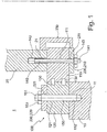
- Figur 1:
- einen Schnitt durch eine Rotorblattlagereinheit einer erfindungsgemäßen Windkraftanlage.
- FIG. 1:
- a section through a rotor blade bearing unit of a wind turbine according to the invention.
Ein Rotorblatt 20 ist üblicherweise aus einem Faserverbundwerkstoff gebildet und nach Art eines Flügels gestaltet. Zur Gewichtsersparnis ist das Rotorblatt 20 als einen inneren Hohlraum umgebende Mantelfläche ausgebildet, die an einem rückwärtigen Ende des Rotorblatts 20 in einen zylindermantelförmigen Verlauf mit einem Durchmesser von üblicherweise 2 bis 3 m übergeht. Demzufolge hat eine Ebene rückwärtige Anschlussfläche des Rotorblatts 20 einen kreisförmigen Umriss. In dieser Anschlussfläche, die auch als Anschlussflansch bezeichnet wird, sind eine Vielzahl von kranzförmig angeordneten Gewindebohrungen 21 vorgesehen, mittels denen das Rotorblatt 20 an einem Blattlager 100 befestigt ist.A
In einer Rotornabe 10 der Windkraftanlage 1 ist eine kreisförmige Anschlussfläche gebildet, die auch als Anschlussflansch bezeichnet wird, der eine kreisförmige Öffnung in der Rotornabe 10 umschließt. In dem Anschlussflansch der Rotornabe 10 ist eine Vielzahl von kranzförmig angeordneten Gewindebohrungen 11 vorgesehen.In a
Zwischen dem Anschlussflansch des Rotorblatts 20 und dem Anschlussflansch der Rotornabe 10 ist das Blattlager 100 angeordnet. Das Blattlager 100 weist zwei ringförmige, zueinander konzentrische und gegeneinander verdrehbaren Ringelemente 110, 120 auf. Ein erster Ring 110, der in dem dargestellten Ausführungsbeispiel als Innenring 110 ausgebildet ist, des Blattlagers 100 ist mittels einer Vielzahl von ersten Durchgangsbohrungen 111 des Innenrings durchsetzenden ersten Verbindungsbolzen 140 mit dem Rotorblatt 20 verbunden. Dabei sind jeweils zweite Gewindeabschnitte 142 der ersten Verbindungsbolzen 140 in die jeweiligen Gewindebohrungen 21 des Rotorblatts 20 eingeschraubt. Das Rotorblatt 20 ist mit dem Innenring 110 dadurch verbunden, dass aus dem Innenring 110 herausragende erste Gewindeabschnitte 141 der ersten Verbindungsbolzen 140 mittels Befestigungsmuttern 143 an dem Innenring 110 befestigt sind.Between the connecting flange of the
Ein zweiter Ring 110, der in dem dargestellten Ausführungsbeispiel als Außenring 120 ausgebildet ist, des Blattlagers 100 ist mittels einer Vielzahl jeweils zweite Durchgangsbohrungen 121 des Außenrings 120 durchsetzenden zweiten Verbindungsbolzen 150 mit der Rotornabe 10 verbunden. Dabei sind jeweils zweite Gewindeabschnitte 152 der zweiten Verbindungsbolzen 150 in jeweilige Gewindebohrungen 11 der Rotornabe 10 eingeschraubt. Der Außenring 120 ist mit der Rotornabe 10 dadurch verbunden, dass aus dem Außenring 120 herausragende Gewindeabschnitte 151 der zweiten Verbindungsbolzen 150 mittels Befestigungsmuttern 153 an dem Außenring 120 befestigt sind.A
Der Innenring 110 ist bezüglich des Außenrings 120 verdrehbar, wobei zwischen dem Innenring 110 und dem Außenring 120 einem Wälzkörpersatz 130 angeordnet ist. Da eine Längsachse des Rotorblatts 20 mit den Längsachsen des Innenrings 110 und des Außenrings 120 zusammenfällt, ist das Rotorblatt 20 bezüglich der Rotornabe 10 um die Längsachse des Rotorblattes 20 verdrehbar.The
Aus
Das erste Versteifungssegment 210 weist dabei Durchgangsöffnungen 211 auf, die fluchtend mit den ersten Durchgangsbohrungen 111 des Innenrings 110 ausgerichtet sind. Die jeweiligen ersten Gewindeabschnitte 141 der ersten Verbindungsbolzen 140 ragen aus dem ersten Versteifungssegment 210 heraus, und das erste Versteifungssegment 210 ist mittels Befestigungsmuttern 143 in Richtung des Innenrings 110 kraftbeaufschlagt. Folglich ist der Innenring 110 des Blattlagers 100 zwischen dem ersten Versteifungssegment 210 und dem Rotorblatt 20, im Genaueren dem Anschlussflansch des Rotorblatts 20 angeordnet.The first stiffening segment 210 in this case has through
Aus
Durch Verbinden des Rotorblatts 20 mit dem ersten Versteifungssegment 210 mittels der Klammer 230 ist ein zweiter Lastpfad gebildet, sodass auf das Rotorblatt 20 ausgeübte Kräfte nicht lediglich nur über den ersten Verbindungsbolzen 140 auf den Innenring 110 übertragen werden, sondern auch über die Klammer 230. Ferner kann, falls der Reibschluss in der Schraubverbindung beispielsweise durch verschmutzte Flanschflächen beeinträchtigt ist, der zusätzlich vorhandene Formschluss der Klammer 230 die Lastübertragung sicherstellen.By connecting the
Das zweite Versteifungssegment 220 weist Durchgangsöffnungen 221 auf, die fluchtend mit den zweiten Durchgangsbohrungen 121 des Außenrings 120 ausgerichtet sind. Die jeweiligen ersten Gewindeabschnitte 151 der zweiten Verbindungsbolzen 150 ragen aus dem zweiten Versteifungssegment 220 heraus, und das zweite Versteifungssegment 220 ist mittels Befestigungsmuttern 153 in Richtung des Außenrings 120 kraftbeaufschlagt. Folglich ist der Außenring 120 des Blattlagers 100 zwischen dem zweiten Versteifungssegment 220 und der Rotornabe 10, im Genaueren dem Anschlussflansch der Rotornabe 10 angeordnet.The second stiffening segment 220 has through
Es ist zu berücksichtigen, dass die Versteifungseinrichtung lediglich aus dem ersten Versteifungselement 210 gebildet sein kann. Ferner ist es möglich, dass die Versteifungseinrichtung aus dem ersten Versteifungssegment 210 und der Klammer 230 gebildet ist. Weiterhin ist es auch möglich, dass die Versteifungseinrichtung lediglich aus dem zweiten Versteifungssegment 220 gebildet ist. Eine optimale Wirkung der Versteifungseinrichtung wird jedoch erzielt, wenn diese sowohl das erste Versteifungssegment 210, das zweite Versteifungssegment 220 und eine Vielzahl von Klammern 230 aufweist, die jeweils mit dem ersten Versteifungssegment 210 verbunden sind.It should be noted that the stiffening device can only be formed from the first stiffening element 210. Furthermore, it is possible for the stiffening device to be formed from the first stiffening segment 210 and the
- 11
- WindkraftanlageWind turbine
- 1010
- Rotornaberotor hub
- 1111
- Gewindebohrung (der Rotornabe)Threaded hole (the rotor hub)
- 2020
- Rotorblattrotor blade
- 2121
- Gewindebohrung (des Rotorblatts)Tapping (of the rotor blade)
- 100100
- Blattlagerblade bearings
- 110110
- erster Ring / Innenring (des Blattlagers)first ring / inner ring (of the leaf bearing)
- 111111
- erste Durchgangsbohrung (des ersten Rings)first through-hole (of the first ring)
- 120120
- zweiter Ring / Außenring (des Blattlagers)second ring / outer ring (of the leaf bearing)
- 121121
- zweite Durchgangsbohrung (des zweiten Rings)second through-hole (the second ring)
- 130130
- Wälzkörpersatz / Wälzlager / Kugellager (des Blattlagers)Rolling element set / roller bearings / ball bearings (of the blade bearing)
- 140140
- erster Verbindungsbolzenfirst connecting bolt
- 141141
- (erster) Gewindeabschnitt (des ersten Verbindungsbolzens)(first) threaded portion (of the first connecting bolt)
- 142142
- (zweiter) Gewindeabschnitt (des ersten Verbindungsbolzens)(second) threaded portion (of the first connecting bolt)
- 143143
- Befestigungsmutterfixing nut
- 150150
- zweiter Verbindungsbolzensecond connecting bolt
- 151151
- (erster) Gewindeabschnitt (des zweiten Verbindungsbolzens)(first) threaded portion (of the second connecting bolt)
- 152152
- (zweiter) Gewindeabschnitt (des zweiten Verbindungsbolzens)(second) threaded portion (of the second connecting bolt)
- 153153
- Befestigungsmutterfixing nut
- 210210
- erstes Versteifungssegment / Teilringsegment / Ringsegment (der Versteifungseinrichtung)first stiffening segment / partial ring segment / ring segment (the stiffening device)
- 211211
- Durchgangsöffnung (des ersten Versteifungssegments)Through opening (of the first stiffening segment)
- 220220
- zweites Versteifungssegment / Teilringsegment / Ringsegment (der Versteifungseinrichtung)second stiffening segment / partial ring segment / ring segment (the stiffening device)
- 221221
- Durchgangsöffnung (des zweiten Versteifungssegments)Through hole (second stiffening segment)
- 230230
- Klammer (der Versteifungseinrichtung)Clamp (the stiffener)
Claims (12)
- Wind power plant (1) having a rotor hub (10), at least one blade bearing (100) and at least one rotor blade (20), the wind power plant (1) exhibiting the following features:- the blade bearing (100) exhibits a first ring (110) and a second ring (120) concentrically rotatable with respect to each other;- the first ring (110) is connected to the rotor blade (20) by means of at least one first connecting bolt (140) which penetrates a first through hole (111) of the first ring (110);- the second ring (120) is connected to the rotor hub (10) by means of at least one second connecting bolt (150) which penetrates a second through hole (121) of the second ring (120);- the wind power plant (1) exhibits at least one stiffening device (210, 220) with at least one through-opening (211, 221), through which the first connecting bolt (140) and/or the second connecting bolt (150) projects/project;- the stiffening device (210, 220) is subjected to force in direction of the blade bearing (100) by means of at least one mounting nut (143, 153), which is mounted on a thread section (141, 151) of the first connecting bolt (140) and/or of the second connecting bolt (150) projecting out of the stiffening device (210, 220)- the stiffening device (210, 220) exhibits at least one first stiffening segment (210);- the first ring (110) of said blade bearing (100) is placed between said first stiffening segment (210) and said rotor blade (20); and- the first stiffening segment (210) is subjected to force in the direction of the first ring (110) by means of a mounting nut (143),wherein the wind power plant (1) is characterized in that the stiffening device (210, 220) exhibits at least one clamp (230) which is connected to the first stiffening segment (210) and to the rotor blade (20), so that forces exerted on the rotor blade (20) can be transmitted at least partially via the clamp (230) to the first stiffening element (210).
- Wind power plant according to claim 1, characterized in that the first stiffening segment (210) is formed as a first partial ring segment (210) having a radius of curvature corresponding to a radius of curvature of the first ring (110).
- Wind power plant (1) according to one of the preceding claims, characterized in that the first stiffening segment (210) comprises a plurality of through openings (211) each in alignment with first through holes (111) of the first ring (110) and each penetrated by first connecting bolts (140).
- Wind power plant (1) according to one of the preceding claims, characterized in that the first stiffening segment (210) is designed as a first annular segment (210).
- Wind power plant (1) according to claim 4, characterized in that the first ring segment (210) has a number of through openings (211) corresponding to the number of through holes (111) in the first ring (110), each of which is in alignment with first through holes (111) of the first ring (110) and each of which is penetrated by first connecting bolts (140).
- Wind power plant (1) according to one of the preceding claims, characterized in that- the stiffening device (210, 220) comprises at least one second stiffening segment (220);- the second ring (120) of the blade bearing (100) is located between the second stiffening segment (220) and the rotor hub (10); and- the second stiffening segment (220) is subjected to force in the direction of the second ring (120) by means of a mounting nut (153).
- Wind power plant according to claim 6, characterized in that the second stiffening segment (220) is formed as a second partial ring segment (220) which exhibits a radius of curvature which corresponds to a radius of curvature of the second ring (120).
- Wind power plant (1) according to one of claims 6 to 7, characterized in that the second stiffening segment (220) exhibits a plurality of through openings (221) which are in alignment with second through holes (121) of the second ring (120) and penetrated by second connecting bolts (150).
- Wind power plant (1) according to one of claims 6 to 8, characterized in that the second stiffening segment (220) is designed as a second ring segment (220).
- Wind power plant (1) according to claim 9, characterized in that the second ring segment (220) exhibits a number of through openings (221) corresponding to the number of second through holes (121) in the second annular segment (120), each of which is in alignment with second through holes (121) of the second ring segment (120) and each of which is penetrated by second connecting bolts (150).
- Wind power plant (1) according to one of the preceding claims, characterized in that the first ring (110) is constructed as an inner ring (110) and the second ring (120) is constructed as an outer ring (120) of the blade bearing (100).
- Wind power plant (1) according to one of claims 1 to 10, characterized in that the first ring (110) is constructed as an outer ring (110) and the second ring (120) is constructed as an inner ring (120) of the blade bearing (100).
Priority Applications (1)
| Application Number | Priority Date | Filing Date | Title |
|---|---|---|---|
| PL17706468T PL3423706T3 (en) | 2016-02-29 | 2017-02-21 | Wind turbine with improved rotor blade screw connection |
Applications Claiming Priority (2)
| Application Number | Priority Date | Filing Date | Title |
|---|---|---|---|
| DE102016203269.0A DE102016203269A1 (en) | 2016-02-29 | 2016-02-29 | Wind turbine with improved rotor blade connection |
| PCT/EP2017/053932 WO2017148747A1 (en) | 2016-02-29 | 2017-02-21 | Wind turbine with improved rotor blade screw connection |
Publications (2)
| Publication Number | Publication Date |
|---|---|
| EP3423706A1 EP3423706A1 (en) | 2019-01-09 |
| EP3423706B1 true EP3423706B1 (en) | 2019-10-16 |
Family
ID=58098622
Family Applications (1)
| Application Number | Title | Priority Date | Filing Date |
|---|---|---|---|
| EP17706468.0A Active EP3423706B1 (en) | 2016-02-29 | 2017-02-21 | Wind turbine with improved rotor blade screw connection |
Country Status (5)
| Country | Link |
|---|---|
| EP (1) | EP3423706B1 (en) |
| DE (1) | DE102016203269A1 (en) |
| DK (1) | DK3423706T3 (en) |
| PL (1) | PL3423706T3 (en) |
| WO (1) | WO2017148747A1 (en) |
Families Citing this family (5)
| Publication number | Priority date | Publication date | Assignee | Title |
|---|---|---|---|---|
| CA3081889C (en) * | 2017-11-16 | 2023-12-12 | Wobben Properties Gmbh | Connection of a rotor blade to the rotor hub of a wind turbine |
| DE102017223614A1 (en) * | 2017-12-21 | 2019-06-27 | Thyssenkrupp Ag | Wind turbine, rotor system, method of using a wind turbine |
| CN109611269A (en) * | 2018-12-29 | 2019-04-12 | 华能大理风力发电有限公司 | A kind of device and Wind turbines lengthened for wind power generation unit blade |
| EP3825545B1 (en) | 2019-11-21 | 2022-06-01 | Wobben Properties GmbH | Rotor blade, rotor and wind turbine and method |
| EP3851668A1 (en) | 2020-01-17 | 2021-07-21 | Wobben Properties GmbH | Wind turbine, wind turbine rotor blade and blade bearing for a wind turbine |
Family Cites Families (7)
| Publication number | Priority date | Publication date | Assignee | Title |
|---|---|---|---|---|
| DE102005026141B4 (en) | 2005-06-06 | 2019-07-25 | Imo Momentenlager Gmbh | Wind turbine with a bearing unit for an elongated rotor blade |
| WO2007003866A1 (en) * | 2005-07-05 | 2007-01-11 | Vestas Wind Systems A/S | A wind turbine pitch bearing, and use hereof |
| DE102007008166A1 (en) * | 2007-02-14 | 2008-08-21 | Nordex Energy Gmbh | Wind energy plant with a pitch turning connection |
| DE102007008167C5 (en) * | 2007-02-14 | 2016-07-07 | Nordex Energy Gmbh | Wind turbine with a rotor hub |
| ES2423033T5 (en) * | 2007-10-01 | 2017-02-24 | Siemens Aktiengesellschaft | Step bearing for wind turbine rotor blades |
| DE102008009740A1 (en) * | 2008-02-18 | 2009-08-20 | Imo Holding Gmbh | Wind turbine and method for operating the same |
| US9551324B2 (en) * | 2013-06-20 | 2017-01-24 | General Electric Company | Pitch bearing assembly with stiffener |
-
2016
- 2016-02-29 DE DE102016203269.0A patent/DE102016203269A1/en not_active Withdrawn
-
2017
- 2017-02-21 PL PL17706468T patent/PL3423706T3/en unknown
- 2017-02-21 WO PCT/EP2017/053932 patent/WO2017148747A1/en active Application Filing
- 2017-02-21 EP EP17706468.0A patent/EP3423706B1/en active Active
- 2017-02-21 DK DK17706468.0T patent/DK3423706T3/en active
Non-Patent Citations (1)
| Title |
|---|
| None * |
Also Published As
| Publication number | Publication date |
|---|---|
| DK3423706T3 (en) | 2020-01-20 |
| EP3423706A1 (en) | 2019-01-09 |
| WO2017148747A1 (en) | 2017-09-08 |
| PL3423706T3 (en) | 2020-06-15 |
| DE102016203269A1 (en) | 2017-08-31 |
Similar Documents
| Publication | Publication Date | Title |
|---|---|---|
| EP3423706B1 (en) | Wind turbine with improved rotor blade screw connection | |
| EP2444662B2 (en) | Connection of wind turbine components | |
| EP1975405B1 (en) | Connection of elements of a wind turbine plant, use thereof and method | |
| EP3469212B1 (en) | Rotor for a wind turbine, rotor blade for a wind turbine, sleeve, and method for assembling a rotor | |
| EP2663769B1 (en) | Arrangement of components of a wind power plant | |
| EP3032093B1 (en) | Fastening device for fastening a rotor blade to a rotor hub of a wind energy plant | |
| DE19929966A1 (en) | Locking system for a bolt and a nut | |
| EP3122999B1 (en) | Annular clamping nut for a tie bar | |
| EP3938648B1 (en) | Flange connection, wind turbine having same, and method for monitoring same | |
| DE112013003905T5 (en) | Fastening device for connecting rotors of a rotary machine and method for connecting rotors | |
| EP3385558B1 (en) | Multiple disc clutch | |
| DE102010064102B4 (en) | Bearing arrangement and rolling unit for a rolling mill roll | |
| DE102017106875B4 (en) | Wind turbine and method for its assembly | |
| DE102016123370B4 (en) | Brake disc | |
| EP2474747B1 (en) | Combination of a fibre compound element and a washer element | |
| EP3074684A1 (en) | Connecting system | |
| EP3775532B1 (en) | Wind turbine rotor blade and wind turbine | |
| EP3384183A1 (en) | Planetary carrier for a transmission stage of a planetary transmission, and pre-tensioning method | |
| DE102022200534A1 (en) | Load-optimized slewing bearing arrangement | |
| EP3284960A1 (en) | Steel component for a wind turbine and wind turbine with steel component | |
| DE102013213299A1 (en) | Connecting device with a torsion-free tensionable fastener |
Legal Events
| Date | Code | Title | Description |
|---|---|---|---|
| STAA | Information on the status of an ep patent application or granted ep patent |
Free format text: STATUS: UNKNOWN |
|
| STAA | Information on the status of an ep patent application or granted ep patent |
Free format text: STATUS: THE INTERNATIONAL PUBLICATION HAS BEEN MADE |
|
| PUAI | Public reference made under article 153(3) epc to a published international application that has entered the european phase |
Free format text: ORIGINAL CODE: 0009012 |
|
| STAA | Information on the status of an ep patent application or granted ep patent |
Free format text: STATUS: REQUEST FOR EXAMINATION WAS MADE |
|
| 17P | Request for examination filed |
Effective date: 20180910 |
|
| AK | Designated contracting states |
Kind code of ref document: A1 Designated state(s): AL AT BE BG CH CY CZ DE DK EE ES FI FR GB GR HR HU IE IS IT LI LT LU LV MC MK MT NL NO PL PT RO RS SE SI SK SM TR |
|
| AX | Request for extension of the european patent |
Extension state: BA ME |
|
| GRAP | Despatch of communication of intention to grant a patent |
Free format text: ORIGINAL CODE: EPIDOSNIGR1 |
|
| STAA | Information on the status of an ep patent application or granted ep patent |
Free format text: STATUS: GRANT OF PATENT IS INTENDED |
|
| DAV | Request for validation of the european patent (deleted) | ||
| DAX | Request for extension of the european patent (deleted) | ||
| INTG | Intention to grant announced |
Effective date: 20190426 |
|
| GRAS | Grant fee paid |
Free format text: ORIGINAL CODE: EPIDOSNIGR3 |
|
| GRAA | (expected) grant |
Free format text: ORIGINAL CODE: 0009210 |
|
| STAA | Information on the status of an ep patent application or granted ep patent |
Free format text: STATUS: THE PATENT HAS BEEN GRANTED |
|
| AK | Designated contracting states |
Kind code of ref document: B1 Designated state(s): AL AT BE BG CH CY CZ DE DK EE ES FI FR GB GR HR HU IE IS IT LI LT LU LV MC MK MT NL NO PL PT RO RS SE SI SK SM TR |
|
| REG | Reference to a national code |
Ref country code: GB Ref legal event code: FG4D Free format text: NOT ENGLISH |
|
| REG | Reference to a national code |
Ref country code: CH Ref legal event code: EP |
|
| REG | Reference to a national code |
Ref country code: DE Ref legal event code: R096 Ref document number: 502017002599 Country of ref document: DE |
|
| REG | Reference to a national code |
Ref country code: IE Ref legal event code: FG4D Free format text: LANGUAGE OF EP DOCUMENT: GERMAN |
|
| REG | Reference to a national code |
Ref country code: AT Ref legal event code: REF Ref document number: 1191518 Country of ref document: AT Kind code of ref document: T Effective date: 20191115 |
|
| REG | Reference to a national code |
Ref country code: DK Ref legal event code: T3 Effective date: 20200113 |
|
| REG | Reference to a national code |
Ref country code: NL Ref legal event code: FP |
|
| REG | Reference to a national code |
Ref country code: LT Ref legal event code: MG4D |
|
| PG25 | Lapsed in a contracting state [announced via postgrant information from national office to epo] |
Ref country code: GR Free format text: LAPSE BECAUSE OF FAILURE TO SUBMIT A TRANSLATION OF THE DESCRIPTION OR TO PAY THE FEE WITHIN THE PRESCRIBED TIME-LIMIT Effective date: 20200117 Ref country code: LT Free format text: LAPSE BECAUSE OF FAILURE TO SUBMIT A TRANSLATION OF THE DESCRIPTION OR TO PAY THE FEE WITHIN THE PRESCRIBED TIME-LIMIT Effective date: 20191016 Ref country code: NO Free format text: LAPSE BECAUSE OF FAILURE TO SUBMIT A TRANSLATION OF THE DESCRIPTION OR TO PAY THE FEE WITHIN THE PRESCRIBED TIME-LIMIT Effective date: 20200116 Ref country code: LV Free format text: LAPSE BECAUSE OF FAILURE TO SUBMIT A TRANSLATION OF THE DESCRIPTION OR TO PAY THE FEE WITHIN THE PRESCRIBED TIME-LIMIT Effective date: 20191016 Ref country code: SE Free format text: LAPSE BECAUSE OF FAILURE TO SUBMIT A TRANSLATION OF THE DESCRIPTION OR TO PAY THE FEE WITHIN THE PRESCRIBED TIME-LIMIT Effective date: 20191016 Ref country code: PT Free format text: LAPSE BECAUSE OF FAILURE TO SUBMIT A TRANSLATION OF THE DESCRIPTION OR TO PAY THE FEE WITHIN THE PRESCRIBED TIME-LIMIT Effective date: 20200217 Ref country code: FI Free format text: LAPSE BECAUSE OF FAILURE TO SUBMIT A TRANSLATION OF THE DESCRIPTION OR TO PAY THE FEE WITHIN THE PRESCRIBED TIME-LIMIT Effective date: 20191016 Ref country code: BG Free format text: LAPSE BECAUSE OF FAILURE TO SUBMIT A TRANSLATION OF THE DESCRIPTION OR TO PAY THE FEE WITHIN THE PRESCRIBED TIME-LIMIT Effective date: 20200116 |
|
| PG25 | Lapsed in a contracting state [announced via postgrant information from national office to epo] |
Ref country code: RS Free format text: LAPSE BECAUSE OF FAILURE TO SUBMIT A TRANSLATION OF THE DESCRIPTION OR TO PAY THE FEE WITHIN THE PRESCRIBED TIME-LIMIT Effective date: 20191016 Ref country code: IS Free format text: LAPSE BECAUSE OF FAILURE TO SUBMIT A TRANSLATION OF THE DESCRIPTION OR TO PAY THE FEE WITHIN THE PRESCRIBED TIME-LIMIT Effective date: 20200224 Ref country code: HR Free format text: LAPSE BECAUSE OF FAILURE TO SUBMIT A TRANSLATION OF THE DESCRIPTION OR TO PAY THE FEE WITHIN THE PRESCRIBED TIME-LIMIT Effective date: 20191016 |
|
| PG25 | Lapsed in a contracting state [announced via postgrant information from national office to epo] |
Ref country code: AL Free format text: LAPSE BECAUSE OF FAILURE TO SUBMIT A TRANSLATION OF THE DESCRIPTION OR TO PAY THE FEE WITHIN THE PRESCRIBED TIME-LIMIT Effective date: 20191016 |
|
| REG | Reference to a national code |
Ref country code: DE Ref legal event code: R097 Ref document number: 502017002599 Country of ref document: DE |
|
| PG2D | Information on lapse in contracting state deleted |
Ref country code: IS |
|
| PG25 | Lapsed in a contracting state [announced via postgrant information from national office to epo] |
Ref country code: EE Free format text: LAPSE BECAUSE OF FAILURE TO SUBMIT A TRANSLATION OF THE DESCRIPTION OR TO PAY THE FEE WITHIN THE PRESCRIBED TIME-LIMIT Effective date: 20191016 Ref country code: RO Free format text: LAPSE BECAUSE OF FAILURE TO SUBMIT A TRANSLATION OF THE DESCRIPTION OR TO PAY THE FEE WITHIN THE PRESCRIBED TIME-LIMIT Effective date: 20191016 Ref country code: ES Free format text: LAPSE BECAUSE OF FAILURE TO SUBMIT A TRANSLATION OF THE DESCRIPTION OR TO PAY THE FEE WITHIN THE PRESCRIBED TIME-LIMIT Effective date: 20191016 Ref country code: CZ Free format text: LAPSE BECAUSE OF FAILURE TO SUBMIT A TRANSLATION OF THE DESCRIPTION OR TO PAY THE FEE WITHIN THE PRESCRIBED TIME-LIMIT Effective date: 20191016 Ref country code: IS Free format text: LAPSE BECAUSE OF FAILURE TO SUBMIT A TRANSLATION OF THE DESCRIPTION OR TO PAY THE FEE WITHIN THE PRESCRIBED TIME-LIMIT Effective date: 20200216 |
|
| PLBE | No opposition filed within time limit |
Free format text: ORIGINAL CODE: 0009261 |
|
| STAA | Information on the status of an ep patent application or granted ep patent |
Free format text: STATUS: NO OPPOSITION FILED WITHIN TIME LIMIT |
|
| PG25 | Lapsed in a contracting state [announced via postgrant information from national office to epo] |
Ref country code: SM Free format text: LAPSE BECAUSE OF FAILURE TO SUBMIT A TRANSLATION OF THE DESCRIPTION OR TO PAY THE FEE WITHIN THE PRESCRIBED TIME-LIMIT Effective date: 20191016 Ref country code: SK Free format text: LAPSE BECAUSE OF FAILURE TO SUBMIT A TRANSLATION OF THE DESCRIPTION OR TO PAY THE FEE WITHIN THE PRESCRIBED TIME-LIMIT Effective date: 20191016 Ref country code: IT Free format text: LAPSE BECAUSE OF FAILURE TO SUBMIT A TRANSLATION OF THE DESCRIPTION OR TO PAY THE FEE WITHIN THE PRESCRIBED TIME-LIMIT Effective date: 20191016 |
|
| 26N | No opposition filed |
Effective date: 20200717 |
|
| REG | Reference to a national code |
Ref country code: CH Ref legal event code: PL |
|
| REG | Reference to a national code |
Ref country code: DE Ref legal event code: R081 Ref document number: 502017002599 Country of ref document: DE Owner name: RWE OFFSHORE WIND GMBH, DE Free format text: FORMER OWNER: INNOGY SE, 45128 ESSEN, DE Ref country code: DE Ref legal event code: R081 Ref document number: 502017002599 Country of ref document: DE Owner name: RWE RENEWABLES GMBH, DE Free format text: FORMER OWNER: INNOGY SE, 45128 ESSEN, DE |
|
| PG25 | Lapsed in a contracting state [announced via postgrant information from national office to epo] |
Ref country code: MC Free format text: LAPSE BECAUSE OF FAILURE TO SUBMIT A TRANSLATION OF THE DESCRIPTION OR TO PAY THE FEE WITHIN THE PRESCRIBED TIME-LIMIT Effective date: 20191016 Ref country code: LU Free format text: LAPSE BECAUSE OF NON-PAYMENT OF DUE FEES Effective date: 20200221 |
|
| PG25 | Lapsed in a contracting state [announced via postgrant information from national office to epo] |
Ref country code: SI Free format text: LAPSE BECAUSE OF FAILURE TO SUBMIT A TRANSLATION OF THE DESCRIPTION OR TO PAY THE FEE WITHIN THE PRESCRIBED TIME-LIMIT Effective date: 20191016 Ref country code: LI Free format text: LAPSE BECAUSE OF NON-PAYMENT OF DUE FEES Effective date: 20200229 Ref country code: CH Free format text: LAPSE BECAUSE OF NON-PAYMENT OF DUE FEES Effective date: 20200229 |
|
| PG25 | Lapsed in a contracting state [announced via postgrant information from national office to epo] |
Ref country code: TR Free format text: LAPSE BECAUSE OF FAILURE TO SUBMIT A TRANSLATION OF THE DESCRIPTION OR TO PAY THE FEE WITHIN THE PRESCRIBED TIME-LIMIT Effective date: 20191016 Ref country code: MT Free format text: LAPSE BECAUSE OF FAILURE TO SUBMIT A TRANSLATION OF THE DESCRIPTION OR TO PAY THE FEE WITHIN THE PRESCRIBED TIME-LIMIT Effective date: 20191016 Ref country code: CY Free format text: LAPSE BECAUSE OF FAILURE TO SUBMIT A TRANSLATION OF THE DESCRIPTION OR TO PAY THE FEE WITHIN THE PRESCRIBED TIME-LIMIT Effective date: 20191016 |
|
| PG25 | Lapsed in a contracting state [announced via postgrant information from national office to epo] |
Ref country code: MK Free format text: LAPSE BECAUSE OF FAILURE TO SUBMIT A TRANSLATION OF THE DESCRIPTION OR TO PAY THE FEE WITHIN THE PRESCRIBED TIME-LIMIT Effective date: 20191016 |
|
| REG | Reference to a national code |
Ref country code: AT Ref legal event code: MM01 Ref document number: 1191518 Country of ref document: AT Kind code of ref document: T Effective date: 20220221 |
|
| PG25 | Lapsed in a contracting state [announced via postgrant information from national office to epo] |
Ref country code: AT Free format text: LAPSE BECAUSE OF NON-PAYMENT OF DUE FEES Effective date: 20220221 |
|
| REG | Reference to a national code |
Ref country code: DE Ref legal event code: R081 Ref document number: 502017002599 Country of ref document: DE Owner name: RWE OFFSHORE WIND GMBH, DE Free format text: FORMER OWNER: RWE RENEWABLES GMBH, 45145 ESSEN, DE |
|
| P01 | Opt-out of the competence of the unified patent court (upc) registered |
Effective date: 20230530 |
|
| PGFP | Annual fee paid to national office [announced via postgrant information from national office to epo] |
Ref country code: NL Payment date: 20240220 Year of fee payment: 8 Ref country code: IE Payment date: 20240216 Year of fee payment: 8 |
|
| PGFP | Annual fee paid to national office [announced via postgrant information from national office to epo] |
Ref country code: DE Payment date: 20240216 Year of fee payment: 8 Ref country code: GB Payment date: 20240222 Year of fee payment: 8 |
|
| PGFP | Annual fee paid to national office [announced via postgrant information from national office to epo] |
Ref country code: PL Payment date: 20240215 Year of fee payment: 8 Ref country code: FR Payment date: 20240222 Year of fee payment: 8 Ref country code: DK Payment date: 20240221 Year of fee payment: 8 Ref country code: BE Payment date: 20240219 Year of fee payment: 8 |