EP3423115B1 - Apparatus for opaque fluid disinfection with ultraviolet emission - Google Patents
Apparatus for opaque fluid disinfection with ultraviolet emission Download PDFInfo
- Publication number
- EP3423115B1 EP3423115B1 EP17716994.3A EP17716994A EP3423115B1 EP 3423115 B1 EP3423115 B1 EP 3423115B1 EP 17716994 A EP17716994 A EP 17716994A EP 3423115 B1 EP3423115 B1 EP 3423115B1
- Authority
- EP
- European Patent Office
- Prior art keywords
- chamber
- tube
- reactor
- baffle
- baffles
- Prior art date
- Legal status (The legal status is an assumption and is not a legal conclusion. Google has not performed a legal analysis and makes no representation as to the accuracy of the status listed.)
- Active
Links
Images



Classifications
-
- A—HUMAN NECESSITIES
- A61—MEDICAL OR VETERINARY SCIENCE; HYGIENE
- A61L—METHODS OR APPARATUS FOR STERILISING MATERIALS OR OBJECTS IN GENERAL; DISINFECTION, STERILISATION OR DEODORISATION OF AIR; CHEMICAL ASPECTS OF BANDAGES, DRESSINGS, ABSORBENT PADS OR SURGICAL ARTICLES; MATERIALS FOR BANDAGES, DRESSINGS, ABSORBENT PADS OR SURGICAL ARTICLES
- A61L2/00—Disinfection or sterilisation of materials or objects, in general; Accessories therefor
- A61L2/02—Disinfection or sterilisation of materials or objects, in general; Accessories therefor using physical processes
- A61L2/08—Radiation
- A61L2/10—Ultraviolet [UV] radiation
-
- C—CHEMISTRY; METALLURGY
- C02—TREATMENT OF WATER, WASTE WATER, SEWAGE, OR SLUDGE
- C02F—TREATMENT OF WATER, WASTE WATER, SEWAGE, OR SLUDGE
- C02F1/00—Treatment of water, waste water, or sewage
- C02F1/30—Treatment of water, waste water, or sewage by irradiation
- C02F1/32—Treatment of water, waste water, or sewage by irradiation with ultraviolet light
- C02F1/325—Irradiation devices or lamp constructions
-
- C—CHEMISTRY; METALLURGY
- C02—TREATMENT OF WATER, WASTE WATER, SEWAGE, OR SLUDGE
- C02F—TREATMENT OF WATER, WASTE WATER, SEWAGE, OR SLUDGE
- C02F2201/00—Apparatus for treatment of water, waste water or sewage
- C02F2201/32—Details relating to UV-irradiation devices
- C02F2201/322—Lamp arrangement
- C02F2201/3227—Units with two or more lamps
-
- C—CHEMISTRY; METALLURGY
- C02—TREATMENT OF WATER, WASTE WATER, SEWAGE, OR SLUDGE
- C02F—TREATMENT OF WATER, WASTE WATER, SEWAGE, OR SLUDGE
- C02F2201/00—Apparatus for treatment of water, waste water or sewage
- C02F2201/32—Details relating to UV-irradiation devices
- C02F2201/324—Lamp cleaning installations, e.g. brushes
Definitions
- transmittance in optics and spectroscopy, is the fraction of light incident at a given wavelength that crosses a sample.
- the invention is an apparatus and a method for the sanification/sterilization of opaque fluids by means of ultraviolet radiation; in other words, the invention is set to abate the bacterial load also in those opaque fluids that are hard to treat with UV rays, due to the fact that they have low values of transmittance, where with "low values of transmittance" it is intended fluids having transmittance even lower than 1%.
- the treatment method has effective use in the reduction of the bacterial load of milk whey, i.e. the liquid part of milk that is separated from the curd during cheese-making.
- WO9222502 discloses a reactor including a UV radiation lamp.
- the lamp is positioned in the reactor within a transparent sheath, wherein a plurality of baffles are secured to the inside surface of the outer wall, each baffle is circular shaped with a central opening which provides clearance for the protective sheath as well as the system generally designated for cleaning the protective sheath.
- the baffles are provided within the annular chamber to induce turbulence in the flow to ensure adequate mixing so that during the residence time for the aqueous media all portions thereof are exposed to the UV radiation from lamp to ensure the desired treatment for the aqueous media.
- One object of the present invention is to provide the art with an apparatus for treating opaque fluids in the scope of a simple, rational solution with rather limited cost.
- the invention refers to a system for conveying the fluid to be sanified, which ensures the maximum performance and effectiveness of treatment for the fluid to be treated.
- the apparatus for opaque fluid disinfection with ultraviolet emission can comprise at least one reactor chamber, within which an ultraviolet light source is protected inside a quartz tube. At least one portion of the quartz tube is coaxially inserted in a jacket of larger size, and the fluid to be treated passes into the space defined between said tube of larger size and said quartz tube.
- the above-indicated treatment device is part of a set equipment piece which provides for means for adhering the tubes and the interior of the chamber of the reactor, such means acting as a mechanical cleaning system.
- the invention also claims the process of treating milk whey adapted to obtain a bactericide effect, by creating a thin and continuous annular flow of opaque fluid, supplying the UV radiation from within said created annular flow.
- the separation means between UV irradiation source and the thin and continuous flow of opaque fluid is constituted by quartz.
- the thickness of the annular passage i.e. of the annular interspace, is preferably in the interval comprised between 3 and 6 millimeters, preferably 4 or 5 millimeters.
- the invention is set to create a "self-managed" cleaning system by means of the reciprocating translation of the means adapted to create the thin annular flow and providing for scraping rings.
- reference number 1 overall indicates an apparatus for treating opaque fluids according to the invention.
- the apparatus 1 comprises a reactor body 2C in which a reactor chamber 2 is defined, in more detail a hollow cylindrical body that is closed at the ends 2A, 2B.
- a reactor chamber 2 is defined, in more detail a hollow cylindrical body that is closed at the ends 2A, 2B.
- the cylindrical reactor chamber 2 is closed at the longitudinal ends 2A, 2B by a first and a second terminal respectively provided with an inlet port 4A from which a fluid to be treated enters and with an outlet port 4B) from which the treated fluid exits from the reactor chamber 2.
- Said reactor chamber 2 comprises a tube bundle therein ( FIG. 4 ) constituted by tubes 3, preferably made of quartz, in turn containing a germicidal lamp 21 UV. Therefore, the group of tubes 3 is fixed and longitudinally arranged inside the reactor body; analogously, also the lamps 21 are fixed.
- the reactor body 2 therefore receives the fluid to be treated through an inlet port 4A; the fluid, after having been treated as described hereinbelow, exits from the reactor body 2 from the outlet port 4B.
- AA indicates the axis of the cylindrical reactor body 2.
- the series of quartz tubes 3 are at a certain distance from each other; specifically, with respect to the cross section, eight tubes are observed, and it follows that they are at 45° with respect to each other arranged along the entire circular section of the reactor chamber 2; nevertheless, it is specified that the protection is not limited by the number or size or power of the lamps 21 and tubes 3.
- the tubes are uniformly distributed around the longitudinal extension axis of the reactor chamber 2.
- the UV lamps 21 are situated within each quartz tube; the fluid however (which is opaque, with low transmittance, and preferably milk whey) passes inside the chamber 2 and externally with respect to the tubes 3.
- the reactor chamber 2 is equipped with a movable scraper 5, also defined hereinbelow as a movable group ( fig. 9 ).
- the movable scraper 5 is constituted by a plurality of sub-chambers 6, also defined as treatment chambers, arranged at the interior thereof. Even if hereinbelow a movable group 5 is described with a plurality of sub-chambers 6 associated therewith, the invention can also be intended as already defined with a single sub-chamber (hence the movable group 5 can be a single sub-chamber 6).
- the movable scraper 5 can be extended for an overall length smaller than the internal length of one or more quartz tubes, i.e. than the interior of the reactor chamber 2.
- the movable scraper 5 comprises at least one pair of cleaning baffles 7.
- a pair of cleaning baffles 7 delimits a sub-chamber 6 in the reactor chamber 2.
- the sub-chamber 6 can identify a treatment area 17, better described hereinbelow, whose length L is smaller than the length L1 of the treatment chamber 6.
- the sub-chambers 6 are defined (and divided from each other) by a pair of cleaning baffles 7, laterally arranged with respect to the treatment area (i.e. upstream and downstream with respect to the fluid flow). It follows that the length of the treatment area 17 is smaller than the distance between said cleaning baffles 7.
- a multiplicity of sub-chambers 6 are present inside the reactor chamber 2; in turn such sub-chambers are defined by at least one treatment area 17 ( fig. 9 and fig. 10 ). Therefore, the sub-chambers 6, as illustrated, are connected to each other and divided by the respective cleaning baffles 7 so as to preferably form the movable scraper 5: in the embodiment, one observes four cleaning baffles 7, two at the ends and two central baffles, for operating in three sub-chambers 6.
- the apparatus comprises a plurality of tube holder baffles 8, each tube holder baffle 8 supporting a respective tubular jacket 9 and dividing a respective sub-chamber 6 delimitated by a pair of cleaning baffles 7.
- the longitudinal extension L of the jacket 9 can be smaller than the distance L1 between a pair of cleaning baffles defining the sub-chamber space 6.
- each sub-chamber 6 can also comprises, at its interior, a further baffle that is indicated as tube holder baffle 8 and respective conveyance jackets 9.
- the apparatus 1 can comprise, inside the reactor chamber 2, a tube holder baffle and a tubular jacket 9 supported by the tube holder baffle 8.
- the movable scraper 5 can comprise the tube holder baffle 8.
- the baffle 8 is substantially a discoid element, arranged transversely to the axis AA of the chamber 2; in addition, it has size substantially equal to the interior of the reactor chamber 2, as better specified hereinbelow.
- the cleaning baffles 7 can be discoid elements arranged as the tube holder baffles 8.
- Each tube holder baffle 8 is adapted to divide, into two parts 6A, 6B, the relative treatment area 17 and hence also the treatment chamber 6.
- Each tube holder baffle 8 is also adapted to support the series of tubular jackets 9; in such a manner, each jacket 9, which has size greater than that of the quartz tubes 3, can be maintained coaxial with the respective quartz tube 3 such that the difference of diameter between said elements 3 and 9 comes to define an annular interspace 20, of thin thickness, within which the fluid to be treated passes. From this, there is the definition of thin film thickness as intended by the present invention.
- the times of effective treatment of the opaque fluid with the UV light source is limited to the passage inside the interspace created between the external jacket 9 (also described as tube hereinbelow) and the fixed quartz tube 3.
- annular interspace 20 between the tube 3 and the jacket 9 allows the passage of the fluid to be treated through the tube holder baffle 8.
- the opaque fluid that enters into the reactor body 2 is introduced into the treatment chamber 6, i.e. it passes from one treatment chamber to the other, through a series of holes 10 made on the cleaning baffles 7.
- the fluid once it has entered into the first section 6A of the treatment chamber 6, is forced by the tube holder baffle 8 to travel along one of the interspaces 20 before then passing into the other half 6B of the treatment chamber, and exits from the holes 10 of the opposite cleaning baffle 7.
- the tube holder baffle 8 incorporates a sealing system adapted to limit, as much as possible, the by-pass in the area adjacent to the walls of the reactor chamber 2; said sealing system is attained with a series of sliding blocks 11, arranged on the periphery of the baffle 8, kept adherent to the internal wall of the reactor with springs 12; the sliding blocks 11 adhere and slide on the internal wall of the reactor body 2.
- the assembly thus constituted i.e. that which was also defined as the movable scraper 5, has smaller length than the entire length of the reactor body 2C.
- said scraper 5 is housed inside the chamber 2 by means of longitudinally arranged support guides 12 fixed to the two bottom ends 2A and 2B of said reactor chamber 2.
- the scraper 5 is reversibly translatable along the axis AA by means of a cylinder 13 and relative stem (not illustrated) connected to said group 5.
- the group 5 slides on said support guides 12 which are inserted in respective holes 14 made on all the baffles 7 and 8 of the group 5.
- the movement of the movable scraper 5 occurs as stated by means of a piston and cylinder; nevertheless, without departing from the protective scope, such movement can also be actuated by means of an electric actuator.
- all the cleaning baffles 7 comprise - in addition to the plurality of holes 10 of limited size for the passage of the product to be treated and in addition to the aforesaid holes 14 - a series of holes 15 each of which comprising spring-loaded adherence rings 16 that are integral with the cleaning baffle 7 in contact with the relative quartz tube 3 that crosses it.
- each adherence ring 16 scrapes and cleans the relative quartz tube 3.
- the movable scraper 5 can also correspond, as stated above, with only one sub-chamber 6.
- That described above constitutes a first cleaning system "self-managed" by the movable scraper 5, upon its reciprocating movement inside the chamber 2; indeed, this occurs by means of the cleaning baffles 7 and the scraping rings 16 which are moved for the cleaning.
- the reactor 1 also provides for a second cleaning system, with which the dead areas not reachable by the scraping rings 16 are cleaned.
- the exterior of the chamber 2 i.e. the external casing
- the tubes 3 are parallel to each other and equidistant with respect to the longitudinal extension axis of the reactor chamber 2. More preferably, the tubes 3 are uniformly distributed around said longitudinal extension axis.
- the movable scraper In operating configuration, the movable scraper is situated in the middle of the reactor: the fluid enters at one end, passes through the first cleaning baffle, specifically through a plurality of its holes made on most of the baffle-disc. It is observed that the interspace 20 defines the only passage for the fluid through said tube holder baffle 8.
- the fluid arrives into the first sub-chamber and is forcibly conveyed to pass through the plurality of passage interspaces 20 obtained from the series of jacket segments 9 coaxial with the quartz tubes 3 (the latter extended over the entire length of the cylinder reactor).
- the treated fluid then continues through the second cleaning baffle and continues into the adjacent sub-chamber and hence treatment area and so forth until reaching the final area of the chamber 2, from where it is drawn in order to continue into the various lines downstream.
- the actuation of the cleaning system for the baffles occurs by alternately translating the movable scraper 5 inside the reactor chamber 2, and possibly by actuating the external cleaning system with blade jets.
- the apparatus 1 for opaque fluid disinfection with ultraviolet emission at least one portion of the quartz tube is coaxially inserted in a tube jacket of larger size, and the fluid to be treated passes into the space defined between said tube of larger size and said quartz tube.
Landscapes
- Health & Medical Sciences (AREA)
- Life Sciences & Earth Sciences (AREA)
- Hydrology & Water Resources (AREA)
- Engineering & Computer Science (AREA)
- General Health & Medical Sciences (AREA)
- Public Health (AREA)
- Veterinary Medicine (AREA)
- Toxicology (AREA)
- Epidemiology (AREA)
- Animal Behavior & Ethology (AREA)
- Environmental & Geological Engineering (AREA)
- Water Supply & Treatment (AREA)
- Chemical & Material Sciences (AREA)
- Organic Chemistry (AREA)
- Cleaning In General (AREA)
- Physical Water Treatments (AREA)
Description
- The present finding is inserted in the field of processes and systems for treating opaque fluids, fluids with low transmittance. It is briefly recalled that transmittance, in optics and spectroscopy, is the fraction of light incident at a given wavelength that crosses a sample.
- The invention is an apparatus and a method for the sanification/sterilization of opaque fluids by means of ultraviolet radiation; in other words, the invention is set to abate the bacterial load also in those opaque fluids that are hard to treat with UV rays, due to the fact that they have low values of transmittance, where with "low values of transmittance" it is intended fluids having transmittance even lower than 1%.
- In particular, the treatment method has effective use in the reduction of the bacterial load of milk whey, i.e. the liquid part of milk that is separated from the curd during cheese-making.
-
WO9222502 - The laws relative to industrial production, the increased general interest and the evolution of strains of resistant bacteria all necessitate an effective application of alternative treatment/disinfection methods, such as treatment with UV.
- However, opaque fluids render the currently-known treatments and the action of UV lamps little effective.
- One example of an apparatus for treatment by means of UV is described in
US 5,874,740 . In such document, an apparatus is described in which a plurality of UV tubes are provided with a scraper ring for cleaning the tubes themselves. The scraper rings are in contact with the surface of the tubes due to the presence of O-ring gaskets, and at their interior they define a chamber into which phosphoric acid is injected for cleaning the tube. - Other examples of similar apparatuses are described:
WO 2011/014944 ,EP 2 792 371WO 2011/026619 andEP 1 882 521 . - One object of the present invention is to provide the art with an apparatus for treating opaque fluids in the scope of a simple, rational solution with rather limited cost.
- These and other objects are attained due to the characteristics of the invention reported in independent claim 1. The dependent claims delineate preferred and/or particularly advantageous aspects of the invention.
- In accordance with the aforesaid objects, the invention refers to a system for conveying the fluid to be sanified, which ensures the maximum performance and effectiveness of treatment for the fluid to be treated.
- In one formulation of the present finding, the apparatus for opaque fluid disinfection with ultraviolet emission can comprise at least one reactor chamber, within which an ultraviolet light source is protected inside a quartz tube. At least one portion of the quartz tube is coaxially inserted in a jacket of larger size, and the fluid to be treated passes into the space defined between said tube of larger size and said quartz tube.
- Due to this solution, a sanifying bactericide effect is ensured, by acting on a thin and continuous annular flow of opaque fluid.
- In addition, and in accordance with one characteristic of the present invention, the above-indicated treatment device is part of a set equipment piece which provides for means for adhering the tubes and the interior of the chamber of the reactor, such means acting as a mechanical cleaning system.
- Due to this solution, it is possible to remove, only with the movement of the movable treatment group, the deposits/residues from the quartz tubes, avoiding manual cleaning.
- In addition, this always ensures the maximum UV transmittance of the plant.
- As stated, the invention also claims the process of treating milk whey adapted to obtain a bactericide effect, by creating a thin and continuous annular flow of opaque fluid, supplying the UV radiation from within said created annular flow. The separation means between UV irradiation source and the thin and continuous flow of opaque fluid is constituted by quartz.
- Due to this solution, significant abatement of the bacterial load was verified, even at high flow rate levels. In the following table, the abatements measured on enterobacteria and total bacterial load at 30°C are recorded.

- The thickness of the annular passage, i.e. of the annular interspace, is preferably in the interval comprised between 3 and 6 millimeters, preferably 4 or 5 millimeters.
- Finally, the invention is set to create a "self-managed" cleaning system by means of the reciprocating translation of the means adapted to create the thin annular flow and providing for scraping rings.
- Said objects and advantages are all attained by the apparatus for opaque fluid disinfection with ultraviolet emission, object of the present invention, which is characterized for that provided in the below-reported claims.
- This and other characteristics will be clearer from the following description of several embodiments illustrated, merely by way of a non-limiting example, in the enclosed drawing tables.
-
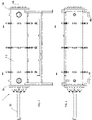
Figures 1 and 2 : illustrate an external view of the apparatus constituted by a reactor chamber, -
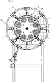
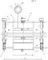
Figures 3 and4 : illustrate two views, of which one is sectioned with detail of the washing system with pressurized water, -
Figures 5, 6 ,7, 8 : illustrate four views of the movable group, -
Figure 9 : illustrates only the movable group in an axonometric view thereof, -
Figure 10 : illustrates only one treatment chamber in detail, -
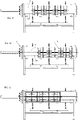
Figures 11, 12, 13 : illustrate the apparatus with the movable group therein and positioned according to three possible configurations thereof, wherein the first configuration corresponds to the normal treatment position on the opaque fluid while the other two configurations depict the right and left limit positions given by the reciprocating movement in order to self-induce the cleaning of the tubes by means of respective scraping rings. - With particular reference to the above-indicated figures, reference number 1 overall indicates an apparatus for treating opaque fluids according to the invention.
- The apparatus 1 comprises a reactor body 2C in which a
reactor chamber 2 is defined, in more detail a hollow cylindrical body that is closed at theends 2A, 2B. Preferably, thecylindrical reactor chamber 2 is closed at thelongitudinal ends 2A, 2B by a first and a second terminal respectively provided with an inlet port 4A from which a fluid to be treated enters and with anoutlet port 4B) from which the treated fluid exits from thereactor chamber 2. - Said
reactor chamber 2 comprises a tube bundle therein (FIG. 4 ) constituted bytubes 3, preferably made of quartz, in turn containing agermicidal lamp 21 UV. Therefore, the group oftubes 3 is fixed and longitudinally arranged inside the reactor body; analogously, also thelamps 21 are fixed. - The
reactor body 2 therefore receives the fluid to be treated through an inlet port 4A; the fluid, after having been treated as described hereinbelow, exits from thereactor body 2 from theoutlet port 4B. - For the sake of simplicity, AA indicates the axis of the
cylindrical reactor body 2. - The series of
quartz tubes 3 are at a certain distance from each other; specifically, with respect to the cross section, eight tubes are observed, and it follows that they are at 45° with respect to each other arranged along the entire circular section of thereactor chamber 2; nevertheless, it is specified that the protection is not limited by the number or size or power of thelamps 21 andtubes 3. In one embodiment, the tubes are uniformly distributed around the longitudinal extension axis of thereactor chamber 2. - Returning to the description, it is recalled that the
UV lamps 21 are situated within each quartz tube; the fluid however (which is opaque, with low transmittance, and preferably milk whey) passes inside thechamber 2 and externally with respect to thetubes 3. - The
reactor chamber 2 is equipped with amovable scraper 5, also defined hereinbelow as a movable group (fig. 9 ). According to one aspect of the invention, themovable scraper 5 is constituted by a plurality ofsub-chambers 6, also defined as treatment chambers, arranged at the interior thereof. Even if hereinbelow amovable group 5 is described with a plurality ofsub-chambers 6 associated therewith, the invention can also be intended as already defined with a single sub-chamber (hence themovable group 5 can be a single sub-chamber 6). - Continuing with more detail, the
movable scraper 5 can be extended for an overall length smaller than the internal length of one or more quartz tubes, i.e. than the interior of thereactor chamber 2. - According to one aspect of the invention, the
movable scraper 5 comprises at least one pair ofcleaning baffles 7. Preferably, a pair ofcleaning baffles 7 delimits asub-chamber 6 in thereactor chamber 2. - The
sub-chamber 6 can identify atreatment area 17, better described hereinbelow, whose length L is smaller than the length L1 of thetreatment chamber 6. - In more detail, the
sub-chambers 6 are defined (and divided from each other) by a pair ofcleaning baffles 7, laterally arranged with respect to the treatment area (i.e. upstream and downstream with respect to the fluid flow). It follows that the length of thetreatment area 17 is smaller than the distance between saidcleaning baffles 7. - In general and as indicated in the enclosed tables, in order to optimize the treatment process, a multiplicity of
sub-chambers 6 are present inside thereactor chamber 2; in turn such sub-chambers are defined by at least one treatment area 17 (fig. 9 andfig. 10 ). Therefore, thesub-chambers 6, as illustrated, are connected to each other and divided by therespective cleaning baffles 7 so as to preferably form the movable scraper 5: in the embodiment, one observes fourcleaning baffles 7, two at the ends and two central baffles, for operating in threesub-chambers 6. - According to one aspect of the invention, the apparatus comprises a plurality of
tube holder baffles 8, eachtube holder baffle 8 supporting a respectivetubular jacket 9 and dividing arespective sub-chamber 6 delimitated by a pair ofcleaning baffles 7. - The longitudinal extension L of the
jacket 9 can be smaller than the distance L1 between a pair of cleaning baffles defining thesub-chamber space 6. - According to one aspect of the invention, each sub-chamber 6 can also comprises, at its interior, a further baffle that is indicated as
tube holder baffle 8 andrespective conveyance jackets 9. - In other words, the apparatus 1 can comprise, inside the
reactor chamber 2, a tube holder baffle and atubular jacket 9 supported by thetube holder baffle 8. Themovable scraper 5 can comprise thetube holder baffle 8. - The
baffle 8 is substantially a discoid element, arranged transversely to the axis AA of thechamber 2; in addition, it has size substantially equal to the interior of thereactor chamber 2, as better specified hereinbelow. - Also the cleaning baffles 7 can be discoid elements arranged as the tube holder baffles 8.
- Each
tube holder baffle 8 is adapted to divide, into twoparts relative treatment area 17 and hence also thetreatment chamber 6. - Each
tube holder baffle 8 is also adapted to support the series oftubular jackets 9; in such a manner, eachjacket 9, which has size greater than that of thequartz tubes 3, can be maintained coaxial with therespective quartz tube 3 such that the difference of diameter between saidelements annular interspace 20, of thin thickness, within which the fluid to be treated passes. From this, there is the definition of thin film thickness as intended by the present invention. - In such a manner, the times of effective treatment of the opaque fluid with the UV light source is limited to the passage inside the interspace created between the external jacket 9 (also described as tube hereinbelow) and the fixed
quartz tube 3. - In other words, the
annular interspace 20 between thetube 3 and thejacket 9 allows the passage of the fluid to be treated through thetube holder baffle 8. - The opaque fluid that enters into the
reactor body 2 is introduced into thetreatment chamber 6, i.e. it passes from one treatment chamber to the other, through a series ofholes 10 made on the cleaning baffles 7. - The fluid, once it has entered into the
first section 6A of thetreatment chamber 6, is forced by thetube holder baffle 8 to travel along one of theinterspaces 20 before then passing into theother half 6B of the treatment chamber, and exits from theholes 10 of theopposite cleaning baffle 7. - In more detail, the
tube holder baffle 8 incorporates a sealing system adapted to limit, as much as possible, the by-pass in the area adjacent to the walls of thereactor chamber 2; said sealing system is attained with a series of slidingblocks 11, arranged on the periphery of thebaffle 8, kept adherent to the internal wall of the reactor withsprings 12; the slidingblocks 11 adhere and slide on the internal wall of thereactor body 2. - As stated, the assembly thus constituted, i.e. that which was also defined as the
movable scraper 5, has smaller length than the entire length of the reactor body 2C. - Due to such configuration, said
scraper 5 is housed inside thechamber 2 by means of longitudinally arranged support guides 12 fixed to the two bottom ends 2A and 2B of saidreactor chamber 2. - More precisely, the
scraper 5 is reversibly translatable along the axis AA by means of acylinder 13 and relative stem (not illustrated) connected to saidgroup 5. Thegroup 5 slides on said support guides 12 which are inserted inrespective holes 14 made on all thebaffles group 5. - In the embodiment, the movement of the
movable scraper 5 occurs as stated by means of a piston and cylinder; nevertheless, without departing from the protective scope, such movement can also be actuated by means of an electric actuator. - In accordance with one embodiment, it is observed that all the cleaning baffles 7 comprise - in addition to the plurality of
holes 10 of limited size for the passage of the product to be treated and in addition to the aforesaid holes 14 - a series ofholes 15 each of which comprising spring-loaded adherence rings 16 that are integral with the cleaningbaffle 7 in contact with therelative quartz tube 3 that crosses it. In such a manner, by moving the group 5 (by means of activation of the cylinder 13), eachadherence ring 16 scrapes and cleans therelative quartz tube 3. Themovable scraper 5 can also correspond, as stated above, with only onesub-chamber 6. - As stated, due to this solution it is possible to remove, only with the movement of the scraper, the deposits/residues from the quartz tubes, avoiding manual cleaning.
- That described above constitutes a first cleaning system "self-managed" by the
movable scraper 5, upon its reciprocating movement inside thechamber 2; indeed, this occurs by means of the cleaning baffles 7 and the scraping rings 16 which are moved for the cleaning. - In accordance with possible embodiments, the reactor 1 also provides for a second cleaning system, with which the dead areas not reachable by the scraping rings 16 are cleaned.
- In more detail and with reference to the figures, it is observed that the exterior of the
chamber 2, i.e. the external casing, is equipped with rings ofnozzles 18, which traverse the skirt of the chamber and are connected to a fluid source so as to direct a blade jet of water under pressure towards the interior and hit, also following the movement of thegroup 5, the hidden areas in proximity to thebaffles - Naturally, the aforesaid external cleaning system with pressurized water occurs under vacuum conditions, i.e. with reactor lacking the fluid to be treated.
- Preferably, the
tubes 3 are parallel to each other and equidistant with respect to the longitudinal extension axis of thereactor chamber 2. More preferably, thetubes 3 are uniformly distributed around said longitudinal extension axis. - In operating configuration, the movable scraper is situated in the middle of the reactor: the fluid enters at one end, passes through the first cleaning baffle, specifically through a plurality of its holes made on most of the baffle-disc. It is observed that the
interspace 20 defines the only passage for the fluid through saidtube holder baffle 8. - Then, the fluid arrives into the first sub-chamber and is forcibly conveyed to pass through the plurality of passage interspaces 20 obtained from the series of
jacket segments 9 coaxial with the quartz tubes 3 (the latter extended over the entire length of the cylinder reactor). - The treated fluid then continues through the second cleaning baffle and continues into the adjacent sub-chamber and hence treatment area and so forth until reaching the final area of the
chamber 2, from where it is drawn in order to continue into the various lines downstream. - The actuation of the cleaning system for the baffles occurs by alternately translating the
movable scraper 5 inside thereactor chamber 2, and possibly by actuating the external cleaning system with blade jets. - In such a manner, in the apparatus 1 for opaque fluid disinfection with ultraviolet emission, at least one portion of the quartz tube is coaxially inserted in a tube jacket of larger size, and the fluid to be treated passes into the space defined between said tube of larger size and said quartz tube.
Claims (17)
- Apparatus (1) for opaque fluid disinfection by means of ultraviolet emission, the apparatus comprising:• a reactor body (2C), in which a cylindrical reactor chamber (2) is defined, closed at the longitudinal ends by a first and a second terminal respectively provided with an inlet port (4A) from which a fluid to be treated enters and with an outlet port (4B) from which the treated fluid exits from the reactor chamber (2);• at least one ultraviolet light source housed in a tube (3) longitudinally extended inside the reactor chamber (2);said apparatus (1) being characterized in that it comprises, inside the reactor chamber (2):• a tube holder baffle (8) comprising a sealing system in the area adjacent to the internal walls of the reactor body (2C), and• a tubular jacket (9) supported by said tube holder baffle (8), said jacket (9) being coaxial with the tube (3) and having larger size with respect to the latter so as to define an annular interspace (20) between the tube (3) and the jacket (9) in a manner such to allow the passage of the fluid to be treated through the tube holder baffle (8), where said interspace (20) defines the only passage of the fluid to be treated through the tube holder baffle (8).
- Apparatus according to claim 1, wherein said apparatus comprises a movable scraper (5) translatable along the longitudinal extension of the reactor chamber (2), inside the same, said movable scraper (5) comprising at least one pair of cleaning baffles (7).
- Apparatus according to claim 1 or 2, wherein said sealing system comprises a series of sliding blocks (11), arranged on the periphery of the baffle (8), said sliding blocks being kept adherent to the internal wall of the reactor with springs (12), and adapted to slide on the internal wall of the reactor chamber (2) following the translation of the movable scraper (5).
- Apparatus according to claim 2 or 3, when dependent on claim 2, wherein each baffle (7) has:a. a series of holes (10) adapted to allow the passage of the fluid to be treated through said baffle (7),b. at least one hole (15) for the passage of said tube (3), said hole (15) being associated with a spring-loaded adherence ring (16), which remains in contact with the tube (3) and is adapted to scrape and clean it following the translation of the movable scraper (5).
- Apparatus according to claim 4, wherein said apparatus comprises a plurality of tube holder baffles (8), each tube holder baffle (8) supporting a respective tubular jacket (9) and dividing a respective sub-chamber (6) delimited by a pair of cleaning baffles (7).
- Apparatus according to claim 5, wherein the longitudinal extension (L) of the jacket (9) is less than the distance (L1) between a pair of baffles defining the sub-chamber (6).
- Apparatus according to one of claims 2 to 6, wherein said movable scraper (5) has smaller length than the entire length of the reactor body and is housed inside the chamber (2) by means of longitudinally arranged support guides (19) fixed to the terminals (2A) and (2B) of said reactor body (2C).
- Apparatus according to one of claims 2 to 7, wherein said movable scraper (5) is reversibly translatable along an axis (AA) of the reactor body (2C), the movement of the movable scraper (5) occurring by means of a cylinder (13) and relative stem connected to the movable scraper (5) or by means of an electric actuator.
- Apparatus according to one of claims 7 to 8, wherein the movable scraper (5) slides on said support guides (19) which are inserted in respective holes (14) formed on the baffles (7) and on the tube holder baffle(s) (8).
- Apparatus according to claim 4 or one of claims 5 to 9 when dependent on claim 4, comprising at least three baffles (7) which define a pair of sub-chambers (6), wherein said sub-chambers (6) are connected to each other and divided by the respective baffles (7).
- Apparatus according to one of the preceding claims, comprising an external washing system comprising a plurality of nozzles (18) which direct a blade jet of water under pressure towards the interior of the reactor chamber (2).
- Apparatus according to one of the preceding claims, wherein the reactor chamber (2) comprises a tube bundle therein constituted by a plurality of tubes (3) in turn containing a respective germicidal lamp (21), tubes (3) and lamps (21) being fixed.
- Apparatus according to claim 12, wherein said tubes (3) are parallel to each other and equidistant with respect to the longitudinal extension axis of the reactor chamber (2).
- Apparatus according to claim 13, wherein said tubes (3) are uniformly distributed around said longitudinal extension axis.
- Apparatus according to one of the preceding claims, wherein said tube (3) is made of quartz.
- Apparatus according to one of the preceding claims, wherein said movable scraper (5) can be associated in at least one sub-chamber (6) which identifies a treatment area (17), said sub-chamber (6) being divided into two parts (6A, 6B) by said tube holder baffle (8).
- Apparatus according to one of the preceding claims, wherein the thickness of said annular interspace (20) is comprised in the interval between 3 and 6 millimeters.
Applications Claiming Priority (2)
| Application Number | Priority Date | Filing Date | Title |
|---|---|---|---|
| ITUA2016A001331A ITUA20161331A1 (en) | 2016-03-03 | 2016-03-03 | METHOD AND DISINFECTION SYSTEM MATT FLUIDS WITH ULTRAVIOLET EMISSION |
| PCT/IB2017/051242 WO2017149501A1 (en) | 2016-03-03 | 2017-03-03 | Apparatus for opaque fluid disinfection with ultraviolet emission |
Publications (2)
| Publication Number | Publication Date |
|---|---|
| EP3423115A1 EP3423115A1 (en) | 2019-01-09 |
| EP3423115B1 true EP3423115B1 (en) | 2022-10-12 |
Family
ID=56203475
Family Applications (1)
| Application Number | Title | Priority Date | Filing Date |
|---|---|---|---|
| EP17716994.3A Active EP3423115B1 (en) | 2016-03-03 | 2017-03-03 | Apparatus for opaque fluid disinfection with ultraviolet emission |
Country Status (3)
| Country | Link |
|---|---|
| EP (1) | EP3423115B1 (en) |
| IT (1) | ITUA20161331A1 (en) |
| WO (1) | WO2017149501A1 (en) |
Families Citing this family (1)
| Publication number | Priority date | Publication date | Assignee | Title |
|---|---|---|---|---|
| DE102018214863A1 (en) * | 2018-08-31 | 2020-03-05 | Skf Marine Gmbh | reactor |
Citations (6)
| Publication number | Priority date | Publication date | Assignee | Title |
|---|---|---|---|---|
| WO1992022502A1 (en) * | 1991-06-17 | 1992-12-23 | Solarchem Enterprises Inc. | Uv lamp transmittance controller |
| US5874740A (en) * | 1996-03-14 | 1999-02-23 | Photoscience Japan Corporation | Ultraviolet ray irradiation equipment having scraper rings fitted to light transmission tubes |
| EP1882521A1 (en) * | 2006-07-28 | 2008-01-30 | Huei-Tarng Liou | Device for on-line light radiation in gas-containing liquid |
| WO2011014944A1 (en) * | 2009-07-23 | 2011-02-10 | Trojan Technologies | Cleaning apparatus, radiation source module and fluid treatment system |
| WO2011026619A1 (en) * | 2009-09-02 | 2011-03-10 | Itt Manufacturing Enterprises, Inc. | Uv disinfection system for waste water and drinking water including a cleaning device |
| EP2792371A2 (en) * | 2011-12-12 | 2014-10-22 | Limited Liability Company "Littransservice" | Uv air disinfection device for vehicles |
-
2016
- 2016-03-03 IT ITUA2016A001331A patent/ITUA20161331A1/en unknown
-
2017
- 2017-03-03 EP EP17716994.3A patent/EP3423115B1/en active Active
- 2017-03-03 WO PCT/IB2017/051242 patent/WO2017149501A1/en not_active Ceased
Patent Citations (6)
| Publication number | Priority date | Publication date | Assignee | Title |
|---|---|---|---|---|
| WO1992022502A1 (en) * | 1991-06-17 | 1992-12-23 | Solarchem Enterprises Inc. | Uv lamp transmittance controller |
| US5874740A (en) * | 1996-03-14 | 1999-02-23 | Photoscience Japan Corporation | Ultraviolet ray irradiation equipment having scraper rings fitted to light transmission tubes |
| EP1882521A1 (en) * | 2006-07-28 | 2008-01-30 | Huei-Tarng Liou | Device for on-line light radiation in gas-containing liquid |
| WO2011014944A1 (en) * | 2009-07-23 | 2011-02-10 | Trojan Technologies | Cleaning apparatus, radiation source module and fluid treatment system |
| WO2011026619A1 (en) * | 2009-09-02 | 2011-03-10 | Itt Manufacturing Enterprises, Inc. | Uv disinfection system for waste water and drinking water including a cleaning device |
| EP2792371A2 (en) * | 2011-12-12 | 2014-10-22 | Limited Liability Company "Littransservice" | Uv air disinfection device for vehicles |
Also Published As
| Publication number | Publication date |
|---|---|
| ITUA20161331A1 (en) | 2017-09-03 |
| WO2017149501A1 (en) | 2017-09-08 |
| EP3423115A1 (en) | 2019-01-09 |
Similar Documents
| Publication | Publication Date | Title |
|---|---|---|
| JP4624634B2 (en) | Scraper for tubular members | |
| DE69210605T2 (en) | CONTROL UNIT FOR TRANSPARENCY OF UV LAMPS | |
| US9737862B2 (en) | In line mixer | |
| US20140328985A1 (en) | Uv liquid steriliser | |
| EP1464342A1 (en) | Process and apparatus for sterilising liquids using ultraviolet radiation and short-time heating | |
| CN103167898A (en) | Fluid filter device | |
| US5266280A (en) | UV lamp transmittance controller | |
| EP2733453A1 (en) | Improved heat-exchanging device for treating liquids and others | |
| EP3583071B1 (en) | A liquid treatment system | |
| EP3423115A1 (en) | Apparatus for opaque fluid disinfection with ultraviolet emission | |
| ES2948068T3 (en) | Hygienic and aseptic scaler cleaning station | |
| WO2007035114A1 (en) | Ultraviolet radiation treatment system | |
| WO2014120811A1 (en) | Split drive assembly and guide sleeves for uv disinfection modules | |
| US3138708A (en) | Apparatus for ultraviolet irradiation of fluids | |
| CZ200492A3 (en) | Water treatment process | |
| KR20070086232A (en) | Tubular Member Cleaning Scraper | |
| KR100454167B1 (en) | UV Sterilizer with Rubbing and Pushing Wiper System | |
| EP3583070B1 (en) | A liquid treatment system | |
| CA3107255C (en) | System and method for treatment of a process fluid to inactivate undesirable organisms | |
| KR100726465B1 (en) | UV automatic sterilization system with scratch-type brush cleaning device | |
| KR100445143B1 (en) | Cleaning Apparatus for Quartz Tube with Air/Water Jet Nozzle and UV Sterilizing System Using the Same | |
| SE539639C2 (en) | A UV light liquid treatment system | |
| EP4100369B1 (en) | Cleaning arrangement for a liquid treatment system | |
| WO2005037719A1 (en) | Inline liquid filter with pulsed light sterilization | |
| WO2018147769A1 (en) | Device for treating aqueous media in a flow |
Legal Events
| Date | Code | Title | Description |
|---|---|---|---|
| STAA | Information on the status of an ep patent application or granted ep patent |
Free format text: STATUS: UNKNOWN |
|
| STAA | Information on the status of an ep patent application or granted ep patent |
Free format text: STATUS: THE INTERNATIONAL PUBLICATION HAS BEEN MADE |
|
| PUAI | Public reference made under article 153(3) epc to a published international application that has entered the european phase |
Free format text: ORIGINAL CODE: 0009012 |
|
| STAA | Information on the status of an ep patent application or granted ep patent |
Free format text: STATUS: REQUEST FOR EXAMINATION WAS MADE |
|
| 17P | Request for examination filed |
Effective date: 20181002 |
|
| AK | Designated contracting states |
Kind code of ref document: A1 Designated state(s): AL AT BE BG CH CY CZ DE DK EE ES FI FR GB GR HR HU IE IS IT LI LT LU LV MC MK MT NL NO PL PT RO RS SE SI SK SM TR |
|
| AX | Request for extension of the european patent |
Extension state: BA ME |
|
| DAV | Request for validation of the european patent (deleted) | ||
| DAX | Request for extension of the european patent (deleted) | ||
| GRAP | Despatch of communication of intention to grant a patent |
Free format text: ORIGINAL CODE: EPIDOSNIGR1 |
|
| STAA | Information on the status of an ep patent application or granted ep patent |
Free format text: STATUS: GRANT OF PATENT IS INTENDED |
|
| INTG | Intention to grant announced |
Effective date: 20220506 |
|
| GRAS | Grant fee paid |
Free format text: ORIGINAL CODE: EPIDOSNIGR3 |
|
| GRAA | (expected) grant |
Free format text: ORIGINAL CODE: 0009210 |
|
| STAA | Information on the status of an ep patent application or granted ep patent |
Free format text: STATUS: THE PATENT HAS BEEN GRANTED |
|
| AK | Designated contracting states |
Kind code of ref document: B1 Designated state(s): AL AT BE BG CH CY CZ DE DK EE ES FI FR GB GR HR HU IE IS IT LI LT LU LV MC MK MT NL NO PL PT RO RS SE SI SK SM TR |
|
| REG | Reference to a national code |
Ref country code: GB Ref legal event code: FG4D |
|
| REG | Reference to a national code |
Ref country code: CH Ref legal event code: EP |
|
| REG | Reference to a national code |
Ref country code: DE Ref legal event code: R096 Ref document number: 602017062573 Country of ref document: DE |
|
| REG | Reference to a national code |
Ref country code: IE Ref legal event code: FG4D |
|
| REG | Reference to a national code |
Ref country code: AT Ref legal event code: REF Ref document number: 1523759 Country of ref document: AT Kind code of ref document: T Effective date: 20221115 |
|
| REG | Reference to a national code |
Ref country code: LT Ref legal event code: MG9D |
|
| REG | Reference to a national code |
Ref country code: NL Ref legal event code: MP Effective date: 20221012 |
|
| REG | Reference to a national code |
Ref country code: AT Ref legal event code: MK05 Ref document number: 1523759 Country of ref document: AT Kind code of ref document: T Effective date: 20221012 |
|
| PG25 | Lapsed in a contracting state [announced via postgrant information from national office to epo] |
Ref country code: NL Free format text: LAPSE BECAUSE OF FAILURE TO SUBMIT A TRANSLATION OF THE DESCRIPTION OR TO PAY THE FEE WITHIN THE PRESCRIBED TIME-LIMIT Effective date: 20221012 |
|
| PG25 | Lapsed in a contracting state [announced via postgrant information from national office to epo] |
Ref country code: SE Free format text: LAPSE BECAUSE OF FAILURE TO SUBMIT A TRANSLATION OF THE DESCRIPTION OR TO PAY THE FEE WITHIN THE PRESCRIBED TIME-LIMIT Effective date: 20221012 Ref country code: PT Free format text: LAPSE BECAUSE OF FAILURE TO SUBMIT A TRANSLATION OF THE DESCRIPTION OR TO PAY THE FEE WITHIN THE PRESCRIBED TIME-LIMIT Effective date: 20230213 Ref country code: NO Free format text: LAPSE BECAUSE OF FAILURE TO SUBMIT A TRANSLATION OF THE DESCRIPTION OR TO PAY THE FEE WITHIN THE PRESCRIBED TIME-LIMIT Effective date: 20230112 Ref country code: LT Free format text: LAPSE BECAUSE OF FAILURE TO SUBMIT A TRANSLATION OF THE DESCRIPTION OR TO PAY THE FEE WITHIN THE PRESCRIBED TIME-LIMIT Effective date: 20221012 Ref country code: FI Free format text: LAPSE BECAUSE OF FAILURE TO SUBMIT A TRANSLATION OF THE DESCRIPTION OR TO PAY THE FEE WITHIN THE PRESCRIBED TIME-LIMIT Effective date: 20221012 Ref country code: ES Free format text: LAPSE BECAUSE OF FAILURE TO SUBMIT A TRANSLATION OF THE DESCRIPTION OR TO PAY THE FEE WITHIN THE PRESCRIBED TIME-LIMIT Effective date: 20221012 Ref country code: AT Free format text: LAPSE BECAUSE OF FAILURE TO SUBMIT A TRANSLATION OF THE DESCRIPTION OR TO PAY THE FEE WITHIN THE PRESCRIBED TIME-LIMIT Effective date: 20221012 |
|
| PG25 | Lapsed in a contracting state [announced via postgrant information from national office to epo] |
Ref country code: RS Free format text: LAPSE BECAUSE OF FAILURE TO SUBMIT A TRANSLATION OF THE DESCRIPTION OR TO PAY THE FEE WITHIN THE PRESCRIBED TIME-LIMIT Effective date: 20221012 Ref country code: PL Free format text: LAPSE BECAUSE OF FAILURE TO SUBMIT A TRANSLATION OF THE DESCRIPTION OR TO PAY THE FEE WITHIN THE PRESCRIBED TIME-LIMIT Effective date: 20221012 Ref country code: LV Free format text: LAPSE BECAUSE OF FAILURE TO SUBMIT A TRANSLATION OF THE DESCRIPTION OR TO PAY THE FEE WITHIN THE PRESCRIBED TIME-LIMIT Effective date: 20221012 Ref country code: IS Free format text: LAPSE BECAUSE OF FAILURE TO SUBMIT A TRANSLATION OF THE DESCRIPTION OR TO PAY THE FEE WITHIN THE PRESCRIBED TIME-LIMIT Effective date: 20230212 Ref country code: HR Free format text: LAPSE BECAUSE OF FAILURE TO SUBMIT A TRANSLATION OF THE DESCRIPTION OR TO PAY THE FEE WITHIN THE PRESCRIBED TIME-LIMIT Effective date: 20221012 Ref country code: GR Free format text: LAPSE BECAUSE OF FAILURE TO SUBMIT A TRANSLATION OF THE DESCRIPTION OR TO PAY THE FEE WITHIN THE PRESCRIBED TIME-LIMIT Effective date: 20230113 |
|
| REG | Reference to a national code |
Ref country code: DE Ref legal event code: R097 Ref document number: 602017062573 Country of ref document: DE |
|
| PG25 | Lapsed in a contracting state [announced via postgrant information from national office to epo] |
Ref country code: SM Free format text: LAPSE BECAUSE OF FAILURE TO SUBMIT A TRANSLATION OF THE DESCRIPTION OR TO PAY THE FEE WITHIN THE PRESCRIBED TIME-LIMIT Effective date: 20221012 Ref country code: RO Free format text: LAPSE BECAUSE OF FAILURE TO SUBMIT A TRANSLATION OF THE DESCRIPTION OR TO PAY THE FEE WITHIN THE PRESCRIBED TIME-LIMIT Effective date: 20221012 Ref country code: EE Free format text: LAPSE BECAUSE OF FAILURE TO SUBMIT A TRANSLATION OF THE DESCRIPTION OR TO PAY THE FEE WITHIN THE PRESCRIBED TIME-LIMIT Effective date: 20221012 Ref country code: DK Free format text: LAPSE BECAUSE OF FAILURE TO SUBMIT A TRANSLATION OF THE DESCRIPTION OR TO PAY THE FEE WITHIN THE PRESCRIBED TIME-LIMIT Effective date: 20221012 Ref country code: CZ Free format text: LAPSE BECAUSE OF FAILURE TO SUBMIT A TRANSLATION OF THE DESCRIPTION OR TO PAY THE FEE WITHIN THE PRESCRIBED TIME-LIMIT Effective date: 20221012 |
|
| P01 | Opt-out of the competence of the unified patent court (upc) registered |
Effective date: 20230622 |
|
| PLBE | No opposition filed within time limit |
Free format text: ORIGINAL CODE: 0009261 |
|
| STAA | Information on the status of an ep patent application or granted ep patent |
Free format text: STATUS: NO OPPOSITION FILED WITHIN TIME LIMIT |
|
| PG25 | Lapsed in a contracting state [announced via postgrant information from national office to epo] |
Ref country code: SK Free format text: LAPSE BECAUSE OF FAILURE TO SUBMIT A TRANSLATION OF THE DESCRIPTION OR TO PAY THE FEE WITHIN THE PRESCRIBED TIME-LIMIT Effective date: 20221012 Ref country code: AL Free format text: LAPSE BECAUSE OF FAILURE TO SUBMIT A TRANSLATION OF THE DESCRIPTION OR TO PAY THE FEE WITHIN THE PRESCRIBED TIME-LIMIT Effective date: 20221012 |
|
| 26N | No opposition filed |
Effective date: 20230713 |
|
| PG25 | Lapsed in a contracting state [announced via postgrant information from national office to epo] |
Ref country code: MC Free format text: LAPSE BECAUSE OF FAILURE TO SUBMIT A TRANSLATION OF THE DESCRIPTION OR TO PAY THE FEE WITHIN THE PRESCRIBED TIME-LIMIT Effective date: 20221012 |
|
| REG | Reference to a national code |
Ref country code: CH Ref legal event code: PL |
|
| GBPC | Gb: european patent ceased through non-payment of renewal fee |
Effective date: 20230303 |
|
| PG25 | Lapsed in a contracting state [announced via postgrant information from national office to epo] |
Ref country code: SI Free format text: LAPSE BECAUSE OF FAILURE TO SUBMIT A TRANSLATION OF THE DESCRIPTION OR TO PAY THE FEE WITHIN THE PRESCRIBED TIME-LIMIT Effective date: 20221012 |
|
| REG | Reference to a national code |
Ref country code: BE Ref legal event code: MM Effective date: 20230331 |
|
| PG25 | Lapsed in a contracting state [announced via postgrant information from national office to epo] |
Ref country code: LU Free format text: LAPSE BECAUSE OF NON-PAYMENT OF DUE FEES Effective date: 20230303 |
|
| REG | Reference to a national code |
Ref country code: IE Ref legal event code: MM4A |
|
| PG25 | Lapsed in a contracting state [announced via postgrant information from national office to epo] |
Ref country code: GB Free format text: LAPSE BECAUSE OF NON-PAYMENT OF DUE FEES Effective date: 20230303 |
|
| PG25 | Lapsed in a contracting state [announced via postgrant information from national office to epo] |
Ref country code: LI Free format text: LAPSE BECAUSE OF NON-PAYMENT OF DUE FEES Effective date: 20230331 Ref country code: IE Free format text: LAPSE BECAUSE OF NON-PAYMENT OF DUE FEES Effective date: 20230303 Ref country code: GB Free format text: LAPSE BECAUSE OF NON-PAYMENT OF DUE FEES Effective date: 20230303 Ref country code: CH Free format text: LAPSE BECAUSE OF NON-PAYMENT OF DUE FEES Effective date: 20230331 |
|
| PG25 | Lapsed in a contracting state [announced via postgrant information from national office to epo] |
Ref country code: BE Free format text: LAPSE BECAUSE OF NON-PAYMENT OF DUE FEES Effective date: 20230331 |
|
| PG25 | Lapsed in a contracting state [announced via postgrant information from national office to epo] |
Ref country code: BG Free format text: LAPSE BECAUSE OF FAILURE TO SUBMIT A TRANSLATION OF THE DESCRIPTION OR TO PAY THE FEE WITHIN THE PRESCRIBED TIME-LIMIT Effective date: 20221012 |
|
| PG25 | Lapsed in a contracting state [announced via postgrant information from national office to epo] |
Ref country code: BG Free format text: LAPSE BECAUSE OF FAILURE TO SUBMIT A TRANSLATION OF THE DESCRIPTION OR TO PAY THE FEE WITHIN THE PRESCRIBED TIME-LIMIT Effective date: 20221012 |
|
| PGFP | Annual fee paid to national office [announced via postgrant information from national office to epo] |
Ref country code: IT Payment date: 20250326 Year of fee payment: 9 |
|
| PG25 | Lapsed in a contracting state [announced via postgrant information from national office to epo] |
Ref country code: CY Free format text: LAPSE BECAUSE OF FAILURE TO SUBMIT A TRANSLATION OF THE DESCRIPTION OR TO PAY THE FEE WITHIN THE PRESCRIBED TIME-LIMIT; INVALID AB INITIO Effective date: 20170303 |
|
| PG25 | Lapsed in a contracting state [announced via postgrant information from national office to epo] |
Ref country code: HU Free format text: LAPSE BECAUSE OF FAILURE TO SUBMIT A TRANSLATION OF THE DESCRIPTION OR TO PAY THE FEE WITHIN THE PRESCRIBED TIME-LIMIT; INVALID AB INITIO Effective date: 20170303 |
|
| PG25 | Lapsed in a contracting state [announced via postgrant information from national office to epo] |
Ref country code: TR Free format text: LAPSE BECAUSE OF FAILURE TO SUBMIT A TRANSLATION OF THE DESCRIPTION OR TO PAY THE FEE WITHIN THE PRESCRIBED TIME-LIMIT Effective date: 20221012 |
|
| PGFP | Annual fee paid to national office [announced via postgrant information from national office to epo] |
Ref country code: DE Payment date: 20260319 Year of fee payment: 10 |
|
| PGFP | Annual fee paid to national office [announced via postgrant information from national office to epo] |
Ref country code: FR Payment date: 20260320 Year of fee payment: 10 |