EP3422830A1 - Connecting assembly for rack system - Google Patents
Connecting assembly for rack system Download PDFInfo
- Publication number
- EP3422830A1 EP3422830A1 EP18155257.1A EP18155257A EP3422830A1 EP 3422830 A1 EP3422830 A1 EP 3422830A1 EP 18155257 A EP18155257 A EP 18155257A EP 3422830 A1 EP3422830 A1 EP 3422830A1
- Authority
- EP
- European Patent Office
- Prior art keywords
- rail
- slide rail
- cable management
- rail assembly
- assembly
- Prior art date
- Legal status (The legal status is an assumption and is not a legal conclusion. Google has not performed a legal analysis and makes no representation as to the accuracy of the status listed.)
- Granted
Links
Images




Classifications
-
- H—ELECTRICITY
- H05—ELECTRIC TECHNIQUES NOT OTHERWISE PROVIDED FOR
- H05K—PRINTED CIRCUITS; CASINGS OR CONSTRUCTIONAL DETAILS OF ELECTRIC APPARATUS; MANUFACTURE OF ASSEMBLAGES OF ELECTRICAL COMPONENTS
- H05K7/00—Constructional details common to different types of electric apparatus
- H05K7/14—Mounting supporting structure in casing or on frame or rack
- H05K7/1485—Servers; Data center rooms, e.g. 19-inch computer racks
- H05K7/1488—Cabinets therefor, e.g. chassis or racks or mechanical interfaces between blades and support structures
- H05K7/1491—Cabinets therefor, e.g. chassis or racks or mechanical interfaces between blades and support structures having cable management arrangements
-
- A—HUMAN NECESSITIES
- A47—FURNITURE; DOMESTIC ARTICLES OR APPLIANCES; COFFEE MILLS; SPICE MILLS; SUCTION CLEANERS IN GENERAL
- A47F—SPECIAL FURNITURE, FITTINGS, OR ACCESSORIES FOR SHOPS, STOREHOUSES, BARS, RESTAURANTS OR THE LIKE; PAYING COUNTERS
- A47F1/00—Racks for dispensing merchandise; Containers for dispensing merchandise
Definitions
- the present invention is related to a connecting assembly for a rack system.
- a rack system is a rack mounted with a server.
- two opposite sides of the server are respectively arranged with slide rail assemblies, such that the server can be mounted to the rack through the slide rail assemblies, in order to allow the server to be pulled out of the rack or to be pushed into the rack.
- the server is usually connected with electronic cables. When the server is pulled out of the rack or pushed into the rack through the slide rail assemblies, a cable management arm is required to hold and manage the cables neatly.
- US patent numbers US 6, 600, 665 B2 , US 8, 186, 634 B2 and US 9, 144, 174 B2 disclose related designs. The cases are provided for reference.
- the server has larger capacity, the server requires more cables, such that weight of the cables may exceed weight limit of the cable management arm.
- the overweight carried object may cause excessive load on the slide rail assemblies.
- the present invention aims at providing a connecting assembly for a rack system.
- the claimed rack system comprises a rack, a first slide rail assembly, a second slide rail assembly, a carried object, a first cable management arm, a second cable management arm, and a supporting base.
- the rack has a first side and a second side.
- the first slide rail assembly is mounted to the first side of the rack.
- the first slide rail assembly at least comprises a first rail and a second rail, wherein the second rail is movable relative to the first rail.
- the second slide rail assembly is mounted to the second side of the rack.
- the second slide rail assembly at least comprises a third rail and a fourth rail, wherein the fourth rail is movable relative to the third rail.
- the carried object is mounted between the first slide rail assembly and the second slide rail assembly.
- the carried object is movable relative to the rack between a close position and an extension position through the second rail of the first slide rail assembly and the fourth rail of the second slide rail assembly.
- the first cable management arm is detachably connected to one of the rack, the first rail of the first slide rail assembly and the third rail of the second slide rail assembly.
- the second cable management arm is pivotally connected to the first cable management arm, and detachably connected to one of the carried object, the second rail of the first slide rail assembly and the fourth rail of the second slide rail assembly.
- the supporting base is attached to the carried object and configured to support at least one of the first cable management arm and the second cable management arm.
- the claimed rack system comprises a rack, a first slide rail assembly, a second slide rail assembly, a carried object, a first cable management arm, a second cable management arm, and a linking member.
- the rack has a first side and a second side.
- the first slide rail assembly is mounted to the first side of the rack.
- the first slide rail assembly at least comprises a first rail and a second rail, wherein the second rail is movable relative to the first rail.
- the second slide rail assembly is mounted to the second side of the rack.
- the second slide rail assembly at least comprises a third rail and a fourth rail, wherein the fourth rail is movable relative to the third rail.
- the carried object is mounted between the first slide rail assembly and the second slide rail assembly.
- the carried object is movable relative to the rack between a close position and an extension position through the second rail of the first slide rail assembly and the fourth rail of the second slide rail assembly.
- the first cable management arm is detachably connected to one of the rack, the first rail of the first slide rail assembly and the third rail of the second slide rail assembly.
- the second cable management arm is pivotally connected to the first cable management arm, and detachably connected to one of the carried object, the second rail of the first slide rail assembly and the fourth rail of the second slide rail assembly.
- the linking member is detachably connected between the first rail of the first slide rail assembly and the third rail of the second slide rail assembly.
- the claimed connecting assembly for a rack system comprises a first slide rail assembly, a second slide rail assembly, a linking member, a first cable management arm, and a second cable management arm.
- the first slide rail assembly at least comprises a first rail and a second rail, wherein the second rail is movable relative to the first rail.
- the second slide rail assembly at least comprises a third rail and a fourth rail, wherein the fourth rail is movable relative to the third rail.
- the linking member is connected between the first rail of the first slide rail assembly and the third rail of the second slide rail assembly.
- the first cable management arm is detachably connected to one of the first rail of the first slide rail assembly and the third rail of the second slide rail assembly.
- the second cable management arm is pivotally connected to the first cable management arm.
- FIG. 1 to FIG. 4 are diagrams showing a rack system according to an embodiment of the present invention.
- the rack system comprises a rack 20, a first slide rail assembly 24, a second slide rail assembly 30, a carried object 36, and a first cable management arm 38.
- the rack 20 has a first side 22a and a second side 22b.
- the first slide rail assembly 24 is mounted to the first side 22a of the rack 20.
- the first slide rail assembly 24 at least comprises a first rail 26 and a second rail 28, wherein the second rail 28 is movable relative to the first rail 26.
- the first slide rail assembly 24 further comprises a first middle rail 27 movably connected between the first rail 26 and the second rail 28 for extending a traveling distance of the second rail 28 relative to the first rail 26.
- the second slide rail assembly 30 is mounted to the second side 22b of the rack 20. Configuration of the second slide rail assembly 30 can be identical to configuration of the first slide rail assembly 24.
- the second slide rail assembly 30 at least comprises a third rail 32 and a fourth rail 34, wherein the fourth rail 34 is movable relative to the third rail 32.
- the second slide rail assembly 30 further comprises a second middle rail 33 movably connected between the third rail 32 and the fourth rail 34 for extending a traveling distance of the fourth rail 34 relative to the third rail 32.
- the carried object 36 can contain a hard disk, a power distribution unit and/or other electronic components.
- the carried object 36 is mounted between the first slide rail assembly 24 and the second slide rail assembly 30.
- the carried object 36 is movable relative to the rack 20 between a close position (such as a front part P0 of the carried object 36 being adjacent to a front post of the rack 20) and an extension position (please refer to FIG. 5 and FIG. 7 ) through the second rail 28 of the first slide rail assembly 24 and the fourth rail 34 of the second slide rail assembly 30.
- the first cable management arm 38 is detachably connected to one of the rack 20, the first rail 26 of the first slide rail assembly 24, and the third rail 32 of the second slide rail assembly 30.
- the first cable management arm 38 is detachably connected to the first rail 26 of the first slide rail assembly 24 through a supporting frame 40. But the present invention is not limited thereto.
- the first cable management arm 38 can be connected to other fixed object.
- the rack system further comprises a second cable management arm 42 pivotally connected to the first cable management arm 38, such that the first cable management arm 38 and the second cable management arm 42 can be expanded (as shown in FIG. 5 and FIG. 7 ) or folded (as shown in FIG. 1 ).
- the second cable management arm 42 is detachably connected to one of the carried object 36, the second rail 28 of the first slide rail assembly 24, and the fourth rail 34 of the second slide rail assembly 30.
- the second cable management arm 42 is detachably connected to the carried object 36.
- the second cable management arm 42 can be connected to other aforementioned movable object, such as the second rail 28 of the first slide rail assembly 24 or the fourth rail 34 of the second slide rail assembly 30.
- the rack system further comprises a supporting base 44 attached to the carried object 36 and configured to support one of the first cable management arm 38 and the second cable management arm 42 (for example, when the carried object 36 is located at extension position as shown in FIG. 5 and FIG. 7 , the supporting base 44 is configured to support the second cable management arm 42), or configured to support both the first cable management arm 38 and the second cable management arm 42 (for example, when the carried object 36 is located at the close position as shown in FIG. 1 , the supporting base 44 is configured to support both the first cable management arm 38 and the second cable management arm 42).
- a supporting base 44 attached to the carried object 36 and configured to support one of the first cable management arm 38 and the second cable management arm 42 (for example, when the carried object 36 is located at extension position as shown in FIG. 5 and FIG. 7 , the supporting base 44 is configured to support the second cable management arm 42), or configured to support both the first cable management arm 38 and the second cable management arm 42 (for example, when the carried object 36 is located at the close position as shown in FIG. 1 ,
- the supporting base 44 is fixedly attached to the carried object 36.
- the supporting base 44 has a first supporting leg 46a, a second supporting leg 46b and a supporting part 48.
- the first supporting leg 46a is fixedly mounted to a lateral side of the carried object 36, and the second supporting leg 46b abuts against a plate member at an upper side of the carried object 36, such that a first supporting height h1 is defined between the supporting part 48 and the upper side of the carried object 36 (please refer to FIG. 3 ).
- the supporting base 44 has a blocking part 50 configured to prevent the second cable management arm 42 from being deflected to an inappropriate position (such as being deflected to a position away from the supporting base 44 without being supported by the supporting base 44).
- the rack system further comprises a linking member 52 detachably connected between the first rail 26 of the first slide rail assembly 24 and the third rail 32 of the second slide rail assembly 30 in order to enhance supporting capability of the slide rail assemblies.
- a connecting assembly of the present invention comprises the first slide rail assembly 24, the second slide rail assembly 30, the linking member 52, the first cable management arm 38, the second cable management arm 42 and the supporting base 44.
- the supporting frame 40 is fixedly mounted to one of the first rail 26 of the first slide rail assembly 24 and the third rail 32 of the second slide rail assembly 30.
- the supporting frame 40 is fixedly mounted to the first rail 26 of the first slide rail assembly 24.
- the present invention is not limited thereto.
- the supporting frame 40 has a second supporting height h2 greater than a height h3 of the first rail 26 of the first slide rail assembly 24.
- the first cable management arm 38 is arranged with a first connecting member 54.
- the supporting frame 40 is arranged with a first corresponding member 56.
- the first connecting member 54 is detachably connected to the first corresponding member 56.
- the first connecting member 54 is movably connected to the first cable management arm 38.
- the second cable management arm 42 is arranged with a second connecting member 58.
- a second corresponding member 60 is fixedly mounted to the carried object 36.
- the second connecting member 58 is detachably connected to the second corresponding member 60.
- the second connecting member 58 is movably connected to the second cable management arm 42.
- the supporting base 44 is configured to support one of the first cable management arm 38 and the second cable management arm 42, in order to prevent the first cable management arm 38 and the second cable management arm 42 from leaning downward, which affects movement of the carried object 36 relative to the rack 20.
- the linking member 52 is detachably connected between the first rail 26 of the first slide rail assembly 24 and the third rail 32 of the second slide rail assembly 30, overall supporting structure of the slide rail assemblies can be enhanced, such that an overweight carried object can be reliably supported without causing deformation of the slide rail assemblies.
- the rack system of the present invention is characterized in that:
Landscapes
- Engineering & Computer Science (AREA)
- Computer Hardware Design (AREA)
- General Engineering & Computer Science (AREA)
- Microelectronics & Electronic Packaging (AREA)
- Insertion, Bundling And Securing Of Wires For Electric Apparatuses (AREA)
- Drawers Of Furniture (AREA)
Abstract
Description
- The present invention is related to a connecting assembly for a rack system.
- A rack system is a rack mounted with a server. Generally, two opposite sides of the server are respectively arranged with slide rail assemblies, such that the server can be mounted to the rack through the slide rail assemblies, in order to allow the server to be pulled out of the rack or to be pushed into the rack. The server is usually connected with electronic cables. When the server is pulled out of the rack or pushed into the rack through the slide rail assemblies, a cable management arm is required to hold and manage the cables neatly. US patent numbers
US 6, 600, 665 B2 ,US 8, 186, 634 B2 andUS 9, 144, 174 B2 - However, when the server has larger capacity, the server requires more cables, such that weight of the cables may exceed weight limit of the cable management arm. On the other hand, the overweight carried object may cause excessive load on the slide rail assemblies.
- This in mind, the present invention aims at providing a connecting assembly for a rack system.
- This is achieved by a rack system according to claim 1 and 10, and a connecting assembly according to claim 14. The dependent claims pertain to corresponding further developments and improvements.
- As will be seen more clearly from the detailed description following below, the claimed rack system comprises a rack, a first slide rail assembly, a second slide rail assembly, a carried object, a first cable management arm, a second cable management arm, and a supporting base. The rack has a first side and a second side. The first slide rail assembly is mounted to the first side of the rack. The first slide rail assembly at least comprises a first rail and a second rail, wherein the second rail is movable relative to the first rail. The second slide rail assembly is mounted to the second side of the rack. The second slide rail assembly at least comprises a third rail and a fourth rail, wherein the fourth rail is movable relative to the third rail. The carried object is mounted between the first slide rail assembly and the second slide rail assembly. The carried object is movable relative to the rack between a close position and an extension position through the second rail of the first slide rail assembly and the fourth rail of the second slide rail assembly. The first cable management arm is detachably connected to one of the rack, the first rail of the first slide rail assembly and the third rail of the second slide rail assembly. The second cable management arm is pivotally connected to the first cable management arm, and detachably connected to one of the carried object, the second rail of the first slide rail assembly and the fourth rail of the second slide rail assembly. The supporting base is attached to the carried object and configured to support at least one of the first cable management arm and the second cable management arm.
- As will be seen more clearly from the detailed description following below, the claimed rack system comprises a rack, a first slide rail assembly, a second slide rail assembly, a carried object, a first cable management arm, a second cable management arm, and a linking member. The rack has a first side and a second side. The first slide rail assembly is mounted to the first side of the rack. The first slide rail assembly at least comprises a first rail and a second rail, wherein the second rail is movable relative to the first rail. The second slide rail assembly is mounted to the second side of the rack. The second slide rail assembly at least comprises a third rail and a fourth rail, wherein the fourth rail is movable relative to the third rail. The carried object is mounted between the first slide rail assembly and the second slide rail assembly. The carried object is movable relative to the rack between a close position and an extension position through the second rail of the first slide rail assembly and the fourth rail of the second slide rail assembly. The first cable management arm is detachably connected to one of the rack, the first rail of the first slide rail assembly and the third rail of the second slide rail assembly. The second cable management arm is pivotally connected to the first cable management arm, and detachably connected to one of the carried object, the second rail of the first slide rail assembly and the fourth rail of the second slide rail assembly. The linking member is detachably connected between the first rail of the first slide rail assembly and the third rail of the second slide rail assembly.
- As will be seen more clearly from the detailed description following below, the claimed connecting assembly for a rack system comprises a first slide rail assembly, a second slide rail assembly, a linking member, a first cable management arm, and a second cable management arm. The first slide rail assembly at least comprises a first rail and a second rail, wherein the second rail is movable relative to the first rail. The second slide rail assembly at least comprises a third rail and a fourth rail, wherein the fourth rail is movable relative to the third rail. The linking member is connected between the first rail of the first slide rail assembly and the third rail of the second slide rail assembly. The first cable management arm is detachably connected to one of the first rail of the first slide rail assembly and the third rail of the second slide rail assembly. The second cable management arm is pivotally connected to the first cable management arm.
- In the following, the invention is further illustrated by way of example, taking reference to the accompanying drawings thereof:
-
FIG. 1 is a diagram showing a rack system according to an embodiment of the present invention, wherein a carried object is located at a close position; -
FIG. 2 is a partial exploded view of the rack system according to an embodiment of the present invention; -
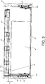
FIG. 3 is a rear view of the rack system according to an embodiment of the present invention; -
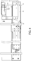
FIG. 4 is a lateral view of the rack system according to an embodiment of the present invention; -
FIG. 5 is a diagram showing the carried object being pulled out relative to a rack to move from the close position to a first position; -
FIG. 6 is an enlarged view of an area A ofFIG. 5 ; and -
FIG. 7 is a diagram showing the carried object being pulled out relative to the rack to move from the close position to a second position. -
FIG. 1 to FIG. 4 are diagrams showing a rack system according to an embodiment of the present invention. The rack system comprises arack 20, a firstslide rail assembly 24, a secondslide rail assembly 30, a carriedobject 36, and a firstcable management arm 38. Therack 20 has afirst side 22a and asecond side 22b. The firstslide rail assembly 24 is mounted to thefirst side 22a of therack 20. The firstslide rail assembly 24 at least comprises afirst rail 26 and asecond rail 28, wherein thesecond rail 28 is movable relative to thefirst rail 26. Preferably, the firstslide rail assembly 24 further comprises afirst middle rail 27 movably connected between thefirst rail 26 and thesecond rail 28 for extending a traveling distance of thesecond rail 28 relative to thefirst rail 26. The secondslide rail assembly 30 is mounted to thesecond side 22b of therack 20. Configuration of the secondslide rail assembly 30 can be identical to configuration of the firstslide rail assembly 24. The secondslide rail assembly 30 at least comprises athird rail 32 and afourth rail 34, wherein thefourth rail 34 is movable relative to thethird rail 32. Preferably, the secondslide rail assembly 30 further comprises asecond middle rail 33 movably connected between thethird rail 32 and thefourth rail 34 for extending a traveling distance of thefourth rail 34 relative to thethird rail 32. The carriedobject 36 can contain a hard disk, a power distribution unit and/or other electronic components. The carriedobject 36 is mounted between the firstslide rail assembly 24 and the secondslide rail assembly 30. The carriedobject 36 is movable relative to therack 20 between a close position (such as a front part P0 of the carriedobject 36 being adjacent to a front post of the rack 20) and an extension position (please refer toFIG. 5 andFIG. 7 ) through thesecond rail 28 of the firstslide rail assembly 24 and thefourth rail 34 of the secondslide rail assembly 30. The firstcable management arm 38 is detachably connected to one of therack 20, thefirst rail 26 of the firstslide rail assembly 24, and thethird rail 32 of the secondslide rail assembly 30. In the present embodiment, the firstcable management arm 38 is detachably connected to thefirst rail 26 of the firstslide rail assembly 24 through a supportingframe 40. But the present invention is not limited thereto. The firstcable management arm 38 can be connected to other fixed object. - Preferably, the rack system further comprises a second
cable management arm 42 pivotally connected to the firstcable management arm 38, such that the firstcable management arm 38 and the secondcable management arm 42 can be expanded (as shown inFIG. 5 andFIG. 7 ) or folded (as shown inFIG. 1 ). The secondcable management arm 42 is detachably connected to one of the carriedobject 36, thesecond rail 28 of the firstslide rail assembly 24, and thefourth rail 34 of the secondslide rail assembly 30. In the present embodiment, the secondcable management arm 42 is detachably connected to the carriedobject 36. But the present invention is not limited thereto. The secondcable management arm 42 can be connected to other aforementioned movable object, such as thesecond rail 28 of the firstslide rail assembly 24 or thefourth rail 34 of the secondslide rail assembly 30. - Preferably, the rack system further comprises a supporting
base 44 attached to the carriedobject 36 and configured to support one of the firstcable management arm 38 and the second cable management arm 42 (for example, when the carriedobject 36 is located at extension position as shown inFIG. 5 andFIG. 7 , the supportingbase 44 is configured to support the second cable management arm 42), or configured to support both the firstcable management arm 38 and the second cable management arm 42 (for example, when the carriedobject 36 is located at the close position as shown inFIG. 1 , the supportingbase 44 is configured to support both the firstcable management arm 38 and the second cable management arm 42). - Preferably, the supporting
base 44 is fixedly attached to the carriedobject 36. The supportingbase 44 has a first supportingleg 46a, a secondsupporting leg 46b and a supportingpart 48. The firstsupporting leg 46a is fixedly mounted to a lateral side of the carriedobject 36, and the second supportingleg 46b abuts against a plate member at an upper side of the carriedobject 36, such that a first supporting height h1 is defined between the supportingpart 48 and the upper side of the carried object 36 (please refer toFIG. 3 ). - Preferably, as shown in
FIG. 6 , the supportingbase 44 has a blockingpart 50 configured to prevent the secondcable management arm 42 from being deflected to an inappropriate position (such as being deflected to a position away from the supportingbase 44 without being supported by the supporting base 44). - Preferably, the rack system further comprises a linking
member 52 detachably connected between thefirst rail 26 of the firstslide rail assembly 24 and thethird rail 32 of the secondslide rail assembly 30 in order to enhance supporting capability of the slide rail assemblies. In the present embodiment, a connecting assembly of the present invention comprises the firstslide rail assembly 24, the secondslide rail assembly 30, the linkingmember 52, the firstcable management arm 38, the secondcable management arm 42 and the supportingbase 44. - Preferably, the supporting
frame 40 is fixedly mounted to one of thefirst rail 26 of the firstslide rail assembly 24 and thethird rail 32 of the secondslide rail assembly 30. In the present embodiment, the supportingframe 40 is fixedly mounted to thefirst rail 26 of the firstslide rail assembly 24. But the present invention is not limited thereto. In addition, as shown inFIG. 4 , the supportingframe 40 has a second supporting height h2 greater than a height h3 of thefirst rail 26 of the firstslide rail assembly 24. - Preferably, as shown in
FIG. 2 , the firstcable management arm 38 is arranged with a first connectingmember 54. The supportingframe 40 is arranged with a first correspondingmember 56. The first connectingmember 54 is detachably connected to the first correspondingmember 56. Preferably, the first connectingmember 54 is movably connected to the firstcable management arm 38. - Preferably, as shown in
FIG. 2 , the secondcable management arm 42 is arranged with a second connectingmember 58. On the other hand, a second correspondingmember 60 is fixedly mounted to the carriedobject 36. The second connectingmember 58 is detachably connected to the second correspondingmember 60. Preferably, the second connectingmember 58 is movably connected to the secondcable management arm 42. - As shown in
FIG. 5 to FIG. 7 , during a process of the carriedobject 36 being pulled out relative to therack 20 to move from the closed position (as shown inFIG. 1 ) to an extension position (such as a middle part P1 of the carriedobject 36 being adjacent to the front post of therack 20 shown inFIG. 5 , or a rear part P2 of the carriedobject 36 being adjacent to the front post of therack 20 shown inFIG. 7 ) along a first direction D1, the supportingbase 44 is configured to support one of the firstcable management arm 38 and the secondcable management arm 42, in order to prevent the firstcable management arm 38 and the secondcable management arm 42 from leaning downward, which affects movement of the carriedobject 36 relative to therack 20. On the other hand, since the linkingmember 52 is detachably connected between thefirst rail 26 of the firstslide rail assembly 24 and thethird rail 32 of the secondslide rail assembly 30, overall supporting structure of the slide rail assemblies can be enhanced, such that an overweight carried object can be reliably supported without causing deformation of the slide rail assemblies. - Therefore, the rack system of the present invention is characterized in that:
- 1. Cables of the carried object mounted in the rack can be supported more reliably.
- 2. The supporting structure for supporting the carried object on the rack can be enhanced.
Claims (15)
- A rack system, comprising:a rack (20) having a first side (22a) and a second side (22b) ;a first slide rail assembly (24) mounted to the first side (22a) of the rack (20), the first slide rail assembly (24) at least comprising a first rail (26) and a second rail (28), wherein the second rail (28) is movable relative to the first rail (26);a second slide rail assembly (30) mounted to the second side (22b) of the rack (20), the second slide rail assembly (30) at least comprising a third rail (32) and a fourth rail (34), wherein the fourth rail (34) is movable relative to the third rail (32);a carried object (36) mounted between the first slide rail assembly (24) and the second slide rail assembly (30), the carried object (36) being movable relative to the rack (20) between a close position and an extension position through the second rail (28) of the first slide rail assembly (24) and the fourth rail (34) of the second slide rail assembly (30);a first cable management arm (38) detachably connected to one of the rack (20), the first rail (26) of the first slide rail assembly (24) and the third rail (32) of the second slide rail assembly (30);a second cable management arm (42) pivotally connected to the first cable management arm (38), and detachably connected to one of the carried object (36), the second rail (28) of the first slide rail assembly (24) and the fourth rail (34) of the second slide rail assembly (30); andcharacterized by:a supporting base (44) attached to the carried object (36) and configured to support at least one of the first cable management arm (38) and the second cable management arm (42).
- The rack system of claim 1, further characterized by a linking member (52) detachably connected between the first rail (26) of the first slide rail assembly (24) and the third rail (32) of the second slide rail assembly (30).
- The rack system of claim 1 or 2, characterized in that the supporting base (44) is fixedly attached to the carried object (36), the supporting base (44) has a first supporting leg (46a), a second supporting leg (46b) and a supporting part (48), the first supporting leg (46a) is fixedly mounted to a lateral side of the carried object (36), and the second supporting leg (46b) abuts against an upper side of the carried object (36), a first supporting height is defined between the supporting part (48) and the upper side of the carried object (36).
- The rack system of claim 3, characterized in that the supporting base (44) has a blocking part (50) configured to prevent the second cable management arm (42) from being deflected away from the supporting base (44).
- The rack system of any of claims 1-4, further characterized by a supporting frame (40) fixedly mounted to one of the first rail (26) of the first slide rail assembly (24) and the third rail (32) of the second slide rail assembly (30), wherein the supporting frame (40) has a second supporting height greater than a height of each of the first rail (26) of the first slide rail assembly (24) and the third rail (32) of the second slide rail assembly (30).
- The rack system of claim 5, characterized in that the first cable management arm (38) is arranged with a first connecting member (54), the supporting frame (40) is arranged with a first corresponding member (56), and the first connecting member (54) is detachably connected to the first corresponding member (56).
- The rack system of claim 6, characterized in that the first connecting member (54) is movably connected to the first cable management arm (38).
- The rack system of any of claims 1-7, characterized in that the second cable management arm (42) is arranged with a second connecting member (58), the carried object (36) is arranged with a second corresponding member (60), and the second connecting member (58) is detachably connected to the second corresponding member (60).
- The rack system of claim 8, characterized in that the second connecting member (58) is movably connected to the second cable management arm (42).
- A rack system, comprising:a rack (20) having a first side (22a) and a second side (22b) ;a first slide rail assembly (24) mounted to the first side (22a) of the rack (20), the first slide rail assembly (24) at least comprising a first rail (26) and a second rail (28), wherein the second rail (28) is movable relative to the first rail (26);a second slide rail assembly (30) mounted to the second side (22b) of the rack (20), the second slide rail assembly (30) at least comprising a third rail (32) and a fourth rail (34), wherein the fourth rail (34) is movable relative to the third rail (32);a carried object (36) mounted between the first slide rail assembly (24) and the second slide rail assembly (30), the carried object (36) being movable relative to the rack (20) between a close position and an extension position through the second rail (28) of the first slide rail assembly (24) and the fourth rail (34) of the second slide rail assembly (30);a first cable management arm (38) detachably connected to one of the rack (20), the first rail (26) of the first slide rail assembly (24) and the third rail (32) of the second slide rail assembly (30);a second cable management arm (42) movably pivotally connected to the first cable management arm (38), and detachably connected to one of the carried object (36), the second rail (28) of the first slide rail assembly (24) and the fourth rail (34) of the second slide rail assembly (30); andcharacterized by:a linking member (52) detachably connected between the first rail (26) of the first slide rail assembly (24) and the third rail (32) of the second slide rail assembly (30).
- The rack system of claim 10, further characterized by a supporting frame (40) fixedly mounted to one of the first rail (26) of the first slide rail assembly (24) and the third rail (32) of the second slide rail assembly (30), wherein the supporting frame (40) has a second supporting height greater than a height of each of the first rail (26) of the first slide rail assembly (24) and the third rail (32) of the second slide rail assembly (30).
- The rack system of claim 11, characterized in that the first cable management arm (38) is arranged with a first connecting member (54), the supporting frame (40) is arranged with a first corresponding member (56), and the first connecting member (54) is detachably connected to the first corresponding member (56) and movably connected to the first cable management arm (38).
- The rack system of any of claims 10-12, characterized in that the second cable management arm (42) is arranged with a second connecting member (58), the carried object (36) is arranged with a second corresponding member (60), and the second connecting member (58) is detachably connected to the second corresponding member (60) and movably connected to the second cable management arm (42).
- A connecting assembly for a rack system, comprising:a first slide rail assembly (24) at least comprising a first rail (26) and a second rail (28), wherein the second rail (28) is movable relative to the first rail (26);a second slide rail assembly (30) at least comprising a third rail (32) and a fourth rail (34), wherein the fourth rail (34) is movable relative to the third rail (32);characterized by:a linking member (52) connected between the first rail (26) of the first slide rail assembly (24) and the third rail (32) of the second slide rail assembly (30);a first cable management arm (38) detachably connected to one of the first rail (26) of the first slide rail assembly (24) and the third rail (32) of the second slide rail assembly (30); anda second cable management arm (42) pivotally connected to the first cable management arm (38).
- The connecting assembly of claim 14, further characterized by a supporting base (44) attached to a carried object (36), wherein the carried object (36) is mounted between the first slide rail assembly (24) and the second slide rail assembly (30), and the supporting base (44) is configured to support at least one of the first cable management arm (38) and the second cable management arm (42).
Applications Claiming Priority (1)
| Application Number | Priority Date | Filing Date | Title |
|---|---|---|---|
| TW106121867A TWI617233B (en) | 2017-06-28 | 2017-06-28 | Rack system and connecting assembly for rack system |
Publications (2)
| Publication Number | Publication Date |
|---|---|
| EP3422830A1 true EP3422830A1 (en) | 2019-01-02 |
| EP3422830B1 EP3422830B1 (en) | 2021-02-24 |
Family
ID=61167952
Family Applications (1)
| Application Number | Title | Priority Date | Filing Date |
|---|---|---|---|
| EP18155257.1A Active EP3422830B1 (en) | 2017-06-28 | 2018-02-06 | Connecting assembly for rack system |
Country Status (4)
| Country | Link |
|---|---|
| US (1) | US10420247B2 (en) |
| EP (1) | EP3422830B1 (en) |
| JP (1) | JP6574277B2 (en) |
| TW (1) | TWI617233B (en) |
Cited By (1)
| Publication number | Priority date | Publication date | Assignee | Title |
|---|---|---|---|---|
| CN111263553A (en) * | 2018-12-03 | 2020-06-09 | 川湖科技股份有限公司 | Cable management assembly |
Families Citing this family (5)
| Publication number | Priority date | Publication date | Assignee | Title |
|---|---|---|---|---|
| GB2552549A (en) * | 2016-07-29 | 2018-01-31 | Univ Central Lancashire | Retaining device for a flexible line |
| US11423948B2 (en) * | 2018-09-03 | 2022-08-23 | Celestica Technology Consultancy (Shanghai) Co. Ltd | Storage chassis and electronic apparatus comprising the same |
| TWI681703B (en) * | 2019-02-25 | 2020-01-01 | 川湖科技股份有限公司 | Slide rail mechanism and supporting assembly thereof |
| US11013138B2 (en) * | 2019-05-09 | 2021-05-18 | International Business Machines Corporation | Cable management assembly for managing cables of rack-mounted computers |
| US11538132B2 (en) * | 2019-12-27 | 2022-12-27 | Quanta Computer Inc. | Application and integration of a GPU server system |
Citations (4)
| Publication number | Priority date | Publication date | Assignee | Title |
|---|---|---|---|---|
| US6600665B2 (en) | 2001-08-03 | 2003-07-29 | Hewlett-Packard Development Company, L.P. | Cable management arm with trough and breakaway feature |
| US8186634B2 (en) | 2007-09-06 | 2012-05-29 | King Slide Works Co., Ltd. | Cable management arm supporting device |
| US9144174B2 (en) | 2012-12-07 | 2015-09-22 | King Slide Works Co., Ltd. | Cable management arm assembly |
| US9383038B2 (en) * | 2014-12-04 | 2016-07-05 | King Slide Works Co., Ltd. | Cable management arm supporting device and mounting assembly thereof |
Family Cites Families (16)
| Publication number | Priority date | Publication date | Assignee | Title |
|---|---|---|---|---|
| US3138655A (en) * | 1962-04-24 | 1964-06-23 | Robert W Navarro | Electrical cable retractor with quick disconnect hinge |
| US4353518A (en) * | 1980-12-22 | 1982-10-12 | General Electric Company | Cable retractor |
| US6021047A (en) * | 1997-10-24 | 2000-02-01 | Dell U.S.A., L,P. | Computer and a rack mount system and method for a computer |
| US6326547B1 (en) * | 1999-11-02 | 2001-12-04 | Compaq Computer Corporation | Cable management system |
| US6392149B1 (en) * | 2001-09-13 | 2002-05-21 | Sun Microsystems, Inc. | Apparatus and method for routing cables |
| US6854605B2 (en) * | 2002-06-10 | 2005-02-15 | Sun Microsystems, Inc. | Cable management system |
| US6972949B1 (en) * | 2003-12-03 | 2005-12-06 | Unisys Corporation | Cable routing system |
| US20060081736A1 (en) * | 2004-10-15 | 2006-04-20 | Ken-Ching Chen | Support slide for cable management arm |
| US7189924B1 (en) * | 2005-07-01 | 2007-03-13 | Sun Microsystems, Inc. | Rack-mount computer cable management arm |
| US7473846B2 (en) * | 2006-03-29 | 2009-01-06 | Hewlett-Packard Development Company, L.P. | Reversible cable support arm |
| US7594628B2 (en) * | 2006-11-10 | 2009-09-29 | Hon Hai Precision Industry Co., Ltd. | Mounting apparatus for cable management arm |
| CN101562958B (en) * | 2008-04-16 | 2012-11-21 | 鸿富锦精密工业(深圳)有限公司 | Wire-management device |
| US8729389B2 (en) * | 2008-09-25 | 2014-05-20 | Xyratex Technology Limited | Apparatus comprising rack, component, cable and cable management assembly |
| US8379410B2 (en) * | 2009-10-30 | 2013-02-19 | Dell Products L.P. | Reversible cable management arm |
| TWI478456B (en) * | 2013-02-22 | 2015-03-21 | King Slide Works Co Ltd | Cable management arm |
| TWI556711B (en) * | 2015-05-05 | 2016-11-01 | King Slide Works Co Ltd | Cable management device |
-
2017
- 2017-06-28 TW TW106121867A patent/TWI617233B/en active
- 2017-12-26 US US15/854,065 patent/US10420247B2/en active Active
-
2018
- 2018-02-01 JP JP2018016056A patent/JP6574277B2/en active Active
- 2018-02-06 EP EP18155257.1A patent/EP3422830B1/en active Active
Patent Citations (4)
| Publication number | Priority date | Publication date | Assignee | Title |
|---|---|---|---|---|
| US6600665B2 (en) | 2001-08-03 | 2003-07-29 | Hewlett-Packard Development Company, L.P. | Cable management arm with trough and breakaway feature |
| US8186634B2 (en) | 2007-09-06 | 2012-05-29 | King Slide Works Co., Ltd. | Cable management arm supporting device |
| US9144174B2 (en) | 2012-12-07 | 2015-09-22 | King Slide Works Co., Ltd. | Cable management arm assembly |
| US9383038B2 (en) * | 2014-12-04 | 2016-07-05 | King Slide Works Co., Ltd. | Cable management arm supporting device and mounting assembly thereof |
Cited By (2)
| Publication number | Priority date | Publication date | Assignee | Title |
|---|---|---|---|---|
| CN111263553A (en) * | 2018-12-03 | 2020-06-09 | 川湖科技股份有限公司 | Cable management assembly |
| CN111263553B (en) * | 2018-12-03 | 2021-04-09 | 川湖科技股份有限公司 | Cable management assembly |
Also Published As
| Publication number | Publication date |
|---|---|
| US20190008069A1 (en) | 2019-01-03 |
| JP2019009410A (en) | 2019-01-17 |
| JP6574277B2 (en) | 2019-09-11 |
| EP3422830B1 (en) | 2021-02-24 |
| TW201906517A (en) | 2019-02-01 |
| TWI617233B (en) | 2018-03-01 |
| US10420247B2 (en) | 2019-09-17 |
Similar Documents
| Publication | Publication Date | Title |
|---|---|---|
| EP3422830B1 (en) | Connecting assembly for rack system | |
| US10356932B2 (en) | Cable management device and connecting assembly for rack system | |
| EP3154320B1 (en) | Slide rail assembly and bracket device thereof | |
| EP3094165A1 (en) | Slide rail assembly | |
| EP3398481B1 (en) | Slide rail assembly | |
| EP3258755B1 (en) | Rack system | |
| EP3273757B1 (en) | Slide rail assembly for rack system | |
| EP3143901A1 (en) | Slide rail assembly | |
| EP3457826B1 (en) | Rack system and slide rail assembly thereof | |
| EP3657919B1 (en) | Cable management assembly | |
| EP3637968B1 (en) | Cable management assembly | |
| EP3282529A1 (en) | Cable management assembly and cable management device thereof | |
| EP3251556A1 (en) | Slide rail and slide rail assembly | |
| JP2017076771A (en) | Slide rail assembly for rack system | |
| EP2753160A2 (en) | Adjustable 4-post rack | |
| JP6568140B2 (en) | Cable management device and slide rail assembly using the same | |
| EP3419395A1 (en) | Bracket assembly for a rack | |
| EP3258754B1 (en) | Rack system and slide rail assemblies thereof | |
| US20140265793A1 (en) | Bidirectional slide rail | |
| JP2018161461A (en) | Bracket and slide rail assembly using the same | |
| CN107801348B (en) | Slide rail assembly and its cable management device | |
| EP3310033B1 (en) | Slide rail assembly | |
| EP2777431B1 (en) | Support structure for support bracket and rail | |
| EP3005901A1 (en) | Slide rail assembly | |
| EP3772243A1 (en) | Slide rail mechanism |
Legal Events
| Date | Code | Title | Description |
|---|---|---|---|
| PUAI | Public reference made under article 153(3) epc to a published international application that has entered the european phase |
Free format text: ORIGINAL CODE: 0009012 |
|
| STAA | Information on the status of an ep patent application or granted ep patent |
Free format text: STATUS: THE APPLICATION HAS BEEN PUBLISHED |
|
| AK | Designated contracting states |
Kind code of ref document: A1 Designated state(s): AL AT BE BG CH CY CZ DE DK EE ES FI FR GB GR HR HU IE IS IT LI LT LU LV MC MK MT NL NO PL PT RO RS SE SI SK SM TR |
|
| AX | Request for extension of the european patent |
Extension state: BA ME |
|
| STAA | Information on the status of an ep patent application or granted ep patent |
Free format text: STATUS: REQUEST FOR EXAMINATION WAS MADE |
|
| 17P | Request for examination filed |
Effective date: 20190103 |
|
| RBV | Designated contracting states (corrected) |
Designated state(s): AL AT BE BG CH CY CZ DE DK EE ES FI FR GB GR HR HU IE IS IT LI LT LU LV MC MK MT NL NO PL PT RO RS SE SI SK SM TR |
|
| GRAP | Despatch of communication of intention to grant a patent |
Free format text: ORIGINAL CODE: EPIDOSNIGR1 |
|
| STAA | Information on the status of an ep patent application or granted ep patent |
Free format text: STATUS: GRANT OF PATENT IS INTENDED |
|
| INTG | Intention to grant announced |
Effective date: 20201103 |
|
| GRAS | Grant fee paid |
Free format text: ORIGINAL CODE: EPIDOSNIGR3 |
|
| GRAA | (expected) grant |
Free format text: ORIGINAL CODE: 0009210 |
|
| STAA | Information on the status of an ep patent application or granted ep patent |
Free format text: STATUS: THE PATENT HAS BEEN GRANTED |
|
| AK | Designated contracting states |
Kind code of ref document: B1 Designated state(s): AL AT BE BG CH CY CZ DE DK EE ES FI FR GB GR HR HU IE IS IT LI LT LU LV MC MK MT NL NO PL PT RO RS SE SI SK SM TR |
|
| REG | Reference to a national code |
Ref country code: CH Ref legal event code: EP |
|
| REG | Reference to a national code |
Ref country code: AT Ref legal event code: REF Ref document number: 1366135 Country of ref document: AT Kind code of ref document: T Effective date: 20210315 |
|
| REG | Reference to a national code |
Ref country code: IE Ref legal event code: FG4D |
|
| REG | Reference to a national code |
Ref country code: DE Ref legal event code: R096 Ref document number: 602018012839 Country of ref document: DE |
|
| REG | Reference to a national code |
Ref country code: LT Ref legal event code: MG9D |
|
| REG | Reference to a national code |
Ref country code: NL Ref legal event code: MP Effective date: 20210224 |
|
| PG25 | Lapsed in a contracting state [announced via postgrant information from national office to epo] |
Ref country code: FI Free format text: LAPSE BECAUSE OF FAILURE TO SUBMIT A TRANSLATION OF THE DESCRIPTION OR TO PAY THE FEE WITHIN THE PRESCRIBED TIME-LIMIT Effective date: 20210224 Ref country code: GR Free format text: LAPSE BECAUSE OF FAILURE TO SUBMIT A TRANSLATION OF THE DESCRIPTION OR TO PAY THE FEE WITHIN THE PRESCRIBED TIME-LIMIT Effective date: 20210525 Ref country code: HR Free format text: LAPSE BECAUSE OF FAILURE TO SUBMIT A TRANSLATION OF THE DESCRIPTION OR TO PAY THE FEE WITHIN THE PRESCRIBED TIME-LIMIT Effective date: 20210224 Ref country code: PT Free format text: LAPSE BECAUSE OF FAILURE TO SUBMIT A TRANSLATION OF THE DESCRIPTION OR TO PAY THE FEE WITHIN THE PRESCRIBED TIME-LIMIT Effective date: 20210624 Ref country code: NO Free format text: LAPSE BECAUSE OF FAILURE TO SUBMIT A TRANSLATION OF THE DESCRIPTION OR TO PAY THE FEE WITHIN THE PRESCRIBED TIME-LIMIT Effective date: 20210524 Ref country code: LT Free format text: LAPSE BECAUSE OF FAILURE TO SUBMIT A TRANSLATION OF THE DESCRIPTION OR TO PAY THE FEE WITHIN THE PRESCRIBED TIME-LIMIT Effective date: 20210224 Ref country code: BG Free format text: LAPSE BECAUSE OF FAILURE TO SUBMIT A TRANSLATION OF THE DESCRIPTION OR TO PAY THE FEE WITHIN THE PRESCRIBED TIME-LIMIT Effective date: 20210524 |
|
| REG | Reference to a national code |
Ref country code: AT Ref legal event code: MK05 Ref document number: 1366135 Country of ref document: AT Kind code of ref document: T Effective date: 20210224 |
|
| PG25 | Lapsed in a contracting state [announced via postgrant information from national office to epo] |
Ref country code: NL Free format text: LAPSE BECAUSE OF FAILURE TO SUBMIT A TRANSLATION OF THE DESCRIPTION OR TO PAY THE FEE WITHIN THE PRESCRIBED TIME-LIMIT Effective date: 20210224 Ref country code: RS Free format text: LAPSE BECAUSE OF FAILURE TO SUBMIT A TRANSLATION OF THE DESCRIPTION OR TO PAY THE FEE WITHIN THE PRESCRIBED TIME-LIMIT Effective date: 20210224 Ref country code: LV Free format text: LAPSE BECAUSE OF FAILURE TO SUBMIT A TRANSLATION OF THE DESCRIPTION OR TO PAY THE FEE WITHIN THE PRESCRIBED TIME-LIMIT Effective date: 20210224 Ref country code: PL Free format text: LAPSE BECAUSE OF FAILURE TO SUBMIT A TRANSLATION OF THE DESCRIPTION OR TO PAY THE FEE WITHIN THE PRESCRIBED TIME-LIMIT Effective date: 20210224 Ref country code: SE Free format text: LAPSE BECAUSE OF FAILURE TO SUBMIT A TRANSLATION OF THE DESCRIPTION OR TO PAY THE FEE WITHIN THE PRESCRIBED TIME-LIMIT Effective date: 20210224 |
|
| PG25 | Lapsed in a contracting state [announced via postgrant information from national office to epo] |
Ref country code: IS Free format text: LAPSE BECAUSE OF FAILURE TO SUBMIT A TRANSLATION OF THE DESCRIPTION OR TO PAY THE FEE WITHIN THE PRESCRIBED TIME-LIMIT Effective date: 20210624 |
|
| PG25 | Lapsed in a contracting state [announced via postgrant information from national office to epo] |
Ref country code: CZ Free format text: LAPSE BECAUSE OF FAILURE TO SUBMIT A TRANSLATION OF THE DESCRIPTION OR TO PAY THE FEE WITHIN THE PRESCRIBED TIME-LIMIT Effective date: 20210224 Ref country code: EE Free format text: LAPSE BECAUSE OF FAILURE TO SUBMIT A TRANSLATION OF THE DESCRIPTION OR TO PAY THE FEE WITHIN THE PRESCRIBED TIME-LIMIT Effective date: 20210224 Ref country code: SM Free format text: LAPSE BECAUSE OF FAILURE TO SUBMIT A TRANSLATION OF THE DESCRIPTION OR TO PAY THE FEE WITHIN THE PRESCRIBED TIME-LIMIT Effective date: 20210224 Ref country code: AT Free format text: LAPSE BECAUSE OF FAILURE TO SUBMIT A TRANSLATION OF THE DESCRIPTION OR TO PAY THE FEE WITHIN THE PRESCRIBED TIME-LIMIT Effective date: 20210224 |
|
| REG | Reference to a national code |
Ref country code: DE Ref legal event code: R097 Ref document number: 602018012839 Country of ref document: DE |
|
| PG25 | Lapsed in a contracting state [announced via postgrant information from national office to epo] |
Ref country code: RO Free format text: LAPSE BECAUSE OF FAILURE TO SUBMIT A TRANSLATION OF THE DESCRIPTION OR TO PAY THE FEE WITHIN THE PRESCRIBED TIME-LIMIT Effective date: 20210224 Ref country code: DK Free format text: LAPSE BECAUSE OF FAILURE TO SUBMIT A TRANSLATION OF THE DESCRIPTION OR TO PAY THE FEE WITHIN THE PRESCRIBED TIME-LIMIT Effective date: 20210224 Ref country code: SK Free format text: LAPSE BECAUSE OF FAILURE TO SUBMIT A TRANSLATION OF THE DESCRIPTION OR TO PAY THE FEE WITHIN THE PRESCRIBED TIME-LIMIT Effective date: 20210224 |
|
| PLBE | No opposition filed within time limit |
Free format text: ORIGINAL CODE: 0009261 |
|
| STAA | Information on the status of an ep patent application or granted ep patent |
Free format text: STATUS: NO OPPOSITION FILED WITHIN TIME LIMIT |
|
| PG25 | Lapsed in a contracting state [announced via postgrant information from national office to epo] |
Ref country code: AL Free format text: LAPSE BECAUSE OF FAILURE TO SUBMIT A TRANSLATION OF THE DESCRIPTION OR TO PAY THE FEE WITHIN THE PRESCRIBED TIME-LIMIT Effective date: 20210224 Ref country code: ES Free format text: LAPSE BECAUSE OF FAILURE TO SUBMIT A TRANSLATION OF THE DESCRIPTION OR TO PAY THE FEE WITHIN THE PRESCRIBED TIME-LIMIT Effective date: 20210224 |
|
| 26N | No opposition filed |
Effective date: 20211125 |
|
| PG25 | Lapsed in a contracting state [announced via postgrant information from national office to epo] |
Ref country code: SI Free format text: LAPSE BECAUSE OF FAILURE TO SUBMIT A TRANSLATION OF THE DESCRIPTION OR TO PAY THE FEE WITHIN THE PRESCRIBED TIME-LIMIT Effective date: 20210224 |
|
| PG25 | Lapsed in a contracting state [announced via postgrant information from national office to epo] |
Ref country code: IT Free format text: LAPSE BECAUSE OF FAILURE TO SUBMIT A TRANSLATION OF THE DESCRIPTION OR TO PAY THE FEE WITHIN THE PRESCRIBED TIME-LIMIT Effective date: 20210224 |
|
| PG25 | Lapsed in a contracting state [announced via postgrant information from national office to epo] |
Ref country code: IS Free format text: LAPSE BECAUSE OF FAILURE TO SUBMIT A TRANSLATION OF THE DESCRIPTION OR TO PAY THE FEE WITHIN THE PRESCRIBED TIME-LIMIT Effective date: 20210624 |
|
| PG25 | Lapsed in a contracting state [announced via postgrant information from national office to epo] |
Ref country code: MC Free format text: LAPSE BECAUSE OF FAILURE TO SUBMIT A TRANSLATION OF THE DESCRIPTION OR TO PAY THE FEE WITHIN THE PRESCRIBED TIME-LIMIT Effective date: 20210224 |
|
| REG | Reference to a national code |
Ref country code: CH Ref legal event code: PL |
|
| REG | Reference to a national code |
Ref country code: BE Ref legal event code: MM Effective date: 20220228 |
|
| PG25 | Lapsed in a contracting state [announced via postgrant information from national office to epo] |
Ref country code: LU Free format text: LAPSE BECAUSE OF NON-PAYMENT OF DUE FEES Effective date: 20220206 |
|
| PG25 | Lapsed in a contracting state [announced via postgrant information from national office to epo] |
Ref country code: FR Free format text: LAPSE BECAUSE OF NON-PAYMENT OF DUE FEES Effective date: 20220228 |
|
| PG25 | Lapsed in a contracting state [announced via postgrant information from national office to epo] |
Ref country code: LI Free format text: LAPSE BECAUSE OF NON-PAYMENT OF DUE FEES Effective date: 20220228 Ref country code: CH Free format text: LAPSE BECAUSE OF NON-PAYMENT OF DUE FEES Effective date: 20220228 |
|
| PG25 | Lapsed in a contracting state [announced via postgrant information from national office to epo] |
Ref country code: BE Free format text: LAPSE BECAUSE OF NON-PAYMENT OF DUE FEES Effective date: 20220228 |
|
| PG25 | Lapsed in a contracting state [announced via postgrant information from national office to epo] |
Ref country code: HU Free format text: LAPSE BECAUSE OF FAILURE TO SUBMIT A TRANSLATION OF THE DESCRIPTION OR TO PAY THE FEE WITHIN THE PRESCRIBED TIME-LIMIT; INVALID AB INITIO Effective date: 20180206 |
|
| PG25 | Lapsed in a contracting state [announced via postgrant information from national office to epo] |
Ref country code: MK Free format text: LAPSE BECAUSE OF FAILURE TO SUBMIT A TRANSLATION OF THE DESCRIPTION OR TO PAY THE FEE WITHIN THE PRESCRIBED TIME-LIMIT Effective date: 20210224 Ref country code: CY Free format text: LAPSE BECAUSE OF FAILURE TO SUBMIT A TRANSLATION OF THE DESCRIPTION OR TO PAY THE FEE WITHIN THE PRESCRIBED TIME-LIMIT Effective date: 20210224 |
|
| PG25 | Lapsed in a contracting state [announced via postgrant information from national office to epo] |
Ref country code: TR Free format text: LAPSE BECAUSE OF FAILURE TO SUBMIT A TRANSLATION OF THE DESCRIPTION OR TO PAY THE FEE WITHIN THE PRESCRIBED TIME-LIMIT Effective date: 20210224 |
|
| PG25 | Lapsed in a contracting state [announced via postgrant information from national office to epo] |
Ref country code: MT Free format text: LAPSE BECAUSE OF FAILURE TO SUBMIT A TRANSLATION OF THE DESCRIPTION OR TO PAY THE FEE WITHIN THE PRESCRIBED TIME-LIMIT Effective date: 20210224 |
|
| PGFP | Annual fee paid to national office [announced via postgrant information from national office to epo] |
Ref country code: GB Payment date: 20251208 Year of fee payment: 9 |
|
| PGFP | Annual fee paid to national office [announced via postgrant information from national office to epo] |
Ref country code: IE Payment date: 20251208 Year of fee payment: 9 |
|
| PGFP | Annual fee paid to national office [announced via postgrant information from national office to epo] |
Ref country code: DE Payment date: 20251211 Year of fee payment: 9 |