EP3422801A1 - Communication apparatus, method of controlling communication apparatus, and program - Google Patents
Communication apparatus, method of controlling communication apparatus, and program Download PDFInfo
- Publication number
- EP3422801A1 EP3422801A1 EP18176450.7A EP18176450A EP3422801A1 EP 3422801 A1 EP3422801 A1 EP 3422801A1 EP 18176450 A EP18176450 A EP 18176450A EP 3422801 A1 EP3422801 A1 EP 3422801A1
- Authority
- EP
- European Patent Office
- Prior art keywords
- service
- information
- identifying
- functioning
- piconet
- Prior art date
- Legal status (The legal status is an assumption and is not a legal conclusion. Google has not performed a legal analysis and makes no representation as to the accuracy of the status listed.)
- Withdrawn
Links
Images


Classifications
-
- H—ELECTRICITY
- H04—ELECTRIC COMMUNICATION TECHNIQUE
- H04W—WIRELESS COMMUNICATION NETWORKS
- H04W76/00—Connection management
- H04W76/10—Connection setup
- H04W76/14—Direct-mode setup
-
- H—ELECTRICITY
- H04—ELECTRIC COMMUNICATION TECHNIQUE
- H04W—WIRELESS COMMUNICATION NETWORKS
- H04W4/00—Services specially adapted for wireless communication networks; Facilities therefor
- H04W4/80—Services using short range communication, e.g. near-field communication [NFC], radio-frequency identification [RFID] or low energy communication
-
- H—ELECTRICITY
- H04—ELECTRIC COMMUNICATION TECHNIQUE
- H04W—WIRELESS COMMUNICATION NETWORKS
- H04W84/00—Network topologies
- H04W84/18—Self-organising networks, e.g. ad-hoc networks or sensor networks
-
- H—ELECTRICITY
- H04—ELECTRIC COMMUNICATION TECHNIQUE
- H04B—TRANSMISSION
- H04B1/00—Details of transmission systems, not covered by a single one of groups H04B3/00 - H04B13/00; Details of transmission systems not characterised by the medium used for transmission
- H04B1/38—Transceivers, i.e. devices in which transmitter and receiver form a structural unit and in which at least one part is used for functions of transmitting and receiving
- H04B1/3827—Portable transceivers
- H04B1/385—Transceivers carried on the body, e.g. in helmets
-
- H—ELECTRICITY
- H04—ELECTRIC COMMUNICATION TECHNIQUE
- H04L—TRANSMISSION OF DIGITAL INFORMATION, e.g. TELEGRAPHIC COMMUNICATION
- H04L67/00—Network arrangements or protocols for supporting network services or applications
- H04L67/01—Protocols
- H04L67/04—Protocols specially adapted for terminals or networks with limited capabilities; specially adapted for terminal portability
-
- H—ELECTRICITY
- H04—ELECTRIC COMMUNICATION TECHNIQUE
- H04L—TRANSMISSION OF DIGITAL INFORMATION, e.g. TELEGRAPHIC COMMUNICATION
- H04L67/00—Network arrangements or protocols for supporting network services or applications
- H04L67/14—Session management
-
- H—ELECTRICITY
- H04—ELECTRIC COMMUNICATION TECHNIQUE
- H04L—TRANSMISSION OF DIGITAL INFORMATION, e.g. TELEGRAPHIC COMMUNICATION
- H04L67/00—Network arrangements or protocols for supporting network services or applications
- H04L67/50—Network services
- H04L67/51—Discovery or management thereof, e.g. service location protocol [SLP] or web services
-
- H—ELECTRICITY
- H04—ELECTRIC COMMUNICATION TECHNIQUE
- H04L—TRANSMISSION OF DIGITAL INFORMATION, e.g. TELEGRAPHIC COMMUNICATION
- H04L67/00—Network arrangements or protocols for supporting network services or applications
- H04L67/50—Network services
- H04L67/56—Provisioning of proxy services
-
- H—ELECTRICITY
- H04—ELECTRIC COMMUNICATION TECHNIQUE
- H04W—WIRELESS COMMUNICATION NETWORKS
- H04W4/00—Services specially adapted for wireless communication networks; Facilities therefor
- H04W4/20—Services signaling; Auxiliary data signalling, i.e. transmitting data via a non-traffic channel
- H04W4/23—Services signaling; Auxiliary data signalling, i.e. transmitting data via a non-traffic channel for mobile advertising
-
- H—ELECTRICITY
- H04—ELECTRIC COMMUNICATION TECHNIQUE
- H04W—WIRELESS COMMUNICATION NETWORKS
- H04W48/00—Access restriction; Network selection; Access point selection
- H04W48/16—Discovering, processing access restriction or access information
-
- H—ELECTRICITY
- H04—ELECTRIC COMMUNICATION TECHNIQUE
- H04W—WIRELESS COMMUNICATION NETWORKS
- H04W8/00—Network data management
- H04W8/005—Discovery of network devices, e.g. terminals
-
- H—ELECTRICITY
- H04—ELECTRIC COMMUNICATION TECHNIQUE
- H04W—WIRELESS COMMUNICATION NETWORKS
- H04W84/00—Network topologies
- H04W84/18—Self-organising networks, e.g. ad-hoc networks or sensor networks
- H04W84/20—Leader-follower arrangements
-
- H—ELECTRICITY
- H04—ELECTRIC COMMUNICATION TECHNIQUE
- H04W—WIRELESS COMMUNICATION NETWORKS
- H04W92/00—Interfaces specially adapted for wireless communication networks
- H04W92/02—Inter-networking arrangements
-
- H—ELECTRICITY
- H04—ELECTRIC COMMUNICATION TECHNIQUE
- H04W—WIRELESS COMMUNICATION NETWORKS
- H04W88/00—Devices specially adapted for wireless communication networks, e.g. terminals, base stations or access point devices
- H04W88/16—Gateway arrangements
-
- H—ELECTRICITY
- H04—ELECTRIC COMMUNICATION TECHNIQUE
- H04W—WIRELESS COMMUNICATION NETWORKS
- H04W88/00—Devices specially adapted for wireless communication networks, e.g. terminals, base stations or access point devices
- H04W88/18—Service support devices; Network management devices
- H04W88/182—Network node acting on behalf of an other network entity, e.g. proxy
Definitions
- the present invention relates to a communication apparatus, a method of controlling the communication apparatus, and a program.
- a radio sensor network system In recent years, a radio sensor network system has been put to practical use, in which a communication apparatus collects a result measured by a sensing device existing in the neighborhood via communication by a short-range radio communication method and uses it as additional information of a service to be provided.
- a communication apparatus collects a result measured by a sensing device existing in the neighborhood via communication by a short-range radio communication method and uses it as additional information of a service to be provided.
- Bluetooth® As one of short-range radio communication methods, when devices enjoy a radio sensor network service, a pairing operation needs to be executed for each combination of devices that enjoy the service.
- the system using Bluetooth can use a "scatter network function" that allows a communication apparatus to hold a piconet (network) already formed with a sensing device and also newly participate in a piconet formed by an information processing apparatus in the neighborhood.
- a piconet network
- an information processing apparatus in the neighborhood.
- the mobile communication apparatus can execute reproduction of music data stored in the mobile communication apparatus in the in-vehicle information processing apparatus by using the scatter network function.
- the in-vehicle information processing apparatus is required to automatically collect vital information measured by the sensing device held by the user.
- the standards of Bluetooth associated with the scatter network include a standard for the topology of communication connection, there is no standard for bridge/routing and the like of data.
- the in-vehicle information processing apparatus cannot acquire measurement information of the sensing device only by forming the scatter network by the mobile communication apparatus.
- Japanese Patent Laid-Open No. 2013-59075 discloses a system in which a specific information communication apparatus makes a proxy response concerning control information in the system and executes control of setting of a payload data communication radio link between an information providing apparatus and an information receiving apparatus.
- Japanese Patent Laid-Open No. 2006-515492 discloses a system in which a communication apparatus at the estimated existence position of a radio communication apparatus makes a proxy response to an in-zone confirmation message of a radio system.
- Japanese Patent Laid-Open No. 2013-537754 discloses a method of providing a relay server between an information providing apparatus and an information receiving apparatus and updating information in accordance with the frequency of access to the relay server.
- the in-vehicle information communication apparatus cannot acquire sensing information via the mobile communication apparatus only by forming the scatter network with the mobile communication apparatus that is operating as a master communication apparatus of a piconet for controlling a sensing device group.
- a pairing operation between the in-vehicle information communication apparatus and each sensing device is necessary, and this operation is a burden on the user.
- the present invention provides a technique of efficiently performing communication to use a service in consideration of the above-described problem.
- the present invention in its first aspect provides a communication apparatus as specified in Claims 1 to 11.
- the present invention in its second aspect provides a method of controlling a communication apparatus as specified in Claim 12.
- the present invention in its third aspect provides a program as specified in Claim 13.
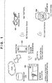
- Fig. 1 is a schematic view of a system (to be referred to as a sensing information collection system hereinafter) according to this embodiment, in which a result measured by a sensing device is collected via communication by a short-range radio communication method.
- This system is formed by a wearable camera 101 and a pulse rate meter 104 which serve as sensing devices, and a smartphone 102 and an in-vehicle information communication apparatus (IVI (In-Vehicle Infotainment)) 103 which serve as mobile communication apparatuses.
- the wearable camera 101 and the pulse rate meter 104 are worn or held by, for example, the driver of a vehicle in which the in-vehicle information communication apparatus 103 is mounted.
- Each of the wearable camera 101, the smartphone 102, the in-vehicle information communication apparatus 103, and the pulse rate meter 104 includes a radio communication interface based on the Bluetooth standard that is an example of short-range radio communication standards. Note that the devices are examples and are not limited to the devices shown in Fig. 1 as long as each device is a device including a radio communication interface based on the Bluetooth standard.
- the smartphone 102 serving as a central device of BLE (Bluetooth Low Energy) connection forms a piconet with a sensing device (the wearable camera 101 and/or the pulse rate meter 104).
- the BLE connection is done via a Bluetooth communication path.
- the piconet will be referred to as a lower piconet.
- the wearable camera 101 and the pulse rate meter 104 function as peripheral devices of BLE connection.
- the smartphone 102 participates as a peripheral device in a piconet formed by the in-vehicle information communication apparatus 103 that is a central device of new BLE connection, thereby forming a scatter network.
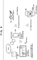
- Fig. 6 is a schematic view of a conventional sensing information collection system.
- the smartphone 102 can collect a measurement data value from a sensing device in the lower piconet.
- a pairing operation between the sensing device and the in-vehicle information communication apparatus 103 needs to be performed by the user.
- the smartphone 102 can transmit the measurement data value collected from the sensing device to the in-vehicle information communication apparatus 103 by proxy for the sensing device by performing processing to be described later.
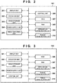
- Fig. 2 is a block diagram for explaining the hardware arrangement of the wearable camera 101.
- the wearable camera 101 includes a display unit 201, an operation unit 202, an image storage unit 203, a power supply unit 204, an image capturing unit 205, a control unit 206, a ROM 207, a RAM 208, a wireless LAN communication unit 209, and a Bluetooth communication unit 210.
- ROM Read Only Memory
- RAM stands for Random Access Memory.
- the display unit 201 is formed by, for example, an LCD (Liquid Crystal Display) or the like, has a function of outputting information that can visually be recognized, and performs display such as display of a UI (User Interface), an alarm, and an image.
- the operation unit 202 has a function of performing various kinds of inputs and the like and operating the device.
- the image storage unit 203 is formed by, for example, a nonvolatile memory medium such as an SD card and stores image data.
- the power supply unit 204 holds a power supply (a battery or the like) used to operate the entire device and supplies power to each hardware.
- the image capturing unit 205 is formed by, for example, an image capturing engine mainly including a lens and an image sensor, and generates image data by encoding a captured image.
- the control unit 206 is formed by, for example, one or a plurality of CPUs (Central Processing Units), and controls the operation of the entire wearable camera 101.
- the ROM 207 stores control instructions, that is, programs. Various kinds of operations of the wearable camera 101 to be described later are implemented when the control unit 206 executes a control program stored in the ROM 207.
- the RAM 208 is used as a work memory when executing a program or to temporarily save data.
- the wireless LAN communication unit 209 performs communication (Wi-Fi® or the like) complying with the IEEE802.11 series, and is used for high-speed transfer of payload data such as image data.
- the Bluetooth communication unit 210 performs Bluetooth communication that is power-saving radio communication.
- Fig. 3 is a block diagram for explaining the hardware arrangement of the smartphone 102.
- the smartphone 102 includes a display unit 301, an operation unit 302, an image storage unit 303, a power supply unit 304, a control unit 305, a ROM 306, a RAM 307, a wireless LAN communication unit 308, a Bluetooth communication unit 309, and a public communication unit 310.
- the display unit 301 is formed by, for example, an LCD or an LED (Light Emitting Diode), has a function of outputting information that can visually be recognized, and performs display of a UI, an alarm, and the like.
- the operation unit 302 has a function of performing various kinds of inputs and the like and operating the device.
- the image storage unit 303 stores image data.
- the power supply unit 304 holds a power supply (a battery or the like) used to operate the entire device and supplies power to each hardware.
- the control unit 305 is formed by one or a plurality of CPUs, and controls the operation of the entire smartphone 102.
- the ROM 306 stores control instructions, that is, programs. Various kinds of operations of the smartphone 102 to be described later are implemented when the control unit 305 executes a control program stored in the ROM 306.
- the RAM 307 is used as a work memory when executing a program or to temporarily save data.
- the wireless LAN communication unit 308 performs communication (Wi-Fi or the like) complying with the IEEE802.11 series.
- the Bluetooth communication unit 309 performs Bluetooth communication that is power-saving radio communication.
- the Bluetooth communication unit 309 communicates with the sensing devices (the wearable camera 101 and the pulse rate meter 104) in the neighborhood and the in-vehicle information communication apparatus 103.
- the public communication unit 310 performs public radio communication such as 3GPP (3rd Generation Partnership Project) and LTE (Long Term Evolution).
- the in-vehicle information communication apparatus (IVI) 103 will be described next.
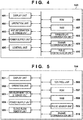
- Fig. 4 is a block diagram for explaining the hardware arrangement of the in-vehicle information communication apparatus.
- the in-vehicle information communication apparatus (IVI) 103 includes a display unit 401, an operation unit 402, a map information storage unit 403, a power supply unit 404, a control unit 405, a ROM 406, a RAM 407, a wireless LAN communication unit 408, a Bluetooth communication unit 409, and a public communication unit 410.
- the display unit 401 is formed by, for example, an LCD or an LED, has a function of outputting information that can visually be recognized, and performs display of a UI, an alarm, and the like.
- the operation unit 402 has a function of performing various kinds of inputs and the like and operating the device.
- the map information storage unit 403 is formed by, for example, a nonvolatile memory medium such as an SD card and stores map information and the like.
- the power supply unit 404 converts the power supply voltage of an onboard battery into a power supply voltage used to operate the entire device and supplies power to each hardware.
- the control unit 405 is formed by one or a plurality of CPUs, and controls the operation of the entire in-vehicle information communication apparatus (IVI) 103.
- the ROM 406 stores control instructions, that is, programs. Various kinds of operations of the in-vehicle information communication apparatus (IVI) 103 to be described later are implemented when the control unit 405 executes a control program stored in the ROM 406.
- the RAM 407 is used as a work memory when executing a program or to temporarily save data.
- the wireless LAN communication unit 408 performs communication (Wi-Fi or the like) complying with the IEEE802.11 series.
- the Bluetooth communication unit 409 performs Bluetooth communication that is power-saving radio communication. In this embodiment, the Bluetooth communication unit 409 communicates with the smartphone 102 in the neighborhood.
- the public communication unit 410 performs public radio communication such as 3GPP and LTE.
- Fig. 5 is a block diagram for explaining the hardware arrangement of the wearable pulse rate meter 104.
- the pulse rate meter 104 includes a display unit 501, an operation unit 502, a measurement data storage unit 503, a power supply unit 504, a blood flow sensor unit 505, a control unit 506, a ROM 507, a RAM 508, a pulse sensor unit 509, and a Bluetooth communication unit 510.
- the display unit 501 is formed by, for example, an LCD or the like, has a function of outputting information that can visually be recognized, and performs display such as display of a UI, an alarm, and an image.
- the operation unit 502 has a function of performing various kinds of inputs and the like and operating the device.
- the measurement data storage unit 503 is formed by, for example, a nonvolatile memory medium such as an internal EEPROM (Electrically Erasable Programmable ROM) and stores a measurement data history and the like.
- the power supply unit 504 holds a power supply (a battery or the like) used to operate the entire device and supplies power to each hardware.
- the blood flow sensor unit 505 is formed by a sensor using, for example, a photoelectric element, and measures the blood flow in a blood vessel near the wearing portion.
- the control unit 506 is formed by one or a plurality of CPUs, and controls the operation of the entire pulse rate meter 104.
- the ROM 507 stores control instructions, that is, programs. Various kinds of operations of the pulse rate meter 104 to be described later are implemented when the control unit 506 executes a control program stored in the ROM 507.
- the RAM 508 is used as a work memory when executing a program or to temporarily save data.
- the pulse sensor unit 509 is formed by a sensor using a piezoelectric element, and measures the pulsation of a blood vessel near the wearing portion.
- the Bluetooth communication unit 510 performs Bluetooth communication that is power-saving radio communication.
- FIG. 11 shows an example of the data structure of an advertising packet 1100 transmitted by the smartphone 102.
- the advertising packet 1100 is formed by a Length field 1101, an AD (Advertising Data) Type field 1102, and an AD Data field 1103.
- the Length field 1101 is a field configured to notify the effective data length of the packet.
- the AD Type field is a field configured to designate the type of information notified using the advertising packet 1100.
- the AD Data field is a field configured to store notification target data.
- the advertising packet 1100 is used to notify the in-vehicle information communication apparatus 103 of a service supported by the smartphone 102.
- a value representing "GAP (Generic Access Profile) Access Profile” s set in the AD Type field 1102.
- a value representing "Automotive Organization” that defines subsequent information elements (1105, 1106, and 1107) in the field is stored.
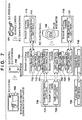
- Fig. 7 is a schematic view showing the data flow of the sensing information collection system according to this embodiment.
- the smartphone 102 serving as a mobile communication apparatus is connected to the wearable camera 101 serving as a sensing device via a Bluetooth communication path.
- the smartphone 102 provides a camera remote control service (Camera Remote Services 711 and 712).
- the smartphone 102 is connected to the pulse rate meter 104 serving as a sensing device via a Bluetooth communication path, and provides a health care information logging service (to be referred to as a health care service hereinafter) (Health Care Services 721 and 722).
- the in-vehicle information communication apparatus 103 is assumed to need a health care service to collect vital information from the pulse rate meter 104 worn by the user.
- the in-vehicle information communication apparatus 103 is assumed to need a camera remote control service to protect overwrite of image capturing information of the wearable camera of the user at the time of the occurrence of an emergency situation.
- the smartphone 102 is assumed to operate as a central device (Bluetooth Low Energy Central 700) on the Bluetooth communication path.
- the wearable camera 101 and the pulse rate meter 104 are assumed to operate as peripheral devices (Bluetooth Low Energy Peripherals 710 and 720).
- piconets using Bluetooth communication media are formed between the smartphone 102 and the wearable camera 101 and between the smartphone 102 and the pulse rate meter 104.
- the smartphone 102 can receive service data 713 and 723 from the wearable camera 101 and the pulse rate meter 104, respectively, using the piconets.
- proxy servers GATT Server [Proxy]
- 701 and 702 that redisclose the service data 713 and 723 received from the wearable camera 101 and the pulse rate meter 104 operate.
- the smartphone 102 operates as a peripheral device on the Bluetooth communication path. Accordingly, a piconet can also be formed between the smartphone 102 and the in-vehicle information communication apparatus 103 operating as a central device (Bluetooth Low Energy Central 730). That is, a scatter network is formed at this time.
- the smartphone 102 can disclose service data collected from the wearable camera 101 and the pulse rate meter 104 to the new central device (in-vehicle information communication apparatus 103) by the proxy servers 701 and 702.
- the smartphone 102 forms the scatter network and causes the proxy servers 701 and 702 to operate. This makes it possible to provide (redisclose) service data by the camera remote control service and provide (redisclose) service data by the health care service.
- the smartphone 102 can operate as a slave communication apparatus (Bluetooth Slave 740).
- the smartphone 102 may provide, for example, a music information distribution service (Audio Service) to the in-vehicle information communication apparatus 103 operating as a master communication apparatus (Bluetooth Master 750).
- a music information distribution service (Audio Service)
- Bluetooth Master 750 a master communication apparatus
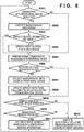
- Fig. 8 is a flowchart of processing of collecting sensing information and transmitting it to the in-vehicle information communication apparatus (IVI) 103 by the smartphone 102.
- the CPU of the control unit 305 of the smartphone 102 executes a program stored in the ROM 306, thereby executing the steps shown in Fig. 8 .
- the smartphone 102 determines whether BLE connection with the pulse rate meter 104 operating as a peripheral device (Bluetooth Low Energy Peripheral 720) via a Bluetooth communication path is detected (step S801).
- step S801 the smartphone 102 executes service search processing (Service Discovery) in accordance with SDP (Service Discovery Protocol) (step S802).
- service search processing the smartphone 102 recognizes that the newly connected pulse rate meter 104 is supporting and operating a Health Care Service.
- the smartphone 102 determines that the Health Care Service is a new service (provided service information is changed) for the smartphone 102 (NO in step S803).
- the smartphone 102 updates a proxy service item in the smartphone 102 (step S804). Then, the smartphone 102 activates the proxy server 702 of the Health Care Service such that the information of the Health Care Service that is a recognized service operating in the pulse rate meter 104 can be disclosed by proxy.
- the smartphone 102 starts normal communication processing with the pulse rate meter 104 (step S805). After completion of activation of the proxy server 702 (YES in step S806), the smartphone 102 acquires a measurement data value from the pulse rate meter 104 (step S807). In step S806, the measurement data value may be acquired from the pulse rate meter 104 at a timing determined as a data updating timing by the proxy server 702 (step S807).
- step S808 the proxy server 702 updates the service data 723 to be disclosed to the acquired data value (step S808).
- the service data 723 to be disclosed is thus equalized with the value disclosed by the pulse rate meter 104.
- the advertising packet 1100 to be transmitted by the smartphone 102 for a support service notification after the activation of the proxy server 702 in step S806 is set as follows as an example. That is, the "Control Flags" field 1105 in the AD Data field 1103 is set to "adaptable to scatter network", “Proxy Server operating", and "additional information element exists" (see Fig. 11 ).
- the smartphone 102 detects connection with the in-vehicle information communication apparatus 103 operating as a central device (Bluetooth Low Energy Central 730) (YES in step S809).
- the smartphone 102 determines the presence/absence of reception of a Service Search request (step S810).
- the smartphone 102 Upon receiving a Service Search request (YES in step S810), the smartphone 102 transmits a response to the Service Search request (step S811).
- the smartphone 102 independently of the reception of the Service Search request (NO in step S810), transmits the advertising packet at every predetermined reception timing (every advertising packet timing for a periodical support service notification) (step S812).
- the response and the advertising packet transmitted in steps S811 and S812 can include information (for example, UUID (Universally Unique Identifier)) to identify a service (here, the Health Care Service).
- the advertising packet transmitted in step S812 can also include information representing the presence/absence of a proxy service and the status of the service.
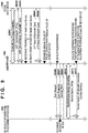
- Figs. 9 and 10 are views showing the operation sequence between the in-vehicle information communication apparatus 103, the smartphone 102, and the pulse rate meter 104.
- Fig. 9 shows a case in which the smartphone 102 detects the presence of the in-vehicle information communication apparatus 103
- Fig. 10 shows a case in which the in-vehicle information communication apparatus 103 detects the presence of the smartphone 102.
- the smartphone 102 upon detecting connection with the pulse rate meter 104, the smartphone 102 starts BLE connection with the pulse rate meter 104 (YES in step S801, and steps S901 and S1001). After that, the smartphone 102 transmits a service request signal (SDP_ServiceSearch REQ()) in accordance with SDP, thereby executing service search processing (steps S802, S902, and S1002). According to reception of the service request signal, the pulse rate meter 104 transmits a service response signal (SDP_ServiceSearch RES(Health Care)) representing that the pulse rate meter 104 supports a Health Care Service (steps S903 and S1003).
- the smartphone 102 Upon receiving the service response signal from the pulse rate meter 104, the smartphone 102 recognizes the presence of the Health Care Service (step S804), and activates the Proxy Server of the Health Care Service (YES in step S806). Next, the smartphone 102 transmits a measurement data request signal (ATT Read REQ(HealthCare)) to acquire a measurement data value from the pulse rate meter 104 (steps S904 and S1004). According to reception of the measurement data request signal, the pulse rate meter 104 transmits an assumed data response signal (ATT Read RES(HealthCare)) including the measurement data value (steps S905 and S1005).
- ATT Read REQ(HealthCare) to acquire a measurement data value from the pulse rate meter 104
- the pulse rate meter 104 transmits an assumed data response signal (ATT Read RES(HealthCare)) including the measurement data value (steps S905 and S1005).
- the smartphone 102 Upon receiving the measurement data value from the pulse rate meter 104 (step S807), the smartphone 102 equalizes service data to be disclosed with the measurement data value received from the pulse rate meter 104. More specifically, the smartphone 102 equalizes the Attribute value of the proxy server 702 with the Attribute value of the pulse rate meter 104.
- the smartphone 102 transmits an advertising signal including additional information (for example, representing that a proxy service (here, the Health Care Service) exists) (NO in step S809, and steps S812, S1006, and S1007).
- the in-vehicle information communication apparatus 103 receives the advertising signal, thereby detecting that the smartphone 102 exists in the neighborhood.
- the smartphone 102 does not transmit the advertising signal, and the in-vehicle information communication apparatus 103 transmits a scan request message (Scan Request) (steps S906 and S1008).
- Scan Request scan request message
- the scan request message is transmitted from the in-vehicle information communication apparatus 103 by Bluetooth communication when, for example, the user rides in (approaches) the vehicle in which the in-vehicle information communication apparatus 103 is mounted. Accordingly, the smartphone 102 detects that the in-vehicle information communication apparatus 103 exists in the neighborhood.
- the smartphone 102 Upon receiving the scan request message (steps S906 and S1008), the smartphone 102 returns a scan response (Scan Response) to the in-vehicle information communication apparatus 103 (steps S907 and S1009).
- the smartphone 102 transmits a connection request signal (Connect REQ), thereby shifting to a scatter network operation of Bluetooth communication with the in-vehicle information communication apparatus 103 (steps S909, S910, S1010, and S1011).
- the smartphone 102 After the shift to the scatter network, the smartphone 102 receives a Service Search request message from the in-vehicle information communication apparatus 103 via the Bluetooth communication path (YES in step S810, and steps S911 and S1012). The smartphone 102 then transmits a response message to the Service Search request message (steps S811, S912, and S1013).
- the message represents that the health care services 721 and 722 provided by the pulse rate meter 104 connected to the piconet to which the smartphone 102 itself is connected as a central device are being disclosed by proxy.
- a response message including information to identify the health care service is returned.
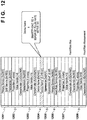
- Fig. 12 shows an example of the structure of Bluetooth GATT profile data representing that the proxy service of redisclosure of the health care service is supported.
- Fig. 12 shows an example in which the physical address (BD Address) of the pulse rate meter 104 is registered in a "Device Name" information area 1204, which is for storing a nickname of a device that provides the proxy service, together with the nickname of the smartphone 102.
- BD Address physical address
- Device Name information area 1204 which is for storing a nickname of a device that provides the proxy service, together with the nickname of the smartphone 102.
- the smartphone 102 may also return information for identifying a service (in this embodiment, Audio [music distribution]) provided/disclosed by the self-device using the response message (step S912 and S1013) (step S811).
- identifying a service in this embodiment, Audio [music distribution]
- the mobile communication apparatus is connected to the in-vehicle information communication apparatus or the like that is the central device on the upper piconet via the scatter network. This allows the in-vehicle information communication apparatus to enjoy the service provided by the sensing device of the lower piconet.
- the sensing information of the sensing device group managed by the mobile apparatus can be acquired and disclosed by proxy. More specifically, when the mobile apparatus is connected to the central device of the upper piconet via the scatter network, an acquired service provided by a peripheral device of the lower piconet can be disclosed to the central device of the upper piconet.
- the central device of the upper piconet is the in-vehicle information communication apparatus 103, and the peripheral devices of the lower piconet are the wearable camera 101 and the pulse rate meter 104. It is therefore possible to efficiently perform communication to use the service without needing a user operation of executing a pairing operation for each combination of devices that enjoy the service.
- Embodiment(s) of the present invention can also be realized by a computer of a system or apparatus that reads out and executes computer executable instructions (e.g., one or more programs) recorded on a storage medium (which may also be referred to more fully as a 'non-transitory computer-readable storage medium') to perform the functions of one or more of the above-described embodiment(s) and/or that includes one or more circuits (e.g., application specific integrated circuit (ASIC)) for performing the functions of one or more of the above-described embodiment(s), and by a method performed by the computer of the system or apparatus by, for example, reading out and executing the computer executable instructions from the storage medium to perform the functions of one or more of the above-described embodiment(s) and/or controlling the one or more circuits to perform the functions of one or more of the above-described embodiment(s).
- computer executable instructions e.g., one or more programs
- a storage medium which may also be referred to more fully as
- the computer may comprise one or more processors (e.g., central processing unit (CPU), micro processing unit (MPU)) and may include a network of separate computers or separate processors to read out and execute the computer executable instructions.
- the computer executable instructions may be provided to the computer, for example, from a network or the storage medium.
- the storage medium may include, for example, one or more of a hard disk, a random-access memory (RAM), a read only memory (ROM), a storage of distributed computing systems, an optical disk (such as a compact disc (CD), digital versatile disc (DVD), or Blu-ray Disc (BD)TM), a flash memory device, a memory card, and the like.
- a communication apparatus (102) capable of functioning as a central device and being connected to a first piconet and capable of functioning as a peripheral device and being connected to a second piconet using a communication method complying with a Bluetooth standard, receives (S902, S905), from a first device functioning as the peripheral device on the first piconet, information for identifying a service supported by the first device and data associated with the service, and transmits (S912) the information for identifying the service to a second device functioning as the central device on the second piconet.
Landscapes
- Engineering & Computer Science (AREA)
- Computer Networks & Wireless Communication (AREA)
- Signal Processing (AREA)
- Databases & Information Systems (AREA)
- Computer Security & Cryptography (AREA)
- Business, Economics & Management (AREA)
- Marketing (AREA)
- Telephone Function (AREA)
- Telephonic Communication Services (AREA)
- Mobile Radio Communication Systems (AREA)
Abstract
Description
- The present invention relates to a communication apparatus, a method of controlling the communication apparatus, and a program.
- In recent years, a radio sensor network system has been put to practical use, in which a communication apparatus collects a result measured by a sensing device existing in the neighborhood via communication by a short-range radio communication method and uses it as additional information of a service to be provided. In a system that uses Bluetooth® as one of short-range radio communication methods, when devices enjoy a radio sensor network service, a pairing operation needs to be executed for each combination of devices that enjoy the service.
- In addition, the system using Bluetooth can use a "scatter network function" that allows a communication apparatus to hold a piconet (network) already formed with a sensing device and also newly participate in a piconet formed by an information processing apparatus in the neighborhood. For example, consider an example in which a user who carries a mobile communication apparatus (for example, a smartphone) that is forming a piconet with a sensing device such as a pulse rate meter rides in a vehicle in which an in-vehicle information processing apparatus that is providing a Bluetooth audio service is mounted. In this case, the mobile communication apparatus can execute reproduction of music data stored in the mobile communication apparatus in the in-vehicle information processing apparatus by using the scatter network function.
- On the other hand, according to the evolution of an emergency notification system or the like on the occurrence of an accident, the in-vehicle information processing apparatus is required to automatically collect vital information measured by the sensing device held by the user. Although the standards of Bluetooth associated with the scatter network include a standard for the topology of communication connection, there is no standard for bridge/routing and the like of data. Hence, the in-vehicle information processing apparatus cannot acquire measurement information of the sensing device only by forming the scatter network by the mobile communication apparatus.
- To solve this problem, Japanese Patent Laid-Open No.
2013-59075 2006-515492 2013-537754 - In the above-described conventional technique, the in-vehicle information communication apparatus cannot acquire sensing information via the mobile communication apparatus only by forming the scatter network with the mobile communication apparatus that is operating as a master communication apparatus of a piconet for controlling a sensing device group. In addition, when temporarily using the service, a pairing operation between the in-vehicle information communication apparatus and each sensing device is necessary, and this operation is a burden on the user.
- The present invention provides a technique of efficiently performing communication to use a service in consideration of the above-described problem.
- The present invention in its first aspect provides a communication apparatus as specified in
Claims 1 to 11. - The present invention in its second aspect provides a method of controlling a communication apparatus as specified in Claim 12.
- The present invention in its third aspect provides a program as specified in Claim 13.
- Further features of the present invention will become apparent from the following description of exemplary embodiments (with reference to the attached drawings).
-
-
Fig. 1 is a schematic view of a sensing information collection system according to an embodiment; -
Fig. 2 is a block diagram showing an example of the hardware arrangement of a wearable camera; -
Fig. 3 is a block diagram showing an example of the hardware arrangement of asmartphone 102; -
Fig. 4 is a block diagram showing an example of the hardware arrangement of an in-vehicle information communication apparatus (IVI) 103; -
Fig. 5 is a block diagram showing an example of the hardware arrangement of apulse rate meter 104; -
Fig. 6 is a schematic view of a conventional sensing information collection system; -
Fig. 7 is a schematic view showing the data flow of the sensing information collection system according to the embodiment; -
Fig. 8 is a flowchart of processing of thesmartphone 102; -
Fig. 9 is a schematic view (1) showing the operation procedure of the sensing information collection system according to the embodiment; -
Fig. 10 is a schematic view (2) showing the operation procedure of the sensing information collection system according to the embodiment; -
Fig. 11 is a view showing an example of the data structure of an advertising packet; and -
Fig. 12 is a view showing an example of the data structure of Bluetooth GATT profile data. - The present invention will now be described in detail with reference to the accompanying drawings based on an example of the embodiment. Note that an arrangement shown in the following embodiment is merely an example, and the present invention is not limited to the illustrated arrangement.
-
Fig. 1 is a schematic view of a system (to be referred to as a sensing information collection system hereinafter) according to this embodiment, in which a result measured by a sensing device is collected via communication by a short-range radio communication method. This system is formed by awearable camera 101 and apulse rate meter 104 which serve as sensing devices, and asmartphone 102 and an in-vehicle information communication apparatus (IVI (In-Vehicle Infotainment)) 103 which serve as mobile communication apparatuses. Thewearable camera 101 and thepulse rate meter 104 are worn or held by, for example, the driver of a vehicle in which the in-vehicleinformation communication apparatus 103 is mounted. Each of thewearable camera 101, thesmartphone 102, the in-vehicleinformation communication apparatus 103, and thepulse rate meter 104 includes a radio communication interface based on the Bluetooth standard that is an example of short-range radio communication standards. Note that the devices are examples and are not limited to the devices shown inFig. 1 as long as each device is a device including a radio communication interface based on the Bluetooth standard. - In the description of this embodiment, the
smartphone 102 serving as a central device of BLE (Bluetooth Low Energy) connection forms a piconet with a sensing device (thewearable camera 101 and/or the pulse rate meter 104). The BLE connection is done via a Bluetooth communication path. The piconet will be referred to as a lower piconet. Here, thewearable camera 101 and thepulse rate meter 104 function as peripheral devices of BLE connection. In this state, thesmartphone 102 participates as a peripheral device in a piconet formed by the in-vehicleinformation communication apparatus 103 that is a central device of new BLE connection, thereby forming a scatter network. The piconet formed by the in-vehicleinformation communication apparatus 103 will be referred to as an upper piconet.Fig. 6 is a schematic view of a conventional sensing information collection system. Conventionally, as shown inFig. 6 , thesmartphone 102 can collect a measurement data value from a sensing device in the lower piconet. However, to allow the in-vehicleinformation communication apparatus 103 to collect the measurement data value from the sensing device, a pairing operation between the sensing device and the in-vehicleinformation communication apparatus 103 needs to be performed by the user. On the other hand, in this embodiment, thesmartphone 102 can transmit the measurement data value collected from the sensing device to the in-vehicleinformation communication apparatus 103 by proxy for the sensing device by performing processing to be described later. - The hardware arrangements of the
wearable camera 101, thesmartphone 102, the in-vehicleinformation communication apparatus 103, and thepulse rate meter 104 will be described next with reference toFigs. 2 to 5 . Thewearable camera 101 will be described first.Fig. 2 is a block diagram for explaining the hardware arrangement of thewearable camera 101. Thewearable camera 101 includes adisplay unit 201, anoperation unit 202, animage storage unit 203, apower supply unit 204, animage capturing unit 205, acontrol unit 206, aROM 207, aRAM 208, a wirelessLAN communication unit 209, and aBluetooth communication unit 210. Note that ROM stands for Read Only Memory, and RAM stands for Random Access Memory. - The
display unit 201 is formed by, for example, an LCD (Liquid Crystal Display) or the like, has a function of outputting information that can visually be recognized, and performs display such as display of a UI (User Interface), an alarm, and an image. Theoperation unit 202 has a function of performing various kinds of inputs and the like and operating the device. Theimage storage unit 203 is formed by, for example, a nonvolatile memory medium such as an SD card and stores image data. Thepower supply unit 204 holds a power supply (a battery or the like) used to operate the entire device and supplies power to each hardware. - The
image capturing unit 205 is formed by, for example, an image capturing engine mainly including a lens and an image sensor, and generates image data by encoding a captured image. Thecontrol unit 206 is formed by, for example, one or a plurality of CPUs (Central Processing Units), and controls the operation of the entirewearable camera 101. TheROM 207 stores control instructions, that is, programs. Various kinds of operations of thewearable camera 101 to be described later are implemented when thecontrol unit 206 executes a control program stored in theROM 207. TheRAM 208 is used as a work memory when executing a program or to temporarily save data. The wirelessLAN communication unit 209 performs communication (Wi-Fi® or the like) complying with the IEEE802.11 series, and is used for high-speed transfer of payload data such as image data. TheBluetooth communication unit 210 performs Bluetooth communication that is power-saving radio communication. - The
smartphone 102 will be described next.Fig. 3 is a block diagram for explaining the hardware arrangement of thesmartphone 102. Thesmartphone 102 includes adisplay unit 301, anoperation unit 302, animage storage unit 303, apower supply unit 304, acontrol unit 305, aROM 306, aRAM 307, a wirelessLAN communication unit 308, aBluetooth communication unit 309, and apublic communication unit 310. - The
display unit 301 is formed by, for example, an LCD or an LED (Light Emitting Diode), has a function of outputting information that can visually be recognized, and performs display of a UI, an alarm, and the like. Theoperation unit 302 has a function of performing various kinds of inputs and the like and operating the device. Theimage storage unit 303 stores image data. Thepower supply unit 304 holds a power supply (a battery or the like) used to operate the entire device and supplies power to each hardware. Thecontrol unit 305 is formed by one or a plurality of CPUs, and controls the operation of theentire smartphone 102. TheROM 306 stores control instructions, that is, programs. Various kinds of operations of thesmartphone 102 to be described later are implemented when thecontrol unit 305 executes a control program stored in theROM 306. TheRAM 307 is used as a work memory when executing a program or to temporarily save data. - The wireless
LAN communication unit 308 performs communication (Wi-Fi or the like) complying with the IEEE802.11 series. TheBluetooth communication unit 309 performs Bluetooth communication that is power-saving radio communication. In this embodiment, theBluetooth communication unit 309 communicates with the sensing devices (thewearable camera 101 and the pulse rate meter 104) in the neighborhood and the in-vehicleinformation communication apparatus 103. Thepublic communication unit 310 performs public radio communication such as 3GPP (3rd Generation Partnership Project) and LTE (Long Term Evolution). - The in-vehicle information communication apparatus (IVI) 103 will be described next.
Fig. 4 is a block diagram for explaining the hardware arrangement of the in-vehicle information communication apparatus. The in-vehicle information communication apparatus (IVI) 103 includes adisplay unit 401, anoperation unit 402, a mapinformation storage unit 403, apower supply unit 404, acontrol unit 405, aROM 406, aRAM 407, a wirelessLAN communication unit 408, aBluetooth communication unit 409, and apublic communication unit 410. - The
display unit 401 is formed by, for example, an LCD or an LED, has a function of outputting information that can visually be recognized, and performs display of a UI, an alarm, and the like. Theoperation unit 402 has a function of performing various kinds of inputs and the like and operating the device. The mapinformation storage unit 403 is formed by, for example, a nonvolatile memory medium such as an SD card and stores map information and the like. Thepower supply unit 404 converts the power supply voltage of an onboard battery into a power supply voltage used to operate the entire device and supplies power to each hardware. Thecontrol unit 405 is formed by one or a plurality of CPUs, and controls the operation of the entire in-vehicle information communication apparatus (IVI) 103. TheROM 406 stores control instructions, that is, programs. Various kinds of operations of the in-vehicle information communication apparatus (IVI) 103 to be described later are implemented when thecontrol unit 405 executes a control program stored in theROM 406. TheRAM 407 is used as a work memory when executing a program or to temporarily save data. - The wireless
LAN communication unit 408 performs communication (Wi-Fi or the like) complying with the IEEE802.11 series. TheBluetooth communication unit 409 performs Bluetooth communication that is power-saving radio communication. In this embodiment, theBluetooth communication unit 409 communicates with thesmartphone 102 in the neighborhood. Thepublic communication unit 410 performs public radio communication such as 3GPP and LTE. - The
pulse rate meter 104 will be described next.Fig. 5 is a block diagram for explaining the hardware arrangement of the wearablepulse rate meter 104. Thepulse rate meter 104 includes adisplay unit 501, anoperation unit 502, a measurementdata storage unit 503, apower supply unit 504, a bloodflow sensor unit 505, acontrol unit 506, aROM 507, aRAM 508, apulse sensor unit 509, and aBluetooth communication unit 510. - The
display unit 501 is formed by, for example, an LCD or the like, has a function of outputting information that can visually be recognized, and performs display such as display of a UI, an alarm, and an image. Theoperation unit 502 has a function of performing various kinds of inputs and the like and operating the device. The measurementdata storage unit 503 is formed by, for example, a nonvolatile memory medium such as an internal EEPROM (Electrically Erasable Programmable ROM) and stores a measurement data history and the like. Thepower supply unit 504 holds a power supply (a battery or the like) used to operate the entire device and supplies power to each hardware. - The blood
flow sensor unit 505 is formed by a sensor using, for example, a photoelectric element, and measures the blood flow in a blood vessel near the wearing portion. Thecontrol unit 506 is formed by one or a plurality of CPUs, and controls the operation of the entirepulse rate meter 104. TheROM 507 stores control instructions, that is, programs. Various kinds of operations of thepulse rate meter 104 to be described later are implemented when thecontrol unit 506 executes a control program stored in theROM 507. TheRAM 508 is used as a work memory when executing a program or to temporarily save data. Thepulse sensor unit 509 is formed by a sensor using a piezoelectric element, and measures the pulsation of a blood vessel near the wearing portion. TheBluetooth communication unit 510 performs Bluetooth communication that is power-saving radio communication. - An advertising packet that the
smartphone 102 transmits to notify its capability will be described next.Fig. 11 shows an example of the data structure of anadvertising packet 1100 transmitted by thesmartphone 102. Theadvertising packet 1100 is formed by aLength field 1101, an AD (Advertising Data)Type field 1102, and anAD Data field 1103. TheLength field 1101 is a field configured to notify the effective data length of the packet. The AD Type field is a field configured to designate the type of information notified using theadvertising packet 1100. The AD Data field is a field configured to store notification target data. - In this embodiment, assume that the
advertising packet 1100 is used to notify the in-vehicleinformation communication apparatus 103 of a service supported by thesmartphone 102. Hence, as an example, a value representing "GAP (Generic Access Profile) Access Profile" s set in theAD Type field 1102. Additionally, in an "Organization ID"field 1104 in theAD Data field 1103, a value representing "Automotive Organization" that defines subsequent information elements (1105, 1106, and 1107) in the field is stored. - Processing performed when a driver (to be referred to as a user hereinafter) who holds the
smartphone 102 and wears thewearable camera 101, and thepulse rate meter 104 rides in a vehicle in which the in-vehicleinformation communication apparatus 103 is mounted will be described next with reference toFigs. 7 to 12 . -
Fig. 7 is a schematic view showing the data flow of the sensing information collection system according to this embodiment. Thesmartphone 102 serving as a mobile communication apparatus is connected to thewearable camera 101 serving as a sensing device via a Bluetooth communication path. Thesmartphone 102 provides a camera remote control service (Camera Remote Services 711 and 712). In addition, thesmartphone 102 is connected to thepulse rate meter 104 serving as a sensing device via a Bluetooth communication path, and provides a health care information logging service (to be referred to as a health care service hereinafter) (Health Care Services 721 and 722). Here, the in-vehicleinformation communication apparatus 103 is assumed to need a health care service to collect vital information from thepulse rate meter 104 worn by the user. At the same time, the in-vehicleinformation communication apparatus 103 is assumed to need a camera remote control service to protect overwrite of image capturing information of the wearable camera of the user at the time of the occurrence of an emergency situation. - Here, the
smartphone 102 is assumed to operate as a central device (Bluetooth Low Energy Central 700) on the Bluetooth communication path. In addition, thewearable camera 101 and thepulse rate meter 104 are assumed to operate as peripheral devices (BluetoothLow Energy Peripherals 710 and 720). Hence, piconets using Bluetooth communication media are formed between thesmartphone 102 and thewearable camera 101 and between thesmartphone 102 and thepulse rate meter 104. Thesmartphone 102 can receiveservice data wearable camera 101 and thepulse rate meter 104, respectively, using the piconets. Additionally, in thesmartphone 102, proxy servers (GATT Server [Proxy]) 701 and 702 that redisclose theservice data wearable camera 101 and thepulse rate meter 104 operate. - In addition, the
smartphone 102 operates as a peripheral device on the Bluetooth communication path. Accordingly, a piconet can also be formed between thesmartphone 102 and the in-vehicleinformation communication apparatus 103 operating as a central device (Bluetooth Low Energy Central 730). That is, a scatter network is formed at this time. When the scatter network is formed, thesmartphone 102 can disclose service data collected from thewearable camera 101 and thepulse rate meter 104 to the new central device (in-vehicle information communication apparatus 103) by theproxy servers - In this way, in this embodiment, the
smartphone 102 forms the scatter network and causes theproxy servers - Note that on the Bluetooth communication path, the
smartphone 102 can operate as a slave communication apparatus (Bluetooth Slave 740). Hence, thesmartphone 102 may provide, for example, a music information distribution service (Audio Service) to the in-vehicleinformation communication apparatus 103 operating as a master communication apparatus (Bluetooth Master 750). - The operation of the
smartphone 102 will be described next with reference toFigs. 7 and8. Fig. 8 is a flowchart of processing of collecting sensing information and transmitting it to the in-vehicle information communication apparatus (IVI) 103 by thesmartphone 102. The CPU of thecontrol unit 305 of thesmartphone 102 executes a program stored in theROM 306, thereby executing the steps shown inFig. 8 . First, thesmartphone 102 determines whether BLE connection with thepulse rate meter 104 operating as a peripheral device (Bluetooth Low Energy Peripheral 720) via a Bluetooth communication path is detected (step S801). If BLE connection is detected (YES in step S801), thesmartphone 102 executes service search processing (Service Discovery) in accordance with SDP (Service Discovery Protocol) (step S802). By the service search processing, thesmartphone 102 recognizes that the newly connectedpulse rate meter 104 is supporting and operating a Health Care Service. In addition, thesmartphone 102 determines that the Health Care Service is a new service (provided service information is changed) for the smartphone 102 (NO in step S803). - Next, the
smartphone 102 updates a proxy service item in the smartphone 102 (step S804). Then, thesmartphone 102 activates theproxy server 702 of the Health Care Service such that the information of the Health Care Service that is a recognized service operating in thepulse rate meter 104 can be disclosed by proxy. Next, thesmartphone 102 starts normal communication processing with the pulse rate meter 104 (step S805). After completion of activation of the proxy server 702 (YES in step S806), thesmartphone 102 acquires a measurement data value from the pulse rate meter 104 (step S807). In step S806, the measurement data value may be acquired from thepulse rate meter 104 at a timing determined as a data updating timing by the proxy server 702 (step S807). In step S808, theproxy server 702 updates theservice data 723 to be disclosed to the acquired data value (step S808). Theservice data 723 to be disclosed is thus equalized with the value disclosed by thepulse rate meter 104. Note that theadvertising packet 1100 to be transmitted by thesmartphone 102 for a support service notification after the activation of theproxy server 702 in step S806 is set as follows as an example. That is, the "Control Flags"field 1105 in theAD Data field 1103 is set to "adaptable to scatter network", "Proxy Server operating", and "additional information element exists" (seeFig. 11 ). - Next, the
smartphone 102 detects connection with the in-vehicleinformation communication apparatus 103 operating as a central device (Bluetooth Low Energy Central 730) (YES in step S809). Next, thesmartphone 102 determines the presence/absence of reception of a Service Search request (step S810). Upon receiving a Service Search request (YES in step S810), thesmartphone 102 transmits a response to the Service Search request (step S811). In addition, independently of the reception of the Service Search request (NO in step S810), thesmartphone 102 transmits the advertising packet at every predetermined reception timing (every advertising packet timing for a periodical support service notification) (step S812). The response and the advertising packet transmitted in steps S811 and S812 can include information (for example, UUID (Universally Unique Identifier)) to identify a service (here, the Health Care Service). In addition, the advertising packet transmitted in step S812 can also include information representing the presence/absence of a proxy service and the status of the service. - The operation of each device in the sensing information collection system according to this embodiment will be described next with reference to
Figs. 9 and10 in association withFig. 8 .Figs. 9 and10 are views showing the operation sequence between the in-vehicleinformation communication apparatus 103, thesmartphone 102, and thepulse rate meter 104.Fig. 9 shows a case in which thesmartphone 102 detects the presence of the in-vehicleinformation communication apparatus 103, andFig. 10 shows a case in which the in-vehicleinformation communication apparatus 103 detects the presence of thesmartphone 102. - First, upon detecting connection with the
pulse rate meter 104, thesmartphone 102 starts BLE connection with the pulse rate meter 104 (YES in step S801, and steps S901 and S1001). After that, thesmartphone 102 transmits a service request signal (SDP_ServiceSearch REQ()) in accordance with SDP, thereby executing service search processing (steps S802, S902, and S1002). According to reception of the service request signal, thepulse rate meter 104 transmits a service response signal (SDP_ServiceSearch RES(Health Care)) representing that thepulse rate meter 104 supports a Health Care Service (steps S903 and S1003). Upon receiving the service response signal from thepulse rate meter 104, thesmartphone 102 recognizes the presence of the Health Care Service (step S804), and activates the Proxy Server of the Health Care Service (YES in step S806). Next, thesmartphone 102 transmits a measurement data request signal (ATT Read REQ(HealthCare)) to acquire a measurement data value from the pulse rate meter 104 (steps S904 and S1004). According to reception of the measurement data request signal, thepulse rate meter 104 transmits an assumed data response signal (ATT Read RES(HealthCare)) including the measurement data value (steps S905 and S1005). Upon receiving the measurement data value from the pulse rate meter 104 (step S807), thesmartphone 102 equalizes service data to be disclosed with the measurement data value received from thepulse rate meter 104. More specifically, thesmartphone 102 equalizes the Attribute value of theproxy server 702 with the Attribute value of thepulse rate meter 104. - After that, in the example shown in
Fig. 10 , thesmartphone 102 transmits an advertising signal including additional information (for example, representing that a proxy service (here, the Health Care Service) exists) (NO in step S809, and steps S812, S1006, and S1007). The in-vehicleinformation communication apparatus 103 receives the advertising signal, thereby detecting that thesmartphone 102 exists in the neighborhood. On the other hand, inFig. 9 , thesmartphone 102 does not transmit the advertising signal, and the in-vehicleinformation communication apparatus 103 transmits a scan request message (Scan Request) (steps S906 and S1008). The scan request message is transmitted from the in-vehicleinformation communication apparatus 103 by Bluetooth communication when, for example, the user rides in (approaches) the vehicle in which the in-vehicleinformation communication apparatus 103 is mounted. Accordingly, thesmartphone 102 detects that the in-vehicleinformation communication apparatus 103 exists in the neighborhood. - Upon receiving the scan request message (steps S906 and S1008), the
smartphone 102 returns a scan response (Scan Response) to the in-vehicle information communication apparatus 103 (steps S907 and S1009). Thesmartphone 102 transmits a connection request signal (Connect REQ), thereby shifting to a scatter network operation of Bluetooth communication with the in-vehicle information communication apparatus 103 (steps S909, S910, S1010, and S1011). - After the shift to the scatter network, the
smartphone 102 receives a Service Search request message from the in-vehicleinformation communication apparatus 103 via the Bluetooth communication path (YES in step S810, and steps S911 and S1012). Thesmartphone 102 then transmits a response message to the Service Search request message (steps S811, S912, and S1013). The message represents that thehealth care services pulse rate meter 104 connected to the piconet to which thesmartphone 102 itself is connected as a central device are being disclosed by proxy. Here, for example, a response message including information to identify the health care service is returned. -
Fig. 12 shows an example of the structure of Bluetooth GATT profile data representing that the proxy service of redisclosure of the health care service is supported.Fig. 12 shows an example in which the physical address (BD Address) of thepulse rate meter 104 is registered in a "Device Name"information area 1204, which is for storing a nickname of a device that provides the proxy service, together with the nickname of thesmartphone 102. - Note that the
smartphone 102 may also return information for identifying a service (in this embodiment, Audio [music distribution]) provided/disclosed by the self-device using the response message (step S912 and S1013) (step S811). - As described above, according to this embodiment, the mobile communication apparatus is connected to the in-vehicle information communication apparatus or the like that is the central device on the upper piconet via the scatter network. This allows the in-vehicle information communication apparatus to enjoy the service provided by the sensing device of the lower piconet.
- In the above-described embodiment, an example in which provided service information is transmitted/received using an SDS (Service Discovery Service) executed after setting of the Bluetooth communication path has been described. Here, if the data length of the Profile data structure that is needed to be transmitted/received is equal to or less than the size (1107) of the data information area of an SDP1 packet, the SDP executed after setting of the Bluetooth communication path may be used. Even when the provided service information is transmitted/received using the SDP, the same effect as described above can be obtained.
- According to this embodiment, when the mobile apparatus (smartphone 102) operating as a central device on the piconet forms the scatter network, the sensing information of the sensing device group managed by the mobile apparatus can be acquired and disclosed by proxy. More specifically, when the mobile apparatus is connected to the central device of the upper piconet via the scatter network, an acquired service provided by a peripheral device of the lower piconet can be disclosed to the central device of the upper piconet. In this embodiment, the central device of the upper piconet is the in-vehicle
information communication apparatus 103, and the peripheral devices of the lower piconet are thewearable camera 101 and thepulse rate meter 104. It is therefore possible to efficiently perform communication to use the service without needing a user operation of executing a pairing operation for each combination of devices that enjoy the service. - Note that in the above-described embodiment, formation of a plurality of piconets using a communication method complying with the Bluetooth standard has been described as an example. This embodiment can also be applied to formation of a plurality of networks including a master station (central device) and a slave station (peripheral device) using another short-range radio communication method in place of Bluetooth.
- Embodiment(s) of the present invention can also be realized by a computer of a system or apparatus that reads out and executes computer executable instructions (e.g., one or more programs) recorded on a storage medium (which may also be referred to more fully as a 'non-transitory computer-readable storage medium') to perform the functions of one or more of the above-described embodiment(s) and/or that includes one or more circuits (e.g., application specific integrated circuit (ASIC)) for performing the functions of one or more of the above-described embodiment(s), and by a method performed by the computer of the system or apparatus by, for example, reading out and executing the computer executable instructions from the storage medium to perform the functions of one or more of the above-described embodiment(s) and/or controlling the one or more circuits to perform the functions of one or more of the above-described embodiment(s). The computer may comprise one or more processors (e.g., central processing unit (CPU), micro processing unit (MPU)) and may include a network of separate computers or separate processors to read out and execute the computer executable instructions. The computer executable instructions may be provided to the computer, for example, from a network or the storage medium. The storage medium may include, for example, one or more of a hard disk, a random-access memory (RAM), a read only memory (ROM), a storage of distributed computing systems, an optical disk (such as a compact disc (CD), digital versatile disc (DVD), or Blu-ray Disc (BD)™), a flash memory device, a memory card, and the like.
- While the present invention has been described with reference to exemplary embodiments, it is to be understood that the invention is not limited to the disclosed exemplary embodiments. The scope of the following claims is to be accorded the broadest interpretation so as to encompass all such modifications and equivalent structures and functions.
- A communication apparatus (102) capable of functioning as a central device and being connected to a first piconet and capable of functioning as a peripheral device and being connected to a second piconet using a communication method complying with a Bluetooth standard, receives (S902, S905), from a first device functioning as the peripheral device on the first piconet, information for identifying a service supported by the first device and data associated with the service, and transmits (S912) the information for identifying the service to a second device functioning as the central device on the second piconet.
Claims (13)
- A communication apparatus (102) capable of functioning as a central device and being connected to a first piconet and capable of functioning as a peripheral device and being connected to a second piconet using a communication method complying with a Bluetooth standard, characterized by comprising:first communication means (309) for receiving, from a first device functioning as the peripheral device on the first piconet, information for identifying a service supported by the first device and data associated with the service; andsecond communication means (309) for transmitting the information for identifying the service to a second device functioning as the central device on the second piconet.
- The apparatus according to claim 1, characterized in that upon receiving a request to search for a service from the second device, the second communication means transmits the information for identifying the service.
- The apparatus according to claim 1, characterized in that the second communication means transmits the information for identifying the service at every predetermined timing.
- The apparatus according to any one of claims 1 to 3, characterized in that the second communication means transmits information for identifying a service supported by the communication apparatus to the second device together with the information for identifying the service.
- The apparatus according to claim 2, characterized in that the data associated with the service is included in a response received from the first device in accordance with the transmission of the request to search for the service to the first device by the first communication means.
- The apparatus according to any one of claims 1 to 5, characterized in that the first device is a device having a function of sensing a predetermined target, and the data associated with the service is measurement data sensed by the first device.
- The apparatus according to any one of claims 1 to 6, characterized by further comprising control means (305) for updating data to be transmitted to the second device to the data associated with the service,
wherein the second communication means transmits the updated data to the second device. - The apparatus according to any one of claims 1 to 7, characterized in that the information for identifying the service includes a UUID (Universally Unique Identifier).
- The apparatus according to claim 1, characterized in that the second communication means transmits the information for identifying the service and the data associated with the service.
- The apparatus according to claim 1, characterized in that the second communication means transmits an advertising signal including the information for identifying the service and/or a ServiceSearch RES signal.
- A communication apparatus (102) capable of functioning as a master station and being connected to a first network and capable of functioning as a slave station and being connected to a second network using a predetermined short-range radio communication method, characterized by comprising:first communication means (309) for receiving, from a first device functioning as the slave station on the first network, information for identifying a service supported by the first device and data associated with the service; andsecond communication means (309) for transmitting the information for identifying the service to a second device functioning as the master station on the second network.
- A method of controlling a communication apparatus (102) capable of functioning as a central device and being connected to a first piconet and capable of functioning as a peripheral device and being connected to a second piconet using a communication method complying with a Bluetooth standard, characterized by comprising:receiving (S903, S905), from a first device functioning as the peripheral device on the first piconet, information for identifying a service supported by the first device and data associated with the service; andtransmitting (S912) the information for identifying the service to a second device functioning as the central device on the second piconet.
- A program that, when executed on a communication apparatus, causes the communication apparatus to perform a method according to claim 12.
Applications Claiming Priority (1)
| Application Number | Priority Date | Filing Date | Title |
|---|---|---|---|
| JP2017125589A JP6966881B2 (en) | 2017-06-27 | 2017-06-27 | Communication equipment, control methods for communication equipment, and programs |
Publications (1)
| Publication Number | Publication Date |
|---|---|
| EP3422801A1 true EP3422801A1 (en) | 2019-01-02 |
Family
ID=62684590
Family Applications (1)
| Application Number | Title | Priority Date | Filing Date |
|---|---|---|---|
| EP18176450.7A Withdrawn EP3422801A1 (en) | 2017-06-27 | 2018-06-07 | Communication apparatus, method of controlling communication apparatus, and program |
Country Status (4)
| Country | Link |
|---|---|
| US (1) | US10728938B2 (en) |
| EP (1) | EP3422801A1 (en) |
| JP (1) | JP6966881B2 (en) |
| CN (1) | CN109151778A (en) |
Families Citing this family (6)
| Publication number | Priority date | Publication date | Assignee | Title |
|---|---|---|---|---|
| WO2020118450A1 (en) * | 2018-12-15 | 2020-06-18 | Genetec Inc. | Method and system for enrolling a camera into a video surveillance system |
| KR102792594B1 (en) * | 2020-07-31 | 2025-04-08 | 주식회사 모카시스템 | Reader and control method thereof |
| EP3989610B1 (en) * | 2020-10-20 | 2024-12-25 | Televic Healthcare NV | Device, system and method for clustering ble devices |
| CN112689275B (en) * | 2020-12-23 | 2024-04-16 | 阳光学院 | Novel non-uniform power forming method for BLE mesh network |
| US20230345554A1 (en) * | 2021-01-14 | 2023-10-26 | Ntt Docomo, Inc. | Wireless connection device |
| EP4580224A1 (en) * | 2023-12-27 | 2025-07-02 | INTEL Corporation | Methods and devices for in-vehicle intelligent transportation systems |
Citations (5)
| Publication number | Priority date | Publication date | Assignee | Title |
|---|---|---|---|---|
| US20050180343A1 (en) * | 2002-03-12 | 2005-08-18 | Van Valkenburg Sander | Method and device for wireless network formation |
| JP2006515492A (en) | 2003-07-11 | 2006-05-25 | モトローラ・インコーポレイテッド | Wireless communication network and method for enabling wireless presence-based service |
| JP2013059075A (en) | 2008-03-03 | 2013-03-28 | Qualcomm Inc | Promoting power savings in wireless client terminals |
| EP2582182A1 (en) * | 2011-10-14 | 2013-04-17 | IHP GmbH-Innovations for High Performance Microelectronics/Institut für innovative Mikroelektronik | Bluetooth scatternet tree formation for wireless sensor networks |
| JP2013537754A (en) | 2010-07-26 | 2013-10-03 | セブン ネットワークス インコーポレイテッド | Mobile application traffic optimization |
Family Cites Families (8)
| Publication number | Priority date | Publication date | Assignee | Title |
|---|---|---|---|---|
| JP2002297830A (en) * | 2001-03-30 | 2002-10-11 | Toshiba Corp | Data collection system and data collection method |
| US7222160B2 (en) * | 2001-07-20 | 2007-05-22 | Sharp Laboratories Of America, Inc. | Object search and retrieval service for an ad hoc data communication system |
| JP2004288025A (en) * | 2003-03-24 | 2004-10-14 | Fuji Xerox Co Ltd | Service processor, service processing system, original data storing method of service processing system, and service processing program |
| JP6287177B2 (en) * | 2013-12-25 | 2018-03-07 | カシオ計算機株式会社 | Wireless device, connection selection request method, connection selection method, program, wireless communication system, and wireless connection method |
| US9769594B2 (en) * | 2015-01-30 | 2017-09-19 | Cassia Networks Inc. | Methods, devices and systems for increasing wireless communication range |
| CN104980839B (en) * | 2015-07-08 | 2018-02-23 | 广东翼卡车联网服务有限公司 | A kind of vehicle intelligent bluetooth earphone and its implementation |
| CN105635460B (en) * | 2015-12-30 | 2019-09-24 | 北京搜狗科技发展有限公司 | A kind of control method, mobile terminal and wearable device for information output |
| CN106686541A (en) * | 2017-03-22 | 2017-05-17 | 北京小米移动软件有限公司 | Bluetooth relay method and device |
-
2017
- 2017-06-27 JP JP2017125589A patent/JP6966881B2/en active Active
-
2018
- 2018-06-07 EP EP18176450.7A patent/EP3422801A1/en not_active Withdrawn
- 2018-06-19 US US16/012,127 patent/US10728938B2/en active Active
- 2018-06-27 CN CN201810679919.6A patent/CN109151778A/en active Pending
Patent Citations (5)
| Publication number | Priority date | Publication date | Assignee | Title |
|---|---|---|---|---|
| US20050180343A1 (en) * | 2002-03-12 | 2005-08-18 | Van Valkenburg Sander | Method and device for wireless network formation |
| JP2006515492A (en) | 2003-07-11 | 2006-05-25 | モトローラ・インコーポレイテッド | Wireless communication network and method for enabling wireless presence-based service |
| JP2013059075A (en) | 2008-03-03 | 2013-03-28 | Qualcomm Inc | Promoting power savings in wireless client terminals |
| JP2013537754A (en) | 2010-07-26 | 2013-10-03 | セブン ネットワークス インコーポレイテッド | Mobile application traffic optimization |
| EP2582182A1 (en) * | 2011-10-14 | 2013-04-17 | IHP GmbH-Innovations for High Performance Microelectronics/Institut für innovative Mikroelektronik | Bluetooth scatternet tree formation for wireless sensor networks |
Non-Patent Citations (2)
| Title |
|---|
| GEORGE OIKONOMOU ET AL: "ADDER: Probabilistic, Application Layer Service Discovery for MANETs and Hybrid Wired-Wireless Networks", COMMUNICATION NETWORKS AND SERVICES RESEARCH CONFERENCE (CNSR), 2011 NINTH ANNUAL, IEEE, 2 May 2011 (2011-05-02), pages 33 - 40, XP031869889, ISBN: 978-1-4577-0040-8, DOI: 10.1109/CNSR.2011.14 * |
| NORDBOTTEN N A ET AL: "Methods for service discovery in Bluetooth scatternets", COMPUTER COMMUNICATI, ELSEVIER SCIENCE PUBLISHERS BV, AMSTERDAM, NL, vol. 27, no. 11, 1 July 2004 (2004-07-01), pages 1087 - 1096, XP004503638, ISSN: 0140-3664, DOI: 10.1016/J.COMCOM.2004.01.013 * |
Also Published As
| Publication number | Publication date |
|---|---|
| JP2019009695A (en) | 2019-01-17 |
| JP6966881B2 (en) | 2021-11-17 |
| US10728938B2 (en) | 2020-07-28 |
| US20180376527A1 (en) | 2018-12-27 |
| CN109151778A (en) | 2019-01-04 |
Similar Documents
| Publication | Publication Date | Title |
|---|---|---|
| EP3422801A1 (en) | Communication apparatus, method of controlling communication apparatus, and program | |
| CN110557849B (en) | A communication method and device | |
| US20260059263A1 (en) | Beacon Addressing | |
| US9913148B2 (en) | Data processing apparatus that discriminates a network formed by a normal access point from a network formed by a simple access point function | |
| CN114667747B (en) | Electronic device supporting proximity communication service and method for obtaining information of short-range communication device using the same | |
| US9998989B2 (en) | Wakeup method for devices in power saving mode | |
| US10591589B2 (en) | Apparatus and method for measuring wireless range | |
| KR102069265B1 (en) | Apparatus, methods and computer programs for establishing a communication connection between a vehicle's information system and a mobile device | |
| US9723426B2 (en) | Subscription-aware and updates-aware SIM process | |
| KR20170060735A (en) | Method for synchronizing proximity network and an electronic device thereof | |
| CN105723350A (en) | Method and apparatus for connecting communication of electronic devices | |
| KR20220018874A (en) | Method and apparatus for managing wireless connections of electronic device | |
| US10327125B2 (en) | Communication apparatus, control method for communication apparatus, and non-transitory computer-readable storage medium | |
| US9380615B2 (en) | Managing a group of wireless devices in close proximity | |
| JP5408230B2 (en) | Network system, node device group, sensor device group, and sensor data transmission / reception method | |
| CN104113582A (en) | Communication Apparatus And Control Method Thereof | |
| US20190245947A1 (en) | Communication device, communication method, program, and communication system | |
| US20160337837A1 (en) | Providing information to a service in a communication network | |
| US9986088B2 (en) | Automated MDN line transfer | |
| JP2017508425A (en) | System and method for detecting handshake | |
| JP2017092865A (en) | Communication device | |
| JP2019062249A (en) | Communication device, control method of communication device, and program | |
| JP5172759B2 (en) | Mutual discovery device | |
| TW201911893A (en) | Method, transmitting node and receiving node for feedback control of sidelink communication | |
| JP2014103506A (en) | Terminal device |
Legal Events
| Date | Code | Title | Description |
|---|---|---|---|
| PUAI | Public reference made under article 153(3) epc to a published international application that has entered the european phase |
Free format text: ORIGINAL CODE: 0009012 |
|
| STAA | Information on the status of an ep patent application or granted ep patent |
Free format text: STATUS: THE APPLICATION HAS BEEN PUBLISHED |
|
| AK | Designated contracting states |
Kind code of ref document: A1 Designated state(s): AL AT BE BG CH CY CZ DE DK EE ES FI FR GB GR HR HU IE IS IT LI LT LU LV MC MK MT NL NO PL PT RO RS SE SI SK SM TR |
|
| AX | Request for extension of the european patent |
Extension state: BA ME |
|
| STAA | Information on the status of an ep patent application or granted ep patent |
Free format text: STATUS: REQUEST FOR EXAMINATION WAS MADE |
|
| 17P | Request for examination filed |
Effective date: 20190702 |
|
| RBV | Designated contracting states (corrected) |
Designated state(s): AL AT BE BG CH CY CZ DE DK EE ES FI FR GB GR HR HU IE IS IT LI LT LU LV MC MK MT NL NO PL PT RO RS SE SI SK SM TR |
|
| STAA | Information on the status of an ep patent application or granted ep patent |
Free format text: STATUS: EXAMINATION IS IN PROGRESS |
|
| 17Q | First examination report despatched |
Effective date: 20201116 |
|
| STAA | Information on the status of an ep patent application or granted ep patent |
Free format text: STATUS: THE APPLICATION HAS BEEN WITHDRAWN |
|
| 18W | Application withdrawn |
Effective date: 20230207 |